

Page 1
D04
Multi-link Signal Relay
Page 2

2
Contents
Disclaimer
Product Introduction
Packing List
Product instructions
Radio Power On and Off
Status Indicator Instructions
Ground Unit and PC Communication
Wireless network selection and setup
.....................................................................................................................
....................................................................................................
...................................................................................................................
.....................................................................................................
..............................................................................................
......................................................................................
Ground Unit Indicator
Receiver Indicator
.................................................................................
.......................................................................................
WIFI Wireless Network Connection
BLE Wireless Network Connection
Datalink Link Communication Test
Radio Parameter Configuration
Ground Unit Battery Charging
Radio Alarm
Failsafe Setting
WiFI Module Parameter Setting
................................................................................................................
...........................................................................................................
.............................................................................
.................................................................................
...................................................................................
................................................................................
BLE Module Parameter Setting
........................................................................
......................................................................
............................................................
.............................................................
...................................................................
3
5
6
7
9
10
10
11
12
13
13
15
20
21
26
27
28
29
34
BLE and WIFI Modules are Restored to Factory Settings
Check the Radio System Firmware Version
Firmware Upgrade Steps
............................................................................................
Ground unit Firmware upgrade
Receiver firmware upgrade
.............................................................................................................................
FAQ
...........................
...............................................................
..................................................................
........................................................................
36
37
38
38
41
43
Page 3

3
Disclaimer
Thank you for purchasing the D04 Dual Link Radio (hereafter referred to as "D04").
Please use D04 according to local radio regulations. Please read this statement
carefully before using it. Once used, it is deemed to be an endorsement and
acceptance of the entire contents of this statement. Please strictly follow the
instructions to install and use the product. FOXTECH Co., Ltd. will not assume any
legal responsibility for any result or loss caused by improper use, installation,
assembly and modification of the user.
Product Note:
1. D04 is used as the ground end (hereinafter referred to as "ground end") in
conjunction with the sky end R20 (hereinafter referred to as "sky end" or "airborne
end").
2. Built-in 12V battery on the ground (18s battery for 3s), external power input
DC7.4 - 12V (lithium battery 2s - 3s), please supply power to the radio in strict
accordance with the specifications.
3. Be sure to install the antenna before powering up to avoid damage to the circuit.
4. Ensure that the antenna is obstructed during the use of the antenna, without
bending, and as far as possible away from the large metal structural parts, to avoid
communication obstruction due to the above reasons.
5. Do not disassemble or modify it without permission. If you encounter problems
that cannot be solved during installation or use, please contact Huazhiyi or your
agent.
6. Pay attention to keep the proper distance between the electronic devices during
installation to minimize electromagnetic interference between devices.
7. Make sure all connections are securely fastened and all parts are working
properly before use.
8. Please check the surrounding environment before use to ensure that there is no
interference from other 840MHZ-930MHZ equipment, otherwise the radio data
transmission may be seriously affected.
Page 4

4
9. For better service customers, we have been optimizing the product upgrade. The
matching software and firmware of the product will be updated and updated from
time to time. There may be incompatibility between different firmware versions on
the ground and onboard. So please pay attention to check the software firmware
version when using. Please also pay attention to our website to get the latest
software firmware and technical support.
10. The software, firmware, drivers, port conversion tools, etc. involved in this
manual will be updated from time to time on our website. Please visit our website
to download it yourself or contact customer service.
Page 5

5
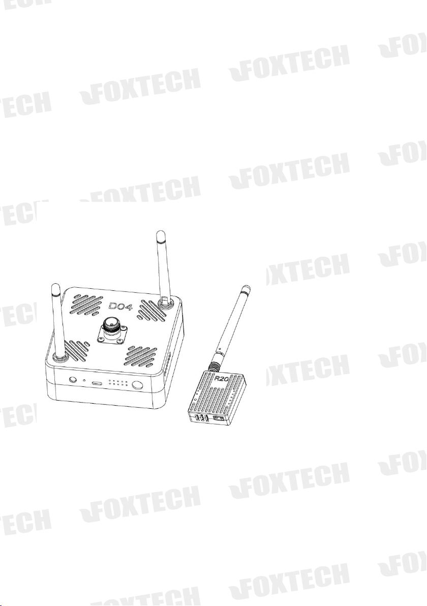
Product Introduction
The D04 is a multi-link signal relay system that can simultaneously transmit up to
two independent S-BUS data and one serial port data. By using D04 signal relay
The remote control signal can be enhanced and transmitted to the air unit together
with the TTL signal.So D04 Multi-link Signal Relay solves the problem of short
transmission distance of the remote controller and datalink. D04 features small size,
good integration and high sensitivity. The ground unit is integrated with wireless
network module (WIFI or BLE can be selected according to requirements), so users
can connect to RB20W ground unit by wireless network or USB data cable.
The wireless network can reach a stable coverage of 30~50M without interference.
D04 signal relay works in 840MHZ~915HZ frequency band and the maximum
communication distance is up to 30KM.
Page 6
6
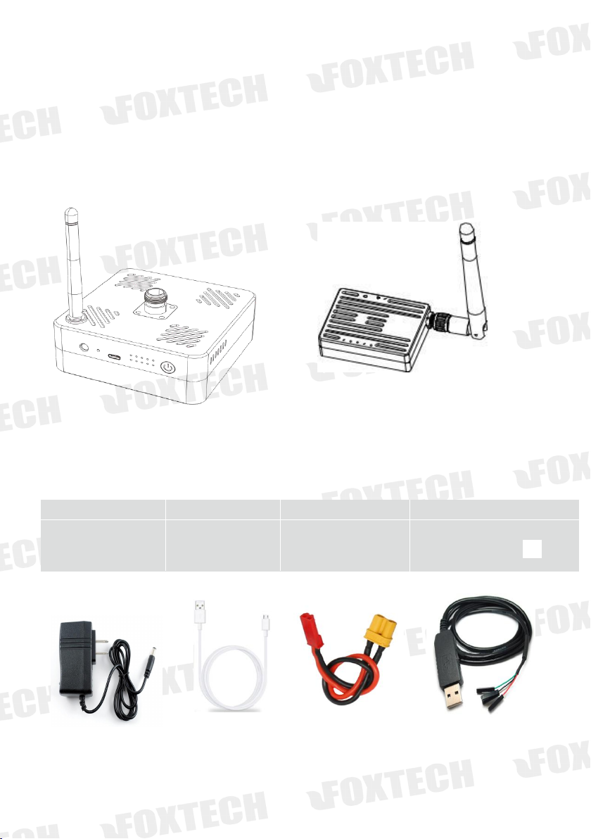
Packing List
Cahrger×1
USB cable×1
Power cable×1
Parameter setting
For ground unit
For parameter
setting
For air unit
(DC:7.4-12V)
For air unit
Ground Unit ×1
Air Unit x 1
Main Module
Accessories
Page 7
7
Product instructions
D04 can simultaneously transmit up to two independent S-BUS data and one serial
port data. There are two ways to access the serial port data on the ground. One is
to input directly through the USB data line, and the other is to transmit through the
WIFI or BLE wireless network. When D04 detects the USB data cable insertion, it
uses USB to transmit the serial port data preferentially. When it is detected that the
USB data cable is not inserted, D04 automatically switches to your preset wireless
module (WIFI or BLE) to transmit the serial port data. If your remote control or
receiver does not support S-BUS, you will need to purchase a separate PWM to
S-BUS module.
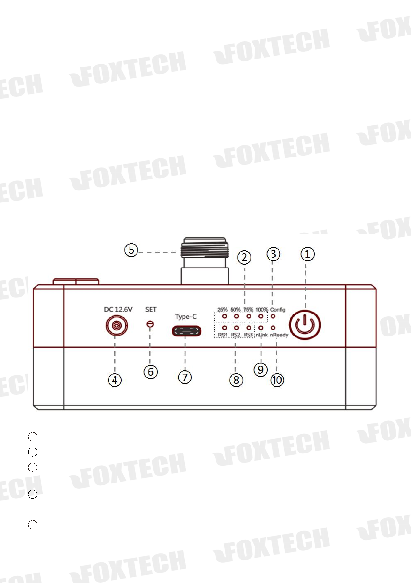
Ground Unit
1 Power indicator and button PWR
2 4 power indicator 25% ,50%, 75%, 100%
3 Config indicator
2 S-BUS signal input,or config type
4 Charge port
Support only DC 12.6V input
5 Antenna interface
Page 8
8
SMA
6
SET button
For parameter setting
7
USB port Type-C
For parameter setting or data transmission, not batter charge port
8
Data transmission module signal indicator
Indicator RS1 RS2 RS3 is the signal strength indicator. The number of lights indicates the strength of the
signal quality of the high-frequency data transmission module. It can also be used to indicate the type of
wireless network configuration in the configuration mode.
9
wireless network connection status indicator nLink
The indicator light indicates that the wireless network is connected or transmitting data, and the indicator is off
indicating that the wireless network is not connected or is not transmitting data.
10
Working status indicator of wireless network nReady
When the indicator is on, the wireless module is working properly and can connect and transfer data.
Ground unit connection
diagram
Page 9

9
Radio Power On and Off
1. After pressing the power button PWR, the power indicator lights up and the four
battery indicator lights start to flash simultaneously.
2. During the period when the battery indicator flashes (about 5S), release the
power button and press and hold the power button again. At this time, the four
battery indicators will light up in the way of the water lamp until the buzzer sounds
long. Indicates that the boot action is complete.
3. The shutdown operation is the same as the startup operation. The flow direction
indication is different from the startup only when the button is pressed for a long
time.
Page 10
10
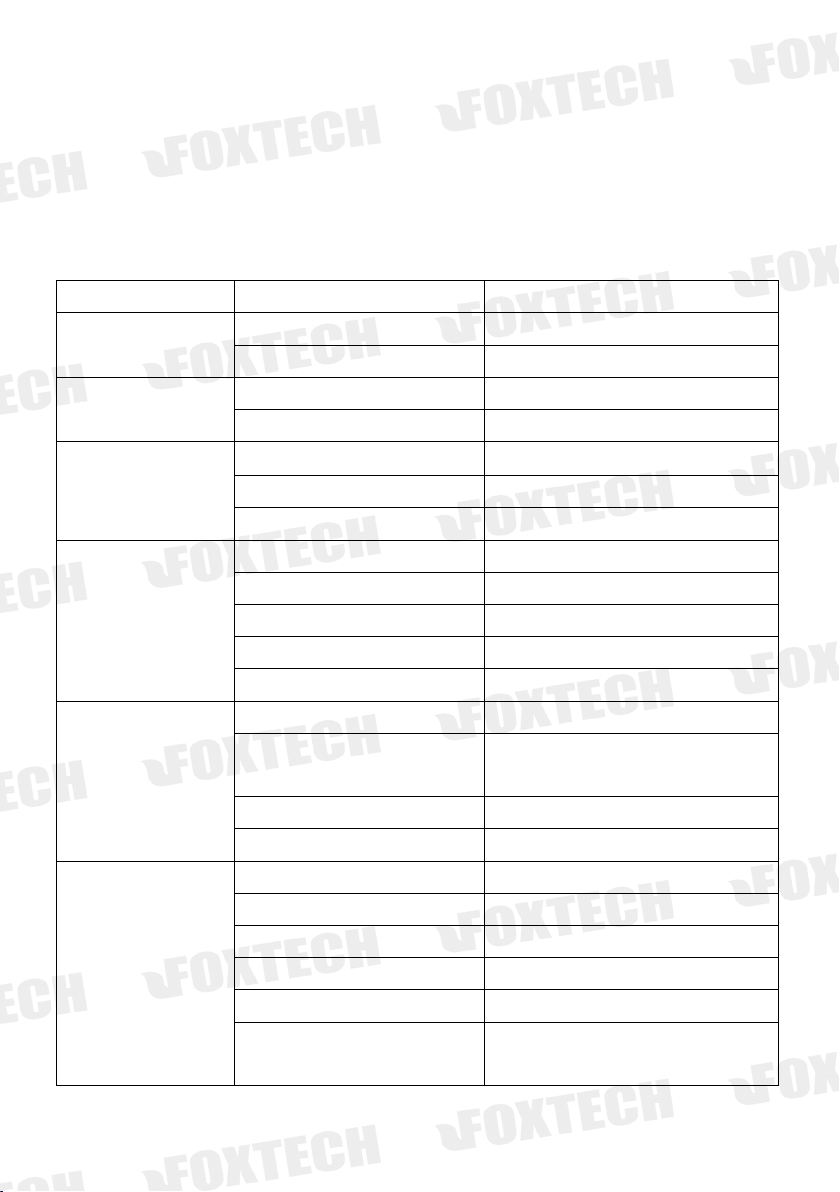
Status Indicator Instructions
Indicator
status
implication
RS1,RS2,RS3 Configuration
mode
RS1 flash,RS2 和 RS3 go out
current wireless mode is WIFI
RS 1and RS2 flash, RS3 go out
current wireless mode is BLE
RS1,RS2,RS3 status before
turned on
RS1 is on,RS2and RS3 go out
current wireless mode is WIFI
RS 1and RS2 are on, RS3 goes out
current wireless mode is BLE
RS1,RS2,RS3working status
RS1,RS2,RS3 are on
High frequency module signal is strong
RS 1and RS2 is on,RS3 go out
High frequency module signal is general
RS1 is on,RS2and RS3 goes out
High frequency module signal is weak
Config
Always being on
In high frequency module config. mode
Go out
SBUS1 and SBUS2 no signal input
One flash a time
SBUS1 has signal input
Two flashes a time
SBUS2 has signal input
Quich flashing
SBUS1 and SBUS2 has signal input
PWR power indicator
flash
Firmware upgrade status in configuration mode
flash, with short continuous sound of
buzzer
Low voltage alarm
Always being on
Radio is powered on,in normal working status
Go out
Radio is powered off
4 power capacity indicator
25% flash, other 3 go out
LOW BATTERY less than 25%
25% flash,other 3 go out
Power during 25%~50%
25% and 50% is on ,other 2go out
Power during 50%~75%
25%、50% and 75% on,100% goes out
during 75%~100%
25%、50%、75%和 100% all are on
Fully charged 100%
All 4 flash, with short continuous
sound of buzzer
High temperature protection status
Ground Unit Indicator
Page 11
11
nReady
on
The wireless module works normally and forms
a wireless network
off
The wireless module does not work properly
and does not form a wireless network
nLink
On
Wireless network data transmission is normal
off
Wireless network data transmission is abnormal
4 battery indicator lights from full-on state to full-off. After 5S, the
nReady indicator lights off first and then lights up.
The wireless module restored factory Settings
successfully
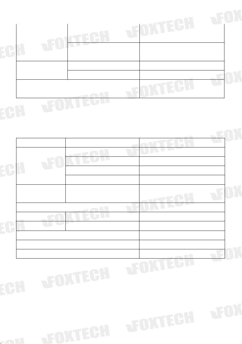
Receiver Indicator
indicator
status
implication
L1 灯
off
SBUS1 and SBUS2 no signal transmission
One flash a time
SBUS1 has signal transmission
One flash a time
SBUS2 has signal transmission
Quick flashing
SBUS1 and SBUS2 has signal transmission
L2 灯
Always being on
The receiver is in high frequency configuration
mode with no power output
L1、L2 always being on at the same time
The receiver is in firmware upgrade mode
RXD 灯
flash
Receiver has data reception
TXD 灯
flash
Receiver has data re-transmit
S1、S2、S3all on
Strong signal quality
S1 off,S2 and S3 on
Middle level of signal quality
S1 and S2 off,S3 flashes
weak signal quality
Page 12
12
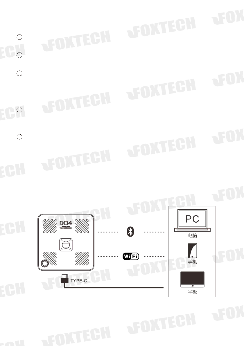
Ground Unit and PC Communication
The communication between the ground terminal and the host computer uses the
USB data cable by default. If the USB data cable is not connected, the radio station
will automatically switch to the preset wireless module (WIFI or BLE) to transmit
the serial port data.
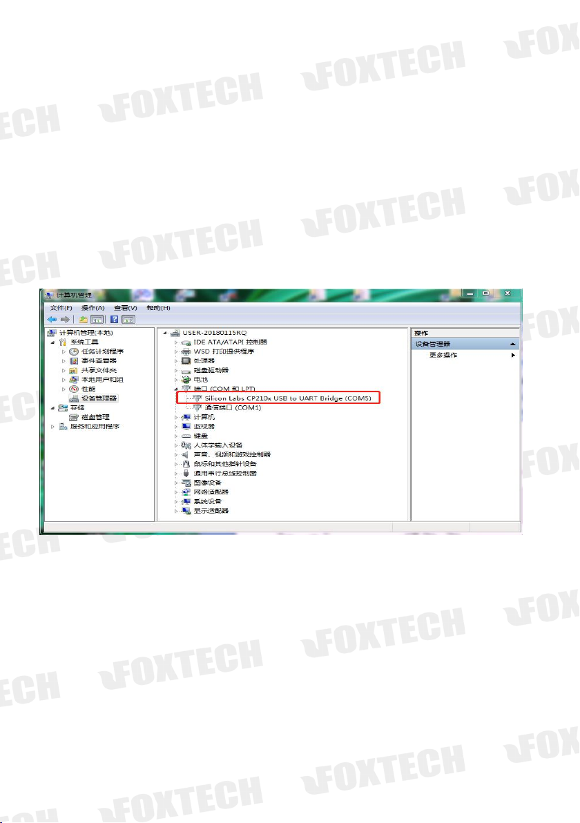
Ground terminal USB port
identification
After the radio is turned on, connect the radio and PC with the USB cable. If the
USB to serial port driver has been properly installed, the PC will display a port as
shown. If a yellow exclamation mark is displayed, the driver is not installed
correctly. Please go to our website to download the relevant driver.
Page 13

13
Wireless network selection and setup
Press and hold the set button during the boot process until the RSSI indicator RS1
flashes or RS1 and RS2 flash simultaneously, indicating that the wireless network
switching and configuration mode is entered. At this time, release the set button to
set the wireless module parameters and switch the wireless network through the
serial port AT command. For the WIFI module and Bluetooth module parameter
settings, please check the WIFI and Bluetooth parameter configuration chapters.
The following describes the switching of the wireless network, the specific method
is as follows:
Short press the PWR button to switch the wireless network. The number of flashing
RS1, RS2, and RS3 indicators indicates the wireless network type. The RS1 flashing
indicates that the current switch is WIFI, and the WIFI parameter can be set through
the USB data cable by using the serial AT command. RS1 and RS2 flash
simultaneously to indicate that the current switch is BLE, and the BLE parameter can
be set through the USB data line using the serial AT command. After the setting is
completed, press the set button to exit the setting.
WIFI Wireless Network Connection
The PC and the radio are not connected by the USB data cable, if the wireless
network selects the WIFI network, the WIFI network can be used for the serial
port link data transmission. The first time connecting to the WIFI network, you
need to connect manually. After selecting the automatic connection, as long
as the PC is within the range of the radio WIFI network, it will automatically
connect and can directly use the WiFi network communication.
Page 14

14
(1) Open the PC wireless network connection. If the radio WIFI module
works normally, it will scan the network named “D04_Radio”. The factory
default password is 88888888.
(2)After connecting to the WIFI network, the serial port link data
transmission can be performed through the TCP protocol or the virtual port
(requires WIFI virtual port tool).
1
1 If using TCP protocol for communication, open the Mission Planner
ground station, select TCP communication mode, input the radio IP
address 192.168.6.1, port number (default is 8899), establish connection
(the baud rate is not selected),
Page 15

15
2
To use the port for communication, you need to use the WIFI virtual port
tool to virtualize the WIFI network connection into a port.
Install WIFI virtual port toolkit, click “Add”, then you will see the virtual
serial interface , select an unused port, the network protocol selects the
client, and input the datalink IP and port, click OK and you will see that a
new port ELTIMA Virtural Serial Port has been added to the device
manager. This port is the virtual serial port of the WIFI network.
BLE Wireless Network Connection
In the case where the PC and the radio are not connected by the USB data
cable, if the wireless network selects the BLE network, the BLE network can be
used for the data transmission. The first time you connect to a BLE network,
you need to add and identify devices. After the first connection of the radio
BLE and the PC, as long as the PC is within the range of the radio network, it
will automatically connect and can communicate directly using the BLE
network port.
Page 16

16
1. Select a PC with BLE function, open the network connection settings, and
enable the Bluetooth network connection.
2.
Open the device and printer options on the control panel and click Add
Device. If the radio BLE module works normally, the device “D04_Radio”
will be displayed in the device list, which is the Radio BLE device.
3. After the device is added, the PC will automatically install the BLE virtual
port driver. When you open the device manager, you can see that there
are two new Bluetooth link standard serial ports on the PC. In general, the
first port is the port we want to use.
Page 17

17
Air Unit
1
②③④
⑤
⑥
⑦⑧⑨
1
Power port
support the XT30 connector,voltage:7.4-12V
2
COM port
TTL port , used to connect the FC COM port or API.
3
S-BUS1 port
Use the servo wire to connect the S-BUS interface of the flight controller or other equipment
4
S-BUS2 Port
Page 18

18
5
Use the servo wire to connect the S-BUS interface of the flight controller or other equipment
6
Signal strength
S1 S2 S3- signal strength indicator
7
High frequency module data transmission indicator
When RXD indicator is on, indicates that the receiver receives the data,TXD indicator is on means that the receiver
transmits data.
8
S-BUS data indicator L1
u
sed to indicate the communication status of S-bus signal between the ground
and air unit, and also indicate the button response while setting the Failsafe.
9
Station configuration mode indicator L2
Used to indicate whether the receiver is in the configuration mode or the
communication status of the serial port signal, and also indicates the button
response while setting the failsafe.
10
SET Button
For firmware upgrade and parameter setting.
Air Unit Diagram
1.
Tighten the antenna to the SMA connector
.
2. Fixed the air unit on the drone.
3. Connect the COM port and S-BUS on the air unit to your device using the
servo cable as shown above.
Page 19

19
RXTXS
S
receiver GND
GND FC
receiver +
+ FC
TXRX-
-
4. input stable 7.4-12V DC power.
Page 20

20
Datalink Link Communication Test
After the connection is completed, please check the connection status by following
the steps below. (This step will be partially different due to the connection method
of the ground unit or the flight control)
1.
If the ground unit is connected to PC by USB data cable , open the device
manager of the PC and check if the port is correctly identified. If you are using
Bluetooth or WIFI wireless connection, please ignore this step.
2.
Check whether the two-way S-BUS on the ground unit has signal input, check
whether the air unit flight control serial port is normally connected, and
whether the flight control enters a stable working state.
3. Open the flight control ground station software, select the corresponding
COM port, and the baud rate to connect flight control (connect by using BLE or
WIFI, the baud rate can be free, according to the specific situation). The flight
control is normally connected, indicating that the datalink has been connected.
If the connection fails, please check the following points:
1)Whether the baud rate of the flight control, air unit and ground unit is the
same. If the ground unit is connected by USB data cable, the ground station's
baud rate should also be the same. If the ground unit is connected through
WIFI, the baud rate of the wireless module must be the same.
2)If the ground unit is connected by a USB cable, make sure that the driver of
the ground unit is successfully installed.
3)Use the parameter setting software to ensure that all parameter settings on
the ground and sky are consistent.
4)Make sure that the RX of the flight control is connected to the air unit TX
port, and the TX of the flight control to the air unit RX port.
4. Open the remote control setting interface in the ground station to check
whether the remote control data is normal. For example, the remote control
data changes normally with the joystick, it means that the remote control link
is connected. If the remote control is not normally connected, please check if
the "-, +, signal" of the S-BUS is reversed.
After the ground and the air unit are activated, if the 3 signal strength indicator
5.
RS1 RS2 RS3 of ground unit and the signal strength indicator RS1 RS2 of the
air unit are always on, and the air unit signal strength indicator S3 flashes, it
means that the two modules have normally connected.
Page 21

21
Radio Parameter Configuration
The radio parameters have been set at the factory. By default, you should be able
to use the ground and air unit directly for data transmission. In the following
situations, you may need to modify the radio parameters:
1.The flight control baud rate is inconsistent with the preset baud rate
2.Multiple radios occupy the same communication channel, and the
communication is blocked.
3.Have special communication bandwidth and communication power
requirements.
Ground unit connection and enter configuration mode:
Please follow the steps below to modify the parameters:
1. Follow the steps below to enter the parameter configuration mode. The
parameter modification method of ground unit and air unit is basically the same.,
except that the connection cable is different.
Ground unit connection and access to configuration mode:
1 Press and hold the SET button, then turn it on until RS1 or RS1 and RS2
flash, then enter the wireless network selection mode.
2 In wireless network selection mode, release the SET button, then press the
SET button again, until the config light is on, then release the button, and
enter the high-frequency module configuration mode.
3 Connect the radio and PC with the USB cable according to the connection
method shown below.
Air unit connection and enter configuration mode:
1 Connect the air unit and PC, press and hold the SET button, power on until
the L2 light is on, then release the button.
2 Connect the air unit and PC , Note that the white configuration wire
corresponds to the TX of the air unit, the black wire corresponds to GND,
Page 22

22
and the green wire corresponds to RX.
1、 Please check your radio is H840 or P900, then use the matching assistant
software to view and modify the parameters through the port. (If the
corresponding port is not found, please check if the corresponding serial port
driver is properly installed.)
1
If your radio is H840, use the matching assistant software ,select the
corresponding port and click the connection to read the radio parameter,
as shown below:
若想修改电台参数,只需在软件中改变相应的值,点击写入,并确定即可,如下
图 所 示 If you want to modify the radio parameters, just change the
Page 23

23
corresponding value in the software, click on “write”, and then confirm,
as shown below:
2
If your radio is P900 version, please open the corresponding assistant
software ,Select the appropriate port and click Connect. The current
baud rate of the serial port link will be displayed. Pull down to select the
desired baud rate as the serial link baud rate.
If you want to modify the radio's ID (address) and output power, please
follow the steps below:
a) Click , will read out the basic parameters of the high frequency
module.
Page 24

24
b) After filling in the address and selecting the output power,first click
then click Disconnect. (Do not modify other values during this
process, as this may cause the station to be unable to communicate
Note: When configuring parameters, the air unit address and the
corresponding position baud rate should be consistent with the ground
unit, otherwise the radio may not communicate.
2、 After the modification is completed, short press the SET button or power on
again to exit the configuration mode.
Note:
If the high frequency parameters of the ground unit and the air unit are
inconsistent, the two modules may cannot communicate.
Communication bandwidth and communication power directly affect
communication quality and communication distance. If you don't understand
its meaning, please do not modify these two parameter values.
After entering the configuration mode to complete the parameter
configuration, then be sure to exit the configuration mode.
Page 25

25
High frequency module H800 pairing parameter instructions
Name
Modification
Range
Note
Address
(ID)
random
0-65535
用于接收机和遥控器之间配对的
唯一 ID 码
Baud rate
manual
1200、2400、4800、9600、
19200、3400、57600、
115200
This baud rate needs to be set
according to the baud rate required
by FC(Default 115200)
Channel
manual
1-8
Bandwidth
manual
100K、200K
Default 100K , The greater the
bandwidth, the closer the
communication distance
Power
manual
30DBM 1W
29DBM 0.8W
27DBM 0.5W
24DBM 0.25W
20DBM 0.1W
Default 1W,The greater the power,
the farther the communication
distance
名 称
修改方式
数值范围
备 注
address(ID)
random
0-65535
用于接收机和遥控器之间配对的
唯一 ID 码
Baud rate
Not allow
Fixed value 115200
This baud rate is the baud rate of
communication between high
frequency modules, not the serial link
baud rate. Serial port baud rate need
to be set separately
Working mode
Not allow
Master or Slave
Air unit-Master,ground unit-Slave
Bandwidth
mal
100K、200K
Default 100K,The greater the
bandwidth, the closer the
communication distance
power
manual
30DBM 1W
29DBM 0.8W
27DBM 0.5W
24DBM 0.25W
20DBM 0.1W
Default 1W,The greater the power,
the farther the communication
distance
High frequency module P900 pairing parameter instructions
Page 26

26
Ground Unit Battery Charging
The D04 module is equipped with a 3000mAH lithium battery. Under normal
working conditions, the battery can be used for about 15h. If the battery indicator
shows a low voltage, please charge the battery in time.
Insert the standard adapter of the ground unit into the 220V socket, and connect
the output port to the battery charging port. When the indicator light changes
from red to green, the battery is fully charged.
Note:
Please charge with the factory-standard adapter, and do not charge with other
types of chargers. The USB port Type-C can only be used for data transmission, can
not be used for battery charging.
Page 27

27
Radio Alarm
Radio low-voltage alarm: When the D04 radio voltage is too low (below 10.6V),
the system will give an alarm. And the PWR indicator will flash, and with the buzzer
sound continuously for a short time. If prompted, please charge the battery in time
to avoid affecting the use
Radio low-voltage alarm recovery: Under the condition of radio low-voltage alarm,
if the radio is charged in time to restore the power (10.9V), the radio low-voltage
alarm indicator and buzzer will be automatically eliminated.
Radio low-voltage shutdown: When the radio low-voltage alarm, if the radio is not
charged in time, the radio power will continue to decrease. When the power is
reduced to a certain level (below 10.3V), in order to protect battery life and system
data, the system will save data and then has a forced shutdown operation.
Radio cooling and high temperature alarm: The radio has integrated heat
dissipation interface, which can be connected to the 5V fan to dissipate heat from
the system. If your radio is equipped with a fan, the system will turn on the fan to
dissipate heat when the temperature is greater than 50 °C. If the temperature is
too high (up to 80 ° C), the system will prompt you. At this time, the four battery
indicator lights flash at the same time, and the buzzer sounds continuously for a
short time. If prompted, to avoid accidents, please stop using the radio
immediately.
Page 28

28
Failsafe Setting
The failsafe of the D04 radio is set on the Air unit. If you need to set the remote
control's failsafe, please operate as follow:
1、 Write to failsafe data and open the failsafe function.
When the air unit is properly connected to the ground unit, short press the
SET button on the air unit (the L1 and L2 indicators will be on for about 1
second after being released), the 1-way or 2-way S-BUS signal currently being
transmitted can be stored as the failsafe value in the air unit, and the data will
not be lost after power off.
Please test through the flight control ground station or the servo, to see
whether the Failsafe data is successfully written or not.
Trigger Failsafe Value
When the air unit does not receive the S-BUS data from the ground unit for 3
seconds, the air unit will continue to output the previously set Failsafe value
until received the S-BUS data from ground unit.
2、
Close Failsafe Function
When the air unit is properly connected to the ground unit, press and hold the
SET button on the air unit (about 5s) until the L1 and L2 indicators are on at
the same time (about 1 second) to close the failsafe function of 1 or 2 way
S-BUS signal which is being transmitted, and the data will not be lost after
power-off. After the Failsafe function is closed, if the air unit does not receive
the S-BUS signal from ground unit for a long time, it will keep outputting the
last data. Please through the flight control ground station or the servo to test
whether the setting is successful.
Note:
The default Failsafe function is closed.
Page 29

29
WiFI Module Parameter Setting
If you need to set the serial port baud rate and WIFI network parameters, please
operate as follows:
1、 Use PC to search and connect WIFI network generated by WIFI module
2、 Log in to the server, modify the parameters
Open the browser, enter the module's IP address in the address bar (the
factory default address is http://192.168.6.1), press Enter, enter the login user
name and password in the pop-up interface (the default user name and
password at the factory: admin), log in to the module configuration interface.
In the WIFI parameter field, you can modify the network name SSID and
password when necessary.
Page 30

30
To change the baud rate of radio serial port , you can modify the parameters
as needed in the UART parameter field.
The Socket parameter setting is attached to the UART parameter bar, it can be
used to change the server address and port number. This address and port
number is what we used in TCP communication or virtual serial port.
In the account management column, you can modify the webpage login
information.
Page 31

31
In the recovery restart bar, you can restore the WIFI module parameters to the
factory default parameters.
Note: Click “Save” after the parameters in current column are changed, and
the changed parameters will take effect after the page is restarted or the
ground unit is turned off and restarted.
Page 32

32
The WIFI module parameters can also be configured through the serial port AT command. The
WIFI module AT Commands
Instruction
Note
AT+WEBU
Query web login username and password
AT+WMODE
Query WiFi working mode
AT+WAP
Query the AP's WiFi network name and
password.
AT+WSTA
Query the SSID and password of the
associated AP.
AT+UART
Query UART interface parameters
300~3Mbps
AT+SEARCH
Query LAN search port and keywords
AT+MID
Query module MID
AT+WEBU=admin,admin
Set web login username and password
AT+WMODE=AP
Set WiFi working mode
AP mode,STA mode
AT+WAP=D04-Radio,88888888
Set the AP's WiFi network name and
configuration process is as follow:
1、 Press and hold the SET button during the boot process until the RSSI indicator RS1 flashes
or RS1 and RS2 flash simultaneously, indicating that the wireless network switching and
configuration mode is entered. At this time, release the SET button to set the wireless
module parameters and switch the wireless network. Short press the PWR button, switch
wireless network to WIFI mode.
2、
Connect the radio and PC with USB data cable, open the serial debugging assistant, the
baud rate is the actual value of the current WIFI serial port baud rate (if you forget the
parameters, you can short press the SET button to exit the parameter configuration after
the wireless network switches to WIFI mode, In the normal working state of D04 module,
you can restore the WIFI parameters to the factory default values and then modify the
parameters. And then a series of operations are required to read and write parameters of
the WIFI module.
a) Send "+++" to the module continuously (no carriage return line feed). After the
module receives "+++", it will send back an ‘a’.
b) After receiving ‘a’ (no carriage return), the module must be sent an ‘a’ within 3
seconds.
c) After receiving the ‘a’, the module will send “+ok”, indicating that the AT command
mode has entered successfully. Parameter reading and writing of WIFI module
can be realized through AT command.
d) The table below lists some commonly used AT commands, all ending with a carriage
return. Restart after the parameter is set.
Page 33

33
password.
AT+WSTA=D04-Radio,NONE
Set the SSID and password of the
associated AP.
AT+UART=115200,8,1,NONE,NFC
Query UART interface parameters
Buad rate 115200, Data bit 8, stop
bit 1, no parity, no flow control
AT+SEARCH=48899,chinowing
Set LAN search port and keywords
AT+MID=D04
Set module MID
Within 20 characters
AT+CFGTF
Store current usage parameters as user
default parameters
AT+RELD
Restore module parameters to user
default parameters
Restore factory settings
AT+Z
Restart module
AT+ENTM
Exit command mode
Return to transparent mode by
default
3、 After configuring the parameters, shrot press the set button to exit the
wireless network switching and configuration mode.
Page 34

34
BLE Module Parameter Setting
BLE module AT
commands
Instruction
Note
AT+BNAME?
Query module BLE network name
AT+SNAME?
Query module SPP network name
AT+UART?
Query the serial port baud rate
AT+HELLO?
Query welcome languag
AT+TPL?
Query module transmit power
AT+MODE?
Query module working mode
Since the BLE module does not have a corresponding PC software
configuration,
for
it can only be configured through the serial port AT command. Therefore, it is
generally not recommended to change the BLE module parameters. If you really
need to change the BLE module parameter settings, please do as following:
1. Press and hold the Set button during the boot process until the RSSI indicator RS1
flashes or RS1 and RS2 flash simultaneously, that indicates the wireless network
switching and configuration mode is entered. At this time, release the Set button to
set the Bluetooth parameters and switch the wireless network. Short press the PWR
button and the Wireless network will be switched to BLE mode.
2. Connect the radio and PC with USB data cable, open the serial debugging assistant,
the baud rate is the actual value of the current BLE serial baud rate (if you forget the
parameters, you can restore the parameters to the factory default value and then
modify the parameters) At this time, a series of operations are required to read and
write parameters of the BLE module.
a) Send "+++" to the module continuously (no carriage return line feed). After
the module receives "+++", it will send back an ‘a’.
b) After receiving ‘a’ (no carriage return), the module must be sent an ‘a’
within 3 seconds.
c) After receiving the ‘a’, the module will send “+ok”, indicating that the AT
command mode has entered successfully. Parameter reading and writing of
BLE module can be realized through AT command.
d) The table below lists some commonly used AT commands, all ending with a
carriage return. Restart after the parameter is set.
Page 35

35
AT+BNAME=D04_Radio
Set the module BLE network name as D04_Radio
The name of the module (limit length 1~10
bytes)
AT+SNAME=D04_RADIO
Set the module SPP network name as D04_RADIO
The name of the module (limit length 1~10
bytes)
AT+UART=115200
Set the serial port baud rate to 115200
9600~3Mbp
AT+HELLO=D04_Radio
Set module welcome language D04_Radio
欢迎语(限制长度 0~10 字节)
AT+TPL=10
Set the module transmit power to 10dbm
transmit power(-25dBm~10dBm)Restart to
take effect
AT+MODE=S
Set to slave mode (S: slave mode SLAVE; T: master
mode SPP_MAST; B: master mode BLE_MAST)
AT+CFGTF
Save the current parameter as the user default
parameter
AT+RELD
Restore current parameters to user default
parameters (restore factory default)
The same effect as Hardware nReload pin
is pulled low for more than 3s
AT+Z
Restart the module system
AT+ENTM
Exit AT command mode and return to transparent mode
3. After configuring the parameters, press the Set button to exit the wireless
network switching and configuration mode.
Page 36

36
BLE and WIFI Modules are Restored to Factory
Settings
When the ground unit is in normal working condition, press and hold the SET button for 5s
until all the power indicator lights flash at the same time to force the current wireless network
module to reset to the factory settings and restart. After restoring the factory settings, the
configuration of all users of the WIFI module will be changed to the factory default parameters.
1. The default parameters of the WIFI module:
Network name SSID: D04-Radio.
Password:88888888.
Network mode: AP mode.
IP address: 192.168.6.1.
Serial port 0 baud rate: 115200, 8N1.
2. Default parameters of the BLE module:
Network name: D04-Radio.
Serial port baud rate: 115200, 8N1.
Module transmit power: +10dBm
Page 37

37
Check the Radio System Firmware
Version
In order to provide better service to our customers, our R&D team has never stopped testing the
products. Once we found the bug in software firmware, we will upgrade the software firmware
optimize it in time, and the latest software firmware will be released to the website, so please
note the software firmware version before using. Please pay attention to our website to get the
latest software firmware and technical support.
The version of the assistant software can be seen directly when configuring the parameters on
the PC. Please check the firmware version by the following steps:
1. Connect the radio to the PC via the USB cable, and a port will appear on the PC.
2. Install the serial debugging assistant on the PC and open this port.
Port configuration parameters: 115200, 8N1. String display mode
3.During the process of starting the radio, the serial port assistant will print the following
firmware version information "JDSP4-0.5.1---JDSP4-1.20"
The JDSP4 indicates the P900 version of the D04 radio (JDSH4 indicates the H800 version of the
D04 radio). The first version number indicates the soft version number of the firmware, and the
second version number indicates the hard version number of the firmware. The version number
above indicates that this radio is the P900 version of the D04 radio, where the soft version
number is 0.5.1 and the hard version number is 1.20.
Page 38

38
Firmware Upgrade Steps
Please use the firmware upgrade tool to upgrade the firmware of radio ground unit
and air unit separately.
Ground unit Firmware upgrade
1. Click firmware download on the official website , select the appropriate
version of the firmware and save the firmware locally.
2. Close other applications that use the port, open the firmware upgrade tool
3. Connect the radio to the PC with a USB cable and a port number will be
displayed in the device manager.
Page 39

39
4. Press and hold the Set button and turn it on at the same time until
RS1 flashes (or RS1 and RS2 flash simultaneously). Release the set
button, indicating that the wireless network selection mode is entered.
At this time, you can select the wireless communication method.
5. In the wireless network selection mode, press and hold the set button
again until the config light is on, and release the set button, indicating
that you have entered the high-frequency module configuration
mode . At this point, you can configure the data transmission module
parameters.
6. In the high-frequency module configuration mode, press and hold
the set button again until the config light is off and the PWR light
starts to flash. Release the set button and enter the firmware upgrade
mode. At this point you can upgrade the firmware.
7. After entering the firmware upgrade mode, you can see that the firmware
upgrade tool has been connected to the radio and display the current
hardware, version and other information of the radio, as shown below:
8. Open the path of the firmware file you just saved. The upgrade tool will
display the hardware and version information of the selected firmware. If the
selected firmware hardware version does not match the current radio
hardware version, the upgrade tool will prompt an error, so please select the
correct firmware. If the firmware information matches, the upgrade tool will
display ‘ recognition completion’ and wait for the upgrade.
Page 40

40
9. Click the “Start Upgrade” button after confirmation, and then firmware starts
writing.
10. Firmware starts writing
11. Wait for the firmware upgrade until the firmware upgrade completion prompt
dialog box is displayed, then close the window of firmware upgrade tool.
Firmware has been successfully upgraded.
Page 41

41
Receiver firmware upgrade
The firmware upgrade method of the receiver is similar to the ground unit except
the way to enter the firmware upgrade mode.
1. Click firmware download on the official website , select the appropriate version
of the firmware and save the firmware locally.
2. The receiver is powered off and connect the COM port of the receiver to the
computer via the receiver wire.
3. Make sure the assistant software is closed and open the firmware upgrade tool.
4. Press and hold the receiver set button and power on the receiver at the same
time.
5. Release the button to see that the indicator L2 is on.
6. Press and hold the button again until the indicator L1 is on and then release the
button. At this moment, you can see that the serial port of the firmware upgrade
tool is connected, and the current version, firmware and other information of the
Page 42

42
receiver are displayed.
7. Open the path of the firmware file you just saved and click the Start button after
confirmation.
8. Wait for the firmware upgrade until the firmware upgrade completion prompt
dialog box is displayed, then close the window of firmware upgrade tool. Firmware
has been successfully upgraded.
Please strictly follow the operation steps to ensure that other software that
uses the port, such as the serial debugging assistant, is turned off to release
the port. Otherwise, the upgrade may fail.
Please select the corresponding firmware. If the firmware does not match,
the upgrade will fail.
Page 43

43
FAQ
1 : The receiver S-BUS has a signal output, but the serial port cannot be
connected, or the transmission signal is garbled.
Please check whether the serial port baud rate of the air unit and the ground
unit is the same; and set the baud rate corresponding to the ground station
software.
2:
Two or more devices have interference turned on at the same time.
Please check that the ID of each set must be different, and the channel
should also be set to different values to avoid interference.
 Loading...