

Page 1

Operations
Manual
Thermal Jet
Ink Jet System
1 Missouri Research Park Drive • St. Charles, MO 63304 • 1-800-369-5384
5780-329
Revision J
Illinois Tool Works Inc © 2010
Page 2

Operations Manual
Ink Cartridge: The SoloSeries has been engineered
and designed to work with Foxjet ink cartridges. The
SoloSeries’ Smart Level Ink Detection System,
which provides ink level monitoring to ensure complete ink usage and product safety, will not be functional if used with non-Foxjet ink cartridges.
Thermal Jet
Ink Jet System
5780-329
Revision J
The information contained in this manual
is correct and accurate at the time of its
publication. Foxjet reserves the right to
change or alter any information or
technical specifications at any time and
without notice.
©2010 Illinois Tool Works Inc.
All rights reserved
Printed in the United States of America
Page 3

Thermal Jet
Warranty:
The SoloSeries Thermal Jet system, including all components unless otherwise
specified, carries a limited warranty.
The inks and conditioners used with the SoloSeries Thermal Jet system carry a limited
warranty.
For all warranty terms and conditions, contact Foxjet an ITW Company for a complete
copy of the Limited Warranty Statement.
Page 4

Thermal Jet
Section 1: Safety and Ink Cartridge Usage . . . . . . . . . . . . . . . . . . . . . . . . . . . . . . . . . . . . . . . . 1
Section 2: Quick Start .. . . . . . . . . . . . . . . . . . . . . . . . . . . . . . . . . . . . . . . . . . . . . . . . . . . . . . . . . 2
Step 1: Assemble Bracketry . . . . . . . . . . . . . . . . . . . . . . . . . . . . . . . . . . . . . . . . . . . . . . . . 3
Step 2: Assemble Bracketry to Conveyor .. . . . . . . . . . . . . . . . . . . . . . . . . . . . . . . . . . . . . 3
Step 3: Assemble SoloSeries Print Head and Power Supply to Bracketry .. . . . . . . . . . . . 4
Step 4: Adjust SoloSeries Print Head to Substrate . . . . . . . . . . . . . . . . . . . . . . . . . . . . . . . 5
Step 5: Insert Cartridge Pen into Print Head .. . . . . . . . . . . . . . . . . . . . . . . . . . . . . . . . . . . 6
Step 6: Cabling, Power, and Serial Port Setup . . . . . . . . . . . . . . . . . . . . . . . . . . . . . . . . . . 7
Step 7: Configure the Print Head . . . . . . . . . . . . . . . . . . . . . . . . . . . . . . . . . . . . . . . . . . . 10
Step 8: Create a Message . . . . . . . . . . . . . . . . . . . . . . . . . . . . . . . . . . . . . . . . . . . . . . . . . 11
Step 9: Print a Message .. . . . . . . . . . . . . . . . . . . . . . . . . . . . . . . . . . . . . . . . . . . . . . . . . . 12
Section 3: Marksman HHI or GUI Functionality . . . . . . . . . . . . . . . . . . . . . . . . . . . . . . . . . . 13
Keypad or Keyboard .. . . . . . . . . . . . . . . . . . . . . . . . . . . . . . . . . . . . . . . . . . . . . . . . . . . . 13
Home Screen .. . . . . . . . . . . . . . . . . . . . . . . . . . . . . . . . . . . . . . . . . . . . . . . . . . . . . . . . . . 14
Main Menu . . . . . . . . . . . . . . . . . . . . . . . . . . . . . . . . . . . . . . . . . . . . . . . . . . . . . . . . . . . . 16
Print Menu . . . . . . . . . . . . . . . . . . . . . . . . . . . . . . . . . . . . . . . . . . . . . . . . . . . . . . . . . . . . 16
Messages Dialog & the Message Editor . . . . . . . . . . . . . . . . . . . . . . . . . . . . . . . . . . . . . . 16
Control Panels Menu . . . . . . . . . . . . . . . . . . . . . . . . . . . . . . . . . . . . . . . . . . . . . . . . . . . . 22
Time & Date Setting Screens . . . . . . . . . . . . . . . . . . . . . . . . . . . . . . . . . . . . . . . . . . . . . . 24
Status Screen. . . . . . . . . . . . . . . . . . . . . . . . . . . . . . . . . . . . . . . . . . . . . . . . . . . . . . . . . . . 25
Section 4: Maintenance & Shutdowns . . . . . . . . . . . . . . . . . . . . . . . . . . . . . . . . . . . . . . . . . . . 26
Daily Maintenance, Ink Cartridge . . . . . . . . . . . . . . . . . . . . . . . . . . . . . . . . . . . . . . . . . . 26
Weekly to Monthly Maintenance, Print Head . . . . . . . . . . . . . . . . . . . . . . . . . . . . . . . . . 27
Shutdowns Less Than 3 Days .. . . . . . . . . . . . . . . . . . . . . . . . . . . . . . . . . . . . . . . . . . . . . 27
Shutdowns More Than 3 Days . . . . . . . . . . . . . . . . . . . . . . . . . . . . . . . . . . . . . . . . . . . . . 27
Section 5: Troubleshooting . . . . . . . . . . . . . . . . . . . . . . . . . . . . . . . . . . . . . . . . . . . . . . . . . . . . 28
Appendix A: Specifications . . . . . . . . . . . . . . . . . . . . . . . . . . . . . . . . . . . . . . . . . . . . . . . . . . . . 29
SoloSeries45 . . . . . . . . . . . . . . . . . . . . . . . . . . . . . . . . . . . . . . . . . . . . . . . . . . . . . . . . . . . 29
SoloSeries90 . . . . . . . . . . . . . . . . . . . . . . . . . . . . . . . . . . . . . . . . . . . . . . . . . . . . . . . . . . . 30
SoloSeries IS. . . . . . . . . . . . . . . . . . . . . . . . . . . . . . . . . . . . . . . . . . . . . . . . . . . . . . . . . . . 31
Marksman HHI . . . . . . . . . . . . . . . . . . . . . . . . . . . . . . . . . . . . . . . . . . . . . . . . . . . . . . . . . 32
Appendix B: Theory of Operation . . . . . . . . . . . . . . . . . . . . . . . . . . . . . . . . . . . . . . . . . . . . . . 33
SoloSeries Print Heads . . . . . . . . . . . . . . . . . . . . . . . . . . . . . . . . . . . . . . . . . . . . . . . . . . . 33
Marksman HHI. . . . . . . . . . . . . . . . . . . . . . . . . . . . . . . . . . . . . . . . . . . . . . . . . . . . . . . . . 34
Interconnect Diagram . . . . . . . . . . . . . . . . . . . . . . . . . . . . . . . . . . . . . . . . . . . . . . . . . . . . 38
Appendix C: Part Numbers - Consumables and Service Parts . . . . . . . . . . . . . . . . . . . . . . . 39
Consumables .. . . . . . . . . . . . . . . . . . . . . . . . . . . . . . . . . . . . . . . . . . . . . . . . . . . . . . . . . . 39
Service Parts . . . . . . . . . . . . . . . . . . . . . . . . . . . . . . . . . . . . . . . . . . . . . . . . . . . . . . . . . . . 39
Optional Equipment . . . . . . . . . . . . . . . . . . . . . . . . . . . . . . . . . . . . . . . . . . . . . . . . . . . . . 42
5780-329 Operations Manual Rev J
Page 5

Thermal Jet
Appendix D: File Backup and Restore . . . . . . . . . . . . . . . . . . . . . . . . . . . . . . . . . . . . . . . . . . . 44
File Backup . . . . . . . . . . . . . . . . . . . . . . . . . . . . . . . . . . . . . . . . . . . . . . . . . . . . . . . . . . . . 45
Restoring Backed-Up Files .. . . . . . . . . . . . . . . . . . . . . . . . . . . . . . . . . . . . . . . . . . . . . . . 46
Appendix E: Configuring a PC to Communicate with the IJ3000-ES .. . . . . . . . . . . . . . . . . 47
Windows XP® . . . . . . . . . . . . . . . . . . . . . . . . . . . . . . . . . . . . . . . . . . . . . . . . . . . . . . . . . 47
Windows 2000® . . . . . . . . . . . . . . . . . . . . . . . . . . . . . . . . . . . . . . . . . . . . . . . . . . . . . . . . 49
Appendix F: Font Samples .. . . . . . . . . . . . . . . . . . . . . . . . . . . . . . . . . . . . . . . . . . . . . . . . . . . . 51
Appendix G: Creating Logo Files . . . . . . . . . . . . . . . . . . . . . . . . . . . . . . . . . . . . . . . . . . . . . . . 52
Appendix H: Uploading Files to the Print Head and File Management . . . . . . . . . . . . . . . . 54
Appendix I: Communicating Directly to the Print Head . . . . . . . . . . . . . . . . . . . . . . . . . . . . 59
Appendix J: Aligning the 1" (25.4 mm) Print Head . . . . . . . . . . . . . . . . . . . . . . . . . . . . . . . . 60
Appendix K: SoloSeries IS Bulk Ink System . . . . . . . . . . . . . . . . . . . . . . . . . . . . . . . . . . . . . . 61
5780-329 Operations Manual Rev J
Page 6

Thermal Jet Section 1: Safety and Ink Cartridge Usage
Section 1: Safety and Ink Cartridge Usage
Following is a list of safety symbols and their meanings, which are found throughout this
manual. Pay attention to these symbols where they appear in the manual.
Wear safety goggles when performing the procedure described!
!
!
Caution or Warning! Denotes possible personal injury and/or damage to the equipment.
Caution or Warning! Denotes possible personal injury and/or equipment damage due to
electrical hazard.
NOTE: (Will be followed by a brief comment or explanation.)
ESD protection should be worn when servicing internal printed circuit boards.
After service to the equipment is completed, replace all protective devices such as ground-
ing cables and covers before operating the equipment.
It is extremely important to:
• Clean up all spills with the appropriate solvents immediately and dispose of all waste according
to local and state regulations.
• Wear safety glasses and protective clothing, including gloves, when handling all inks and conditioners.
• Store inks and solvents under the recommended conditions found on the MSDS (Material
Safety Data Sheet).
Ink Cartridge: The SoloSeries has been engineered and designed to work with Foxjet ink
cartridges. The SoloSeriess’ Smart Level Ink Detection System, which provides ink level
monitoring to ensure complete ink usage and product safety, will not be functional if used
with non-Foxjet ink cartridges.
5780-329 Operations Manual Rev J Page 1
Page 7

Thermal Jet Section 2: Quick Start
Optional Marksman HHI
controller
Section 2: Quick Start
Contents:
• SoloSeries Print Head
• Bracketry Kit
• Power Supply, 15 V
• Power Supply Bracket
•Power Cord
• Software CD
TYPICAL INSTALLATION
5780-329 Operations Manual Rev J Page 2
Page 8
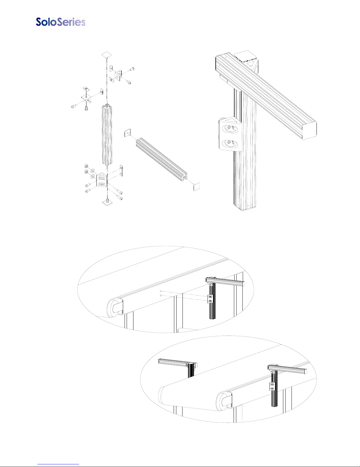
Thermal Jet Section 2: Quick Start
Step 1: Assemble Bracketry
Step 2: Assemble Bracketry to Conveyor
5780-329 Operations Manual Rev J Page 3
Page 9
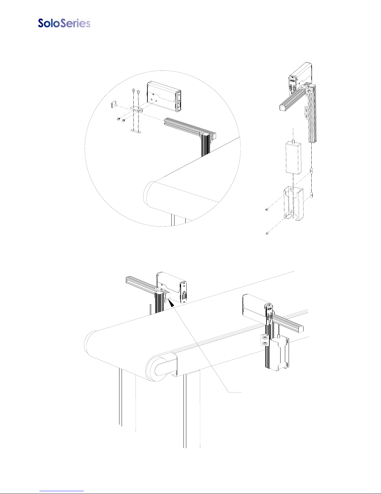
Thermal Jet Section 2: Quick Start
Ensure bar is
behind front
face of print head
Step 3:Assemble SoloSeries Print Head and Power Supply to
Bracketry
5780-329 Operations Manual Rev J Page 4
Page 10
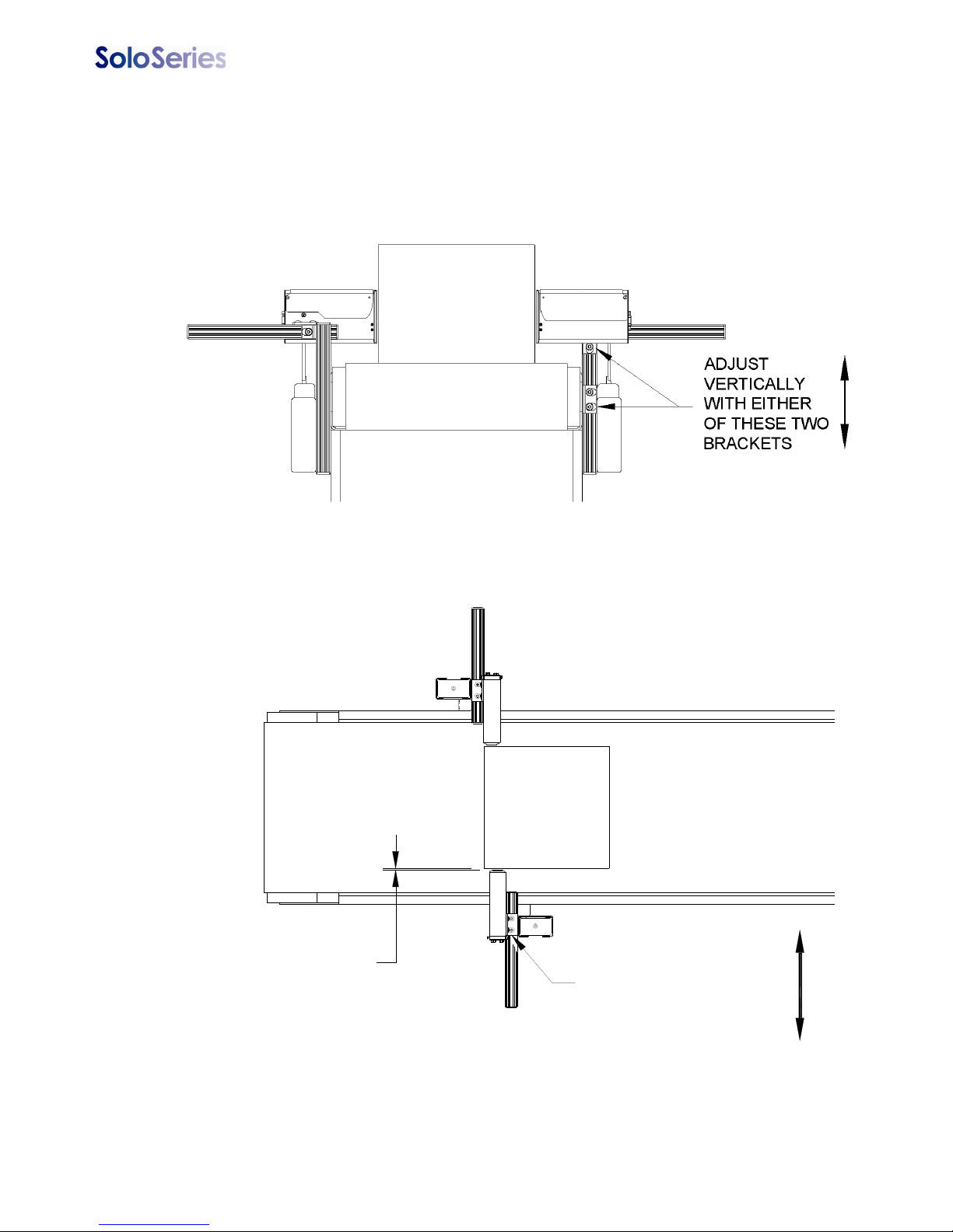
Thermal Jet Section 2: Quick Start
ADJUST THE PRINT
HEAD TO THE
SUBSTRATE WITH
THIS BRACKET
.1" (2.5mm) GAP
RECOMMENDED
Step 4: Adjust SoloSeries Print Head to Substrate
Adjust print head vertically to meet requirement.
Adjust print head horizontally to set print gap.
5780-329 Operations Manual Rev J Page 5
Page 11
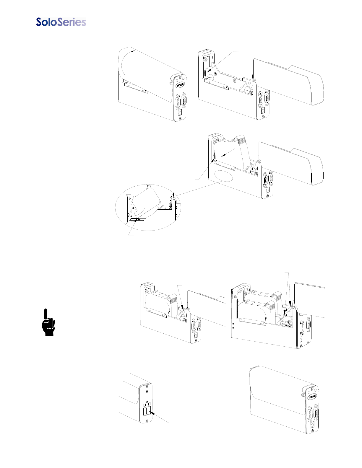
Thermal Jet Section 2: Quick Start
PEN STOP
When inserting cartridge, aim nose at an
angle towards black pogo pin component.
Slide pen cartridge up to Pen Stop.
PEN STOP
After pen cartridge
is installed
FINGER RELEASE T AB
FINGER RELEASE TABS
Step 5: Insert Pen Cartridge into Print Head
Rotate Cover
Open
Insert Pen Cartridge at an angle up to
Pen Stop
Rotate Pen Cartridge
down until it snaps in
place.
NOTE: The pen is
released by pressing
down on the Finger
Release Tab and pulling up on the rear of
the cartridge.
Close Cover
5780-329 Operations Manual Rev J Page 6
Page 12

Thermal Jet Section 2: Quick Start
COM PORT
PC OR LAPTOP
Marksman HHI
Step 6: Cabling, Power, and Serial Port Setup
Cabling
CAUTION: Power should be disconnected from the print head prior to connecting or disconnecting any external device, including: PC, controller, or print head daisy chain cables.
Electrical arcing may occur if external cabling is connected or disconnected while power is
supplied to the unit.
Print heads are controlled via a COM port from a PC or an Marksman HHI controller. One
com port can control up to eight SoloSeries45 print heads, four SoloSerie90 print heads, or
any combination of the two totalling eight print cartridges. Using the supplied serial cables,
connect the print heads daisy chain style by connecting the output port of one print head to
the input port of the next. Then connect the COM port of the PC or Marksman HHI to the
daisy chain. A PC connects to the first head in the daisy chain, while a Marksman HHI connects to the last.
5780-329 Operations Manual Rev J Page 7
Page 13
Thermal Jet
Power
CAUTION: Power should be disconnected from the print head prior to connecting or disconnecting any external device, including: PC, controller, or print head daisy chain cables.
Electrical arcing may occur if external cabling is connected or disconnected while power is
supplied to the unit.
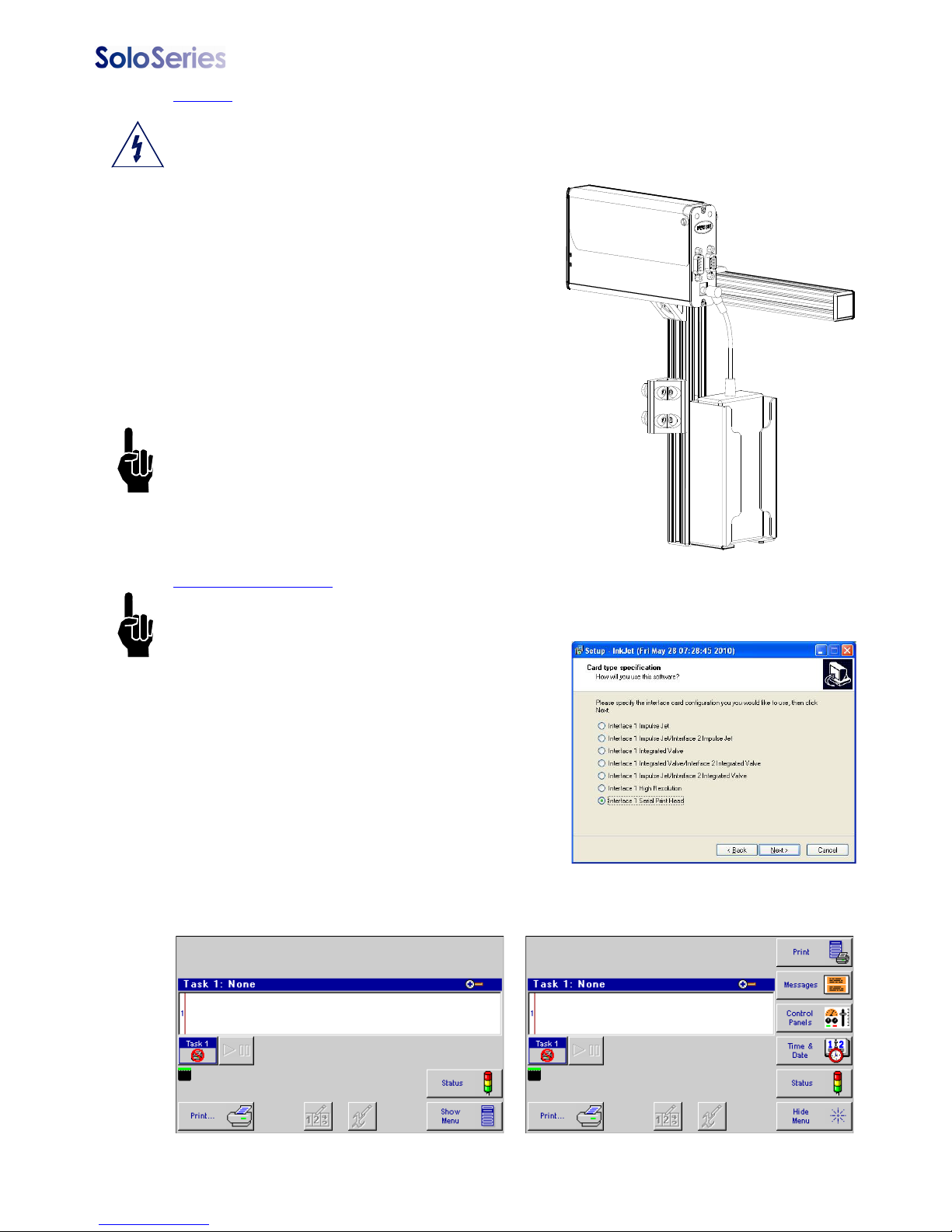
Install the power plug from the previously mounted
power supply into the power jack on the rear of
each SoloSeries print head.
Press and hold the "PURGE" button on the rear of
the print head while slowly moving a piece of
paper, cardboard, or comparable material in front
of the print cartridge. Print several purge images
and validate that all channels are printing. If not,
refer to “Section 4: Maintenance & Shutdowns” on
page 26.
NOTE: Do not rub the print cartridge face with
the print sample material as this will scratch
the orifice array and affect print quality.
The power supply for the Marksman HHI or the
computer may now be installed.
Serial Port Setup
NOTE: Depending on GUI /Marksman HHIstatus, this step may already be complete.
If a computer will be used, install the SoloSeries/
Marksman HHI GUI PC software using the CD
included with the print head. Follow the installation
prompts, and at this prompt, select "Interface 1
Serial Print Head".
After the GUI program has been installed, launch
the program.
Ensure the home screen menu is present via the Hide Menu / Show Menu button, and
then press the Control Panels button.
5780-329 Operations Manual Rev J Page 8
Page 14
Thermal Jet
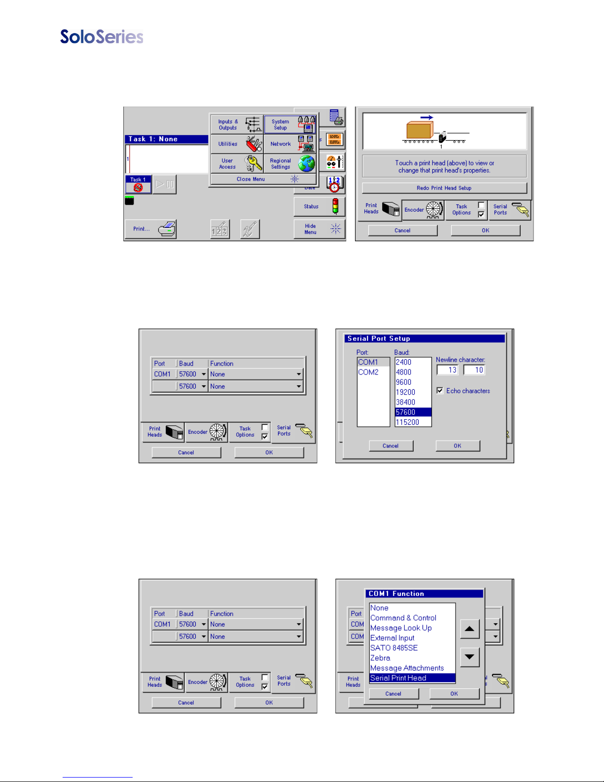
Press the System Setup button, and then the Serial Ports tab.
To ensure the baud rate is set for 57600, press the button beneath the Port/Baud column
and adjust if necessary. Press the OK button to exit the Serial Port Setup screen.
If "Serial Print Head: Task x" is not shown on theCOM1 Function button, press the button
and select the Serial Print Head option. Press the OK button to exit the COM 1 Function
screen. Press OK again to exit the System Setup screen.
5780-329 Operations Manual Rev J Page 9
Page 15
Thermal Jet
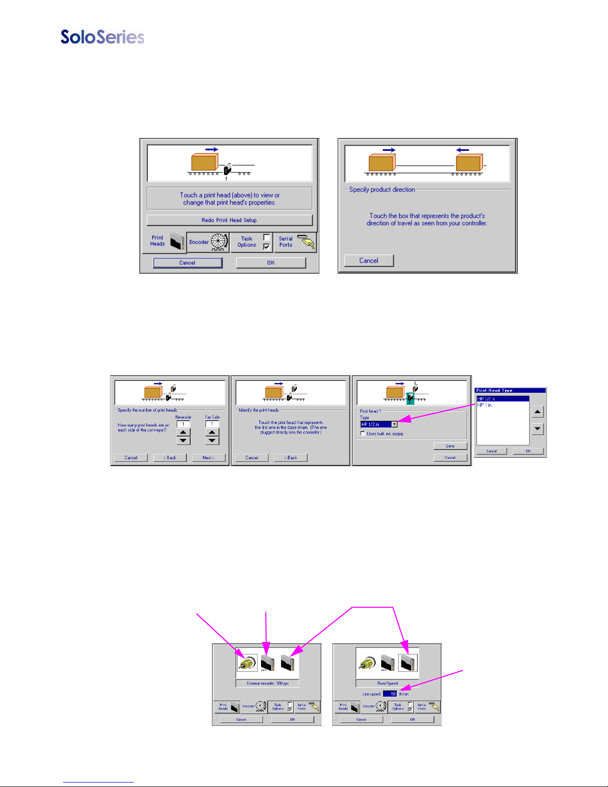
Step 7: Configure the Print Head
On the home screen, press the Control Panels button, and then press the System Setup
button. On the Print Heads page press the Redo Print Head Setup button. Select the
desired direction.
Select the number of print heads, identify the first in the daisy chain, and select the appropriate print head type by touching each one and then the drop down box.
Print head setup complete. Next, select the Encoder tab, and choose the desired encoder
type.
External Encoder:
Line speed measured by
an externally mounted
encoder and connected
to the last print head in
the daisy chain
Auto Speed Detect:
Line speed
automatically detected
via SoloSeries
photocells
Fixed Speed:
User types in the
desired line speed
5780-329 Operations Manual Rev J Page 10
Touch this
box, then type
in the desired
speed
Page 16
Thermal Jet
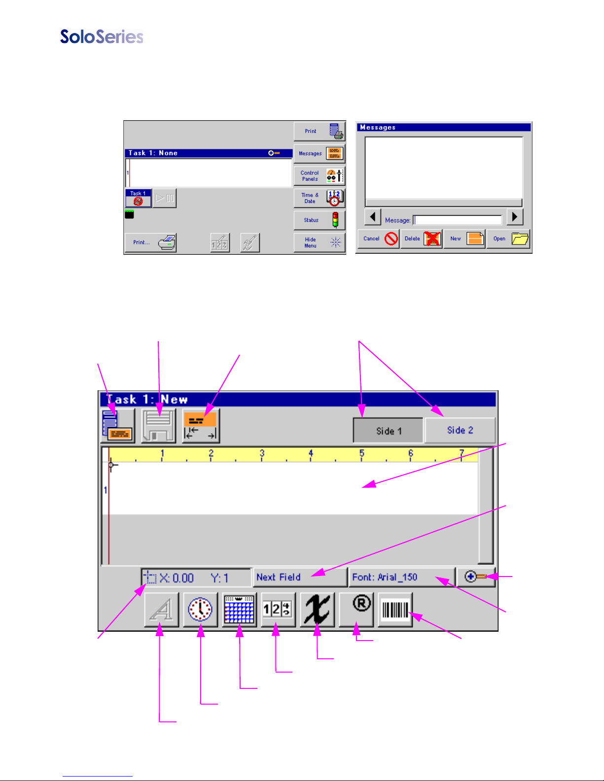
Step 8: Create a Message
From the home screen, select the Messages button and then the New button to enter the
message editor.
Create and save the message, and then exit the message editor.
File Menu
Quick Save
Product Setup
Product Side
Message
Display
Area
Field
Selection
Zoom
Font
Selection
Field
Coordinates
Alpha / Numeric
5780-329 Operations Manual Rev J Page 11
Date Code
Time Code
Variable Field
Count Code
Logo
Barcode
Page 17
Thermal Jet
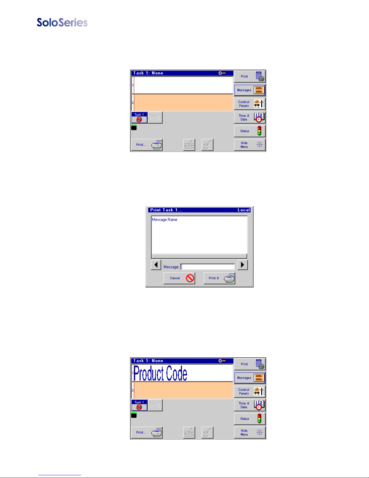
Step 9: Print a Message
From the home screen, push the Print button.
Select the desired message to print, and push the Print It button.
The message will print on the next photocell trigger.
5780-329 Operations Manual Rev J Page 12
Page 18

Thermal Jet Section 3: Marksman HHI or GUI Functionality
POWER
SCREEN BRIGHTNESS
BACKSPACE
Section 3: Marksman HHI or GUI Functionality
Keypad or Keyboard
ESC (Escape):
• Closes the current window, a dialog box, or menu.
• Restores the original contents of any input entry box, if Enter has not been pressed.
Arrow Keys:
• Shifts focus between screen controls.
• Moves highlighted fields or the cursor around in the Message Editor.
Tab:
• Shifts focus between screen controls.
• Shifts focus between fields in the Message Editor.
Backspace in Message Editor:
• Normal functionality as QWERTY keyboard.
• Deletes a highlighted field.
Ctrl (Control) in Message Editor:
• Amplifies the movement of the arrow keys.
• Holding the Ctrl key while pressing the Enter key at the end of a text line enables paragraph
functionality.
F4/F8:
The F4/F8 key pulls up the extended characters dialog.
5780-329 Operations Manual Rev J Page 13
Page 19
Thermal Jet
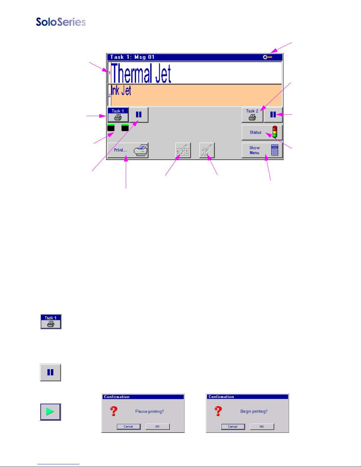
Home Screen
Print Head
Daisy Chain
Identifier
Message
Window
{
Task 1
Select
Button
Task 1, Task 2
Ink Status
Task 1
Print / Pause
Button
Quick Print
Button
Print Counts
Button
Variable Field
Button
Zoom
Button
Task 2
Select
Button
Task 2
Print / Pause
Button
Status
Screen
Access
Button
Show / Hide
Main Menu
Button
{
Play State
Press to
Pause
Pause State
Press to
Print
Message Window:
• Displays the current print message.
• Updated approximately every seven seconds, so it likely will not show each print.
• Long print messages can be viewed by using the F1 and F2 keys to scroll the message left and
right, respectively.
• White or beige bars represent a print head in the daisy chain and are identified by their respective numbering.
• The header displays the task number and file name of the message being printed. If no message is loaded to print, "None" is displayed.
Task Select Button:
• Places focus on the selected task. This allows one to view what is being printed on either task in
the home screen. Additionally, items in the main menu vary from one task to the other.
Task Print / Pause Button:
• Starts and Stops print after an operator response to a confirmation popup dialog box.
• If a message is currently printing, pressing the Pause button will discontinue printing after the
message completes printing.
• If the Play button is pushed, print will resume on the next product detected.
5780-329 Operations Manual Rev J Page 14
Page 20
Thermal Jet
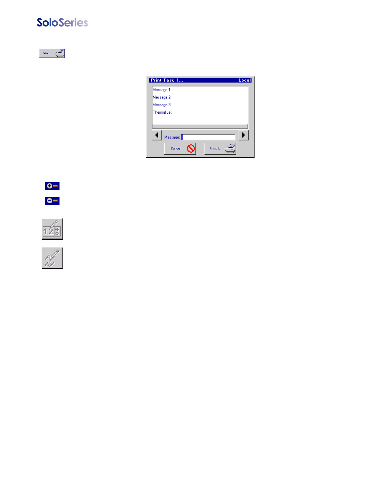
Quick Print Menu Button:
• Allows one to access the Print dialog box directly, even with Restricted User Access enabled.
• Simply select the desired message and press the Print It button. The message will print at the
next photocell trigger.
Zoom:
• Expands the message window to full screen and magnifies the print message so that fine details
may be seen.
• F1, F2, F5 and F6 keys, or the Arrow keys, scroll the message left, right, up and down.
• Press the Zoom button or the ESC key to zoom back out.
Counter:
• Count codes are allowed, but one must select the "Print" button to adjust the count.
Variable Field:
• Variable information fields are allowed, but one must select the "Print" button to change the
information being printed.
5780-329 Operations Manual Rev J Page 15
Page 21

Thermal Jet
Main Menu
Main Menu Collapsed
Print Menu
Main Menu Expanded
Print Menu Button
Cancels print immediately
after a confirmation popup
dialog box
Closes this menu
immediately
NOTE: The Variable Field button
is not available. In order to
update a variable field, reselect
the message to Print.
Fires all jets for a short
period of time on the
selected print head
Messages Dialog & the Message Editor
Messages Dialog
Returns to
Home Screen
Deletes Selected Message
Returns to Home
Screen
Message List
Selected
Message
Opens Selected
Message in the
Editor
Starts a new message in the Editor
5780-329 Operations Manual Rev J Page 16
Page 22
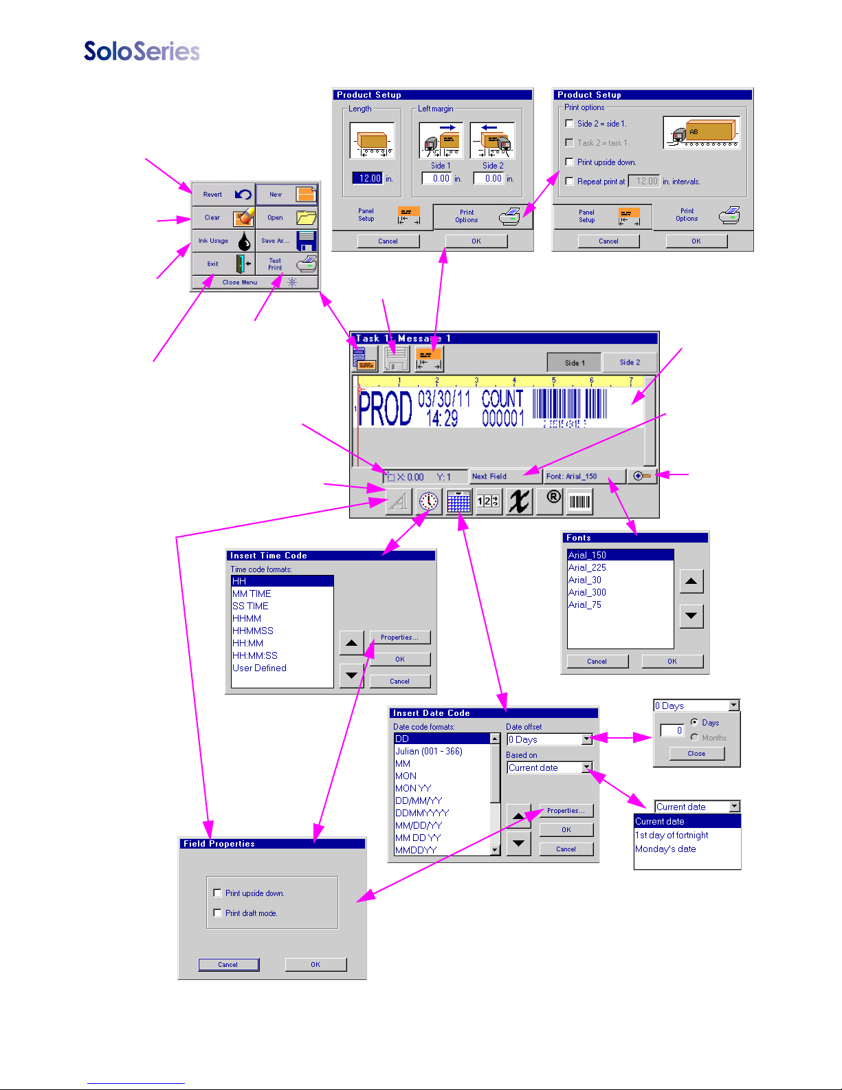
Reverts
message
to the last
saved
Clears
contents of
message
editor
Thermal Jet
Message Editor
File Menu
Calculates
estimated ink
usage for the
contents of
the editor
Exits the
editor to the
Home
screen
Prints the contents
of this editor on the
next photocell
trigger
Field or cursor
coordinates
Opens Field Properties
dialog box for text fields
Quick save
of current
message
Message
display
area
Moves from
field to field in
the display area
Zoom
5780-329 Operations Manual Rev J Page 17
Page 23
Thermal Jet
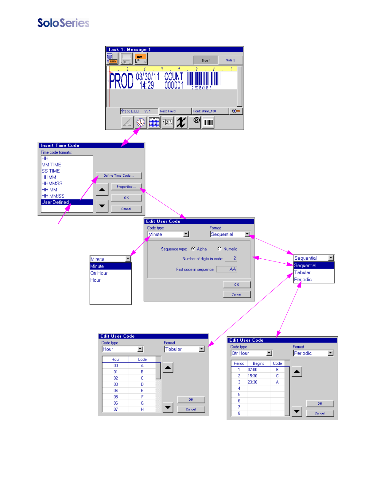
Message Editor continued: User Defined Time Codes
When User Defined selected,
Define Time Code button
appears
Sequential format: minute code shown.
Minute 00 = AA, 01 = AB, 02 = AC, etc.
Tabular format: codes printed taken from
table. Use default codes (default Hour codes
shown) or edit table to suit your requirements.
5780-329 Operations Manual Rev J Page 18
Periodic format: example above illustrates a
shift code implemented by using a periodic
quarter hour code. ’A’ prints from 23:30 06:59, ’B’ from 07:00 - 15:29, and ’C’ from
15:30 - 23:29.
Page 24
Thermal Jet
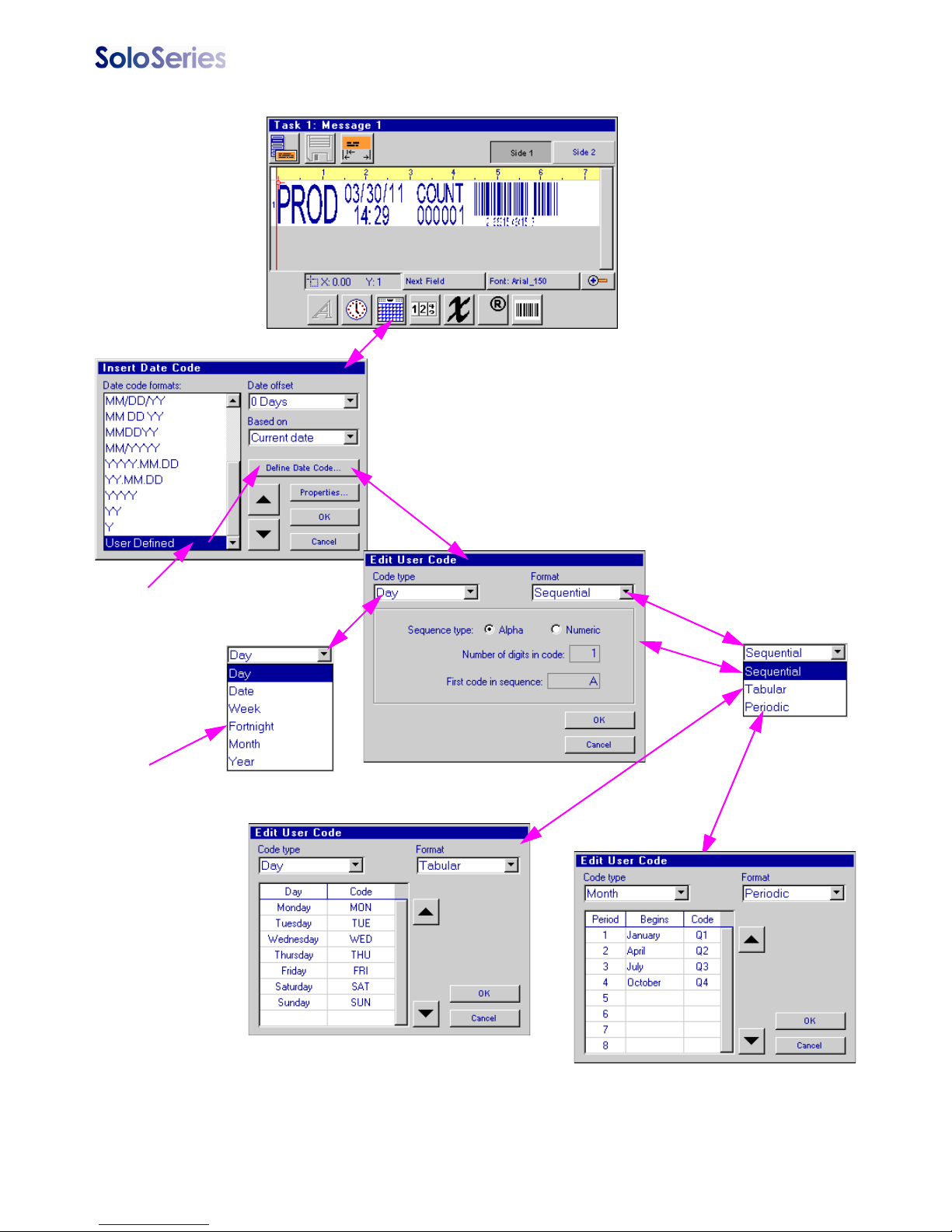
Message Editor continued: User Defined Date Codes
When User Defined selected,
Define Date Code button
appears
The Fortnight code
type is available for
the Tab ular format
only
Sequential format: in example above
Sunday = ’A’, Monday = B, etc
Tabular format: codes printed taken from
table. Use default codes (default Day codes
shown) or edit table to suit your requirements
5780-329 Operations Manual Rev J Page 19
Periodic format: example above illustrates a
quarter year code implemented by using a
periodic month code. ’Q1’ prints from Jan 1 Mar 31, ’Q2’ from Apr 1 - Jun 30, etc.
Page 25
Thermal Jet
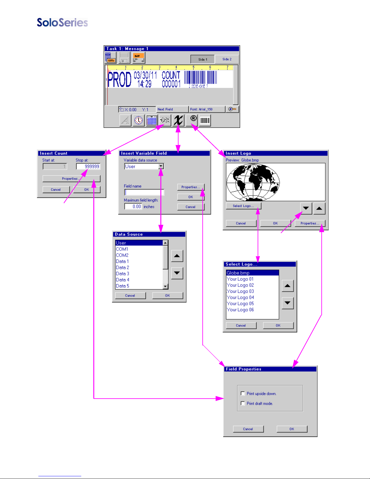
Message Editor continued: Product Counts, Variable Fields, Logos
Maximum 9-digit
count
Scroll through logo
images or select
from list
Variable Field Data Source
User: Print data entered when print
message containing the variable field
is selected to print.
COM1, COM2: Data is received
though COM1 or COM 2 serial port.
Data must be received before the
message is selected to print.
Data 1 - 10: Data is retrieved from
corresponding system variable. User
has the option to change the data
when the message is selected to
print.
5780-329 Operations Manual Rev J Page 20
Page 26
Thermal Jet
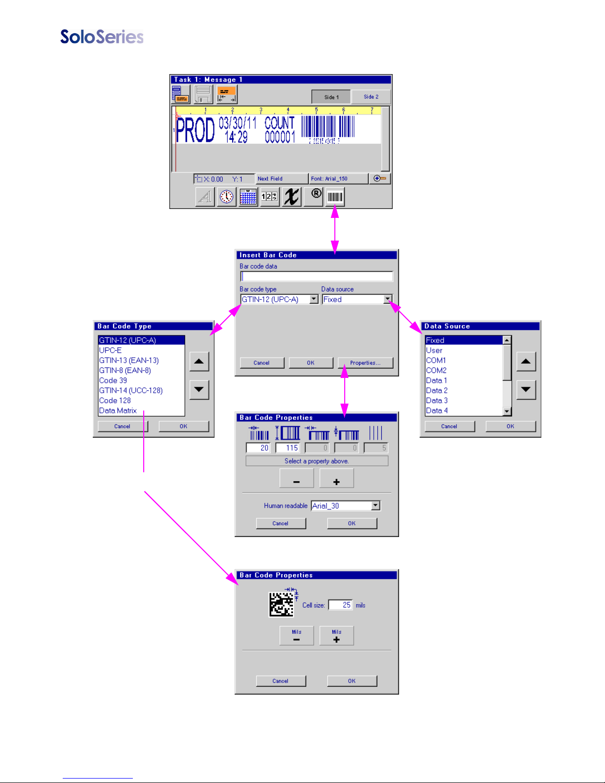
Message Editor continued: Bar Codes
Properties dialog for
Data Matrix code
Bar Code Data Source
Fixed: Data entered when the
bar code is created.
User: Data entered when print
message containing bar code
is selected to print. Dummy
data entered when the bar
code is created acts as a place
holder.
COM1, COM2: Data is
received though COM1 or
COM 2 serial port. Data must
be received before the message is selected to print.
Dummy data entered when the
bar code is created acts as a
place holder.
Data 1 - 10: Data is retrieved
from corresponding system
variable. Dummy data entered
when the bar code is created
acts as a place holder.
5780-329 Operations Manual Rev J Page 21
Page 27
Thermal Jet
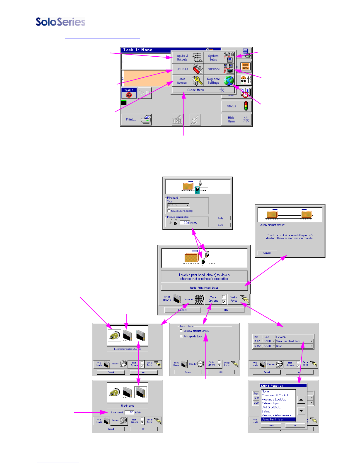
Control Panels Menu
I/O feature not
available on
Marksman HHI
System Utilities
menu for miscellaneous controller
tools and file management
Security Access
System Setup:
NOTE: The Product sesnor
offset is only available when
External product sensor is
selected on the Task Options
tab. In addition, External
encoder or Fixed Speed
must be selected on the
Encoder tab.
Controls print head and
ancillary equipment
configuration
Configures network
connectivity via the
Ethernet port
Language and unit of
measure configuration
Closes this menu
immediately
Set print direction, number
and type of print heads
External Encoder:
Line speed measured by
an externally mounted
encoder and connected
to the last print head in
the daisy chain
Fixed Speed:
Enter the desired
line speed
System
Setup
Screen
Auto Speed
Detect:
Line speed
automatically
detected via SoloSeries photocells
(disables the external product sensor)
Optional externally mounted
photocell connected to the
last print head in the daisy
chain (disables Auto Speed
Detect)
COM port
configuration
options
5780-329 Operations Manual Rev J Page 22
Page 28
Thermal Jet
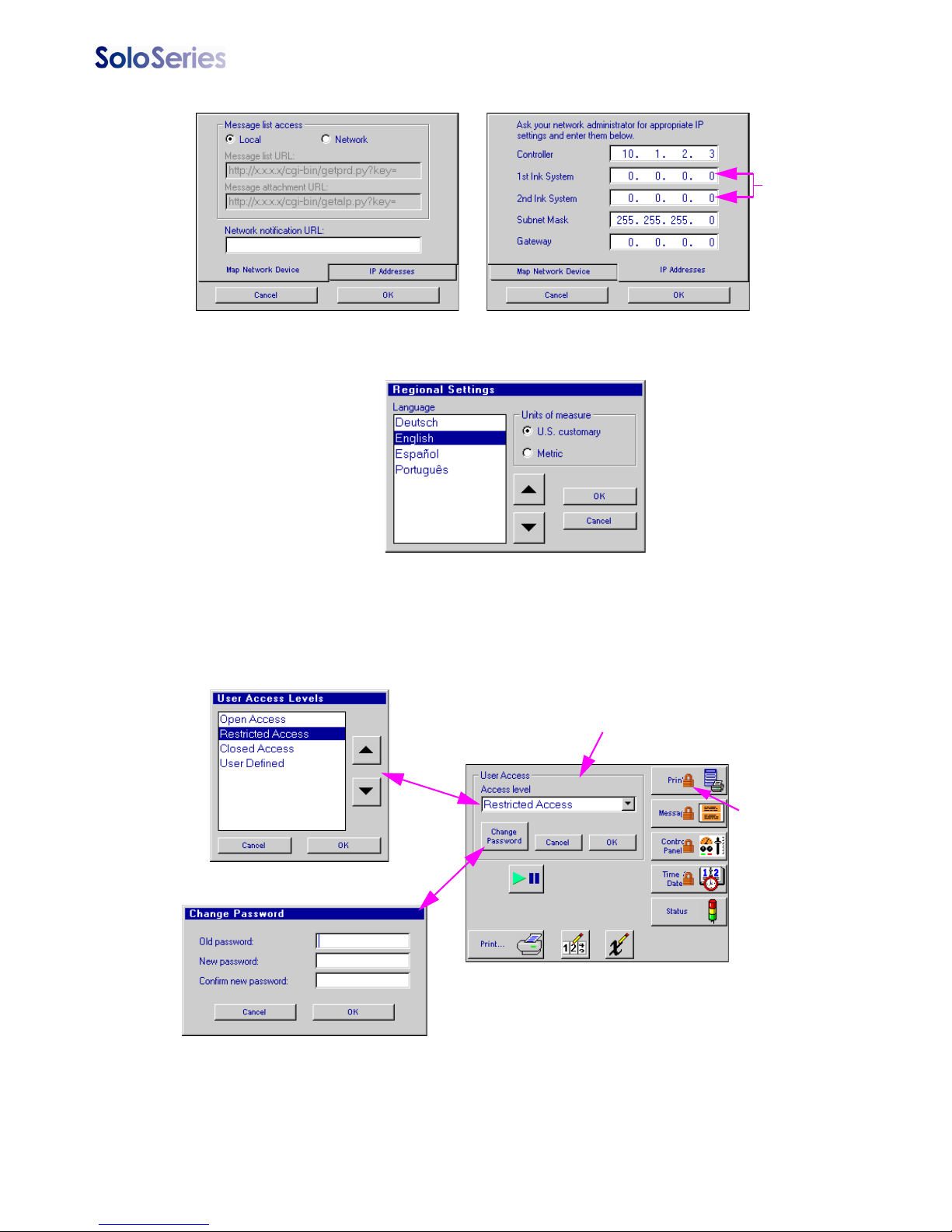
Network:
Regional Settings:
Does not apply
to Thermal Jet
print heads
User Access:
The factory set password is Manager.
Passwords are case sensitive.
Controls within this box set the user
access level. Buttons outside the box
mirror the Home Screen and indicate
which functions are password protected
and which are open.
Padlock symbol
indicates function
is password protected
5780-329 Operations Manual Rev J Page 23
Page 29
Thermal Jet
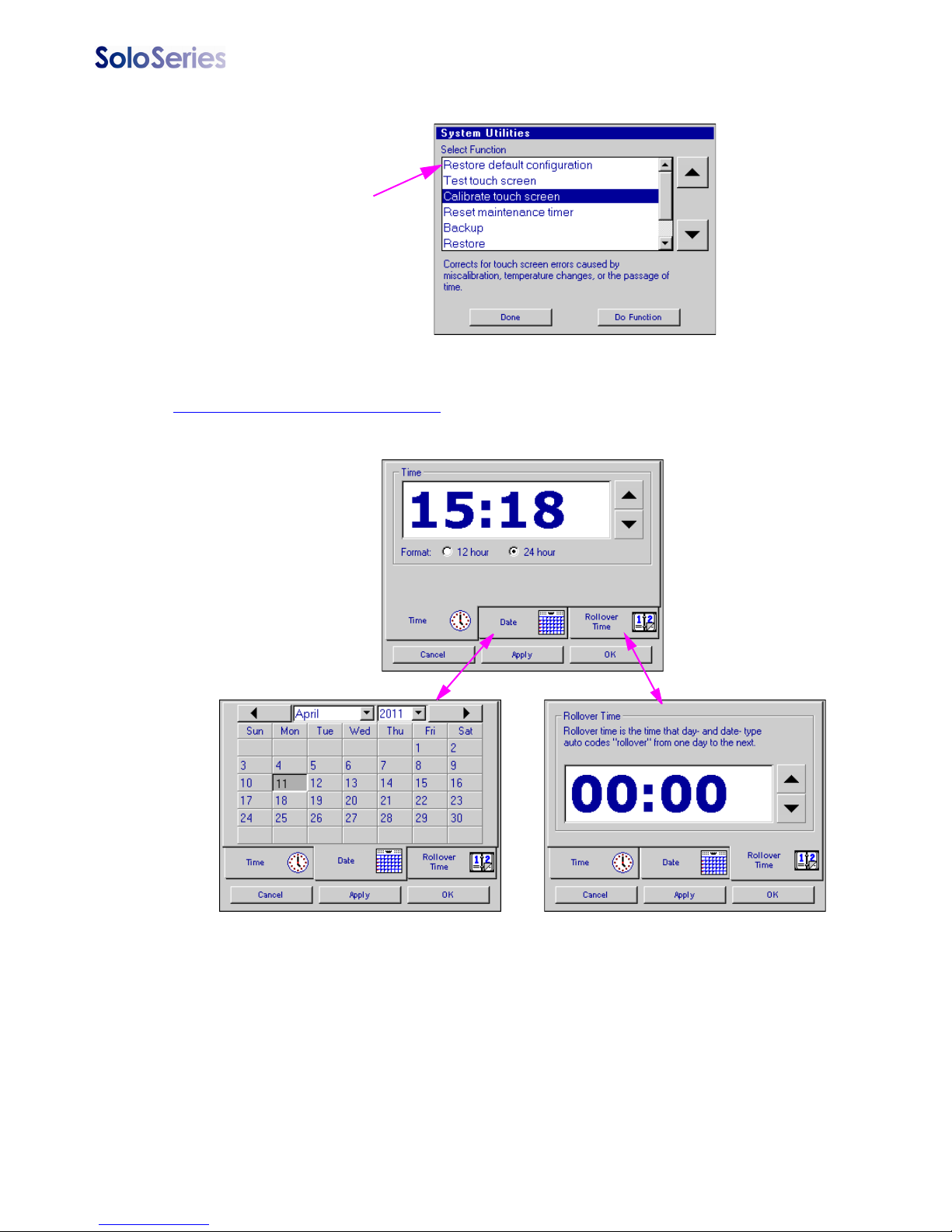
Utilities:
After performing the
Restore default configuration function, the serial
port must be reconfigured
for a serial print head.
Time & Date Setting Screens
5780-329 Operations Manual Rev J Page 24
Page 30
Thermal Jet
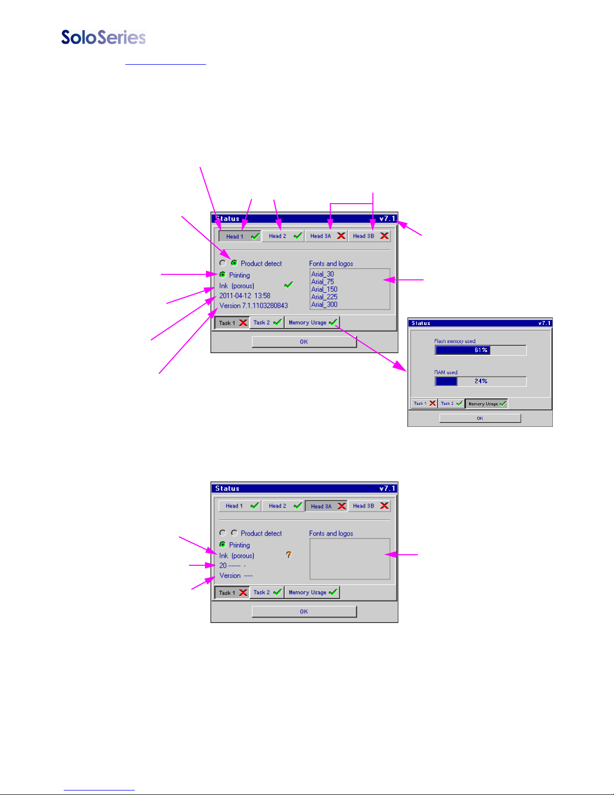
Status Screen
Note: This set of status screens represents three print heads, two SoloSeries45
and a SoloSeries90, setup in a daisy chain. The first two print heads (Head 1 & 2)
are properly connected and detected. The third print head has not been properly
connected to the daisy chain.
One button for each print head/print cartridge
in the daisy chain. Touch/click button to display status for that print head & cartridge.
Head 3 is a SoloSeries90 - one
button for each print cartridge
Controller / GUI
version number
Right hand
photocell (as
seen from front
of print head)
covered and
the left is not
Heads 1 & 2 are
SoloSeries45s
Printing is
enabled
Ink cartridge type
and status - OK
Date (Y-M-D)
and time from
print head
Print head firmware
version number
Ink cartridge
not detected
No date & time
List of fonts and logos
on the print head
Indications that head 3 is improperly
connected or not communicating with
the controller
Font and logo
list is empty
No print head
firmware version
number
5780-329 Operations Manual Rev J Page 25
Page 31
Thermal Jet Section 4: Maintenance & Shutdowns
Section 4: Maintenance & Shutdowns
Daily Maintenance, Ink Cartridge
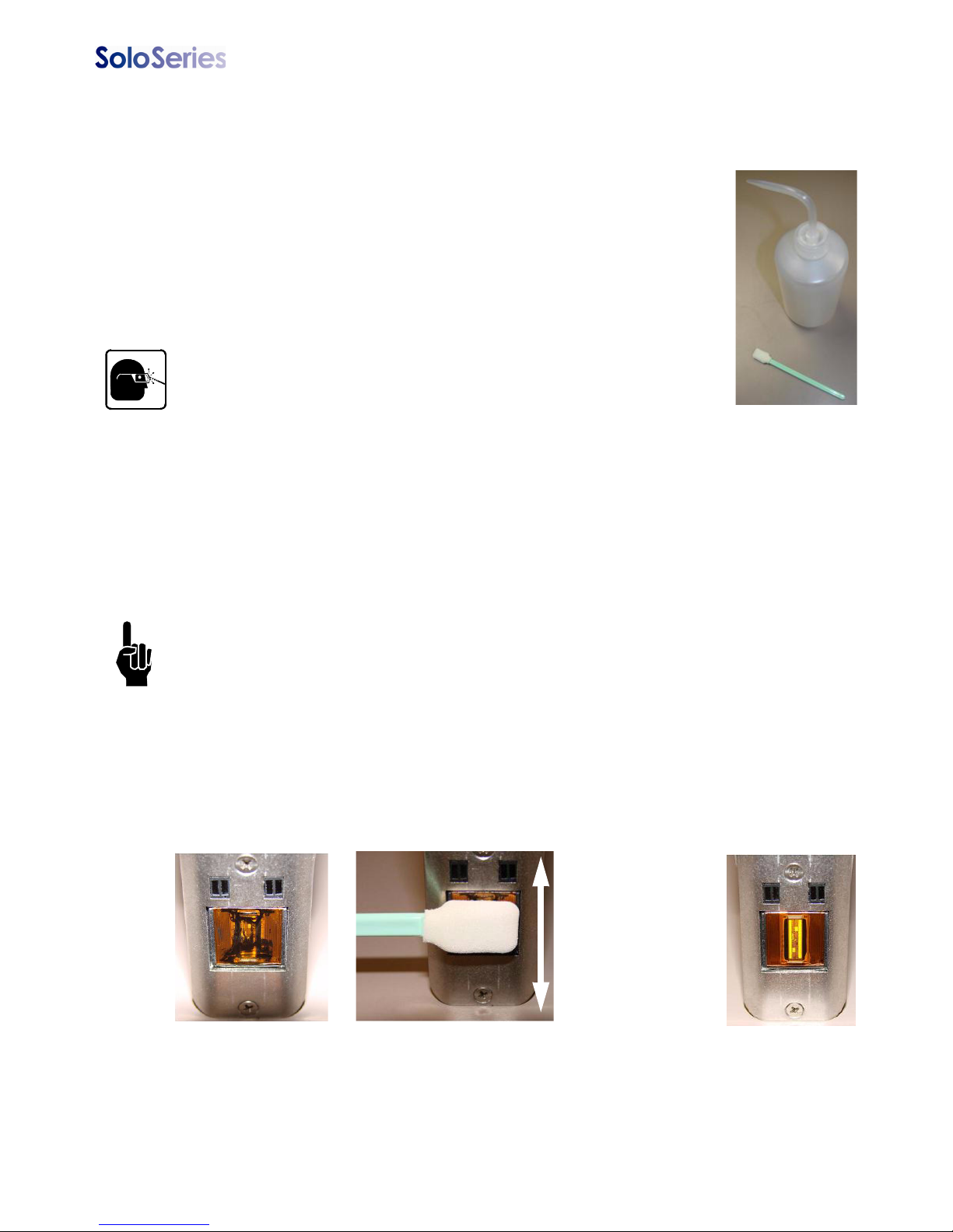
Prior to shift startup, the cartridge orifice array should be cleaned of any
debris or ink build up.
Requirements:
• Deionized or distilled water (DO NOT USE TAP WATER) for POROUS INK
ONLY
• Sponge Swabs (Foxjet p/n: 5760-832)
Procedure:
1. For POROUS INK ONLY cartridges, lightly dampen sponge swab
with deionized water.
2. For NON-POROUS INK ONLY cartridges, hold sponge swab
against orifice array of cartridge. Press and hold the purge button
on the rear of the print head for at least ten seconds. This will fire all channels of the ink
cartridge and dampen the swab with ink. The ink will act as its own solvent for cleaning.
3. Rub up and down across the orifice face with light force several times with one side of
the sponge swab.
4. Turn the swab over and make one final light rub stroke top to bottom.
5. Immediately press and hold the PURGE button on the rear of the print head for 5-10
seconds to reprime the orifices. Because ink will eject during the channel purging, a
piece of paper, cloth, or comparable material can be held in front of the orifice array.
Do NOT hold the ink catch material against the orifice array as print quality will be
degraded.
6. If print quality becomes unsatisfactory during any shift repeat this procedure.
Before cleaning After cleaning
Wipe pen
cartridge face up
and down
several times.
Immediately
press and hold
the purge button
for 5-10 seconds.
5780-329 Operations Manual Rev J Page 26
Page 32
Thermal Jet Section 4: Maintenance & Shutdowns
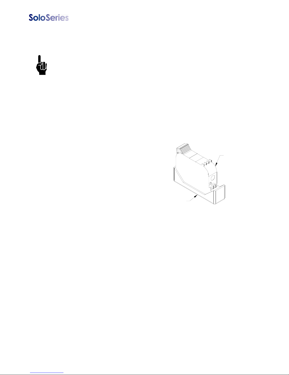
CARTRIDGE BOOT CAP
PEN CARTRIDGE
Weekly to Monthly Maintenance, Print Head
Debris and ink build up on the print head enclosure / cover can be removed using a soft
cloth lightly dampened with deionized water.
Take care NOT to wipe the cartridge orifice array.
Shutdowns Less Than 3 Days
The ink cartridge can remain in the print head uncapped. When restarting the print head,
follow the Daily Maintenance procedure.
Shutdowns More Than 3 Days
For extended shutdowns, follow
the Daily Maintenance procedure,
remove the ink cartridge from the
print head and store in the optional
Cartridge Boot Cap (Foxjet Kit p/n:
5780-208).
5780-329 Operations Manual Rev J Page 27
Page 33

Thermal Jet Section 5: Troubleshooting
Section 5: Troubleshooting
NO PRINT
System Symptom Possible Cause Actions
No print head power /
green LED on rear of print
head
PURGE button on rear of
head does not appear to
work
Print head purges but
won’t print desired message
• Power Supply
•AC Source
• Ink cartridge is damaged
or empty
• Print head Board
• Loose or missing cables
• Controller or PC software
not configured for Serial
Print Head
• Encoder Malfunction
• Product not triggering
photocell.
• Check power supply light indicator.
• Check for AC power source between power supply
input limits.
• Replace with new cartridge and repeat PURGE.
• Replace print head printed circuit board or print head.
• Tighten or install all cables.
• Ensure print heads are configured as serial. See “Section 2: Quick Start”, “Step 6: Cabling, Power, and Serial
Port Setup” on page 7.
• Ensure encoder is installed and plugged into the last
print head in the daisy chain.
• Ensure the product is within 1/4" of the front face of the
print head.
• If an external photocell is installed, then validate the
setting from the Control Panels, System Setup, Task
Options tab.
POOR PRINT QUALITY
System Symptom Possible Cause Actions
Print is foggy or light • Print head is mounted
greater than an 1/8" away
from the substrate
• There are large air currents near the print head
• Adjust the print head according to “Section 2: Quick
Start”, See “Step 4: Adjust SoloSeries Print Head to
Substrate” on page 5.
• Locate print head in an area where there are minimal
currents or provide wind barriers.
Print image is missing
channels or has multiple
fractures
• Pen cartridge face is dirty
• Pen cartridge face is
damaged at the orifice
array
• Pen cartridge is not properly seated in the print
head
• Clean the pen face per “” on page 25.
• Replace damaged pen cartridge with new.
• Remover cartridge and reinsert according to “Section
2: Quick Start”, “Step 5: Insert Pen Cartridge into Print
Head” on page 6.
SoloSeries PRINT HEAD LED FUNCTIONALITY
System Symptom Possible Cause Actions
Red LED on steady • Pen cartridge ink level is
low.
Red LED is flashing slowly • Pen cartridge is out of ink
and significant print degradation is imminent.
• A non-Foxjet cartridge is
installed.
Red LED is flashing fast • Pen cartridge is missing
from print head stall.
• Print head is calibrating a
new cartridge.
• Print head is in thermal
protection mode.
• Ready the next pen cartridge for installation.
• Prepare to install a new pen cartridge.
• Install an original Foxjet cartridge.
• Install or re-install the appropriate pen cartridge.
• Allow the print head up to 30 seconds to calibrate a
new pen cartridge.
• Pen cartridge is out of ink and the print head is self-protecting against excessive heating. Replace the appropriate pen cartridge.
5780-329 Operations Manual Rev J Page 28
Page 34
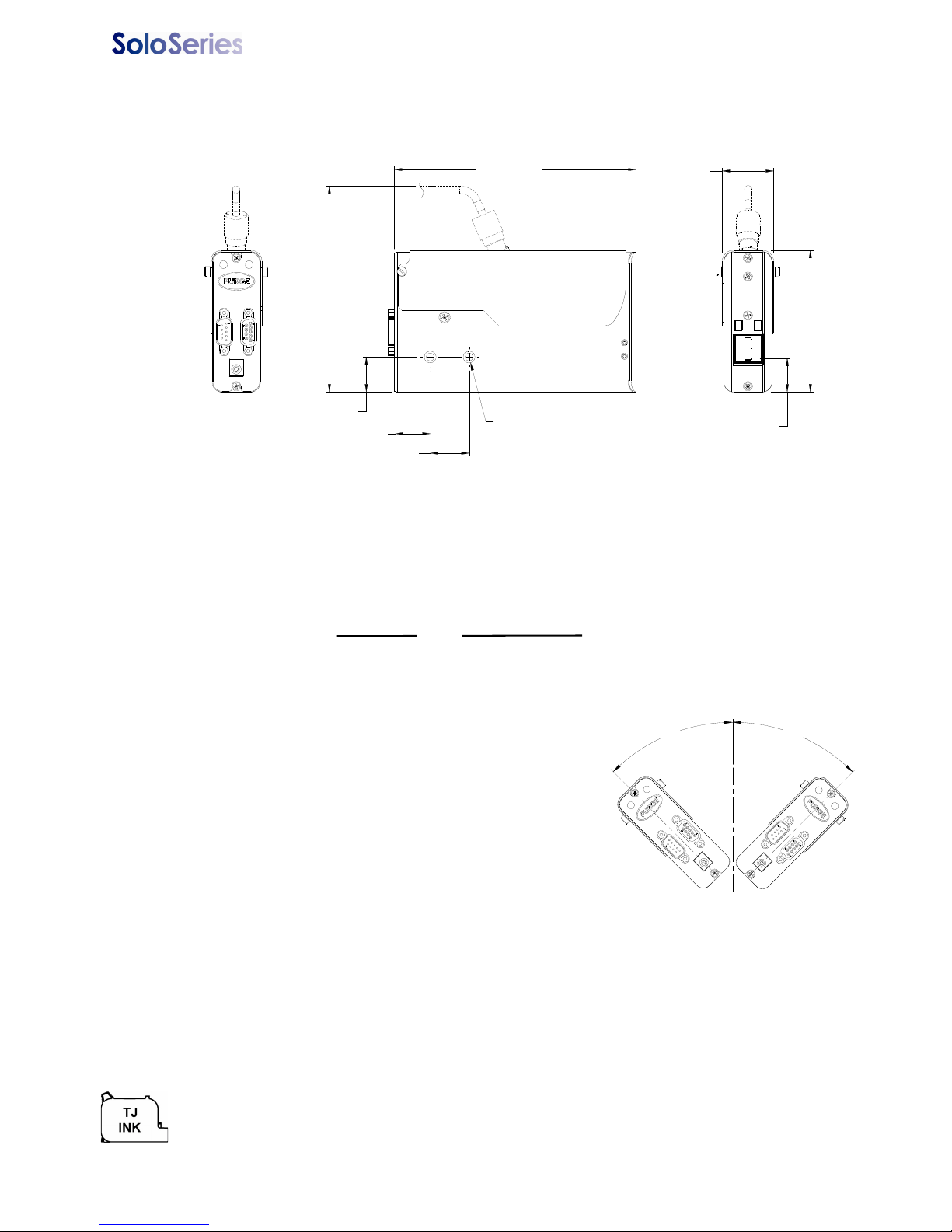
Thermal Jet Appendix A: Specifications
45°
45°
PRINT HEAD TILT
0.87 in
[22.1 mm]
LOWEST
CHANNEL
3.65 in
[92.6 mm]
0.90 in [22.9 mm]
0.90 in [22.8 mm]
1.00 in [25.4 mm]
2X M6 X 1.0 X x .16 in [4.06 mm]
PROVIDED FOR PRINT
HEAD MOUNTING
(BULK INK ONLY)
5.30 in
[134.6 mm]
1.32 in
[33.6 mm]
6.23 in
[158.2 mm]
Appendix A: Specifications
SoloSeries45:
k
g
(
.
6
i
z
e
o
d
o
w
e
r
9
0
-
2
6
m
f
p
0
0
:
3
0
n
e
:
:
G
a
p
a
t
t
e
n
:
t
i
c
a
l
f
r
t
i
c
a
l
f
r
n
t
F
i
e
p
s
o
f
h
m
a
y
s
p
e
r
s
c
r
e
a
k
B
5
6
t
o
r
l
e
s
s
t
a
y
i
n
e
d
t
a
l
l
i
n
.
7
5
:
1
l
e
s
n
g
t
e
i
P
i
g
m
h
o
e
S
e
a
r
t
L
d
u
c
r
o
)
l
u
m
d
A
u
p
p
l
y
s
A
V
C
0
,
3
0
0
p
i
0
d
P
o
r
i
n
.
1
.
2
5
F
r
i
o
n
:
r
s
t
a
n
o
r
B
u
l
k
o
l
d
s
:
r
i
n
t
p
e
t
a
v
e
a
l
i
n
e
i
n
c
e
s
.
t
o
r
s
e
c
.
F
a
g
e
f
o
l
l
e
d
s
:
f
o
n
t
.
0
5
/
1
9
o
t
s
5
0
d
p
e
r
a
m
e
n
t
e
d
,
l
o
S
e
r
i
e
k
v
e
I
n
l
f
e
t
y
t
s
a
W
E
E
1
P
P
P
T
R
M
P
P
+
+
N
M
E
n
t
F
T
f
s
F
i
B
3
E
A
I
I
S
i
e
o
n
n
n
n
l
b
t
:
e
i
g
h
l
o
s
u
n
c
l
e
c
t
r
i
c
V
D
C
5
w
e
r
S
o
p
r
i
n
t
S
t
R
e
r
i
n
r
o
w
D
h
m
e
c
o
m
u
a
x
i
m
t
H
e
r
i
n
i
n
t
H
e
r
-
4
5
°
f
/
-
9
0
°
f
/
e
u
m
b
u
a
x
i
m
r
a
c
h
p
r
u
m
b
e
r
r
s
p
e
t
o
S
i
l
e
t
y
-
w
e
n
a
n
d
n
t
r
s
.
e
c
t
o
f
a
c
i
v
e
7
2
.
/
1
a
p
i
t
m
p
i
)
0
0
d
v
i
r
o
n
n
b
i
e
n
m
k
y
p
T
a
k
r
C
t
e
r
o
l
o
S
u
s
a
g
k
s
1
.
3
:
A
n
r
e
a
l
:
f
r
o
m
p
u
p
p
l
y
:
2
e
e
d
:
l
u
t
i
o
s
o
i
a
s
t
n
c
d
e
n
d
e
p
:
m
G
a
i
O
r
a
d
a
d
i
l
T
t
v
o
e
m
r
o
m
v
e
r
r
i
r
o
f
P
n
e
m
5
l
i
i
n
t
l
i
n
e
l
d
o
f
f
i
e
e
f
i
e
l
d
d
e
:
r
a
g
e
n
2
s
e
v
o
f
i
l
o
g
c
t
o
r
F
a
i
n
s
y
t
o
r
,
0
m
m
o
)
f
(
i
l
o
g
.
e
n
t
:
m
p
e
r
a
t
e
r
i
t
o
,
:
D
y
e
T
i
e
d
:
g
m
e
s
’
S
n
d
p
e
a
e
z
m
t
r
2
s
r
7
(
n
a
,
u
)
n
c
c
t
r
t
t
t
y
5
n
i
5
.
t
t
n
e
d
1
.
u
o
)
t
a
l
a
r
a
r
t
g
i
d
c
h
e
h
h
e
h
a
1
2
,
1
/
i
n
o
1
b
a
e
n
y
S
f
u
n
e
A
m
5
s
N
o
.
0
8
.
1
5
s
t
o
i
d
g
t
r
d
g
e
r
i
e
a
t
a
r
a
c
n
u
m
a
d
a
n
2
5
t
o
f
5
0
,
2
5
.
4
2
/
1
4
°
0
s
e
h
g
i
n
e
s
t
e
m
o
c
t
i
m
a
n
t
r
m
d
u
h
p
r
i
n
t
0
/
6
0
H
n
t
i
p
u
a
p
a
r
n
i
c
o
s
I
n
k
m
m
2
.
5
m
(
6
.
3
h
o
r
i
z
o
n
r
d
p
r
i
t
n
k
p
r
i
n
c
a
r
i
n
t
3
5
a
s
t
s
a
a
s
e
r
p
r
i
n
p
e
r
g
e
l
a
s
c
c
u
p
s
o
l
3
0
,
i
a
,
1
.
0
m
m
a
x
l
l
F
r
e
:
5
0
°
v
e
n
S
o
l
e
e
h
a
s
b
c
t
i
o
e
t
e
i
l
l
n
o
t
b
i
n
o
t
5
,
d
o
(
i
n
o
m
d
I
r
l
e
r
e
s
i
l
e
n
A
t
t
u
o
s
D
,
w
s
S
t
a
i
n
l
l
s
S
t
e
e
s
u
p
p
l
y
o
w
e
r
.
(
p
e
a
n
-
n
i
n
i
t
r
a
r
x
o
r
o
u
s
P
(
2
.
0
m
(
3
.
8
m
t
d
o
i
g
h
p
I
n
k
m
)
m
)
.
w
n
)
e
t
.
l
e
o
0
2
d
e
w
p
l
d
r
u
r
0
,
4
g
s
v
o
i
n
s
;
a
c
-
o
f
i
p
l
t
.
s
(
6
7
0
°
e
s
i
g
n
i
d
e
i
t
h
r
l
e
0
.
1
i
n
7
c
o
l
o
p
C
)
;
d
t
o
e
s
i
n
k
F
n
o
n
-
m
,
0
.
6
.
3
5
.
2
5
i
n
m
m
,
/
2
.
5
m
n
s
u
i
e
r
a
t
r
k
o
w
v
e
l
l
e
o
x
j
e
t
4
i
d
e
m
w
n
g
h
u
m
F
o
i
t
h
w
n
i
t
o
r
o
m
i
n
k
c
a
r
0
x
(
1
0
a
1
i
d
i
t
y
:
i
n
k
x
j
e
t
t
o
e
i
n
g
r
i
d
g
e
s
.
t
m
/
i
n
/
2
.
9
8
0
0
%
-
r
i
d
g
c
a
r
t
u
r
e
c
n
s
5
t
9
m
a
7
H
%
R
e
h
T
e
s
.
e
p
l
e
t
o
m
n
a
r
t
e
b
r
e
6
k
h
e
2
2
5
m
.
7
F
(
4
p
e
r
e
,
w
n
a
l
n
y
g
i
v
e
f
i
e
p
r
i
n
t
h
2
m
5
d
i
a
r
o
f
c
i
l
a
b
v
a
e
m
u
s
s
e
c
t
7
d
3
,
a
n
)
.
3
)
;
m
°
C
t
o
0
r
i
c
a
r
t
a
n
d
d
p
r
o
h
i
c
h
u
s
e
d
f
e
a
B
m
1
5780-329 Operations Manual Rev J Page 29
Page 35
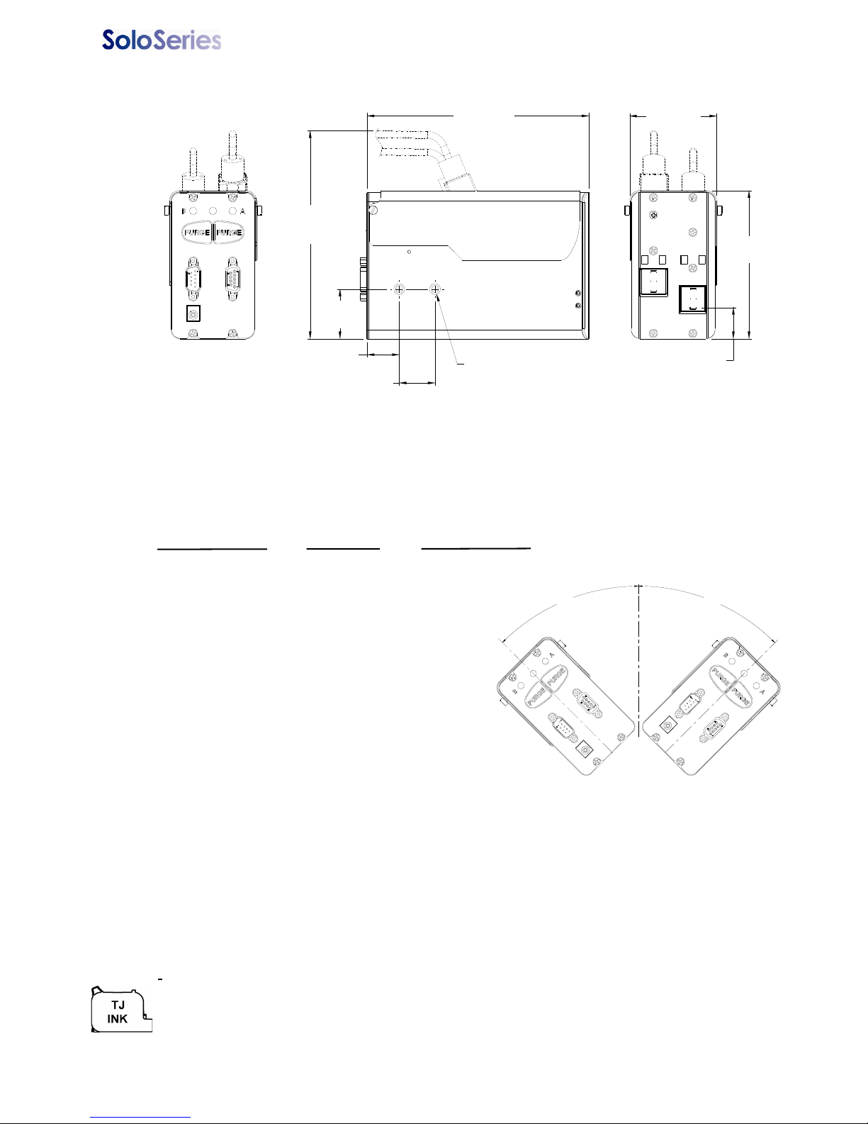
PRINT HEAD TILT
45°
45°
0.87 in [22.1 mm]
LOWEST
CHANNEL
4.13 in
[104.9 mm]
6.20 in
[157.4 mm]
5.81 in
[147.5 mm]
(BULK INK ONLY)
2.43 in
[61.8 mm]
1.00 in
[25.4 mm]
0.90 in
[22.8 mm]
1.38 in
[35.2 mm]
2X M6 X 1.0 X.16 in [4.06 mm]
PROVIDED FOR PRINT
HEAD MOUNTING
SoloSeries90:
e
W
E
n
E
l
e
1
5
P
o
w
P
r
i
P
r
i
T
h
r
R
e
M
a
m
m
P
r
i
P
r
i
/
-
+
/
+
-
N
u
a
M
f
o
r
m
a
o
f
f
t
e
r
s
F
i
l
e
T
w
2
5
6
F
i
v
i
n
/
B
i
t
m
a
t
3
E
n
A
m
O
p
n
k
I
I
n
k
e
r
S
d
a
n
Thermal Jet Appendix A: Specifications
)
1
.
0
k
.
1
l
b
i
g
h
t
:
l
o
s
u
c
c
t
r
i
c
V
D
C
e
r
S
t
p
S
n
t
R
e
n
o
w
D
o
m
m
c
u
x
i
m
s
2
e
:
A
n
r
:
a
l
p
o
m
f
r
p
p
l
y
:
u
e
d
:
2
e
o
l
u
t
i
o
s
a
t
n
c
i
s
n
d
e
d
e
G
a
p
m
g
(
e
a
m
n
i
l
n
u
i
z
o
d
e
o
w
0
-
2
9
f
p
0
0
:
3
n
:
e
a
G
:
m
e
d
A
p
l
y
t
s
r
6
0
m
0
0
p
:
o
u
p
A
C
,
5
V
3
0
0
d
,
p
i
d
P
o
r
o
.
1
i
n
(
.
2
5
i
n
d
u
p
r
i
n
t
h
p
u
2
e
z
0
/
6
0
H
i
s
(
u
c
o
n
t
i
n
I
n
k
)
.
5
m
m
6
.
3
m
m
s
S
t
a
i
n
l
e
a
d
,
m
1
.
5
A
o
u
s
o
N
8
.
0
5
)
.
1
l
s
S
t
e
p
p
l
y
w
e
r
(
p
e
a
n
-
i
n
i
n
r
x
.
r
o
u
s
P
o
.
0
m
(
2
.
8
(
3
p
o
k
I
n
m
)
)
s
u
)
n
n
n
m
x
y
i
e
e
v
e
t
t
.
n
m
F
n
g
o
g
r
i
d
c
a
r
t
t
g
c
t
r
r
E
t
b
l
l
i
n
5
7
i
1
(
t
t
e
e
m
i
f
e
a
r
t
r
i
d
1
i
d
g
e
,
r
i
a
c
h
p
;
n
f
i
e
l
d
s
c
e
r
o
f
a
a
r
e
a
v
s
t
a
l
l
e
d
2
,
1
5
0
,
4
n
/
2
5
.
.
0
i
n
/
°
F
o
1
0
4
b
a
s
e
h
r
e
n
g
i
n
e
e
,
h
w
i
c
h
d
i
w
u
s
e
o
n
t
a
l
i
r
m
z
r
d
p
r
i
n
a
k
p
r
i
n
n
r
i
n
t
c
a
p
p
o
i
n
t
n
e
r
p
r
i
c
t
h
e
n
u
t
e
r
s
t
a
p
c
t
o
r
y
a
l
3
0
,
i
a
,
1
.
0
m
a
x
l
m
a
l
:
5
0
°
r
e
R
H
%
o
l
v
e
r
S
s
b
e
e
n
a
y
s
t
o
S
n
l
n
c
t
i
o
n
a
:
H
o
n
s
t
a
n
r
B
u
l
k
r
:
d
s
t
p
e
i
n
g
i
v
n
y
h
a
2
-
c
e
s
a
s
s
.
c
t
o
r
s
e
o
r
s
.
c
t
t
s
:
o
n
.
0
5
1
9
o
t
s
0
d
e
r
a
p
-
0
%
d
,
n
t
e
r
i
e
s
e
S
c
e
D
t
e
o
t
b
e
r
d
I
r
e
r
a
s
s
F
A
t
t
u
8
0
o
h
t
i
f
u
a
t
t
i
r
t
t
5
4
0
9
b
i
m
h
e
t
h
e
l
p
S
n
k
B
f
2
1
a
0
0
i
r
i
e
b
r
a
y
T
a
C
i
e
s
p
r
O
H
e
a
d
i
l
T
H
e
a
d
v
°
°
e
u
a
d
s
r
e
t
o
t
y
a
c
.
7
p
d
o
n
t
p
r
t
’
S
o
e
f
r
o
m
v
e
f
r
o
m
f
P
r
i
r
o
5
l
i
n
m
t
h
e
p
r
i
n
e
a
t
l
v
e
r
l
i
n
p
e
l
d
d
e
f
i
e
e
:
r
a
g
e
n
-
u
n
i
d
s
e
v
m
u
s
e
y
i
n
s
t
o
r
m
,
0
m
o
)
f
(
l
o
g
.
p
i
)
n
t
:
m
e
e
r
a
t
o
p
u
m
n
g
H
y
e
e
:
D
g
e
T
:
r
i
d
e
L
a
m
r
t
u
c
t
s
a
f
e
o
i
e
n
t
:
c
a
l
f
o
r
t
i
a
l
f
o
r
t
i
c
F
i
e
l
n
t
o
f
p
e
a
e
2
l
,
r
s
,
a
t
a
d
t
3
5
a
s
c
r
e
a
i
n
e
a
s
e
c
r
6
k
B
5
l
e
s
e
t
i
p
l
e
d
f
t
a
l
i
n
/
.
7
5
:
3
0
i
l
e
s
t
e
m
t
i
n
g
t
y
:
1
i
d
i
g
m
e
P
i
o
l
S
o
h
e
k
n
v
e
l
I
,
i
t
l
y
w
l
n
h
s
t
r
a
i
.
t
d
o
w
e
l
0
t
o
t
a
e
n
t
l
i
n
e
r
u
m
b
-
h
a
r
a
c
r
t
h
a
n
s
l
a
r
g
e
.
F
i
l
d
l
t
h
o
f
i
n
o
7
c
o
r
w
o
m
n
a
r
t
r
i
d
e
/
2
l
u
k
w
i
t
o
g
e
m
f
s
e
c
t
o
7
2
m
m
,
.
5
i
t
r
i
s
4
s
w
i
d
e
n
o
x
F
j
e
h
o
e
n
n
g
t
.
t
a
r
f
o
u
p
3
0
)
;
t
o
t
r
i
d
i
g
s
i
n
j
e
x
n
n
1
2
y
(
0
.
1
0
,
7
6
3
2
C
°
)
4
0
e
s
g
e
d
t
o
n
v
e
l
k
l
e
t
i
n
k
c
f
o
i
l
a
b
l
e
o
c
f
o
2
m
2
p
d
p
t
h
c
n
t
s
n
d
5
,
a
.
m
)
m
5
.
4
m
C
(
1
0
°
a
r
4
5
c
d
e
a
n
d
s
r
i
d
o
v
e
o
n
o
-
F
n
s
t
o
r
a
i
l
e
o
g
o
e
g
s
.
r
.
2
5
i
n
0
m
a
x
(
i
n
k
c
a
r
t
e
c
o
u
r
s
e
6
.
3
5
/
0
9
i
n
1
r
i
d
g
e
s
.
t
t
e
l
e
p
m
5
m
,
0
.
m
2
/
T
i
n
.
7
9
m
l
o
-
o
e
S
h
u
s
a
g
e
k
5780-329 Operations Manual Rev J Page 30
Page 36
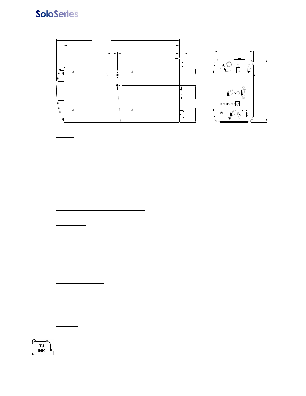
Thermal Jet Appendix A: Specifications
11.00 in
[279.4 mm]
1.00 in
[25.4 mm]
5.89 in
[149.7 mm]
1.00 in
[25.4 mm]
3.75 in
[95.3 mm]
6.00 in
[152.4 mm]
3.50 in
[88.9 mm]
.44 in
[11.3 mm]
11.68 in
[296.6 mm]
3X M6 X 1.0 X x.20 in [5.1 mm]
PROVIDED FOR INK SUPPY MOUNTING
SoloSeries IS:
Weight
4.2 lbs (1.9 kg) without ink cartridge
5.4 lbs (2.5 kg) with ink cartridge
Enclosure
Powder-coat painted steel
Mounting
Modular brackets included
Electrical
15 VDC from power supply to print head
Power Supply: 90-260 VAC, 50/60 Hz, 1.5 A max. (per power supply)
Normal Operating Pressure Range
4 psi to 5 psi
Cable Ports
(1) 15 VDC power supply jack
(1) Communications port
Plumbing Port
(1) Pressurized ink outlet to print heads
Environment
Ambient operating temperature: 50°F to 104°F (10°C to 40°C)
Operating Humidity: 10% - 80% RH
Tubing Limitations
Maximum horizontal tube length = 10 ft (3 m)
Maximum vertical tube length = 3 ft (1 m)
Print Head Limitations
Up to 8 print head cartridge stalls (eg: 8 SoloSeries45s; 4 SoloSeries90s; 4 SoloSeries45s
with 2 SoloSeries90s, etc.)
Ink Type
Dye base
Ink Cartridge: The SoloSeries has been engineered and designed to work with Foxjet ink cartridges. The SoloSeries’ Smart Level Ink Detection System, which provides ink level monitoring to ensure complete ink usage
and product safety, will not be functional if used with non-Foxjet ink cartridges.
5780-329 Operations Manual Rev J Page 31
Page 37
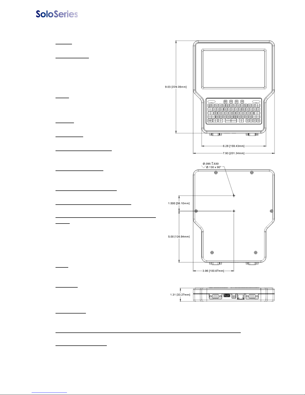
Thermal Jet Appendix A: Specifications
Marksman HHI:
Weight
1.8 lbs (0.82 kg)
User Interface
Type: Graphical User Interface
Keyboard: 70-key, QWERTY style, elastomeric
keyboard
800 X 480 color LCD with touch screen, 7.0"
(177.8 mm) diagonal
Fonts
Arial 30, 75, 150, 225, and 300 (0.1in / 2.5 mm,
0.25 in / 6.3 mm, 0.5 in / 12.7 mm, 0.75 in /
19.05 mm, and 1 in / 25.4mm).
Storage
128 MB flash memory
Print Speed
Up to 200 fpm
Maximum Lines of Print
5 per print cartridge through any given vertical
line.
Print Fields per Line
At least 3 52-character fields per print line; more
when fields have less than 52 characters.
Maximum Product Length
108 inches (2743 mm)
Maximum Repeat Print Distance
108 inches (2743 mm)
Maximum Number of Print Heads Per Controller
Up to 8 print cartridges per COM port in any
combination (eg: 4 SoloSeries45s and 2
SoloSeries90s; 8 SoloSeries45s; 4
SoloSeries90s)
2 COM ports allow for a total of16 print cartridges per controller
Ports
(2) RS-232 ports, (1) 10/100Base-T Ethernet
port, (1) USB port
Electrical
15 VDC from power supply to controller
Power Supply: 90-260 VAC, 50/60 Hz, 1.5A
max. (per power supply)
Environment
Ambient operating temperature: 40°F to 104°F (5°C to 40°C)
Operating humidity: 10% - 90%, non-condensing
Maximum Distance Between Controller and Farthest Print Head in Daisy Chain
100 feet (30.5 m)
Bar Codes Supported
GTIN-12 (UPC-A), EPC-E, GTIN-13 (EAN-13), GTIN-8 (EAN-8), Code 39, GTIN-14 (UCC-128),
Code 128, Data Matrix
5780-329 Operations Manual Rev J Page 32
Page 38

Thermal Jet Appendix B: Theory of Operation
Appendix B: Theory of Operation
SoloSeries Series Print Heads
TIJ Technology
The SoloSeries print head uses Thermal Ink Jet (TIJ) technology as implemented on the
®
hp
45A cartridge. TIJ technology works by rapidly heating the ink. As the ink heats it
expands and is ejected from the print cartridge orifices. Because the individual orifices are
very small, many more can be compacted in the same amount of space as conventional
print technologies. With more orifices per vertical inch / millimeter, a much higher resolution
image can be produced.
SoloSeries Inkjet Similarities and Differences
A SoloSeries print head can operate stand-alone or in concert with other SoloSeries print
heads connected one to another in a daisy chain configuration. Up to eight SoloSeries45 or
four SoloSeries90 print heads can be daisy chained. SoloSeries print heads can be controlled by the Marksman HHI controller, from a PC or labtop using the included GUI software interface program, or by a user developed application.
SoloSeries Series print heads can print up to five lines of print, using any combination of
the various print field types supported, including fixed text, date/time codes, product
counts, variable fields, logos, and a variety of bar codes, including Data Matrix 2-D codes.
Unlike other Foxjet inkjet technologies, the SoloSeries print heads store and process the
currently printing message internally. This allows the print heads to be disconnected from
the controlling device and operate "stand alone" once the print information has been
uploaded to the heads. However, print head and print message status is unavailable to the
the controlling device once the print heads are disconnected.
Ink Cartridge Ink Status
Each ink cartridge contains approximately 42 mL of ink and has been programmed at Foxjet so as to make full use of the SoloSeries Smart Level Ink Detection System. When a
new cartridge is snapped into a SoloSeries print head it is given an identity code so that its
ink level may be monitored. As the ink depletes to 10% ink remaining, an "Ink Low" condition occurs and the red LED on the rear of the print head turns on steady. The red LED
changes to slow flashing, indicating "Ink Out", when there is minimal ink remaining, and
significant print degradation is imminent. Ink status is reported back to the Marksman HHI
controller or GUI software as long as they are connected to the print head daisy chain.
5780-329 Operations Manual Rev J Page 33
Page 39
Thermal Jet Appendix B: Theory of Operation
Marksman HHI
Functional Description
The Marksman HHI Ink Jet System prints text, autocodes (such as product counts or time
and date stamps), bar codes, and/or graphics onto products as they travel by conveyor
past stationary print heads. Print can be on any one of, or a combination of, the product's
sides. Print speed is controller by a conveyor mounted encoder or a built-in fixed speed
encoder. Products are detected using a photosensor. A graphical user interface with color
LDC, touch screen, and 70-key QWERTY keypad provides for easy and intuitive system
operation.
Power
The Marksman HHI draws its power through either one of its serial port connectors, either
from the print head directly attached to the port, or in applications where the optional
accessory hub is used, from the hub. Alternately theMarksman HHI may be powered by an
optional 15VDC desktop power supply plugged into its power jack. Marksman HHI/Thermal
Jet system cabling requirements differ depending on the power option used; see cabling
diagrams below.
Battery Backup - A 3V battery on the CPU Board maintains the contents of system SRAM
and keeps the real time clock running during power outages or when the Marksman HHI is
not plugged into a power source.
Please note that power is applied to the Marksman HHI even when it is "turned off." When
turned off using the OFF button on the keyboard, the Marksman HHI enters a sleep mode
where it responds to nothing but the ON button. All voltages are present while sleeping.
The only way to completely remove power is to unplug the unit.
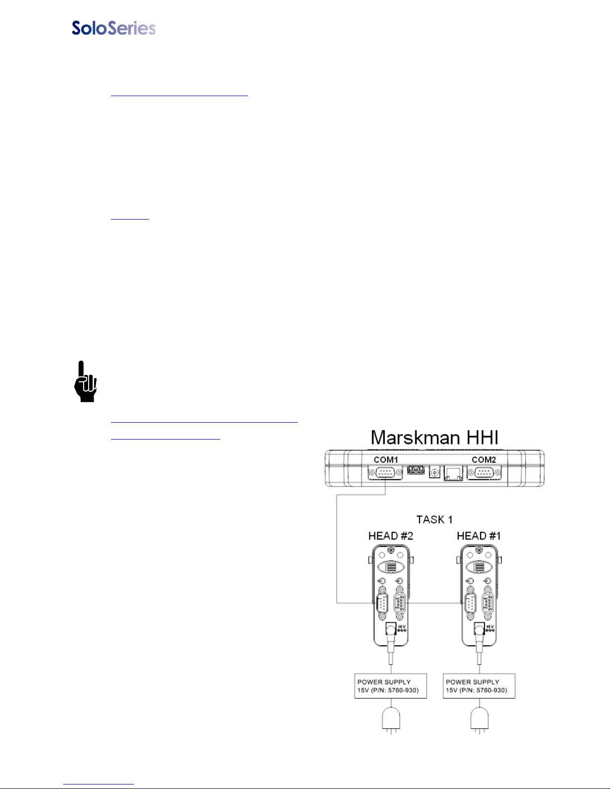
Marksman HHI Power Option
Cabling Diagrams
Single Task: The Marksman HHI controller draws its power from the daisy chain,
and the COM1 port is connected to the
last head in the chain.
5780-329 Operations Manual Rev J Page 34
Page 40
Thermal Jet
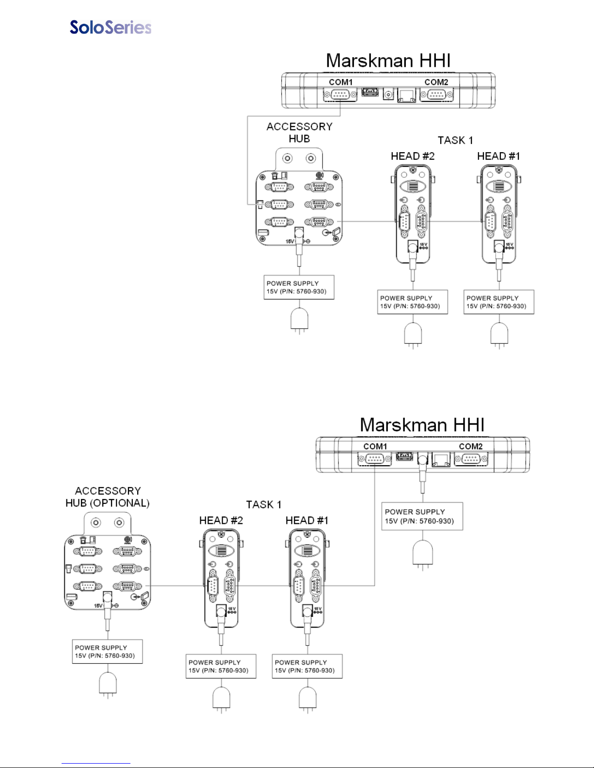
Single task with accessory hub:
The Marksman HHI draws its power
from the daisy chain, and is plugged
into the ’hand held’ connector on the
accessory hub; the accessory hub is
plugged into the last print head in the
daisy chain.
Single task with optional desktop power supply: The Marksman HHI COM1 port is connected to
the first print head in the daisy chain. If the accessory hub is used, it is connected to the last print
5780-329 Operations Manual Rev J Page 35
Page 41
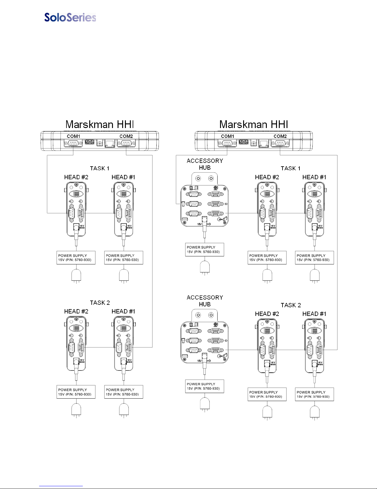
Thermal Jet
Dual task: The Marksman HHI draws
its power from the task 1 daisy chain;
COM1 is connected to the last print
head in the task 1 daisy chain, while
COM2 is connected to the first print
head in the task 2 daisy chain.
Dual task with accessory hub: The Marksman HHI
draws its power from the task 1 daisy chain; COM1 is
connected to the ’hand held’ connector on the accessory hub, and the accessory hub is then connected to
the last print head in the task 1 daisy chain. COM2 is
connected to the first print head in the task 2 daisy
chain, and the accessory hub is connected to the last
print head in the task 2 daisy chain.
5780-329 Operations Manual Rev J Page 36
Page 42
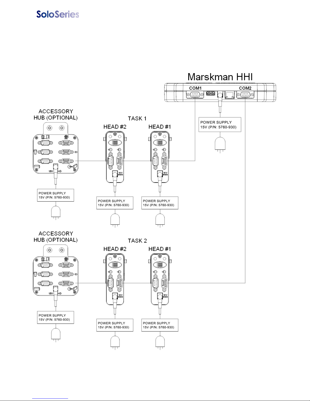
Thermal Jet
Dual task with optional desktop power supply: The Marksman HHI COM1 port is connected to
the first print head in the task 1 daisy chain, and COM2 is connected to the first print head in the
task 2 daisy chain. If either task uses the accessory hub it is connected to the last print head in the
daisy chain.
5780-329 Operations Manual Rev J Page 37
Page 43
Thermal Jet
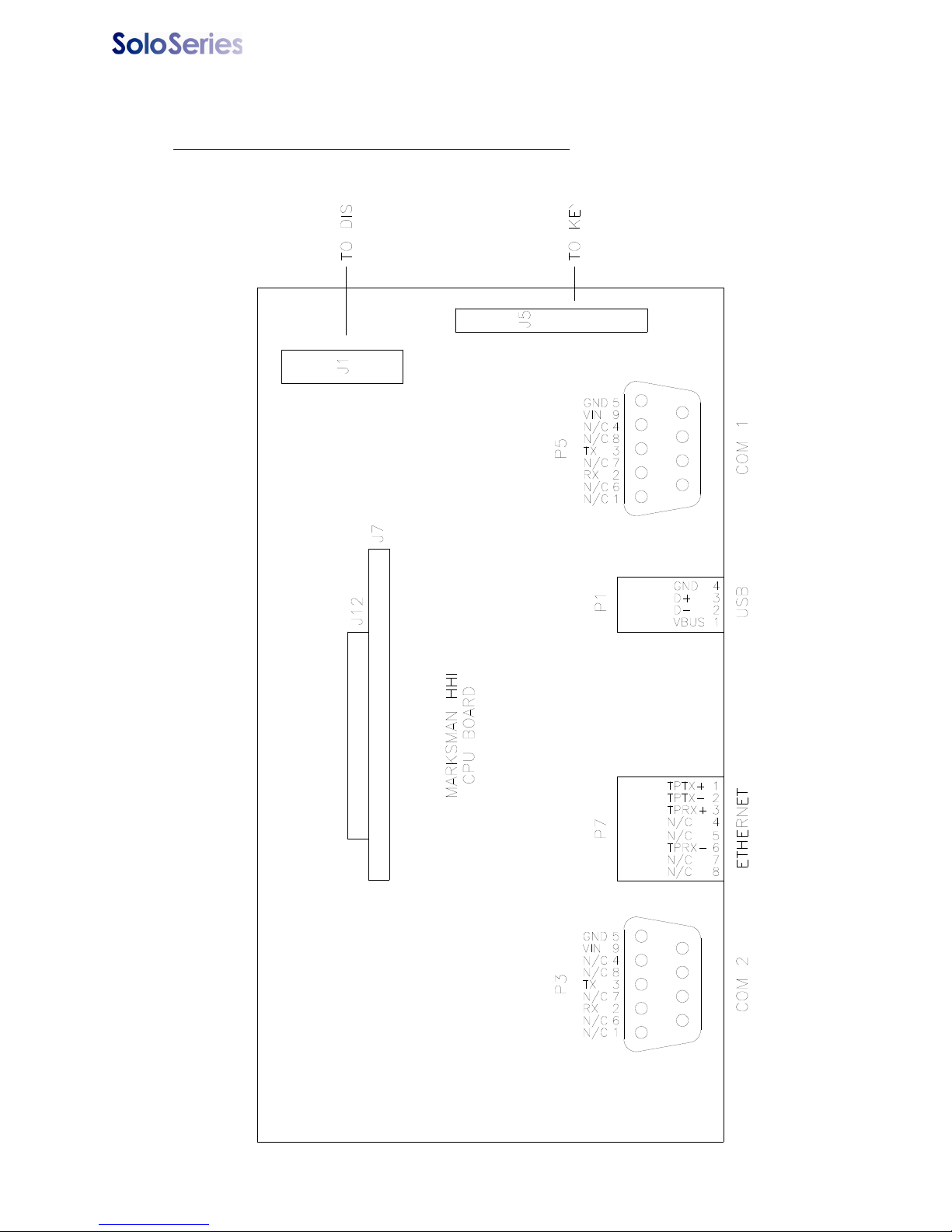
Interconnect Diagram
Marksman HHI Controller CPU Diagram
5780-329 Operations Manual Rev J Page 38
Page 44
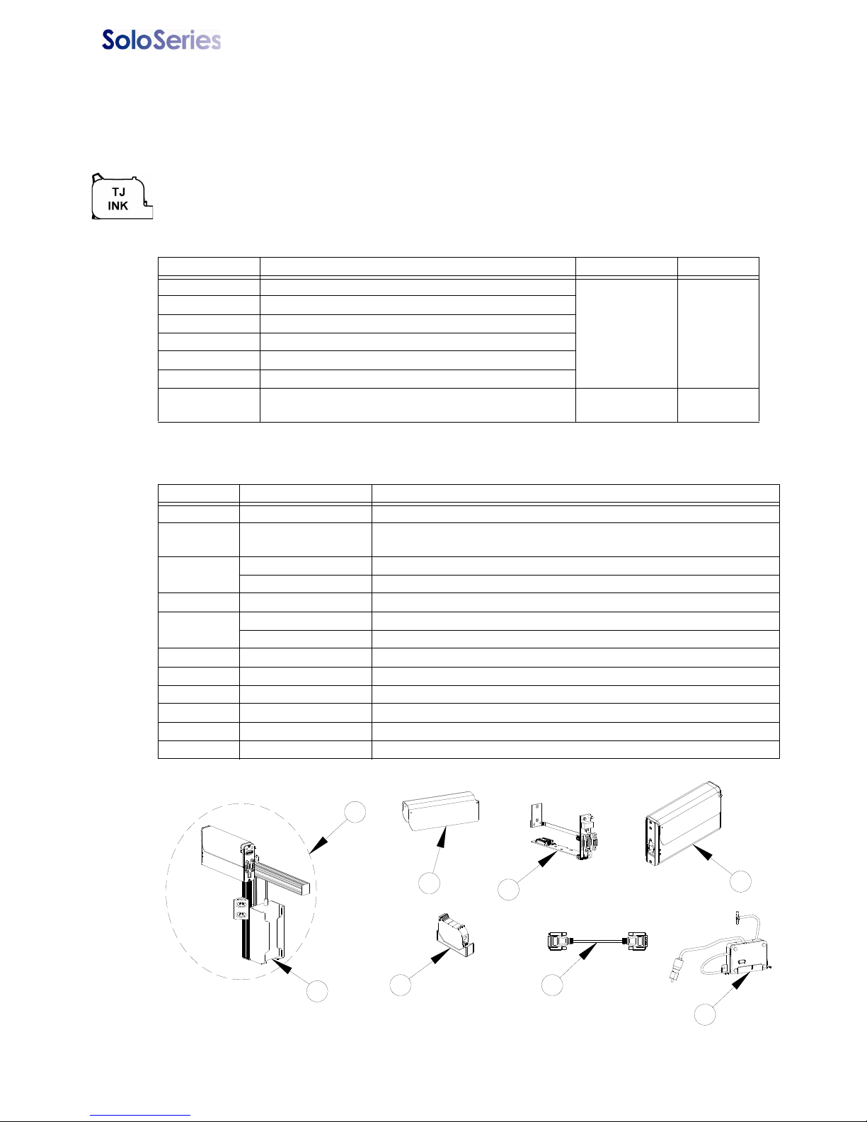
Thermal JetAppendix C: Part Numbers - Consumables and Service Parts
2
1
3
4
5
6
7
10
Appendix C: Part Numbers - Consumables and Service
Parts
Consumables
Ink Cartridge: The SoloSeries print head has been engineered and designed to work with Foxjet
ink cartridges. The SoloSeries’ Smart Level Ink Detection System, which provides ink level monitoring to ensure complete ink usage and product safety, will not be functional if used with non-Foxjet
ink cartridges.
Inks
Part No. Description Package Shelf Life
5780-201FX Solo 100 Porous Media, Black
5780-201RFX Solo 100 Porous Media, Red
5780-202FX Solo 200 Porous Media, Black, Extended Decap
5780-212FX Solo 300NP Non-Porous Media, Black
5780-235FX Solo 200 Barcode, Porous Media, Black
5780-220FX Solo 100 Porous Media, Bulk Ink, Black
5780-219FX Solo 100 Porous Media, Bulk Ink, Black
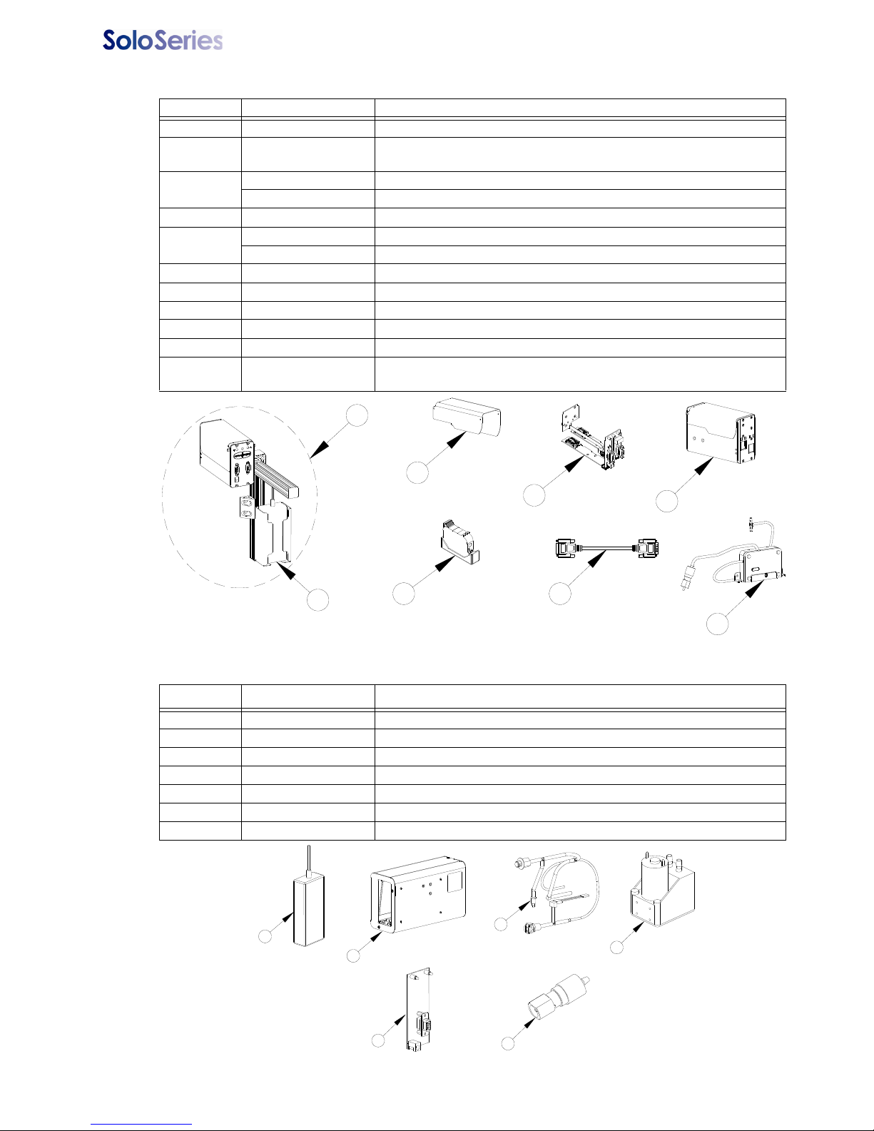
Service Parts
5 Cartridges 1 year
One 350ml Ink
Cartridge
1 year
SoloSeries45
Item Kit No. Description
1 5760-302 Power Supply, Print Head
2 5780-002FX
3
4 5780-226FX PCB Replacement Set
5
6 5780-208 Boot, Cartridge Cap
7 5780-319-10 Cable, Print Head, 10’
8 2464-182-25 Extension Cable, Print Head, 25’ (not shown)
9 2464-182-50 Extension Cable, Print Head, 50’ (not shown)
10 5780-231 Regulator Replacement, Bulk Ink
11 5780-229FX Upgrade Kit, Bulk Ink Print Head (Includes Item 3-bottom and Item 10)
5780-203FX Cover, Enclosure, Standard
5780-203BIFX Cover, Enclosure, Bulk Ink
5780-205FX Print Head Replacement, Standard
5780-217FX Print Head Replacement, Bulk Ink
SoloSeries45 Complete Print Head Kit with Mounting Bracketry, Power
Supply, Data Cable, & PC Software
5780-329 Operations Manual Rev J Page 39
Page 45
Thermal JetAppendix C: Part Numbers - Consumables and Service Parts
2
1
3
4
5
6
7
10
3
2
1
4
6
5
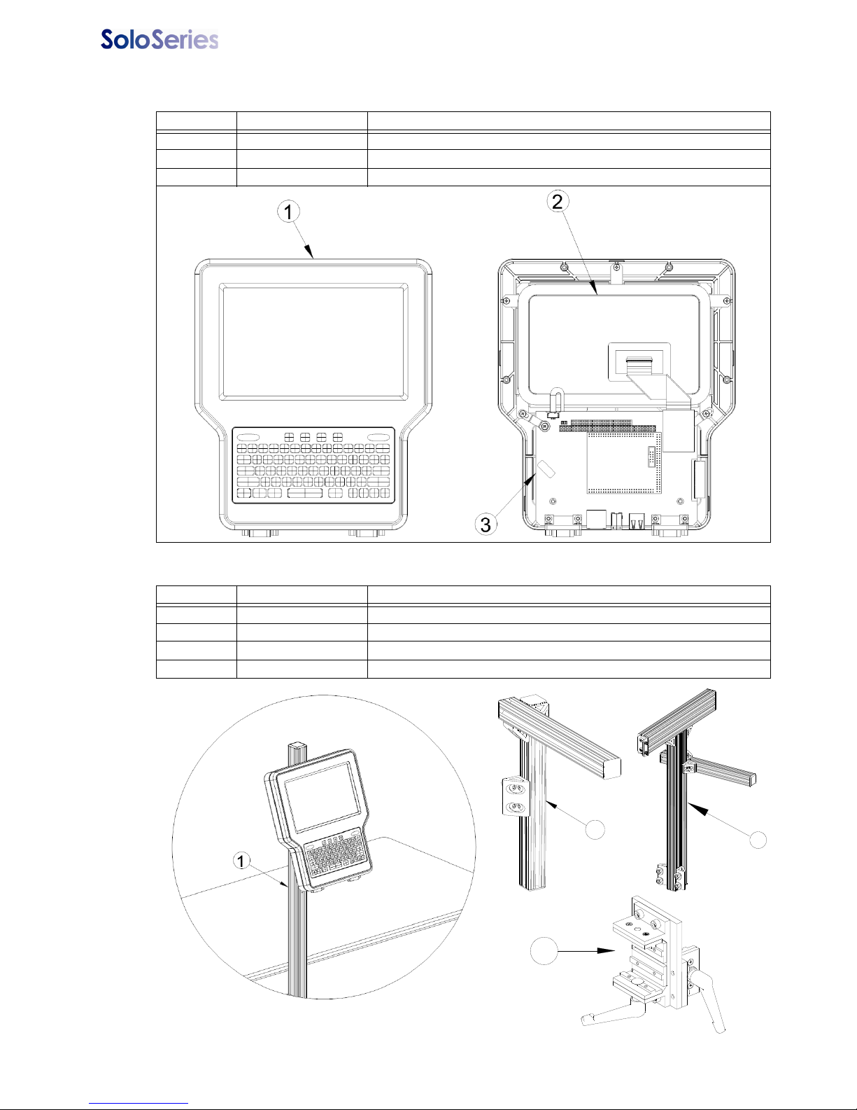
SoloSeries90
Item Kit No. Description
1 5760-302 Power Supply, Print Head
2 5780-007FX
3
4 5780-221FX PCB Replacement Set
5
6 5780-208 Boot, Cartridge Cap
7 5780-319-10 Cable, Print Head, 10’
8 2464-182-25 Extension Cable, Print Head, 25’ (not shown)
9 2464-182-50 Extension Cable, Print Head, 50’ (not shown)
10 5780-231 Regulator Replacement, Bulk Ink
11 5780-228FX
5780-225FX Cover, Enclosure, Standard
5780-225BIFX Cover, Enclosure, Bulk Ink
5780-215FX Print Head Replacement, Standard
5780-218FX Print Head Replacement, Bulk Ink
SoloSeries90 Complete Print Head Kit with Mounting Bracketry, Power
Supply, Data Cable, & PC Software
Upgrade Kit, Bulk Ink Print Head (Includes Item 3-bottom & 2 ea. Item
10)
SoloSeries IS
Item Kit No. Description
1 5760-302 Power Supply, 15VDC, Bulk Ink Supply
2 5780-216FX Replacement Bulk Ink Supply
3 5780-222 Internal Tubing and Fitting Replacement
4 5780-223 Vacuum Pump Replacement
5 5780-224 PCB Replacement
6 5780-209 Septum Fitting Replacement
7 5780-211 External Tubing and Fittings (not shown)
5780-329 Operations Manual Rev J Page 40
Page 46
Thermal JetAppendix C: Part Numbers - Consumables and Service Parts
2
3
4
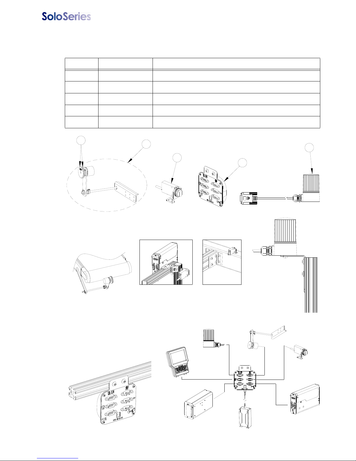
Marksman HHI
Item Kit No. Description
1 5780-015FX Marksman HHI Controller
2 5780-232 Color Display Replacement
3 5780-233 CPU PCB Replacement
Bracketry
Item Kit No. Description
1 5780-234 Bracketry, Marskman HHI Mounting
2 5780-200 Bracketry, SoloSeries Print Head Mounting
3 5780-227 Bracketry, Print Down
4 5780-230 Bracket, Linear, Tool-less
5780-329 Operations Manual Rev J Page 41
Page 47
Thermal JetAppendix C: Part Numbers - Consumables and Service Parts
4
2
1
3
5
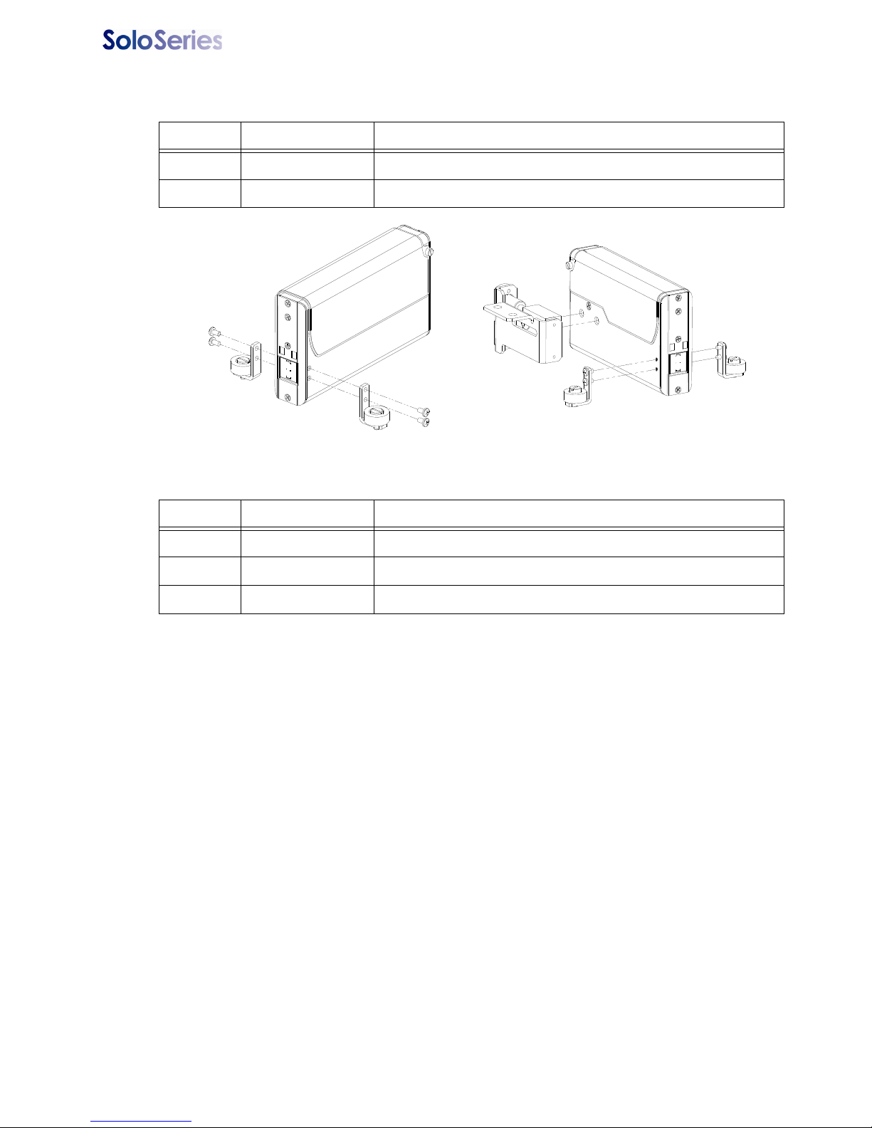
TYPICAL ENCODER
MOUNTING ON OPEN AREA
OF CONVEYOR BELT
TYPICAL ACCESSORY
HUB MOUNTING
TYPICAL BEACON
MOUNTING
TYPICAL PHOTOCELL MOUNTING
BRACKETRY
MOUNTING
CONVEYOR
MOUNTING
BULK INK
SUPPLY
POWER
SUPPLY
INK STATUS
BEACON
ENCODER
PRINT HEAD
PHOTOCELL
ACCESSORY
HUB
ACCESSORY HUB CONNECTIVITY
MARKSMAN HHI
Optional Equipment
Encoder, Photocell, Accessory Hub, and Beacon
Item Kit No. Description
1 5760-820-IJ Encoder Assembly with Mounting Bracket & 25’ Cable
2 5765-206 Encoder O-ring Replacement
3 5760-383 Photocell
4 5780-010FX Accessory Hub with Power Supply
5 5780-214 Beacon
‘
5780-329 Operations Manual Rev J Page 42
Page 48
Thermal JetAppendix C: Part Numbers - Consumables and Service Parts
Roller Bracket Only
Roller & Retractor Bracketry
Roller & Retractor Bracketry
Item Kit No. Description
1 5780-206 Roller Bracket Only
2 5780-207 Roller and Retractor Bracket
Maintenance
Item Kit No. Description
1 1901-398 Hand Cleaner, Reduran
2 5760-832 Sponge Swabs, Qty. 100
3 6600-171 Lint-free Wipe Cloths
5780-329 Operations Manual Rev J Page 43
Page 49
Thermal Jet Appendix D: File Backup and Restore
Appendix D: File Backup and Restore
Use these procedures for making archival copies of the system configuration and print
message files, and for preserving the system's configuration and print messages during
firmware upgrades. File types saved during a backup are .cfg, .prd, .bmp and .alp. These
are the system configuration files, message files, logo files and label files, respectively.
These instructions assume the Marksman HHI controller is already connected, via Ethernet, to a PC. If not, please refer to
Marksman HHI” on page 47
1. Obtain the Marksman HHI controller's IP address. Most Marksman HHI controllers
have an IP address of
other Marksman HHIs or other devices. If the IP address is unknown, go to the controller, and from the
• Touch the
• Touch the
Screen.
• Touch the
• Record the Marksman HHI's IP address (it's the top one).
Control Panels button to open the Control Panels Menu.
IP Addresses tab to display the system's IP addresses.
Home Screen:
Network button on the Control Panels Menu to open the Network Setup
.
10.1.2.3. It may be different if the controller is networked with
“Appendix E: Configuring a PC to Communicate with
2. On the PC, start Microsoft Internet Explorer (must be version 3.2 or higher) or another
web browser.
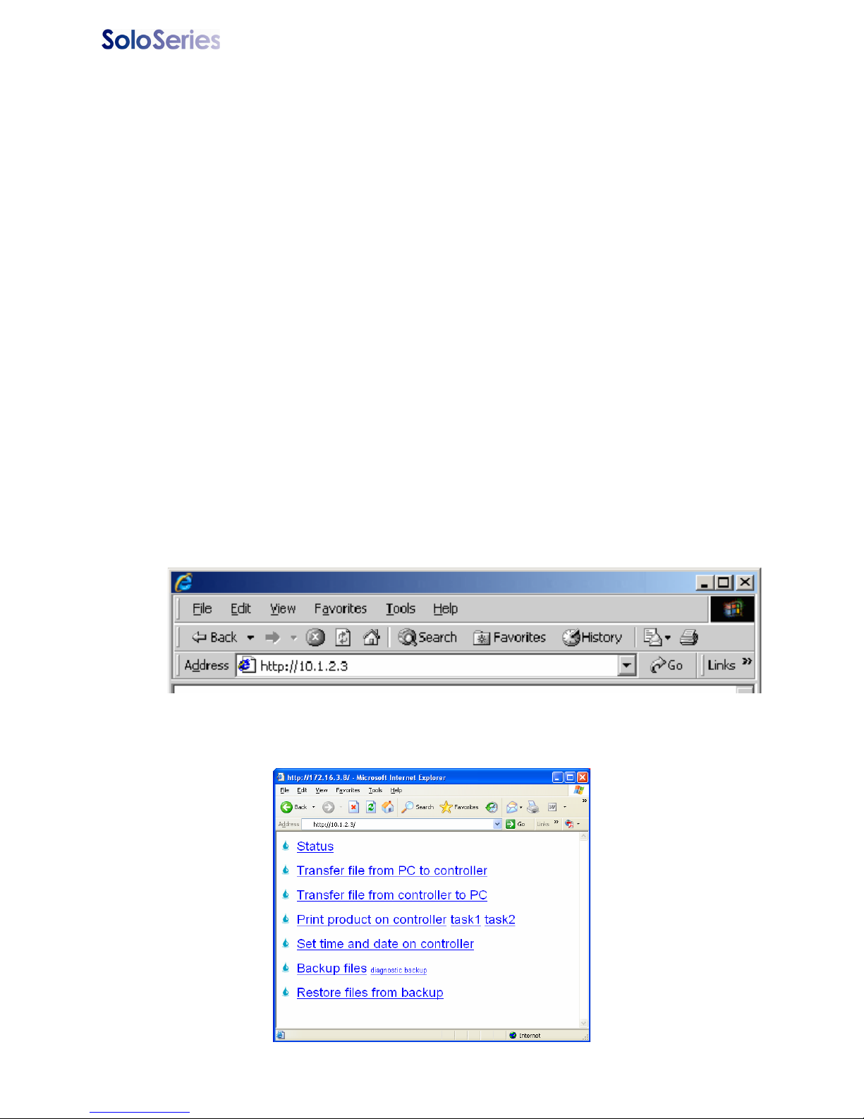
3. In the browser's address box type in "http://", followed by the controller's IP address.
See the illustration below:
4. Press
Enter. The web page shown below should appear.
5780-329 Operations Manual Rev J Page 44
Page 50
Thermal Jet Appendix D: File Backup and Restore
File Backup
To backup the system files, click the
Backup files link.
The dialog box
shown at right (or a
similar dialog box)
will appear.
Click the
Save button. A Save As dialog appears.
The Marksman HHI files backed up are compressed and put into a single file, and are
given the default name and file extension
ventions, the backup file may be renamed and given any extension, and saved in any
folder desired. To save the backup file with an extension other than .tgz, open the
type combo box and select All Files.
5780-329 Operations Manual Rev J Page 45
backup.tgz. Following normal Windows® con-
Save as
Page 51
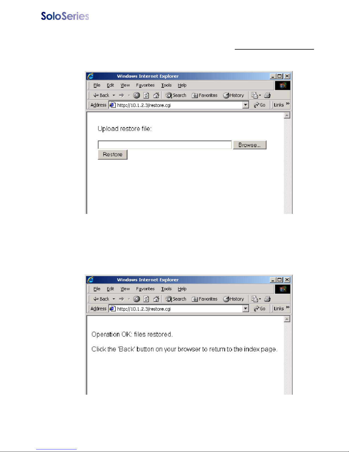
Thermal Jet Appendix D: File Backup and Restore
Restoring Backed-Up Files
To restore the controller’s backed up system files, click the Restore files from backup
link. The web page shown below appears.
Click the
Click the
Browse... button to locate and select the backup file to be sent to the controller.
Restore button to send the file to the controller. If the file transfer is successful,
the web page shown below will be displayed.
5780-329 Operations Manual Rev J Page 46
Page 52
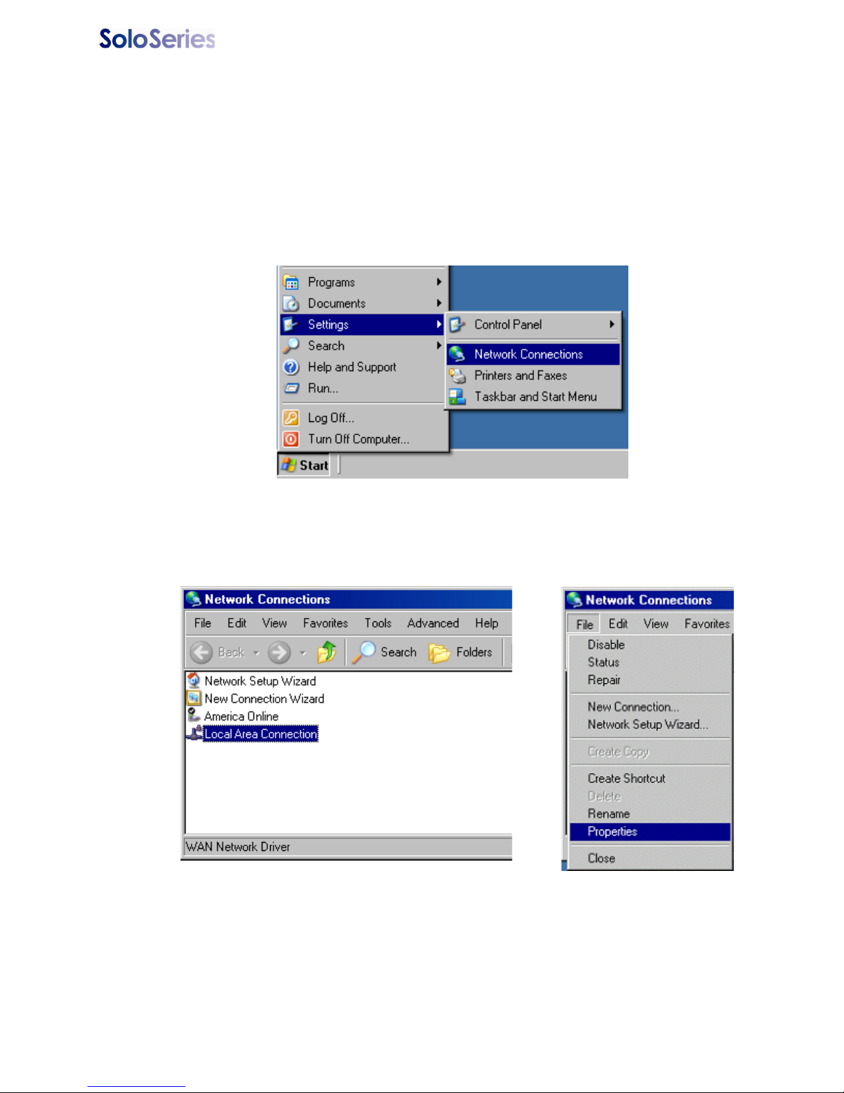
Thermal Jet Appendix E: Configuring a PC to Communicate with Marks-
Appendix E: Configuring a PC to Communicate with Marksman HHI
This appendix has instructions for setting the IP address and subnet mask of the PC so it
can communicate with the Marksman HHI Controller. Included are instructions for Windows
XP®, Windows 2000®, Windows 98®, and Windows 95®.
Windows XP®
1. Open the Start menu; select Settings, then Network Connections.
2. Click
Local Area Connection, then open the File menu and select Properties.
5780-329 Operations Manual Rev J Page 47
Page 53
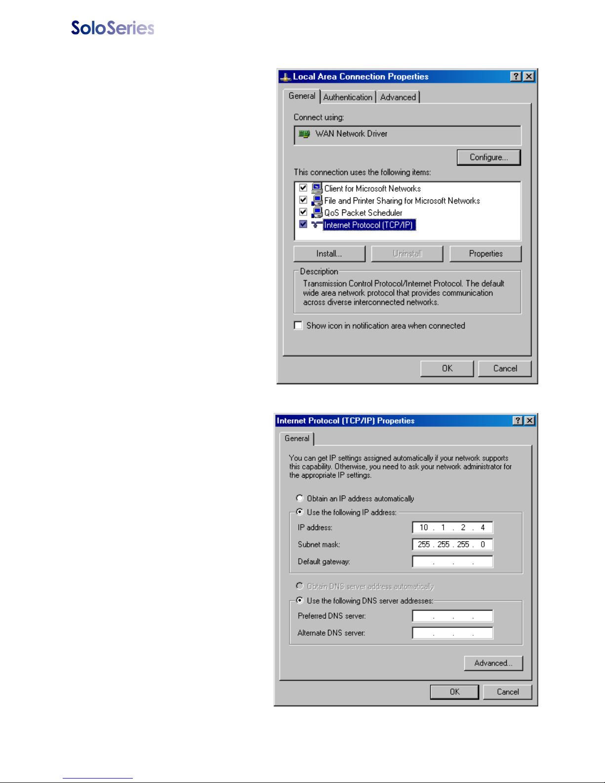
Thermal Jet Appendix E: Configuring a PC to Communicate with Marks-
3. Select Internet Protocol
(TCP/IP)
then click the
Properties button.
4. Click the
IP address
Use the following
radio button.
Enter an IP address of
10.1.2.4, a subnet mask of
255.255.255.0, and click
OK button.
the
5780-329 Operations Manual Rev J Page 48
Page 54
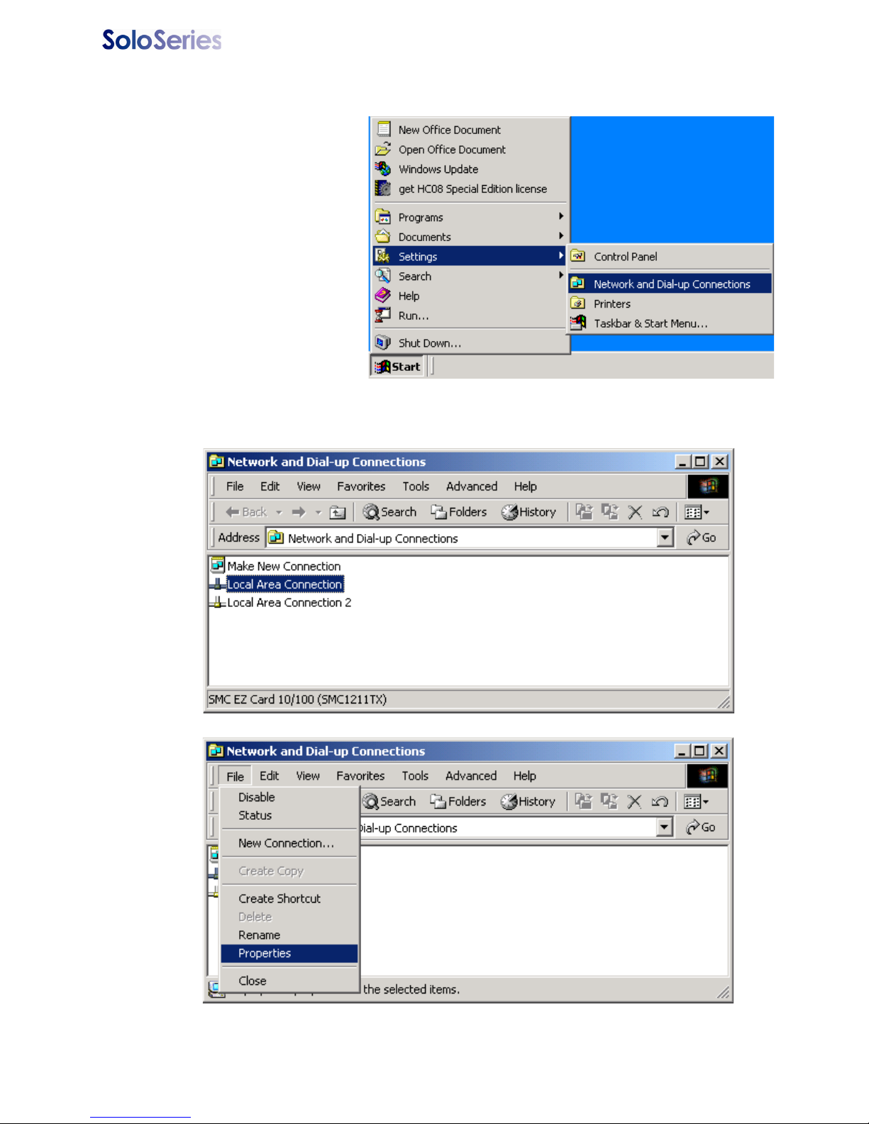
Thermal Jet Appendix E: Configuring a PC to Communicate with Marks-
Windows 2000®
1. Open the Start menu;
select
Network and Dial-up
Connections.
2. Click the desired connection, then open the File menu and select Properties.
Settings, then
5780-329 Operations Manual Rev J Page 49
Page 55
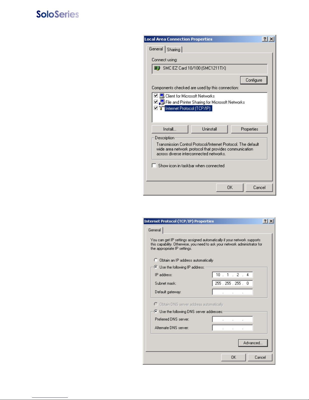
Thermal Jet Appendix E: Configuring a PC to Communicate with Marks-
3. Select Internet Protocol
(TCIP/IP)
then click the
Properties button.
4. Click the
IP address
Use the following
radio button.
Enter an IP address of
10.1.2.4, a subnet mask of
255.255.255.0, and click the
OK button.
5780-329 Operations Manual Rev J Page 50
Page 56

Thermal Jet Appendix F: Font Samples
Appendix F: Font Samples
Arial 30 - 1/10 in (2.54 mm):
Arial 75 - 1/4 in (6.35 mm):
AaBbCcDdEeFf
1234567890
Arial 150 - 1/2 in (12.7 mm):
AaBbCcDdEeFf
1234567890
AaBbCcDdEeFf
1234567890
For best results printing the next two fonts use an external encoder. The top images were
printed with an external encoder. The lower images were printed using the "Auto Speed
Detect" mode (without external encoder) from the controller or GUI software.
Arial 225 - 3/4 in (19.05 mm):
Arial 300 - 1 in (25.4 mm):
5780-329 Operations Manual Rev J Page 51
Page 57
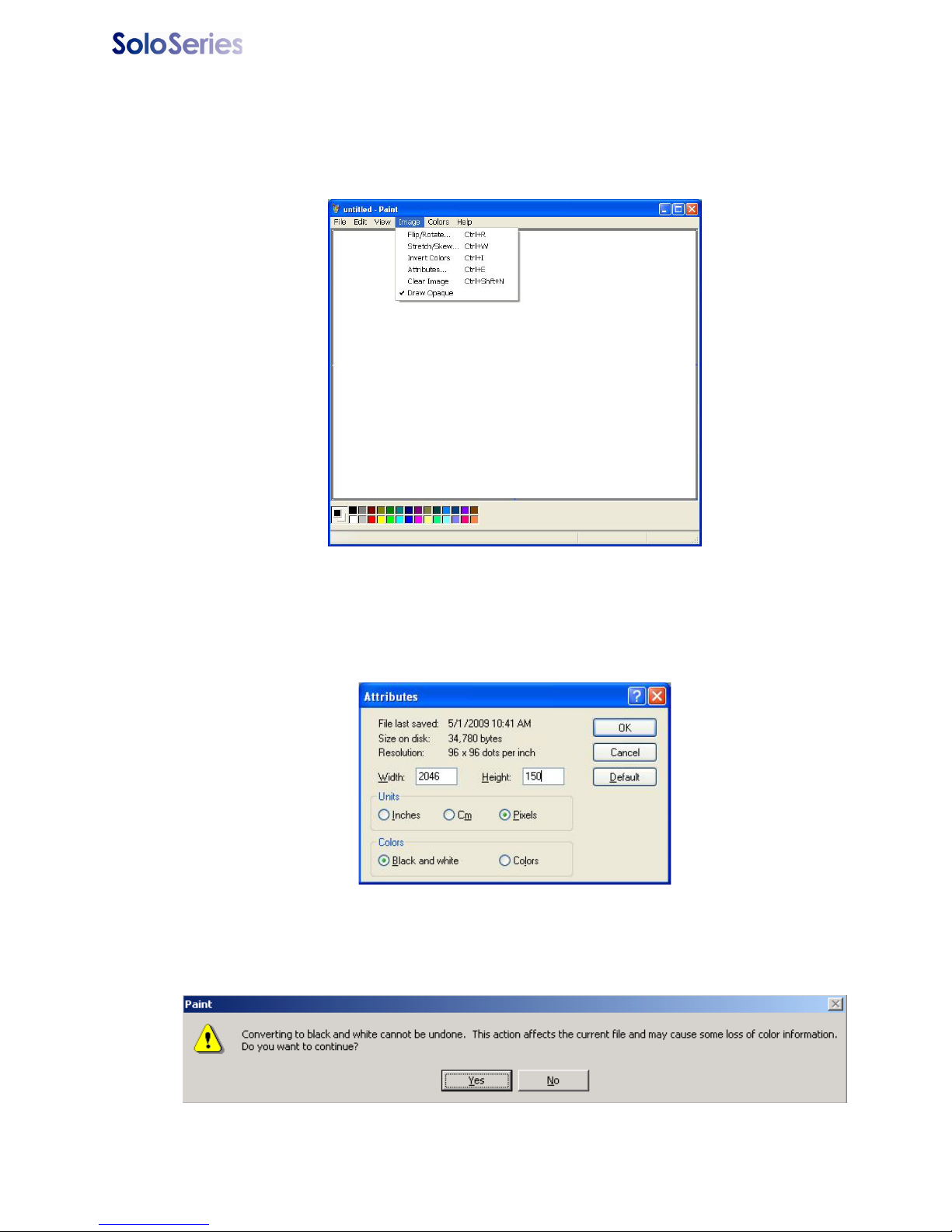
Thermal Jet Appendix G: Creating Logo Files
Appendix G: Creating Logo Files
Open Paint from a PC by selecting Start, Programs, Accessories, and then Paint.
Bring up the Attributes dialog box by selecting Image and then Attributes.
Enter the Width and Height of the logo in Pixels. For practical purposes the maximum
height of a logo is150 pixels if the logo is prined with a SoloSeries45 print head, and 300
pixels if printed with a SoloSeroes90 print head. The absolute maximum logo height is
1200 pixels, but logos that cross print head boundaries will likely exhibit registration problems when printed. Maximum logo width is 32,767 pixels, or print columns (109.22 in / 2.77
n when printed at 300 dpi.) Select
Choose
Yes at the screen prompt to convert to black and white if applicable.
Black and white for the Colors.
5780-329 Operations Manual Rev J Page 52
Page 58
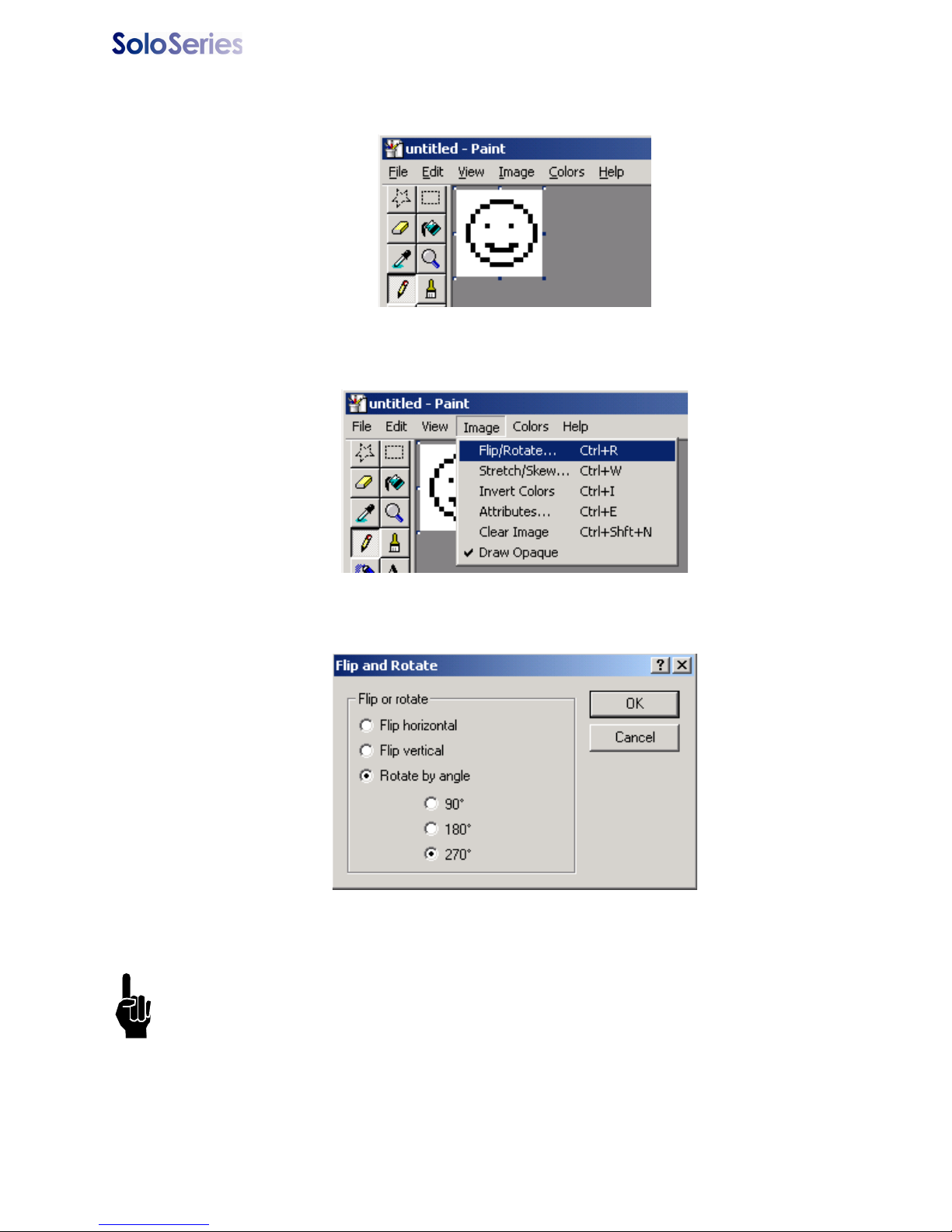
Thermal Jet Appendix G: Creating Logo Files
Define the pixels of the logo using the drawing tools, or copy and paste an image from
another document.
Bring up the
Select
Rotate by angle, then 270°. Click Ok.
Flip and Rotate dialog by selecting Image, Flip/Rotate.
From the
File Menu, select Save As and save the logo in a directory location that you will
remember.
NOTE: If the print heads are being controlled via a PC using the InkJet Demo software
rather than an Marksman HHI controller, then store the logo in
Jet\bmps
5780-329 Operations Manual Rev J Page 53
.
c:\Program Files\Ink-
Page 59
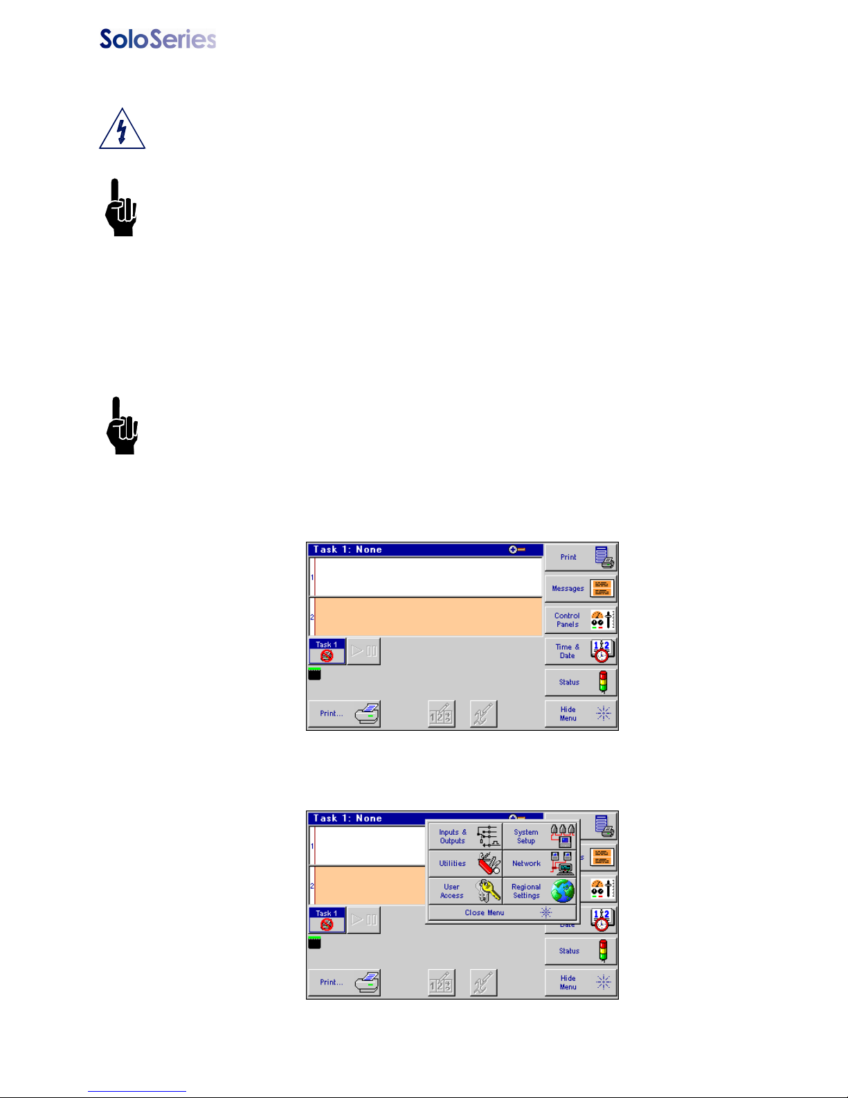
Thermal JetAppendix H: Uploading Files to the Print Head and File Man-
Appendix H: Uploading Files to the Print Head and File Management
CAUTION: Power should be disconnected from the print head prior to connecting or disconnecting any external devise, including: PC, handheld, controller or print head daisy
chain cables. Electrical arcing may occur if external cabling is connected or disconnected
while power is supplied to the unit.
NOTE: Files can
not be transferred while thermal jet print heads are printing. Pause print
first.
Font and bitmap (logo) files are uploaded to the print head via the Marksman HHI controller
or PC Inkjet Demo software using the File Manager on the System Utilities screen. In addition to uploading files, the File Manager also allows removal of files from the print heads;
however, files cannot be copied from a print head. During the upload process, files are
simultaneously added to or removed from all print heads on the daisy chain being
addressed. Operations on an individual print head are possible only when it is the sole
head on the daisy chain.
NOTE: A .bmp (logo) or .fnt (font) file must reside on both the controller and print head(s) to
be correctly selected, displayed, and printed. Refer to “Appendix D: File Backup and
Restore” on page 44, step 4. Select the "Transfer file from PC to controller" option. Browse
the PC and locate the BMP. Select Ok to transfer the file to the controller.
To access the File Manager utility:
1. Touch the
Control Panels button on the Home screen.
2. Touch the
5780-329 Operations Manual Rev J Page 54
Utilities button; the System Utilities screen is displayed.
Page 60
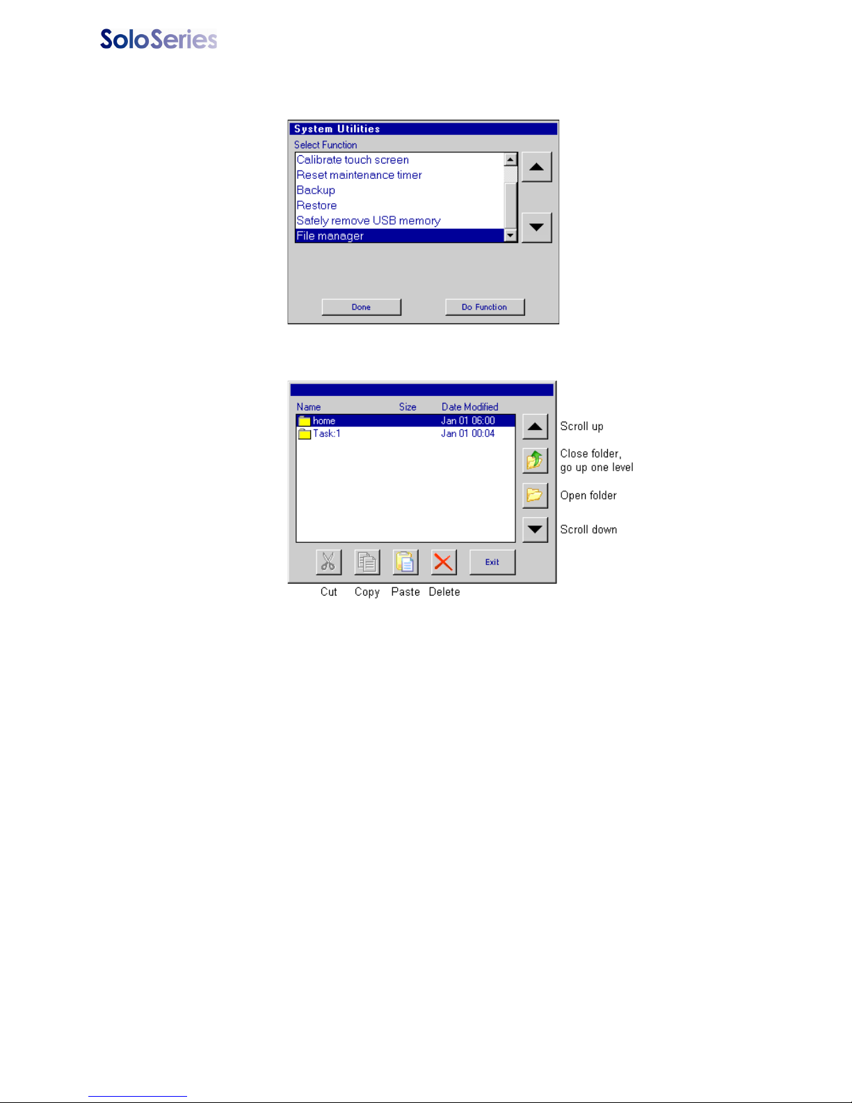
Thermal JetAppendix H: Uploading Files to the Print Head and File Man-
3. Scroll to the bottom of the utilities list and select File manager.
4. Touch the
The
home folder contains all folders and files related to Marksman HHI operation; task
folders,
Task:1 and Tas k :2 (not shown), contain the font and logo files present on the print
Do Function button; the File Manager screen is displayed.
heads on their respective tasks. Task folders are present only when one or both of the controller's serial ports are configured for serial print heads. Not shown above are folders
usb0 and usb1, which are displayed when USB drives are plugged into the one or both of
the Marksman's USB ports. The Marksman HHI controller will show only
usb0 as it has
only one USB port. USB folders are not displayed when running the PC InkJet Demo program.
Adding Logo and Font Files
So that they may be correctly selected, displayed, and printed, logos and fonts must be
stored on both the controller and the print head(s).
On the controller, logos are stored in the folder
/home/fnts. Files are automatically placed in the correct folders when transferred to
folder
the controller from a PC using a web browser; they must be manually placed in the correct
folder when being transferred from a USB drive using the copy-and-paste method.
Uploading a file to a print head loads the file on all print heads on the task. A step-by-step
example of uploading a logo file to task 1 print heads follows. The example assumes the
file being uploaded is already on the controller.
5780-329 Operations Manual Rev J Page 55
/home/bmps, and fonts are stored in the
Page 61
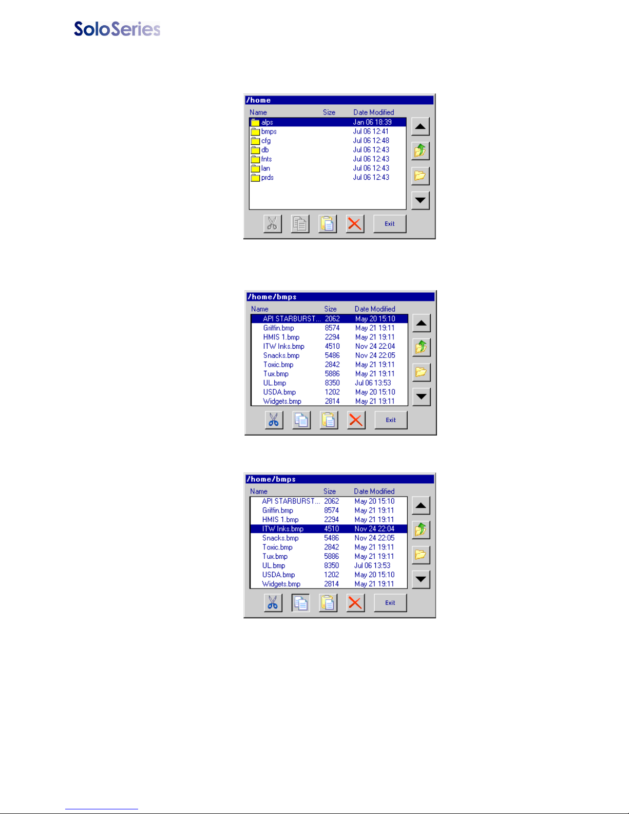
Thermal JetAppendix H: Uploading Files to the Print Head and File Man-
1. Open the home folder. The display shows the available folders and files:
2. The display shows a list of available files. Highlight the
bmps folder with the up /
down arrows and open it:
3. Select the file to be uploaded to the print head(s), and then touch the
Close folder,
go up one level
Copy button.
4. Close the
5. Close the
5780-329 Operations Manual Rev J Page 56
bmps folder, returning to the home folder level.
home folder, returning to the top level.
Copy
Page 62
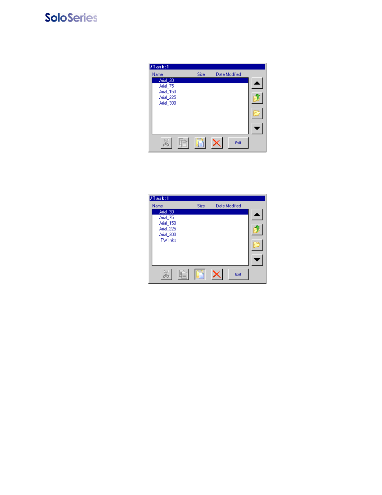
Thermal JetAppendix H: Uploading Files to the Print Head and File Man-
6. Select and open the Tas k :1 folder. The display shows a list of all files on print head
#1 only; it is assumed that all print heads have the same files.
Open
7. Touch the
Paste button. The file is uploaded to all print heads on the task, after
which the file list is updated, showing the newly added file.
Paste
While the file is uploading an hourglass is displayed, and the red LED on the back of each
of the print heads on the task’s daisy chain blinks.
Removing a File
5780-329 Operations Manual Rev J Page 57
Page 63
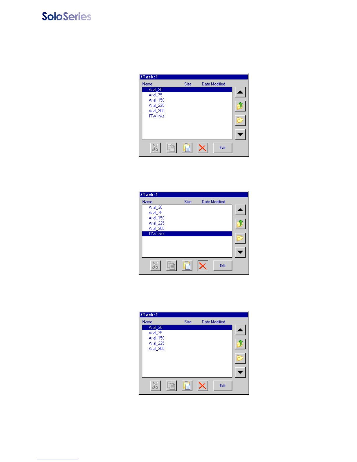
Thermal JetAppendix H: Uploading Files to the Print Head and File Man-
To remove a file from all print heads on a task:
1. Select and open the task folder.
Open
2. Select the file to be deleted, and then touch the
Delete
3. The file is deleted and the file list updated:
Delete button.
5780-329 Operations Manual Rev J Page 58
Page 64

Thermal Jet Appendix I: Communicating Directly to the Print Head
Appendix I: Communicating Directly to the Print Head
The 1/2" (12.7 mm) and 1" (25.4 mm) print heads can be controlled by direct serial communication. Refer to the serial protocol document 5780-316N when communicating directly to
the print head without the use of a controller or the pc GUI software interface.
5780-329 Operations Manual Rev J Page 59
Page 65
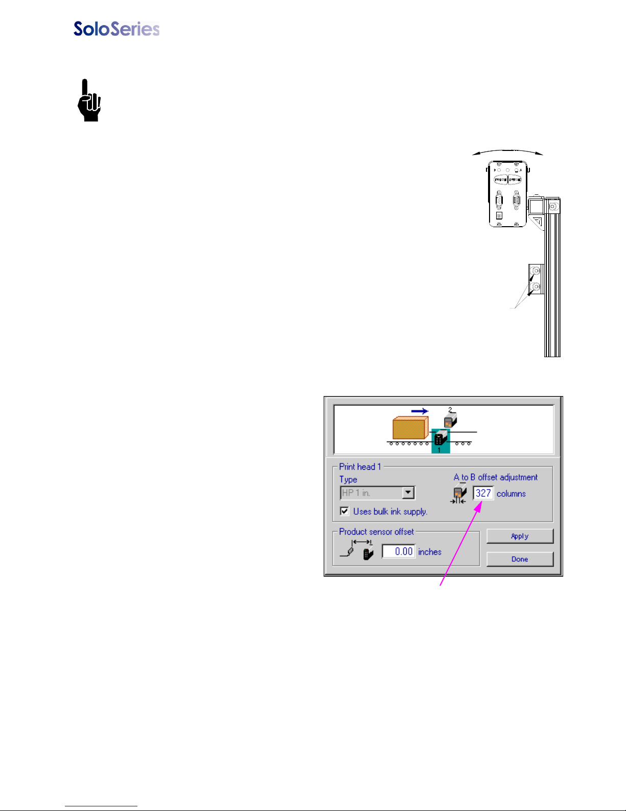
Thermal Jet Appendix J: Aligning the 1" (25.4 mm) Print Head
LOOSEN
THESE
SCREWS
Appendix J: Aligning the 1" (25.4 mm) Print Head
NOTE: This procedure assumes that the user has already installed the equipment per the
installation procedure (See “Section 2: Quick Start” on page 2.). In addition, an encoder
should be used for the best horizontal alignment between both print cartridges.
1. Ensure the front face of the print head is perpendicular to the
substrate being printed.
2. Create a message using the Arial 300 font and run a print sample
with the actual product.
3. Observe the vertical overlap or gap between the two cartridges. If
there is significant overlap, loosen the mounting screws and
rotate the print head bracketry counter-clockwise. If there is a
gap between the halves, rotate the bracketry clockwise.
4. Snug the mounting screws and run another print sample. If the
overlap or gap is not acceptable, then repeat the previous step.
5. Repeat the previous two steps until the two cartridges are
matched vertically.
6. Fully tighten the mounting hardware.
7. Now observe the horizontal alignment of the characters.
8. Horizontal misalignment can be compensated electronically through the controller or
GUI software program by navigating
to the
Control Panels from the
Home Screen, pressing System
Setup
, and then touching the print
head in question.
9. An adjustment box, labeled as
offset adjustment,
is available to
A to B
compensate for any horizontal misalignment. Increase or decrease the
number in the box and press
Apply.
The next print will have adjusted the
alignment one way or the other.
Repeat this step until the desired horizontal alignment is achieved.
Press on this box to highlight,
and then type in an adjustment
value
5780-329 Operations Manual Rev J Page 60
Page 66
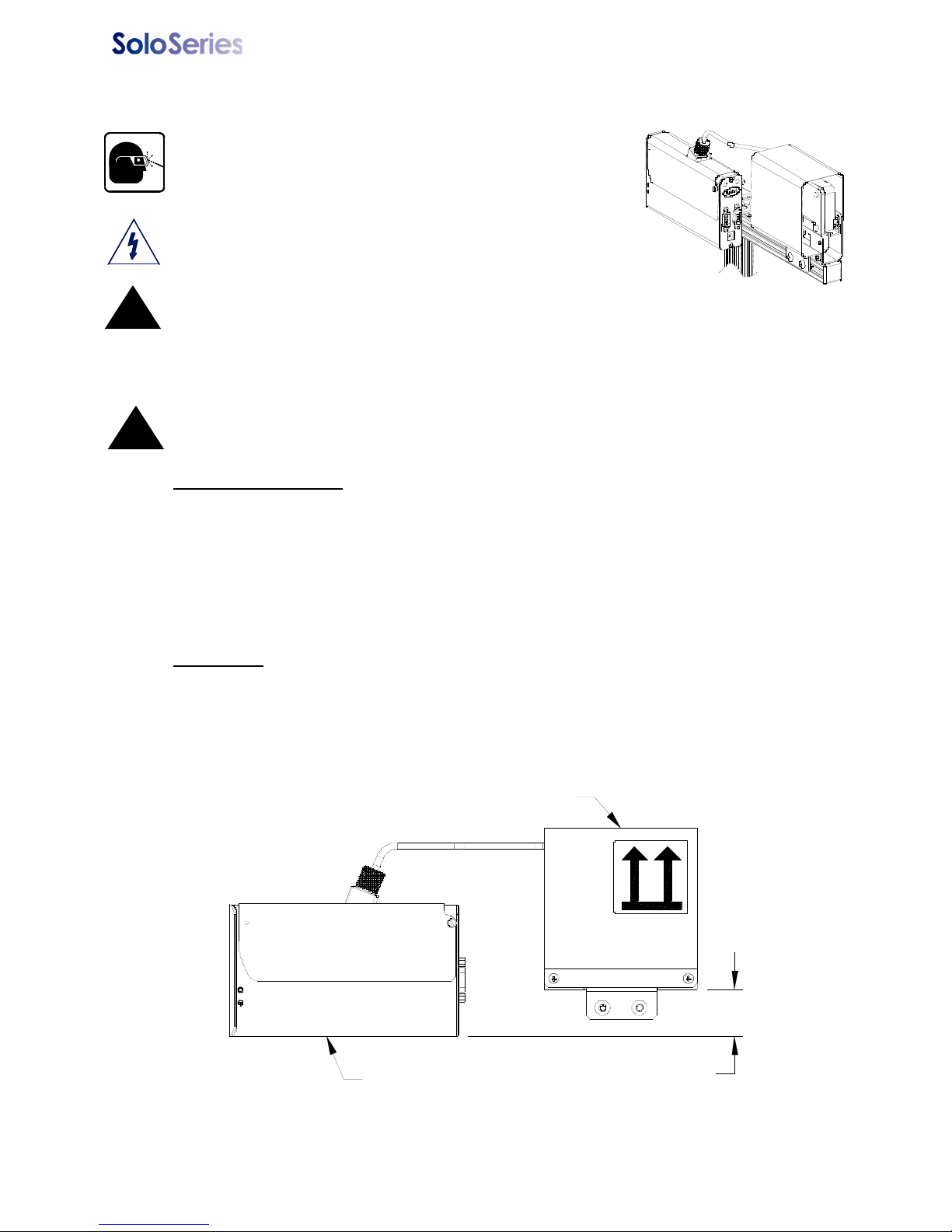
Thermal Jet Appendix K: Bulk Ink Supply
Print Head
Regulator
For the system to function properly it is critical that the regulator
be positioned appropriately in relation to the print head as shown.
1-1/4"±1/8"
Appendix K: Bulk Ink Supply
Wear safety goggles when working with industrial
inks and solutions!
WARNING: Disconnect power during installation.
CAUTION: Sudden impact to the installed print head
!
(caused by moving the conveyor with the print system
attached or moving the print system from one location to another) can cause ink to
seep out the front of the print cartridge. To keep this from happening disconnect
septum fitting, remove print cartridge, and depressurize the bulk ink supply before
moving the print system.
CAUTION: Failure to properly bleed the air from the ink lines before connecting the
septum fitting to the print cartridge could damage the print cartridge.
!
System Components
• Print Head
• Regulator
• Bulk Ink Supply
• Controller or PC (Marksman HHI controller requires the optional Hub (below))
• Beacon (optional)
• Hub (optional)
Installation
1. Mount the print head(s), bulk ink supply, and controller (if applicable). Note: The
bulk ink supply can be a maximum of three feet above or below the print head(s).
The regulator must be mounted on the same horizontal bar as the print head. See
page 64 for print down application.
5780-329 Operations Manual Rev J Page 61
Page 67
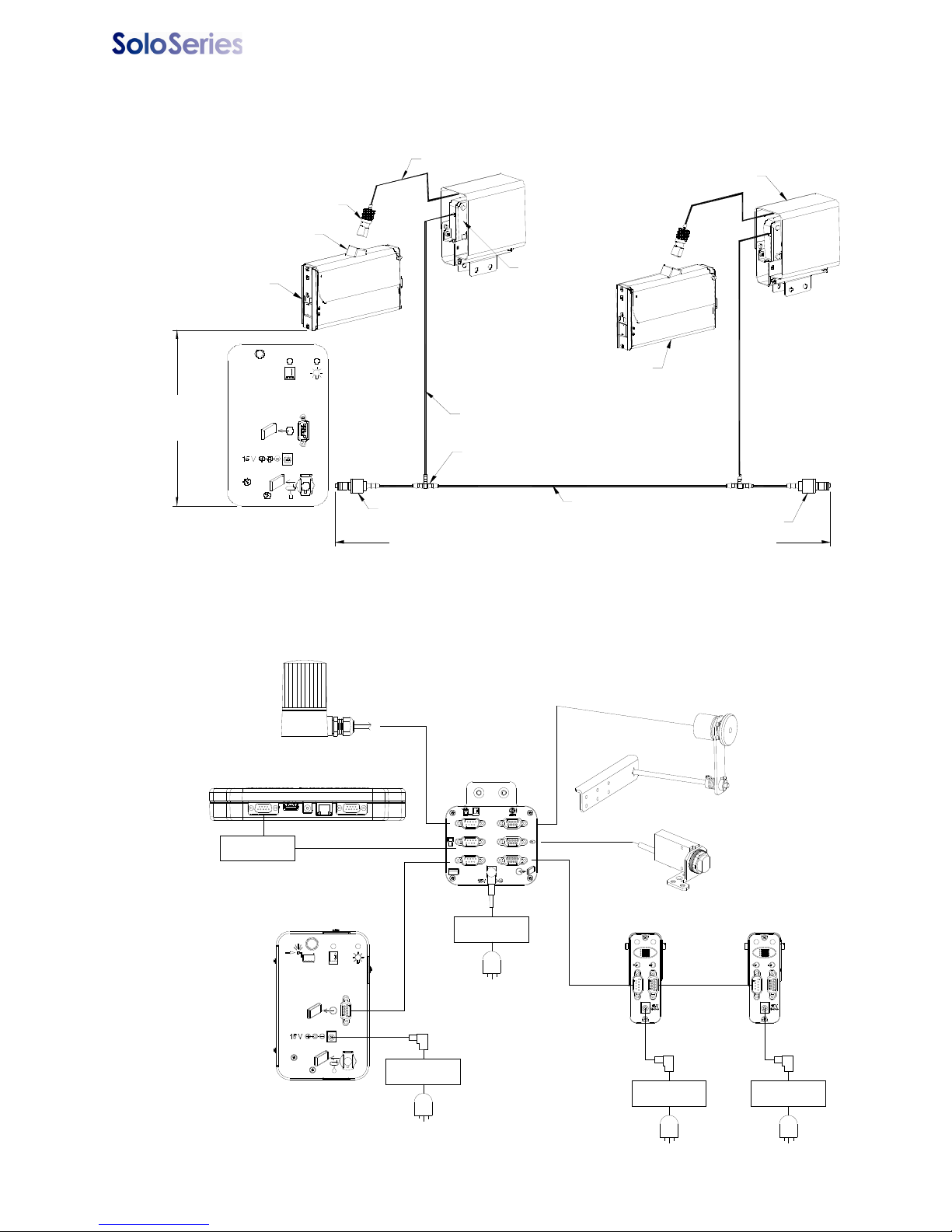
Thermal Jet Appendix K: Bulk Ink Supply
Ink service port
(1900-757)
Fitting, t ee, reduc er, 1/8" t o 3/32"
(5361-349)
Tubing, 3 /32 ID x 5/32 OD
(1303-56 4)
Bulk Ink Supply
Trunk line
Tubing , 1/8" ID x 1/4" OD
(1301-468)
Bulk Ink Print head 2
Reg ulator (5780-1 05)
Tubing, 1/ 8" ID x 3/16" O D (1303 -563)
Fitting assembly, s eptum to
1/8" b arb (5780-393)
Bulk Ink Print head 1
Bulk Ink cartridge
TUBING DIAGRAM
3' Ma ximum vertical
rise from bulk ink
supply to print head
Orient as shown
10' Max imum ho rizontal sepa ration bet wee n Bulk Ink Sup ply and f urtherst Print H ead
Valve, Q D to 1/ 8" barb
(1900-75 7)
BULK INK SUPPLY
POWER SUPPLY
15V (P/N: 5760-930)
POWER SUPPLY
15V (P/N: 5760-930)
POWER SUPPLY
15V (P/N: 5760-930)
BEACON
(P/N: 5780-214)
ENCODER
(P/N: 5760-820-IJ)
CABLE, SERIAL
(P/N: 5780-319-10)
CABLE, SERIAL
(P/N: 5780-319-10)
CABLE, SERIAL, F/F
(P/N: 5780-616-06)
PRINT HEAD 2
PRINT HEAD 1
PHOTOCELL
(P/N: 5760-383)
ACCESSORY
HUB
POWER SUPPLY
15V (P/N: 5760-930)
MARKSMAN HHI
2. Make ink line connections from the bulk ink supply to the regulator per the diagram
below; the trunk line should be made as short as practical. (CAUTION: Do not connect septum fitting to the print cartridge at this time.)
3. Make all electrical connections as shown, including all power connections per the
diagram below.
5780-329 Operations Manual Rev J Page 62
Page 68
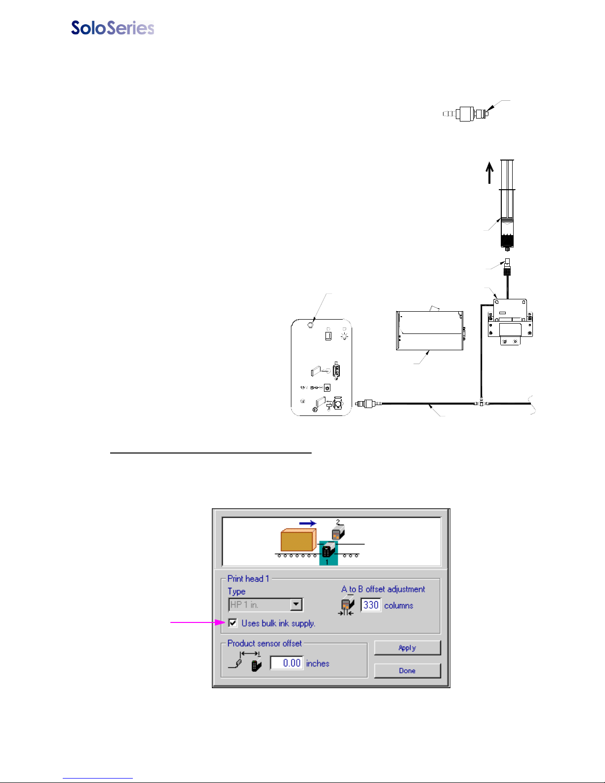
Thermal Jet Appendix K: Bulk Ink Supply
Valve
Trunk line
Bul k Ink Su pply
Syr ing e
Regulator
Print head
Septum fit ting
Pres sure re lief valve
4. Insert print cartridges into the print heads and a 350 ml ink cartridge in the bulk ink
supply.
5. Bleeding air out of the ink lines:
a) At the ink service port of the trunk line, depress the valve
of the fitting in short spurts into a rag or trash can. Continue this until all air has been bled out of the main trunk
line.
b) Connect the syringe
(2466-166, supplied with
the bulk ink system) to the
septum fitting. While holding the syringe and tubing
above the regulator,
slowly draw the air out of
the ink line. Once all of
the air is out of the ink line
and a small amount of ink
is drawn into the syringe,
disconnect the syringe
and plug the septum fitting
into the print cartridge.
Repeat for each regulator.
Configuring system for bulk ink supply
At the controller (or PC software) in the print head setup, select the "Uses bulk ink supply"
check box for each print head in the daisy chain.
5780-329 Operations Manual Rev J Page 63
Page 69
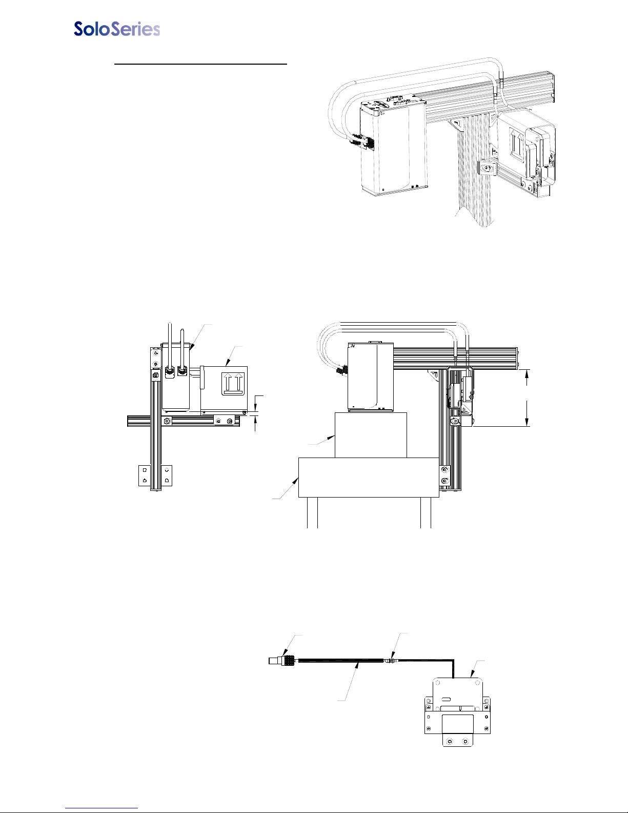
Thermal Jet Appendix K: Bulk Ink Supply
Print head
Regulator
Conve yor
Cart on b e ing p rin te d on
5-1/4"±1/2"
5/16"±1/2"
Regulator
Fitting, straight through,
1/8" barbs (5361-315)
Septum fitting
Tubing, 1/8" id x 1/4" od
(130 1- 46 8)
Setup for print down application
The bracketry that comes standard
with the print head does not accommodate a print down setup. A separate
bracket kit (5780-227) is available to
allow for a print down setup. This kit
includes tubing and fittings for extending the tubing between the regulator
and print head. If only the tubing and
fittings are needed then tubing kit
5780-211 can be used. This kit
includes enough tubing and fittings to
accommodate five half inch print heads
or two one inch print heads.
1. Mount the print head and regulator. The regulator must be positioned appropriately
in relation to the print head (see figure). If the regulator is positioned too high with
respect to the print head then ink may seep out of the print head. If this occurs simply lower the regulator until it is positioned properly.
2. It will be necessary to splice in a length of tubing between the regulator and print
5780-329 Operations Manual Rev J Page 64
head (see image below). This should be done before bleeding air out of the ink
lines.
Page 70
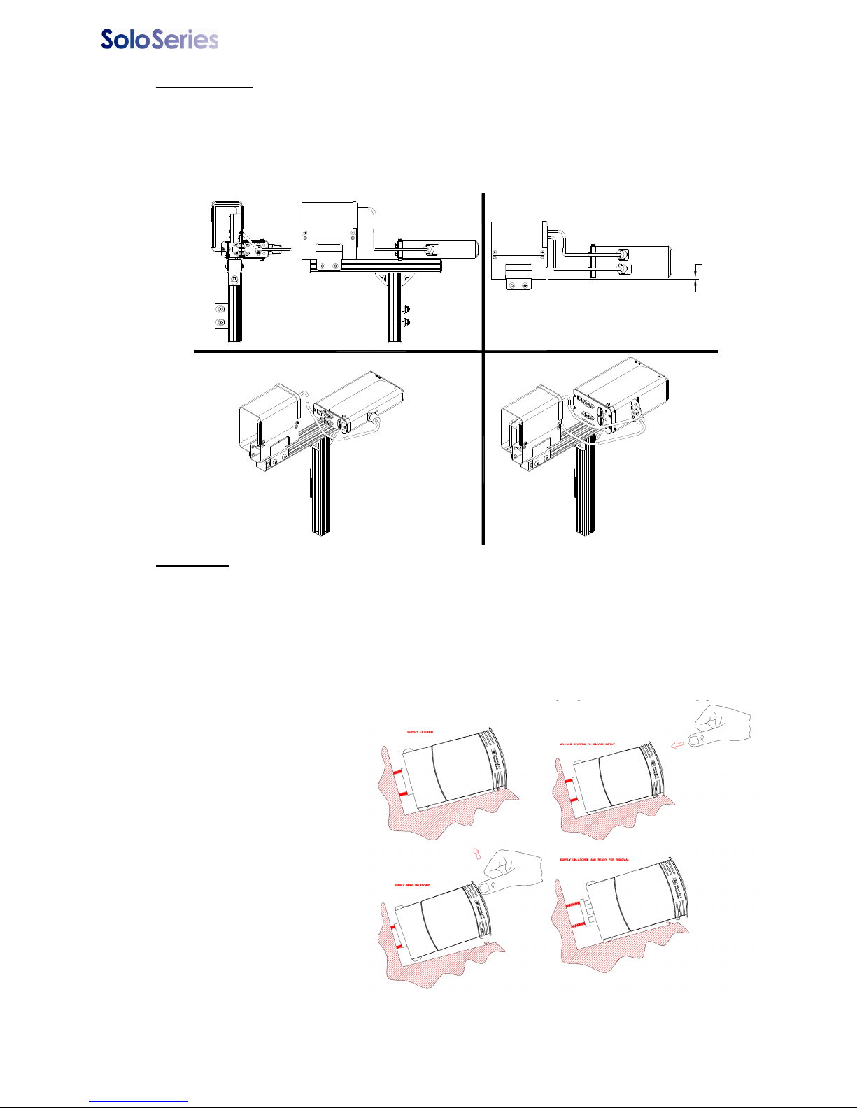
Thermal Jet Appendix K: Bulk Ink Supply
1/8 ± 1/4"
SoloSeries45 SoloSeries90
90° Tilt Setup
The bulk ink supply allows the print head to be tilted 90° from vertical versus the 45° limitation with a standard print cartridge. The relative positioning between the reservoir and print
head needs to be maintained for the print head to function properly. Standard bracketry
may be used to mount the print head in this orientation, however it may be necessary to
extend the tubing between the reservoir and print head (reference the print down setup for
instructions).
Operation
● Operating pressure of the bulk ink supply is 4-5 psi. Once pressure drops below 4 psi the air
pump will turn on and pressurize the ink supply up to 5 psi.
● If the pump can not achieve 5 psi after running for 15 seconds the system goes into an "Ink
Low" state (beacon will turn on solid) indicating the 350 ml ink cartridge is empty. The print
heads will continue to print because there is still ink in the print head cartridges; this allows
ample time to change the 350 ml ink cartridge.
● Changing the 350 ml bulk ink cartridge:
○ Press the pressure
relief valve on the
back of the bulk ink
system to depressurize the ink cartridge.
○ Push in and up
slightly on the cartridge to release it
from the holster.
○ Insert the new car-
tridge. The system
will detect the new
cartridge and begin
pressurizing automatically.
● Maximum print heads
per ink system: Four
1" print heads, eight
½" print heads, or any combination of the two totalling eight print cartridges.
5780-329 Operations Manual Rev J Page 65
Page 71

Thermal Jet Appendix K: Bulk Ink Supply
● A red LED on the rear panel of the SoloSeries IS, and an optional beacon, indicate the system’s operational status:
○ LED/beacon is off - system is operating normally.
○ LED/beacon is on steady - normal system operating pressure (5 psi) was not achieved
after 15 seconds of continuous pressure pump operation and the pump has shut down. It
indicates that the ink cartridge is empty and needs to be replaced. The pump will automatically restart when the cartridge is replaced or power is cycled off and on.
○ LED/beacon is blinking rapidly - the system has experienced a rapid loss of pressure,
possibly due to a break in an ink line, and has shut down.
○ The LED repeatedly blinks rapidly for one second, then goes out for one second, blinks
for one second, goes out for one second, etc.; the beacon continuously blinks rapidly with
no one second "off" periods - indicates a missing ink cartridge or the cartridge is not being
detected by the system.
5780-329 Operations Manual Rev J Page 66
 Loading...