


Operations
Manual
Handheld Controller
5780-346FX
Revision F
1 Missouri Research Park Drive * St. Charles, MO 63304 * 800-369-5384
Illinois Tool Works Inc. © 2009

Handheld Controller Table of Contents
TABLE OF CONTENTS
Section 1: Introduction ..................................................................................................................................3
Overview....................................................................................................................................................3
Keypad...................................................................................................................................................3
Display Elements...................................................................................................................................4
Section 2: Getting Started.............................................................................................................................6
Select the Unit of Measure ....................................................................................................................6
Adjusting the Display .............................................................................................................................6
The Status Screen.................................................................................................................................7
Configuring the Print Head(s)................................................................................................................8
Setting the Photocell Type, Print Speed, Print Direction, and Ink System............................................8
Synchronizing Multiple Print Heads to the Same Time and Date........................................................11
Section 3: Print Messages ..........................................................................................................................12
The Edit Screen...................................................................................................................................12
Edit Screen Menu Functions................................................................................................................12
Creating a Print Message........................................................................................................................13
Set the Message Properties ................................................................................................................13
Add the Print Fields..............................................................................................................................14
Select a Font........................................................................................................................................15
Set the Field Indent..............................................................................................................................15
Adding a Text Field..............................................................................................................................16
Adding a Date Code.............................................................................................................................17
Adding a Time Code............................................................................................................................18
Adding a Product Count.......................................................................................................................19
Saving, Retrieving, and Deleting Print Messages...................................................................................20
Saving a Message ...............................................................................................................................20
Retrieving a Message..........................................................................................................................20
Deleting a Message............................................................................................................. ................20
Printing a Message..................................................................................................................................21
The Print Screen..................................................................................................................................21
Print Screen Function Keys .................................................................................................................21
Printing a Message from Memory........................................................................................................22
5780-346FX Operations Manual Rev F Page 2 of 22
Handheld Controller Section 1: Introduction
Section 1: Introduction
This manual describes the operation of the Foxjet SoloSeries45 Handheld Controller as used to control
SoloSeries45 Thermal Jet print heads. The Handheld Controller can be used to individually operate from
one to four SoloSeries45 print heads hooked together in a daisy chain configuration: print head
configuration may be set or checked, print head status can be monitored, and print messages can be
created, edited, saved, retrieved and uploaded to the attached print head(s).
SoloSeries45 Thermal Jet print heads can operate stand-alone, so once they are set up and printing their
operation can be secured by disconnecting the Handheld Controller. This feature also allows multiple
SoloSeries45 print stations to be controlled using a single Controller. Simply carry the Handheld
Controller to the print station that needs attention, plug in, perform the desired task, unplug and move on
to the next print station.
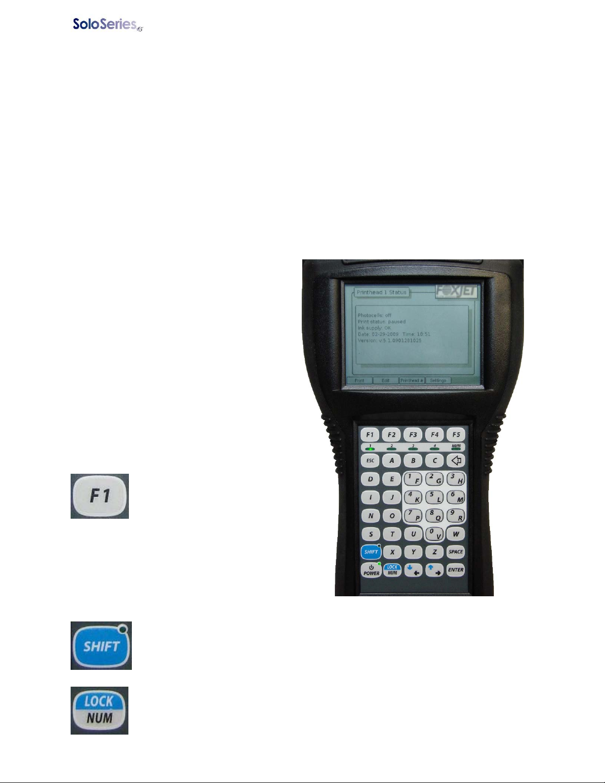
Overview
The SoloSeries45 Handheld Controller has a back
lit, 3.75” (95 mm) diagonal black and white
graphics display and a 40-key keypad (see
illustration, right).
LEDs on the keypad indicate Power On (upper
right corner of the POWER key), Shift Lock
(upper right corner of the SHIFT key), Num Lock
(NUM LED, right side of LED bar just below F5),
and which one of up to four possible print heads is
being addressed (LED bar, LEDs 1 – 4).
A brief summary of the keypad and display
operation follows. More detailed descriptions are
given elsewhere in this manual as required.
Keypad
Function Keys: Use the five
function keys (F1 – F5) at the top
of the keypad to navigate from
screen to screen and to select
options within a screen. Each
key’s function, which changes from screen to
screen, is displayed at the bottom of the screen
just above the key. When a function key has no
function its corresponding spot at the bottom of the
display is blank (see F5, right).
SHIFT Key: Press the SHIFT key for lower case letters; normal (un-shifted) ke ypad
operation produces upper case letters. The SHIFT key operates push on/push off: press
it once for shift mode, enter your lower case letters, then press it again to return to normal
keypad operation. An LED in the upper right corner of the SHIFT key lights when the
keypad is in the shift mode.
NUM LOCK Key: Press the NUM LOCK key to ac cess the numeric keypad. The NUM
LOCK key operates push on/push off: press it once for num lock mode, enter your
numbers, then press it again to return to normal keypad operation. The NUM LED
(located just under the F5 key) lights when the keypad is in the num lock mode.
5780-346FX Operations Manual Rev F Page 3 of 22
Handheld Controller Section 1: Introduction
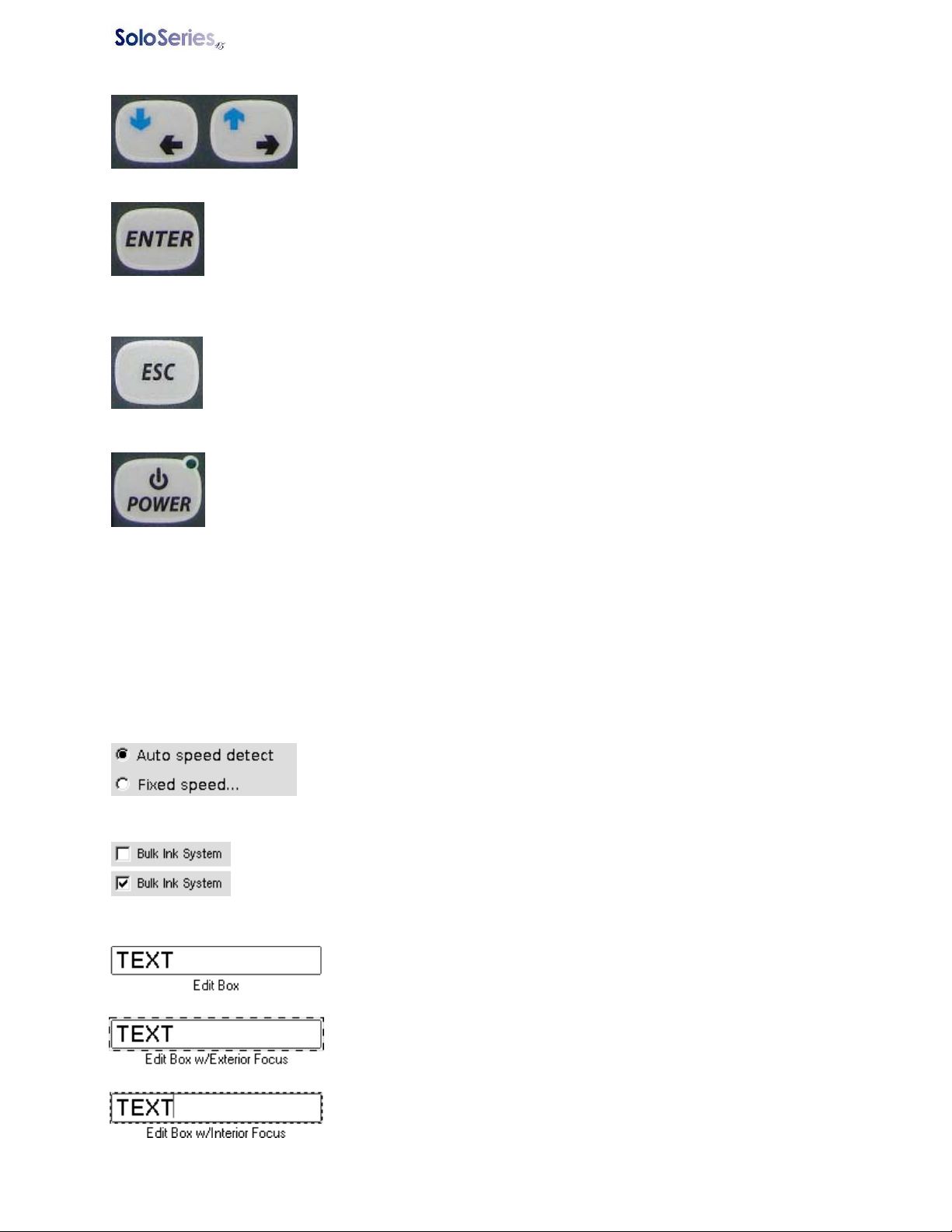
Arrow Keys: Use the arrow keys to move input focus from one screen
element to another, to move about within a screen element, and to move the
cursor while creating or editing a print message. The arrow keys can also
be used to stop from print head to print head on the Print and Status
screens.
ENTER Key: Use the ENTER key to move input focus into and out off a screen element.
For example, a screen has, among other elements, a list box, and using the arrow keys,
the list box is selected. Selecting the list box gives it input focus, but focus is only on the
exterior of the box, and if an arrow key is pressed input focus will move to another screen
element. To move input focus to the interior of the box press ENTER: now use the arrow
keys to select an item in the box. Press ENTER again to return focus to the exterior of the box.
ESC Key: The ESC (Escape) key functions as a limited “undo” key. For any entry box,
text or numeric, press ESC to undo any immediate changes made; for list boxes press
ESC to return to the first item on the list.
POWER Key: Press the POWER key to put the Controller into a low power sleep mode;
press it again to instantly resume operation with no loss of data.
NOTE: If power is removed while the Controller is in the sleep mode any unsaved data
will be lost.
Intelligent Operation: The number keys and the arrow keys feature intelligent operation: on screens
where numeric input is the only possible operation (entering a product count, for example) the keypad
automatically goes to NUM LOCK mode. Similarly, where up/down arrow key operation is the only choice
possible (scrolling through the items in a list box, for example), using the arrow keys un-shifted
automatically gives you up/down operation.
Display Elements
Check Box: Used to enable or disable an option or feature. A checkmark indicates
the option or feature is enabled, white space indicates it is disabled.
Radio Button: Used to indicate which option from a number of options is
the current selection. A black dot indicates the selected option, a white dot
an un-selected option. Auto speed detect is the selected option in the
picture at left.
Edit Box: Used to enter or edit text or numeric data. An edit box must
have input focus in order to enter or edit data.
An edit box has two types of input focus: exterior and interior. A large
dashed line around the box indicates exterior focus. When an edit box
has exterior focus, pressing an arrow key moves focus off the edit box
and onto the next screen element.
A small dashed line around the box indicates interior focus. When an
edit box has interior focus it is in the edit mode: data can be entered and
edited, and pressing the arrow keys moves the cursor left and right
through the data. Press ENTER to switch between exterior and interior
focus.
5780-346FX Operations Manual Rev F Page 4 of 22

Handheld Controller Section 1: Introduction
List Box: Used to select one item from a list of many.
A list box has two types of focus: exterior and interior. A large dashed line (see
Edit Box examples above left) around the box indicates exterior focus. When a
list box has exterior focus, pressing an arrow key moves focus off the list box and
onto the next screen element.
A small dashed line around the box indicates interior focus. When a list box has
interior focus, pressing the arrow keys moves the selection bar up and down
through the list.
Press ENTER to switch between exterior and interior focus.
5780-346FX Operations Manual Rev F Page 5 of 22
Handheld Controller Section 2: Getting Started
Section 2: Getting Started
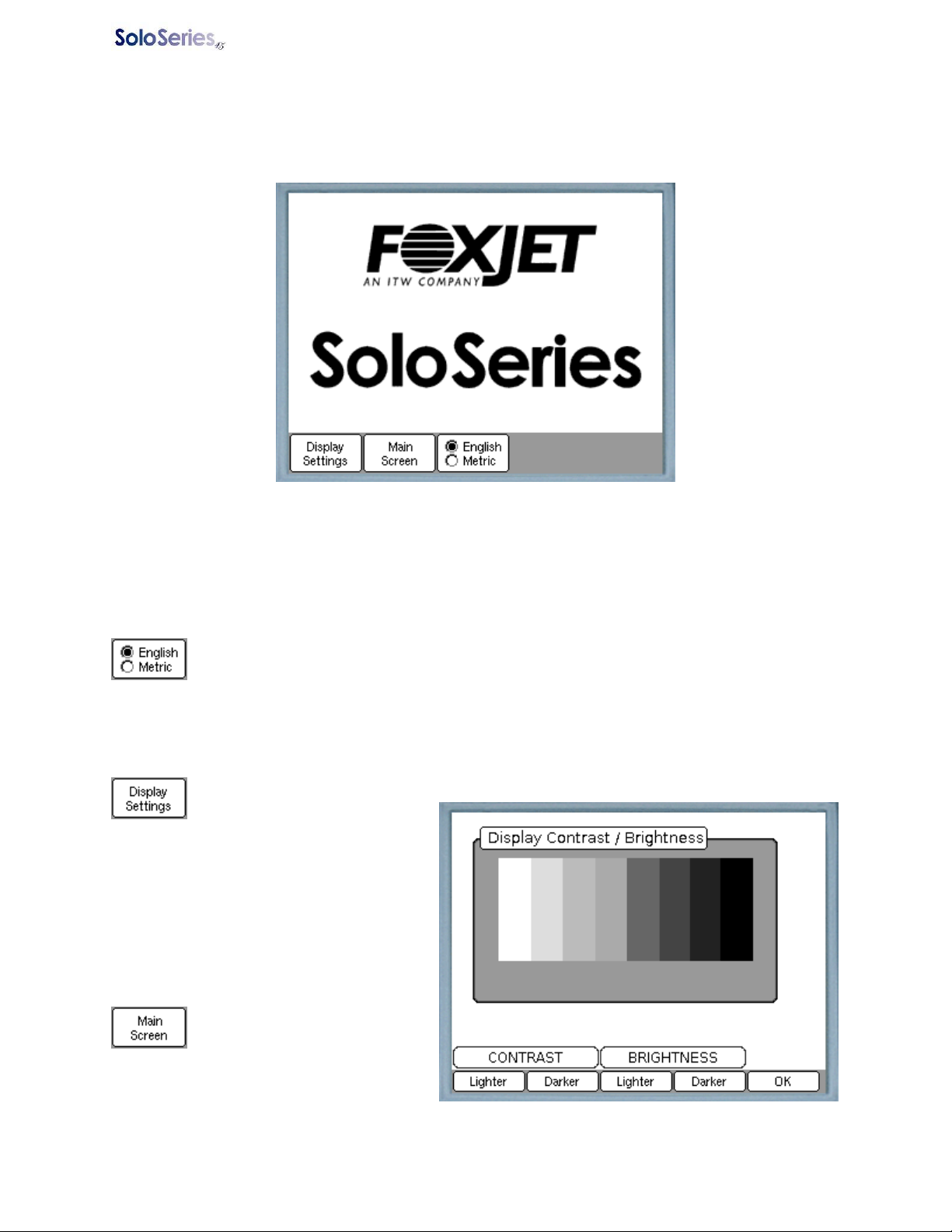
The Handheld Controller plugs into the left hand connector on the back of the SoloSeries45 pri nt head.
About twelve seconds after being plugged in the Startup Screen appears:
From the Startup Screen you can adjust the display’s contrast and backlight brightness, select the units of
measure used throughout the other screens, or proceed to the main operating screens. Once you exit
the Startup Screen you cannot return except by cycling power to the Handheld Controller.
Select the Unit of Measure
Press English / Metric (F3) to toggle between English (feet & inches) and Metric (meters &
centimeters) units of measure. Radio buttons show the current selection. The selection is
saved while the controller is turned off.
Adjusting the Display
Press LCD Contrast (F1) to
adjust the display’s contrast or
backlight brightness:
Adjust the contrast and brightness as
desired, and then press OK (F5). The
display settings are lost when the controller is
unplugged.
Press Main Screen (F2) to
proceed to the Print Screen.
The Print Screen is one of three
main operating screens; the other two are the
Edit Screen and the Status Screen. Any one
of the main screens is directly accessible
from the others.
5780-346FX Operations Manual Rev F Page 6 of 22
Handheld Controller Section 2: Getting Started
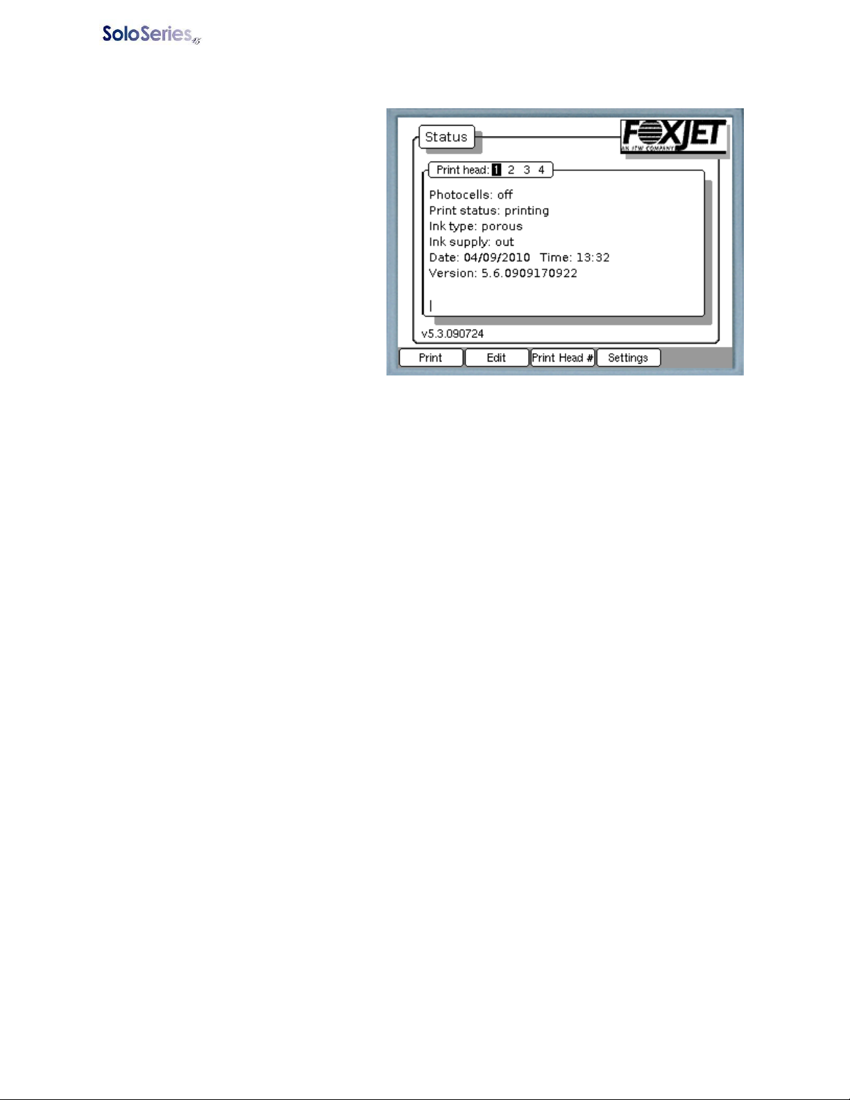
The Status Screen
The Status Screen displays the status of the
currently selected print head, and function
keys provide access to the Print Screen,
Edit Screen, Print Head Selection Screen,
and Print Head Setup Screens.
Print head status includes:
Print head: Indicates the current print head
selection. Use the left/right arrow keys to
sequence through the print heads, or go
directly to a particular print head by pressing
the 1 – 4 keys.
Photocells:
When a print head is configured to use its
internal photocells the status is reported as
- no response – the controller
received no photocell status information.
- off – neither photocell is blocked.
- left – the left photocell is blocked (as seen from the front of the print head).
- right – the right photocell is blocked (as seen from the front of the print head).
- both – both photocells are blocked.
When a print head is configured to use an external photocell the status is reported as
- no response – the controller received no photocell status information.
- off – the photocell is not blocked.
- on – the photocell is blocked.
Print status:
- printing – the print head is active. It will print when the photocell is blocked.
- paused – the print head is inactive. It will not print when the photocell is blocked.
Ink type:
- porous
- non-porous
- unknown – the controller received no ink type information, or the print head has a non-Diagraph
print cartridge.
Ink supply:
- no response – the controller received no ink supply status.
- OK – ink supply is between 100% and 10%
- low – ink supply is between 10% and 2%
- out – cartridge has less than 2% of ink supply remaining.
- stop print – ink supply unknown or print head is in thermal shutdown; printing stops.
Date: 2-digit month, 2-digit date, 4-digit year as reported by the clock in the print head.
Time: Hours and minutes as reported by the clock in the print head.
Version: Print head firmware version number. At the lower left corner of the display, just above the Print
and Edit buttons, is the Handheld Controller’s firmware version number.
5780-346FX Operations Manual Rev F Page 7 of 22

Handheld Controller Section 2: Getting Started
Configuring the Print Head(s)
The SoloSeries45 Handheld Controller operates from 1 to 4 print heads attached one to another in a
daisy chain configuration, but communicates with only one print head at a time. LEDs 1 to 4 on the LED
bar on the keypad indicate which print had is being addressed. Print head # 1 is always at the end of the
daisy chain farthest from the controller, then moving towards the controller, print heads # 2, # 3, and # 4.
The controller defaults to addressing print head # 1 at power up.
The print head being addressed may be changed from any screen that includes an
element similar to what is seen at left. On all but the Print Head Settings screen,
sequence through the print heads by pressing the left or right arrow key; to go directly to a particular print
head press the 1 – 4 buttons. To change print heads on the Print Head Settings screen press Select
Print Head (F1). (See below.)
To configure the print heads press Settings. The Settings button is F4 on the Status
Screen, and F3 on the Print Screen. When Settings is pressed the Settings menu replaces
the normal Status Screen or Print Screen menu at the bottom of the display:
Setting the Photocell Type, Print Speed, Print Direction, and Ink System
Press Print Head Settings (F2) to select the print head’s photocell type, method of
controlling print speed, and print direction:
The Print Head Settings Screen shows the current configuration for the selected print head.
Press Select Print Head (F1) to select the desired print head. It takes a few seconds for the
screen to update after changing print heads.
Press Select Photocell (F2) to toggle between the Internal and External photocell
selections. Radio buttons indicate the current selection. When External photocell is
selected a box appears for entering the photocell offset, which is the distance from the
center of the photocell to the center of the print head. The maximum offset is 99.0 inches (251.4 cm).
5780-346FX Operations Manual Rev F Page 8 of 22

Handheld Controller Section 2: Getting Started
Using an external photocell requires using either a fixed print speed or an external enco der, and a fixed
print direction.
Press Select Speed Control (F3) to sequence through the methods available for controlling
print speed: Auto speed detect, External encoder, and Fixed speed. The Auto speed
detect method, which uses the print head’s internal photocells to determine print speed, is
not available when using an external photocell. Radio buttons indicate the current section. When Fixed
speed is selected a box appears for entering the print speed. The maximum print speed is 200 ft/min
(60.9 m/min).
Press Select Print Direction (F4) to sequence through the available print direction choices
(see above): Auto detect, product travels right to left past the print head, and product
travels left to right past the print head. Auto detect, which uses the print head’s internal
photocells to determine print direction, is not available when using an external photocell. Radio buttons
indicate the current selection.
Press MORE (F5) to display page 2 of the menu:
Press Bulk Ink System (F2) to enable/disable bulk ink system operation in a print head. A
check mark in the box indicates bulk ink sy st em operation is enabled. Configuring a print
head for bulk ink system operation changes the method the print head uses to determine ink
low and ink out conditions. Enabling bulk ink system operation in a print head that is using a standard
print cartridge, and vice-versa, will cause incorrect ink level reporting.
Press OK (menu page 2, F4) when done to return to the Settings menu.
5780-346FX Operations Manual Rev F Page 9 of 22

Handheld Controller Section 2: Getting Started
Setting the Time and Date
Press Set Date/Time (F3 on the Setting menu) to display the current date and time as
reported by the selected print head’s internal clock:
Press Set Time (F3) to set the clock:
Press Hour (F2); enter the hour.
Press Minute (F3); enter the minute.
Press OK (F5) to set the selected print head’s clock, then return to the Date/Time Screen.
Press Cancel (F1) to return to the Date/Time Screen without changing the print head’s clock.
5780-346FX Operations Manual Rev F Page 10 of 22

Handheld Controller Section 2: Getting Started
Press Set Date (F4) to set the date:
Press Month (F2); enter the month.
Press Day (F2); enter the date.
Press Year (F4); enter the year.
Press OK (F5) to set the date on the selected print head and return to the Date/Time Screen.
Press Cancel (F1) to return to the Date/Time screen without changing the print head’s date.
Synchronizing Multiple Print Heads to the Same Time and Date
On the Date/Time Screen, press Synchronize (F5) to set all print heads in the daisy chain to
the same time and date as that of the print head currently being addressed.
Press Back (F1) to return to the Settings menu.
5780-346FX Operations Manual Rev F Page 11 of 22

Handheld Controller Section 3: Print Messages
Section 3: Print Messages
A print message, for purposes of using the Handheld Controller, is defined as all data printed by a single
SoloSeries45 Thermal Jet print head. A print message may contain up to 10 data fields, with each field
being fixed text, a date code, a time code, or a product count. Each field may be printed using a large
(½”) or small (¼”) Arial style font, and with the small font, two lines of data may be printed one atop the
other.
The Edit Screen
Print messages are created, edited, and saved on the Edit Screen. Open the Edit Screen from the Status
or Print Screen by pressing Edit (F2).
Dominating the central part of the Edit Screen are long text boxes for the input and display of the up to
ten data fields that make up a print message. To the right of each of the field data boxes are boxes for
displaying the field’s indent, or its distance from the product’s left edge, and a graphical representation of
the font used to print the field. Images used to represent the font are:
= Large (1/2”) font.
= Small (1/4”) font printed on the top line.
= Small font printed on the bottom line.
At the top left of the Edit Screen is the message name; at the top right is the product width.
Edit Screen Menu Functions
At the bottom of the page is the Edit Screen menu. The Edit Screen menu contains a total of ten items
spread over three pages. To scroll through the pages press MORE (F5). The entire Edit Screen menu is:
Print (F1): Go to the Print Screen. You will be prompted to save any changes.
Status (F2): Go to the Status Screen. You will be prompted to save any changes.
5780-346FX Operations Manual Rev F Page 12 of 22

Handheld Controller Section 3: Print Messages
New (F3): Create a new print message. All fields are cleared, and field and message properties are set
to their default values:
• The indent for field #1 is set to 0.00.
• The font for field #1 is set to Large.
• Product Width is set to 12.00 inches (30.48 cm).
• Repeat Print is set to Off
• Message name is set to Untitled.
File (F4): Save, open, and delete print message files.
Codes (Page 2, F1): Make a field a date, time, or count code.
Font (Page 2, F2): Select the current field’s font: Large, Small top line, or Small bottom line.
Indent (Page 2, F3): Set a field’s horizontal position by specifying its distance from the left edge of the
product.
Clear (Page 2, F4): Clear or erase the current field contents; indent is set to 0.00; font is set to Large.
Width (Page 3, F1): Specify the product width.
Repeat (Page 3, F2): Specify if the message is to print continually in web mode.
Creating a Print Message
Press Edit (F2) from the Print Screen or Status Screen.
Press New (F3) when asked if you want to create a new message or open an existing one.
Press MORE (F5) twice to go to the third page of the Edit Menu.
Set the Message Properties
Press Width (F1) to open the Product Width Screen:
Enter the product width; to enter a decimal point press F1 or the W key. For web printing applications
enter the print-to-print distance as the product width.
Press OK (F5) to return to the Edit Screen. Note that the product width box at the top right
of the display shows the product width just entered.
5780-346FX Operations Manual Rev F Page 13 of 22

Handheld Controller Section 3: Print Messages
If the message is for a web application press Repeat (F2) to open the Repeat Print Screen:
Press On (F1) to enable repeat print.
Press OK (F5) to return to the Edit Screen.
Add the Print Fields
There are three steps to adding a field to a print message: select the font, set the indent, and enter the
print data. The steps do not have to be performed in any particular order.
Use the up/down arrow keys to move from field to field.
PLEASE NOTE: In order for a message to print properly, print fields MUST be added in the order that
they appear in the print message, left to right, top to bottom. To make this easier, the editor prevents any
data from being entered into a field until the field before it contains data. Nothing can be entered into field
#2, for example, until field #1contains something. Also, as each field is entered, the minimum indent for
the next field is calculated and added to the display. This indent is the minimum required to prevent a
field from overlapping the field to its immediate left, and does not provide for any additional spacing
between fields. If a field is not to be butted up against the one to its left its indent will need to be set
larger than the minimum. See Set the Field Indent on page 15.
5780-346FX Operations Manual Rev F Page 14 of 22

Handheld Controller Section 3: Print Messages
Select a Font
Press Font (Page 2, F2) to display the Fonts Screen. An ‘X’ in the check box indicates the
current font selection.
Press Large (F1) to select the large font.
Press Small (F2) to select the small font, then…
Press Top (F3) to place the field on the top print line, or…
Press Bottom (F4) to place the field on the bottom print line.
Press OK (F5) to return to the Edit Screen.
Set the Field Indent
Press Indent (Page 2, F3) to display the
Indent Screen; the current indent setting is
shown in the edit box.
Enter the indent; to enter a decimal point
press F1 or the W key. The indent cannot be
made larger than the product width, or smaller
than the minimum indent shown just beneath
the edit box.
Press OK (F5) to return to the
Edit Screen.
While field indents cannot be made smaller than the calculated minimums, but it is possible, when editing
a field, to make the field longer than it previously was, or to move it to the right on the product, causing it
to overlap any field to its immediate right. When this occurs the indent box on the next field turns black.
See top of next page:
5780-346FX Operations Manual Rev F Page 15 of 22

Handheld Controller Section 3: Print Messages
The top figure on the left shows the message
before field #1 is edited; the bottom figure shows
it afterwards. The black indent box on field #2
indicates that the indent setting for that field is
now less than the minimum necessary to prevent
field overlap. To correct the error go to field #2
and press Indent to display the Indent Screen.
The new minimum indent is automatically put in
the edit box; change the indent to provide the
field separation desired and press OK (F5).
Adding a Text Field
To add a text field to a print message, go to the first blank field, press ENTER to put the edit box into the
edit mode, and enter the text. Press ENTER when done. A text field may have up to 52 characters,
including spaces.
Upper case letters, lower case letters, and numbers can be entered directly from the keypad.
Punctuation marks and other symbols are available via a symbol table. To access the symbol table the
edit box must be in the edit mode, which displays the edit mode menu:
Press Symbols (F1) to display the symbol table.
Use the arrow keys to select the desired symbol, and press ENTER to add the symbol to the text field and
return to the Edit Screen.
When editing a message, to change a date, time, or count field to a text field, first clear the field (press F4
on page 2 of the Edit Screen menu).
5780-346FX Operations Manual Rev F Page 16 of 22

Handheld Controller Section 3: Print Messages
Adding a Date Code
To add a date code to a print
message, go to the first blank
field and press Codes (Page 2, F1) to
display the Codes Menu:
Press Date (F3) to display the
Date Code Screen:
Use the arrow keys to select the desired date
format from the list.
If the date is to be offset (for a
best by date, sell by date, etc.)
press Date Offset (F3) and enter the number
of days for the offset.
Press OK (F5) to add the date
code to the print message and
return to the Edit Screen.
Press Cancel (F1) to return to
the Edit Screen without adding a
date code.
On the Edit Screen, a date code is displayed
as the date format chosen followed by the
date offset. See field #2, below.
5780-346FX Operations Manual Rev F Page 17 of 22

Handheld Controller Section 3: Print Messages
Adding a Time Code
To add a time code to a print
message, go to the first blank
field and press Codes (Page 2, F1) to
display the Codes Menu:
Press Time (F4) to display the
Time Code Screen:
Use the arrow keys to select the desired time
format from the list.
Press OK (F5) to add the time
code to the print message and
return to the Edit Screen.
Press Cancel (F1) to return to
the Edit Screen without adding a
time code.
On the Edit Screen, a time code is displayed
as the time format chosen. See field #3,
below.
5780-346FX Operations Manual Rev F Page 18 of 22

Handheld Controller Section 3: Print Messages
Adding a Product Count
To add an incrementing product
count to a print message, go to
the first blank field and press Codes (Page
2, F1) to display the Codes Menu:
Press Count (F4) to display the
Count Screen:
Enter the starting count. Use leading zeros
to specify the number of digits, up to a
maximum of 9. The count may start at any
value, but when it rolls over, it goes to 1.
Counts print with leading zeros.
Press OK (F5) to add the count
to the print message and return
to the Edit Screen.
Press Cancel (F1) to return to
the Edit Screen without adding
a count.
On the Edit Screen, a count field is
displayed as shown in field #4 below.
5780-346FX Operations Manual Rev F Page 19 of 22

Handheld Controller Section 3: Print Messages
Saving, Retrieving, and Deleting Print Messages
Press File (Page 1, F4) to open the File Screen and display a list of existing print messages.
Saving a Message
Press Edit Name (F2) to assign input focus to the Name box. Enter a file name for the print
message.
Press Save (F4) to save the message.
Press Back (F1) to return to the Edit Screen.
Retrieving a Message
Using the arrow keys, select the desired message from the list.
Press Open (F5) to open the file in the editor and return to the Edit Screen.
Deleting a Message
Using the arrow keys, select the desired message from the list.
Press Delete (F3) to delete the message.
Press Back (F1) to return to the Edit Screen.
5780-346FX Operations Manual Rev F Page 20 of 22

Handheld Controller Section 3: Print Messages
Printing a Message
Messages are sent to the print head(s) for printing from the Print Screen. The print screen also displays
what the currently selected print head is printing, as well as allows the operator to pause and resume
print.
The Print Screen
The Print Screen is accessible from either the Status or Edit screen by pressing Print (F1).
The information shown is retrieved from the print head so it may take a second or two for the screen to
update when it is first displayed or when switching from print head to print head. Information shown is
(left to right):
- The field number.
- The field’s contents. In the illustration above, field 1 is text, field 2 is a date code with a 180 day
offset, 3 is a product count, and 4 is text.
- The field’s indent.
- The field’s font. Fields 1 and 2 use the large font, field 3 uses the small font on the top line, and
field 4 uses the small font on the bottom line.
And along the top of the screen:
- The message’s file name.
- The currently selected print head.
- The current print status: Printing or Paused.
To select a different print head, use the left/right arrow keys to sequence through the heads, or go directly
to a particular print head by pressing 1 – 4. The print head currently being addressed is indicated by the
black square.
Print Screen Function Keys
Press Status (F1) to go to the Status Screen.
Press Edit (F2) to go to the Edit Screen.
Press Settings (F3) to display the Settings Menu.
Press File (F3) to open a print message file and send it to the currently selected print head
for printing.
Press Pause/Start Print (F5) to toggle print on and off. Press Pause Print to
stop print; press Start Print to resume print.
5780-346FX Operations Manual Rev F Page 21 of 22

Handheld Controller Section 3: Print Messages
Printing a Message from Memory
To print a message previously created and saved in memory:
On the Print Screen:
Press File (F3) to open the File Screen:
Use the arrow keys to select the desired message.
Press Print It (F5) to open the message, send the message to the print head for printing,
and return to the Print Screen.
Press Cancel (F1) to return to the Print Screen without opening a file or changing the print
message.
5780-346FX Operations Manual Rev F Page 22 of 22
 Loading...