

Foxjet Marksman MATRIX, Marksman ELITE User Manual

User
Manual
Marksman
MATRIX & ELITE
High Resolution Printing
for the Real World
2465-623
Revision E
1 Missouri Research Park Drive • St. Charles, MO 63304
Tel: 800-369-5384 • Fax: 636-300-2188
Illinois Tool Works Inc © 2018

www.foxjet.com
Marksman
MATRIX & ELITE
Ink Jet System
User Manual
2465-623
The information contained in this manual
is correct and accurate at the time of its
publication. ITW reserves the right to
change or alter any information or
technical specifications at any time and
without notice.
©2018 Illinois Tool Works Inc.
All rights reserved

Warranty:
The Marksman© Matrix & Elite Ink Jet system, including all components unless other
wise specified, carries a limited warranty.
The inks and conditioners used with the Marksman© Matrix & Elite Ink Jet system
carry a limited warranty.
For all warranty terms and conditions, contact the Distributor for a complete copy of the
Limited Warranty Statement.

Marksman Matrix & Elite
Section 1: Introduction . . . . . . . . . . . . . . . . . . . . . . . . . . . . . . . . . . . . . . . . . . . . . . . . . . . . . . . . . . . . 1
Section 2: Safety . . . . . . . . . . . . . . . . . . . . . . . . . . . . . . . . . . . . . . . . . . . . . . . . . . . . . . . . . . . . . . . . . . 2
Section 3: System Components . . . . . . . . . . . . . . . . . . . . . . . . . . . . . . . . . . . . . . . . . . . . . . . . . . . . . 3
Integrated Print Head . . . . . . . . . . . . . . . . . . . . . . . . . . . . . . . . . . . . . . . . . . . . . . . . . . . . . . . . . 5
Bracketry . . . . . . . . . . . . . . . . . . . . . . . . . . . . . . . . . . . . . . . . . . . . . . . . . . . . . . . . . . . . . . . . . .6
Photosensor . . . . . . . . . . . . . . . . . . . . . . . . . . . . . . . . . . . . . . . . . . . . . . . . . . . . . . . . . . . . . . . . 7
Encoder . . . . . . . . . . . . . . . . . . . . . . . . . . . . . . . . . . . . . . . . . . . . . . . . . . . . . . . . . . . . . . . . . . . 7
Inks . . . . . . . . . . . . . . . . . . . . . . . . . . . . . . . . . . . . . . . . . . . . . . . . . . . . . . . . . . . . . . . . . . . . . . 7
Waste Bottle . . . . . . . . . . . . . . . . . . . . . . . . . . . . . . . . . . . . . . . . . . . . . . . . . . . . . . . . . . . . . . . 7
Section 4: Installation . . . . . . . . . . . . . . . . . . . . . . . . . . . . . . . . . . . . . . . . . . . . . . . . . . . . . . . . . . . . . 8
Materials Required for Installation . . . . . . . . . . . . . . . . . . . . . . . . . . . . . . . . . . . . . . . . . . . . . . 8
System Installation Overview . . . . . . . . . . . . . . . . . . . . . . . . . . . . . . . . . . . . . . . . . . . . . . . . . . 9
Installing Bracketry . . . . . . . . . . . . . . . . . . . . . . . . . . . . . . . . . . . . . . . . . . . . . . . . . . . . . . . . . . 9
Mounting the Print System . . . . . . . . . . . . . . . . . . . . . . . . . . . . . . . . . . . . . . . . . . . . . . . . . . . 10
Setting Up the Print Head . . . . . . . . . . . . . . . . . . . . . . . . . . . . . . . . . . . . . . . . . . . . . . . . . . . . 11
Mounting the Photosensor . . . . . . . . . . . . . . . . . . . . . . . . . . . . . . . . . . . . . . . . . . . . . . . . . . . . 11
Ship Caps . . . . . . . . . . . . . . . . . . . . . . . . . . . . . . . . . . . . . . . . . . . . . . . . . . . . . . . . . . . . . . . . . 12
The Encoder . . . . . . . . . . . . . . . . . . . . . . . . . . . . . . . . . . . . . . . . . . . . . . . . . . . . . . . . . . . . . . . 13
Electrical Cable Connections . . . . . . . . . . . . . . . . . . . . . . . . . . . . . . . . . . . . . . . . . . . . . . . . .14
Priming the Print Heads . . . . . . . . . . . . . . . . . . . . . . . . . . . . . . . . . . . . . . . . . . . . . . . . . . . . . . 16
Section 5: Getting Started . . . . . . . . . . . . . . . . . . . . . . . . . . . . . . . . . . . . . . . . . . . . . . . . . . . . . . . . . 19
Counts . . . . . . . . . . . . . . . . . . . . . . . . . . . . . . . . . . . . . . . . . . . . . . . . . . . . . . . . . . . . . . . . . . . 23
User Data . . . . . . . . . . . . . . . . . . . . . . . . . . . . . . . . . . . . . . . . . . . . . . . . . . . . . . . . . . . . . . . . . 23
Configure, Print Head: . . . . . . . . . . . . . . . . . . . . . . . . . . . . . . . . . . . . . . . . . . . . . . . . . . . . . . . 25
Configure, System . . . . . . . . . . . . . . . . . . . . . . . . . . . . . . . . . . . . . . . . . . . . . . . . . . . . . . . . . . 28
Reports . . . . . . . . . . . . . . . . . . . . . . . . . . . . . . . . . . . . . . . . . . . . . . . . . . . . . . . . . . . . . . . . . . . 32
Delays . . . . . . . . . . . . . . . . . . . . . . . . . . . . . . . . . . . . . . . . . . . . . . . . . . . . . . . . . . . . . . . . . . . 33
Section 6: BoxWriter© Matrix & Elite Editor . . . . . . . . . . . . . . . . . . . . . . . . . . . . . . . . . . . . . . . . 34
Define . . . . . . . . . . . . . . . . . . . . . . . . . . . . . . . . . . . . . . . . . . . . . . . . . . . . . . . . . . . . . . . . . . . 34
Tools . . . . . . . . . . . . . . . . . . . . . . . . . . . . . . . . . . . . . . . . . . . . . . . . . . . . . . . . . . . . . . . . . . . . 47
Files . . . . . . . . . . . . . . . . . . . . . . . . . . . . . . . . . . . . . . . . . . . . . . . . . . . . . . . . . . . . . . . . . . . . .47
Elements . . . . . . . . . . . . . . . . . . . . . . . . . . . . . . . . . . . . . . . . . . . . . . . . . . . . . . . . . . . . . . . . . 56
ToolBar . . . . . . . . . . . . . . . . . . . . . . . . . . . . . . . . . . . . . . . . . . . . . . . . . . . . . . . . . . . . . . . . . . 69
Perspective . . . . . . . . . . . . . . . . . . . . . . . . . . . . . . . . . . . . . . . . . . . . . . . . . . . . . . . . . . . . . . . . 79
Section 7: Maintenance . . . . . . . . . . . . . . . . . . . . . . . . . . . . . . . . . . . . . . . . . . . . . . . . . . . . . . . . . . . 81
APS - Automatic Priming System . . . . . . . . . . . . . . . . . . . . . . . . . . . . . . . . . . . . . . . . . . . . . . 81
Shutdown Procedures . . . . . . . . . . . . . . . . . . . . . . . . . . . . . . . . . . . . . . . . . . . . . . . . . . . . . . . 82
Ink Storage . . . . . . . . . . . . . . . . . . . . . . . . . . . . . . . . . . . . . . . . . . . . . . . . . . . . . . . . . . . . . . . . 84
Section 8: Troubleshooting . . . . . . . . . . . . . . . . . . . . . . . . . . . . . . . . . . . . . . . . . . . . . . . . . . . . . . . . 85
Troubleshooting Notes . . . . . . . . . . . . . . . . . . . . . . . . . . . . . . . . . . . . . . . . . . . . . . . . . . . . . .85
Troubleshooting Tests . . . . . . . . . . . . . . . . . . . . . . . . . . . . . . . . . . . . . . . . . . . . . . . . . . . . . . . 86
Print Quality Troubleshooting . . . . . . . . . . . . . . . . . . . . . . . . . . . . . . . . . . . . . . . . . . . . . . . . .87
2465-623 User Manual Rev E

Marksman Matrix & Elite
Appendix A: Specifications . . . . . . . . . . . . . . . . . . . . . . . . . . . . . . . . . . . . . . . . . . . . . . . . . . . . . . . . 90
Matrix Controller Specifications . . . . . . . . . . . . . . . . . . . . . . . . . . . . . . . . . . . . . . . . . . . . . . 90
Elite Controller Specifications . . . . . . . . . . . . . . . . . . . . . . . . . . . . . . . . . . . . . . . . . . . . . . . . 91
Print Head Specifications . . . . . . . . . . . . . . . . . . . . . . . . . . . . . . . . . . . . . . . . . . . . . . . . . . . . 92
Appendix B: Theory of Operation . . . . . . . . . . . . . . . . . . . . . . . . . . . . . . . . . . . . . . . . . . . . . . . . . . 94
The Marksman© Matrix & Elite . . . . . . . . . . . . . . . . . . . . . . . . . . . . . . . . . . . . . . . . . . . . . . . 94
Print Heads . . . . . . . . . . . . . . . . . . . . . . . . . . . . . . . . . . . . . . . . . . . . . . . . . . . . . . . . . . . . . . .94
Photosensor . . . . . . . . . . . . . . . . . . . . . . . . . . . . . . . . . . . . . . . . . . . . . . . . . . . . . . . . . . . . . . . 94
Encoder . . . . . . . . . . . . . . . . . . . . . . . . . . . . . . . . . . . . . . . . . . . . . . . . . . . . . . . . . . . . . . . . . . 94
Matrix Wiring Diagram . . . . . . . . . . . . . . . . . . . . . . . . . . . . . . . . . . . . . . . . . . . . . . . . . . . . . . 95
Elite Wiring Diagram . . . . . . . . . . . . . . . . . . . . . . . . . . . . . . . . . . . . . . . . . . . . . . . . . . . . . . . 96
Appendix C: Parts and Supplies . . . . . . . . . . . . . . . . . . . . . . . . . . . . . . . . . . . . . . . . . . . . . . . . . . . 97
Consumables . . . . . . . . . . . . . . . . . . . . . . . . . . . . . . . . . . . . . . . . . . . . . . . . . . . . . . . . . . . . . . 97
Matrix Spare Parts Kits . . . . . . . . . . . . . . . . . . . . . . . . . . . . . . . . . . . . . . . . . . . . . . . . . . . . . . 97
Elite Spare Parts Kits . . . . . . . . . . . . . . . . . . . . . . . . . . . . . . . . . . . . . . . . . . . . . . . . . . . . . . . . 97
Accessories . . . . . . . . . . . . . . . . . . . . . . . . . . . . . . . . . . . . . . . . . . . . . . . . . . . . . . . . . . . . . . . 97
384e and 768e Print System Service Kit . . . . . . . . . . . . . . . . . . . . . . . . . . . . . . . . . . . . . . . . . 98
Appendix D: Testing the Electrical Outlet . . . . . . . . . . . . . . . . . . . . . . . . . . . . . . . . . . . . . . . . . . . 99
Electrical Line Transients . . . . . . . . . . . . . . . . . . . . . . . . . . . . . . . . . . . . . . . . . . . . . . . . . . . . 99
Appendix E: Database Start . . . . . . . . . . . . . . . . . . . . . . . . . . . . . . . . . . . . . . . . . . . . . . . . . . . . . . 100
Description . . . . . . . . . . . . . . . . . . . . . . . . . . . . . . . . . . . . . . . . . . . . . . . . . . . . . . . . . . . . . . 100
Database Start Task Routine Flowchart . . . . . . . . . . . . . . . . . . . . . . . . . . . . . . . . . . . . . . . . 100
Database Lookup Definition - Global Setting . . . . . . . . . . . . . . . . . . . . . . . . . . . . . . . . . . . . 101
Database Start Task . . . . . . . . . . . . . . . . . . . . . . . . . . . . . . . . . . . . . . . . . . . . . . . . . . . . . . . . 102
Serial Port Modification . . . . . . . . . . . . . . . . . . . . . . . . . . . . . . . . . . . . . . . . . . . . . . . . . . . . 102
Printer Report Modification . . . . . . . . . . . . . . . . . . . . . . . . . . . . . . . . . . . . . . . . . . . . . . . . . 103
Appendix F: Hand Scanner . . . . . . . . . . . . . . . . . . . . . . . . . . . . . . . . . . . . . . . . . . . . . . . . . . . . . . 104
Scan and Shoot Setup . . . . . . . . . . . . . . . . . . . . . . . . . . . . . . . . . . . . . . . . . . . . . . . . . . . . . . 104
Scanner . . . . . . . . . . . . . . . . . . . . . . . . . . . . . . . . . . . . . . . . . . . . . . . . . . . . . . . . . . . . . . . . . 105
Appendix G: Fonts . . . . . . . . . . . . . . . . . . . . . . . . . . . . . . . . . . . . . . . . . . . . . . . . . . . . . . . . . . . . . 107
Font List . . . . . . . . . . . . . . . . . . . . . . . . . . . . . . . . . . . . . . . . . . . . . . . . . . . . . . . . . . . . . . . . . 107
Font Samples . . . . . . . . . . . . . . . . . . . . . . . . . . . . . . . . . . . . . . . . . . . . . . . . . . . . . . . . . . . . . 108
Appendix H: Standard Operating Procedures . . . . . . . . . . . . . . . . . . . . . . . . . . . . . . . . . . . . . . . 113
FJSOP1 - Removal of FoxJet High Resolution Printheads . . . . . . . . . . . . . . . . . . . . . . . . . . 113
FJSOP2 - Daily Maintenance for AMS/APS Printheads . . . . . . . . . . . . . . . . . . . . . . . . . . . 115
FJSOP4 - Installation of FoxJet High Resolution AMS/APS Printheads . . . . . . . . . . . . . . .117
2465-623 User Manual Rev E

Marksman Matrix & Elite
Section 1: Introduction
The Marksman© Matrix & Elite are advanced high-resolution ink jet controllers that runs on
a Microsoft Windows 7® platform. It includes a built-in keypad with a TFT display with
touch-screen control. The Marksman© Matrix & Elite can control up to 4 Pro Series highresolution print heads for printing industry compliant barcodes, graphics or alphanumeric
text on porous materials and cases.
This manual covers the operation of the Marksman© Matrix & Elite Ink Jet Printing System,
Marksman© Matrix & Elite Controller and Print Heads.
Section 1: Introduction
2465-623 User Manual Rev E Page 1
Marksman Matrix & Elite
Section 2: Safety
Following is a list of safety symbols and their meanings, which will be found throughout this
manual. Pay attention to these symbols where they appear in the manual.
Wear safety goggles when performing the procedure described!
Caution or Warning! Denotes possible personal injury and/or damage to the equip-
!
ment.
Caution or Warning! Denotes possible personal injury and/or equipment damage
due to electrical hazard.
NOTE: (Will be followed by a brief comment or explanation.)
Section 2: Safety
Only trained personnel should operate and service the equipment.
NOTE: It is extremely important to:
• Clean up all ink spills with the appropriate conditioners immediately and dispose of all
waste according to local and state regulations.
• Wear safety glasses and protective clothing, including gloves, when handling all inks
and conditioners.
• Store inks and conditioners under the recommended conditions found on the MSDS
(Material Safety Data Sheet).
PRODUCT COMPLIANCE DISCLAIMER NOTE:
This product meets the requirements of CAN/CSA-22.2 NO.60950-00 * UL 60950 using
FoxJet an ITW Company approved items. Units are only tested and qualified with FoxJet
an ITW Company approved inks, parts and accessories. Use of other inks, parts or accessories may introduce potential risks that FoxJet an ITW Company can assume no liability
for.
2465-623 User Manual Rev E Page 2
Marksman Matrix & Elite
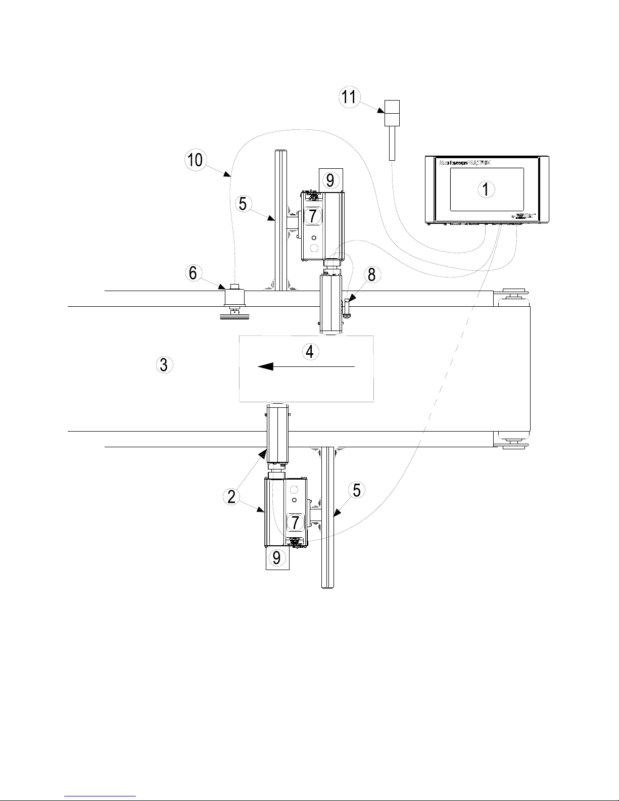
Section 3: System Components
1 Controller, Matrix or Elite
2 Proseries Print Head
3 Conveyor
4 Product
5 Print System Bracketry
6 Encoder
7 Ink Supply
8 Photo Sensor
9 Vacuum Waste Collector Bottle
10 Encoder Cable
11 Alarm Beacon (Strobe)
Section 3: System Components
2465-623 User Manual Rev E Page 3

Section 3: System Components
Marksman Matrix & Elite
The Marksman© Ink Jet System is available with the following components, options and
service kits:
Part Number
2464076 ProSeries 384e
2464076F ProSeries 384e, Flushed
2464078 ProSeries 384e, 90°
2464078F ProSeries 384e, 90°, Flushed
2464079 ProSeries 384e, Modular
2464079F ProSeries 384e, Modular, Flushed
2464082 ProSeries 768e
2464082F ProSeries 768e, Flushed
2464083 ProSeries 768e, Modular
2464083F ProSeries 768e, Modular, Flushed
2464084 ProSeries 768e, 90 Degree
2464084F ProSeries 768e, 90 Degree, Flushed
2465006D2 Controller Assembly, Marksman© Matrix, 2 Head, Domestic
2465006E2 Controller Assembly, Marksman© Matrix, 2 Head, European
2465006D4 Controller Assembly, Marksman© Matrix, 4 Head, Domestic
2465006E4 Controller Assembly, Marksman© Matrix, 4 Head, European
2465004D2 Controller Assembly, Marksman© Elite, 2 Head, Domestic
2465004E2 Controller Assembly, Marksman© Elite, 2 Head, European
Description
Print Head
Matrix Controller Assembly
Elite Controller Assembly
Remote PHC Board & Elite board kit
2465321 Assembly, Marksman remote PHC Board
2465246 Elite PHC Board Kit
Print Head/Controller Bracketry
2464550 Print Head Conveyor Mount Bracket
2464553 Print Head Pivot Bracket
2464561 X-Y Axis Linear Adjustment, Tool-Less Bracket
2464562 Conveyor Mount/Roller Bracket for 768 Print Head
2464563 Print Head Floor Mount Bracket Kit
2464564 Conveyor Mount/Roller Bracket for 384/352 Print Head
2464565 Conveyor Mounting Bracket with Integrated Guide Rails for 384/768 Print Head
2465243 Kit, T-Stand, Matrix & Elite
2465244 Kit, Conveyor Mounting, Matrix & Elite
2465254 Kit, Pivot Bracket, Matrix & Elite
Encoder, Photosensor, Alarm Beacon
2465224 Photosensor, ProSeries
2465253 Alarm Beacon (Strobe), 3-Color
2465525 Photosensor, Auxiliary, APS Controller
2465-623 User Manual Rev E Page 4

Section 3: System Components
Marksman Matrix & Elite
INK SYSTEM
WASTE BOTTLE
PRINT HEAD
INK BOTTLE
Cabling
2464182-010 Cable, Straight Thru, DB9, 10 Ft.
2464182-025 Cable, Straight Thru, DB9, 25Ft.
2464182-050 Cable, Straight Thru, DB9, 50 Ft.
2465155-002 Cable Kit, Print Head, DB25, 2 Ft.
2465155-010 Cable Kit, Print Head, DB25, 10 Ft.
2465155-025 Cable Kit, Print Head, DB25, 25 Ft.
2464312 Cable, APS Photocell Network ("Y" Cable for sharing Auxiliary Photocell)
Integrated Print Head
2465-623 User Manual Rev E Page 5
Section 3: System Components
Marksman Matrix & Elite
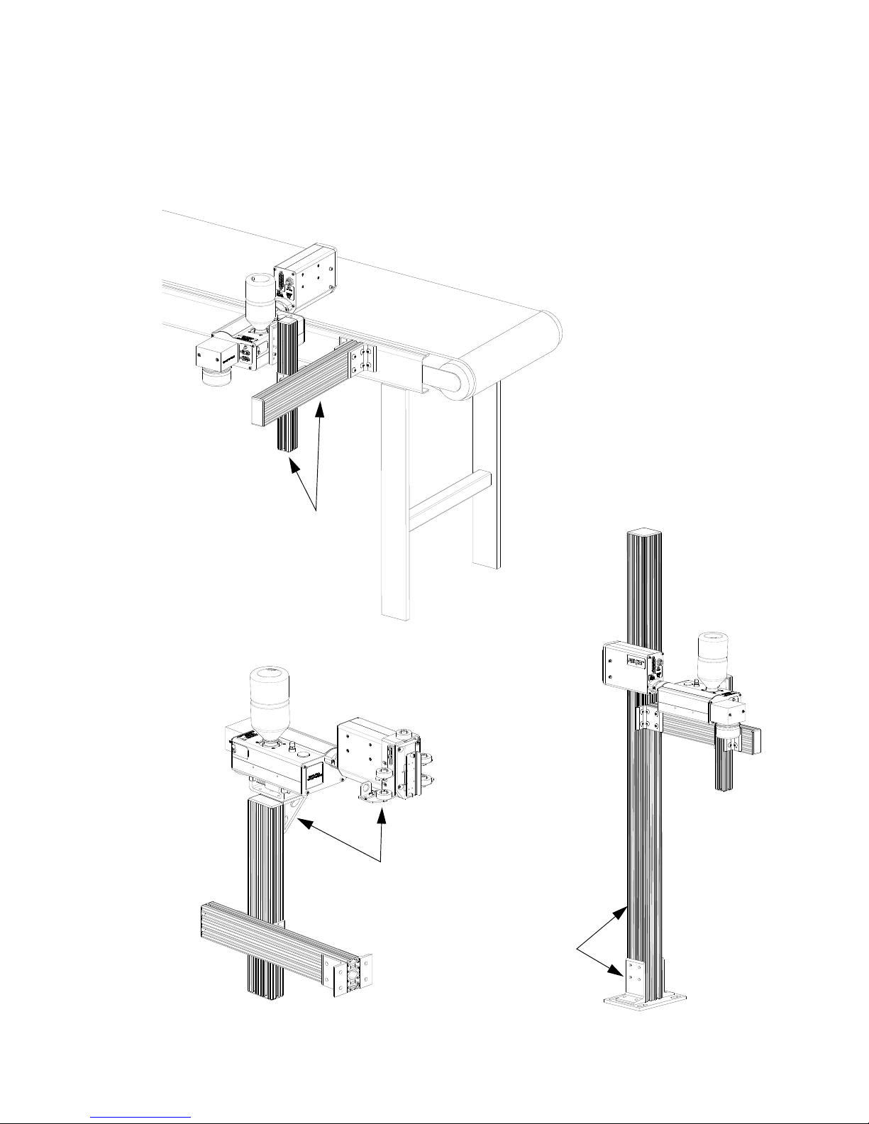
Retracting Bracket
Floor Mount
Conveyor Mount
Bracketry
Bracketry is the structure that supports the controller, print system and other accessories.
This manual details instructions for mounting all system components to a conveyor. Other
mounting options for the controller and print system include the floor mount and the retracting bracket. Assembly instructions are included with parts kits.
2465-623 User Manual Rev E Page 6
Section 3: System Components
Marksman Matrix & Elite
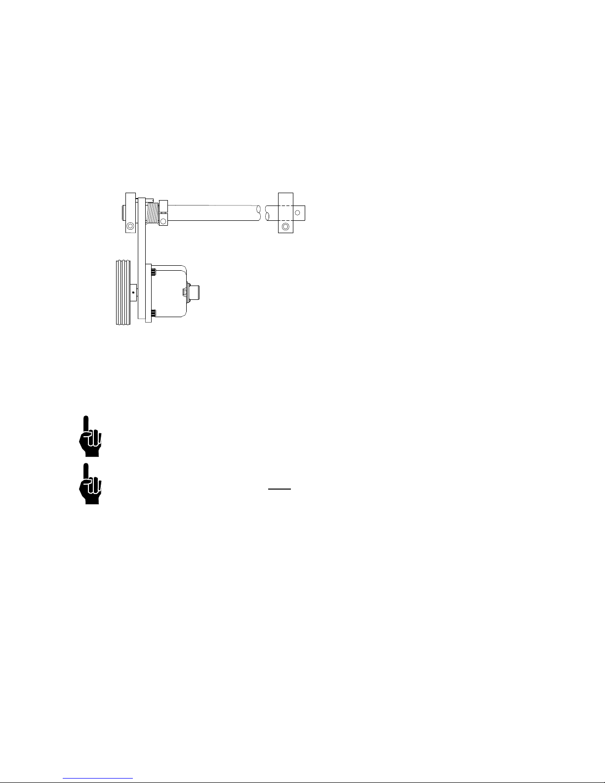
ENCODER ASSEMBLY
Photosensor
The photosensor is both a light source and a sensor. It emits light and detects the arrival of
a product when the product reflects the light source back to the sensor. The sensor then
sends a signal to the controller to start the printing cycle.
Encoder
The encoder assembly provides conveyor line
speed information to the controller. It also allows
automatic disabling of printing when the line
stops.
The Marksman© Matrix & Elite System uses a
5000 ppr open collector output encoder. The
wheel is sized to provide the correct timing
inputs to allow the print heads to print from 150
to 300 dpi.
Inks
Ink is supplied via 500 mL plastic containers. ScanTrue® II PLUS is a pigmented ink formulated for use on porous substrates.
NOTE: Check the label on the Print Head for correct ink type.
NOTE: Inks are not miscible. Do NOT
mix the inks.
Waste Bottle
The APS includes a Waste Collection Bottle mounted on the rear of the Print Head assembly. This bottle must be changed when full to prevent improper operation of the system.
Instructions for waste disposal are on the collection bottle.
2465-623 User Manual Rev E Page 7
Marksman Matrix & Elite
Section 4: Installation
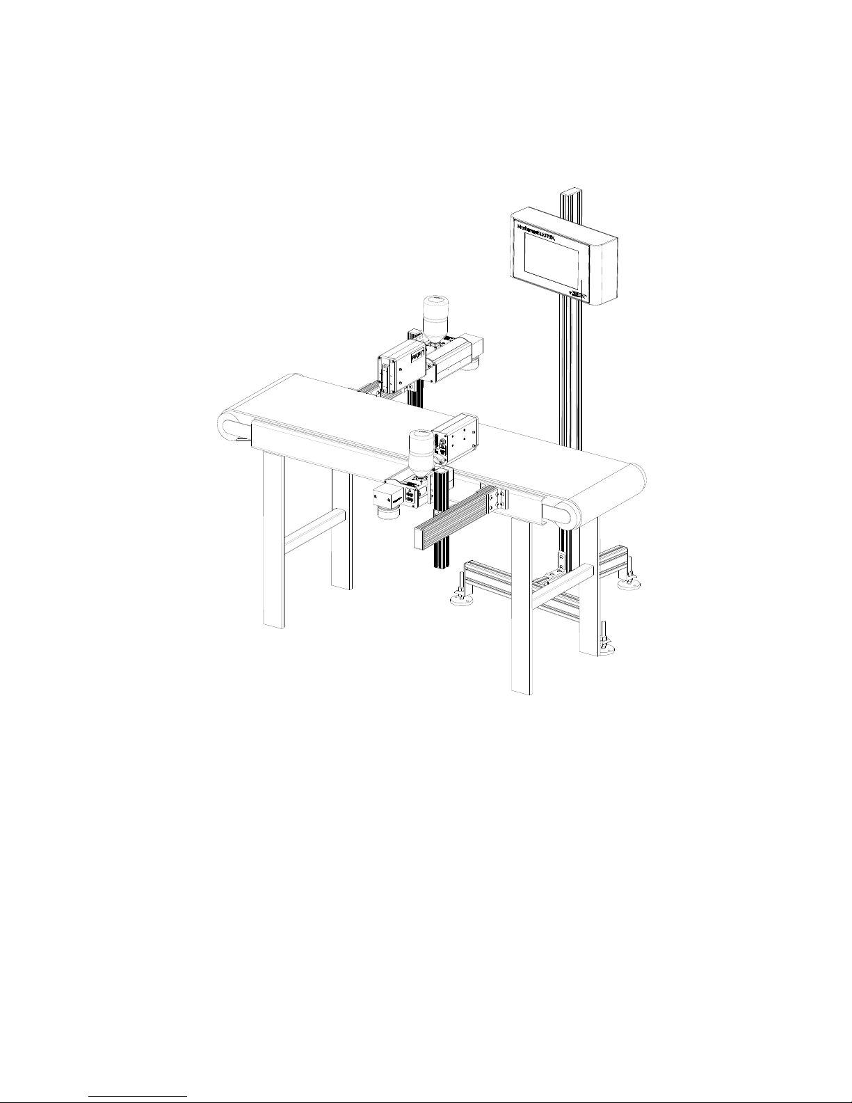
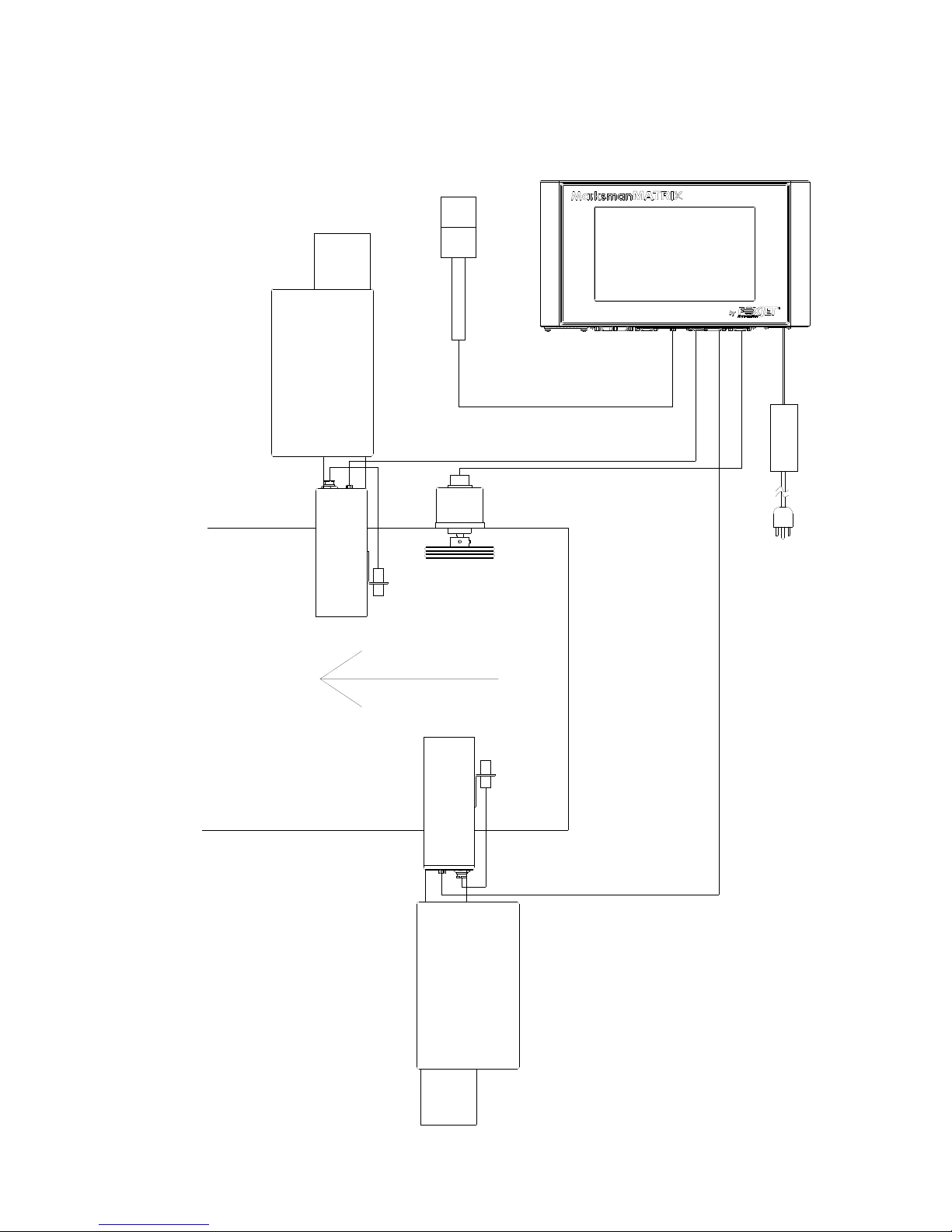
The figure below illustrates a typical conveyor-mounted installation. (Cables are not
shown.)
Section 4: Installation
Materials Required for Installation
You will need the following items:
• Lint-free wipes
• Safety goggles
•Level
• Tape measure
Use appropriate safety equipment and procedures. Leave print heads in their shipping cartons until all bracketry is in place and tightened down.
2465-623 User Manual Rev E Page 8
Section 4: Installation
Marksman Matrix & Elite
ATTACH ING
CORNER
BRACKET
Single T-nut
Corner Bracket
System Installation Overview
NOTE: The following steps give an overview of the procedure to properly install the Marks-
man© Matrix or Elite print system. Refer to the appropriate section for details.
1. Carefully plan the mounting location of the equipment. Keep in mind bracketry hardware location and printer equipment size.
2. Remove equipment from packaging.
3. Assemble all bracketry to the floor, conveyor, or other bracketry per bracketry installation section.
4. Mount the print system to its appropriate bracketry. Do not connect to power outlet.
5. Assemble the optional retracting bracket to each print head, if applicable.
6. Mount the print head(s) to their appropriate bracketry and in the approximate location
relative to the carton.
7. Mount the photosensor, optional bracketry, and optional encoder per procedure.
CAUTION: Remove the print head Ship Cap prior to operating the Print Heads.
!
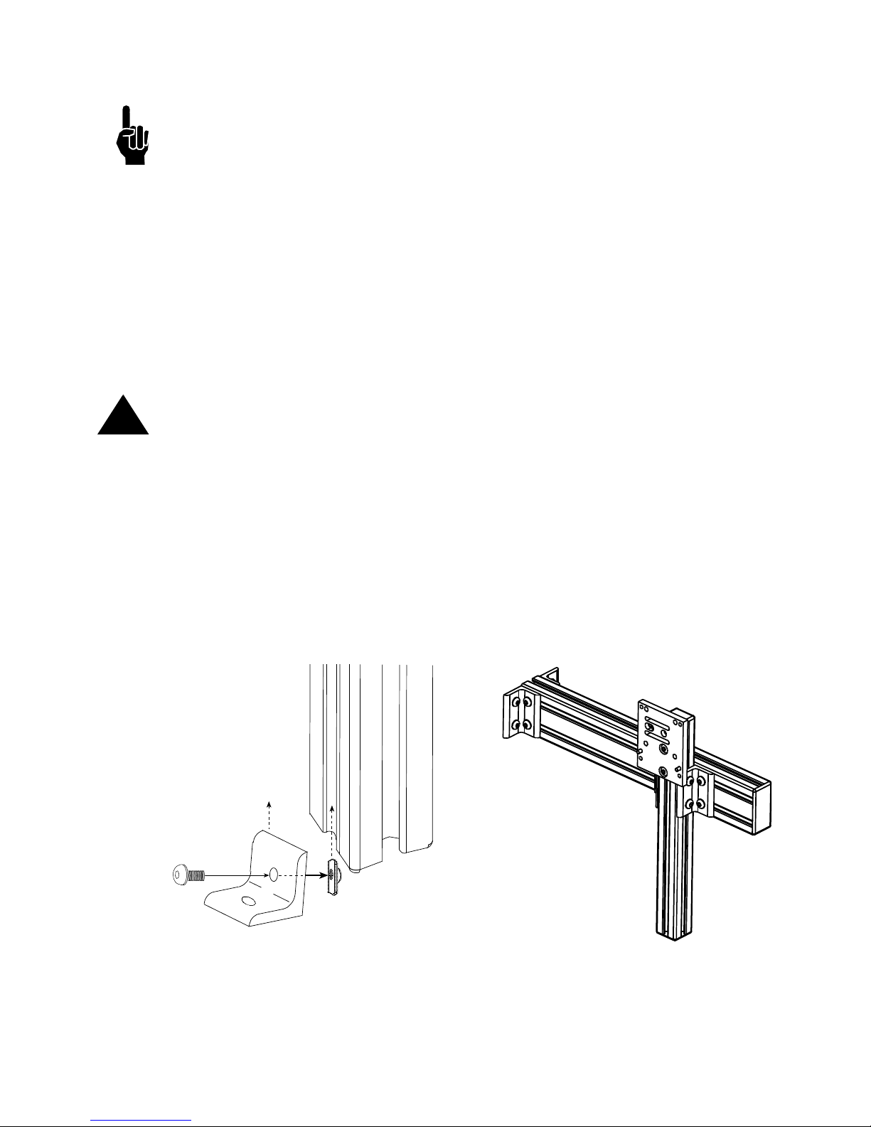
Installing Bracketry
This section shows controller bracketry mounted to a conveyor. This is the most common
mounting method, and the most stable, as all bracketry is bolted directly to the conveyor.
Detailed assembly instructions are included with the parts kit.
Other mounting options, including parts kit numbers, are listed in
ponents.
Corner brackets are attached to aluminum bars as shown.
Section 3, System Com-
2465-623 User Manual Rev E Page 9
Section 4: Installation
Marksman Matrix & Elite
Mounting the Print System
Unpack the print head just before mounting to the bracketry.
Attach the print head to the bracketry with a print head mounting bracket.
The print head must be mounted in close proximity to the product. To maintain consistent
print, the head should be mounted no more than 1/8" from the substrate. An optional
retracting bracket is available to mount the head and control the distance from the head to
the substrate. The retracting bracket allows the head to bump the product and retract as
required to maintain a consistent throw distance. (See
bracketry options.)
NOTE: Install optional retracting bracket kit on the print head prior to mounting the print
head to the conveyor bracket.
It may be necessary to vertically adjust each bracket's horizontal bar later to fine-tune message placement. This is especially true when using multiple print heads, as message lines
will need to be synchronized with each other.
NOTE: When adjusting the horizontal bar or print head mounting bracket, always support
the print head with your hand to keep it from falling forward onto the conveyor.
Section 3, System Components for
NOTE: The ProSeries print heads work on gravity and capillary ink feed, internal in the
print head. The head must be mounted in a level position from front to back to prevent leakage.
2465-623 User Manual Rev E Page 10
Section 4: Installation
Marksman Matrix & Elite
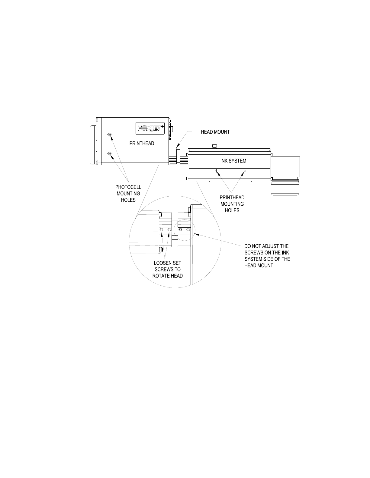
Setting Up the Print Head
The Matrix/Classic Series print heads are mounted using the 10-32 tapped holes on the
right or left side of the Ink System bottom case. The print head angle can be set between 0°
and 90°.
To adjust the head to its correct angle:
1. Loosen the two set screws (1/8" hex head) on the print head side of the head mount.
2. Rotate the head to the desired angle.
3. Secure the set screws.
Mounting the Photosensor
The product detect Photocell can be mounted on either side of the print head, depending
on the direction of print. Remove the plugs or set screws (3/32" hex head) in the photocell
mounting holes, then attach the Photocell Mounting Bracket with the 10-32 x 1/2" screws
provided with the bracket.
2465-623 User Manual Rev E Page 11
Section 4: Installation
Marksman Matrix & Elite
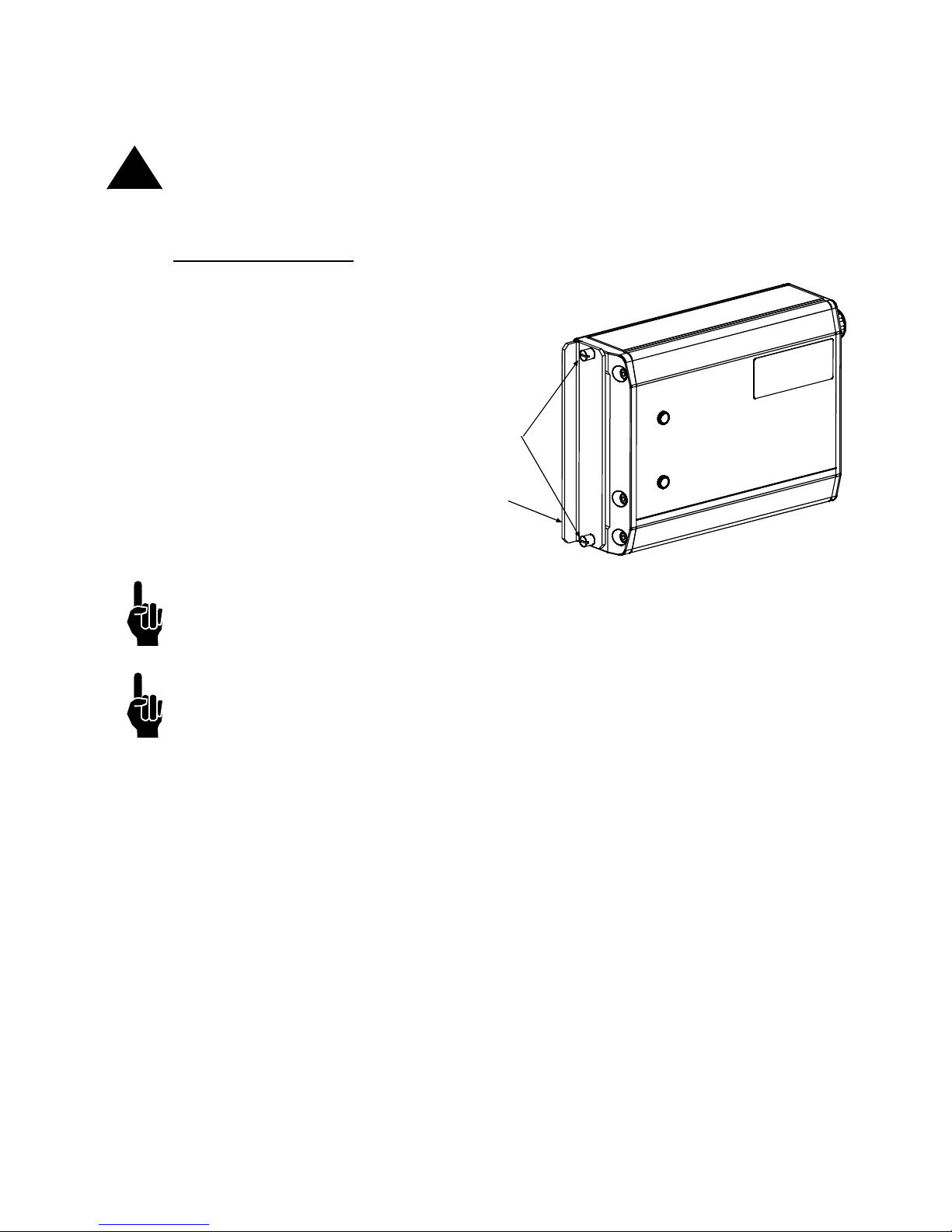
THUMBSCREWS
SHIP CAP
Ship Caps
CAUTION: Do not operate APS Print Heads with the Print Head Ship Cap installed! Oper-
!
ating a closed system can cause a siphoning effect which can drain the ink supply.
384e/768e Print Heads
Loosen the two thumbscrews
and remove the Ship Cap.
(See illustration at right.)
NOTE: If you place the Print Head Ship Cap on a hot print head and do not fasten it
securely, the print head will weep ink until the head has cooled down.
NOTE: Ink may accumulate behind the ship cap during shipping.
2465-623 User Manual Rev E Page 12
Marksman Matrix & Elite
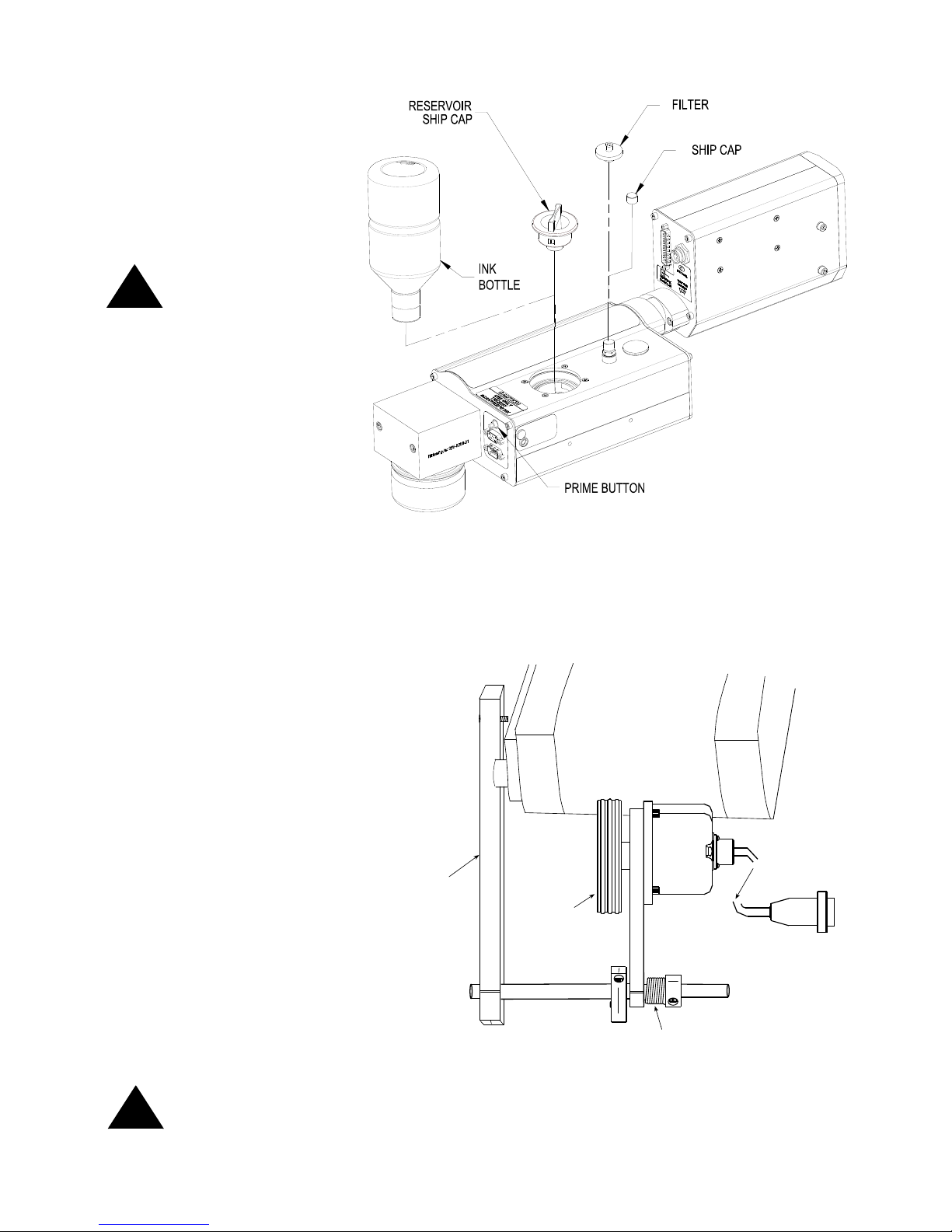
Remove the Ship Cap
Spring
Mounting
Bracket
Encoder
Wheel
Conveyor
Out to Controller
Mounting Bracket
Shaft
Encoder
ENCODER
ASSEMBLY
and Install the Filter.
Remove the Reservoir
Ship Cap and Install
the Ink Bottle. Save
caps in a zip-lock bag
for future use.
CAUTION: Do not
over-tighten the ink
!
bottle when screwing
into the Reservoir.
Over-tightening will
damage the Reservoir.
Section 4: Installation
!
The Encoder
The encoder uses a wheel
that rolls against the conveyor line to track the speed.
It sends a signal to the controller, which makes adjustments for reported changes in
the line speed.
It is not necessary to install
the encoder immediately adjacent to the print heads. It is
more important to place it
where it will accurately measure the speed of the conveyor. Install it in contact with
the conveyor, or with a wheel
or roller moving the same
speed as the conveyor.
The encoder's mounting
bracket is spring-loaded.
Adjust the spring collar to
ensure that the encoder maintains stable contact with the
conveyor.
CAUTION: Do not jam the encoder wheel against the surface of the conveyor. A radial
force of over 40 lbs. will reduce the life of the bearings.
2465-623 User Manual Rev E Page 13
Marksman Matrix & Elite
PRINT
SYSTEM
PRINT HEAD CABLE
PHOTO
SENSOR
ENCODER
SYSTEM
PRINT
ALARM
BEACON
(STROBE)
MARKSMAN MATRIX OR ELITE CONTROLLER
24V
Section 4: Installation
Electrical Cable Connections
2465-623 User Manual Rev E Page 14
Marksman Matrix & Elite
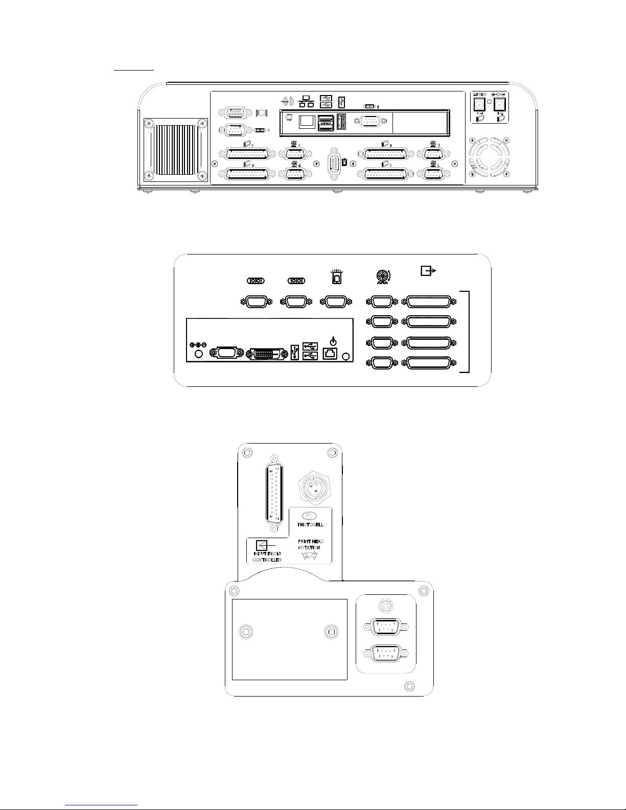
Views
Bottom view of Matrix Controller
(With Optional second PHC Board
ETHERNET
LINE OUT
12 VDC
USB
VGA
DVI-D
COM 1 STROBECOM 2 ENCODER
1
2
OUTPUT TO
PRINTHEAD
4
3
PRINT HEAD CARDS
Bottom view of Elite Controller
Back view of Print System
Section 4: Installation
2465-623 User Manual Rev E Page 15
Section 4: Installation
Marksman Matrix & Elite
Priming the Print Heads
NOTE: The system will not prime either manually or automatically if there is a low ink indi-
cation. Low ink indication is caused by either low ink in the reservoir or full ink in the waste
collection bottle.
Manual Prime
NOTE: Place a wipe in front of the maintenance plate to catch excessive ink.
A manual prime can be accomplished by depressing the push-button switch on the rear of
the ink system housing. Pressing and holding the button for longer than one second will
start the pump for a manual prime. It will continue to run as long as the button is depressed,
or up to five seconds. If additional priming is required, release and press the button again.
Pressing for less than 0.5 seconds will initiate a maintenance cycle. If the system has
started a maintenance cycle and the button is pressed, the manual prime will not operate.
(The Priming Sequence and the Vacuum Cycle are less than 10 seconds long.)
APS Cycle
The APS (Automatic Priming System) cycle is a means for re-priming channels in the head
if some are missing. The APS system does this by using a priming pump to force ink out of
the channels and a vacuum pump and collection bottle to collect the ink waste. The APS
cycle can be manually started by momentarily pressing the prime button.
NOTE: The system may not print during an APS cycle or manual prime.
2465-623 User Manual Rev E Page 16
Section 4: Installation
Marksman Matrix & Elite
0= No APS
UJII Heads Graphics Heads
Switch
Setting
0 1 2 3 4 5 6 7 8 9 A B C D E F
Interval
(Hours)
0 2 4 6 8 10 12 14 16 18 1 2 4 6 8 12
Timing Interval Settings
0
1
2
3
4
5
6
7
8
9
A
B
C
F
E
D
APS View for Printheads
Print Head Control of APS
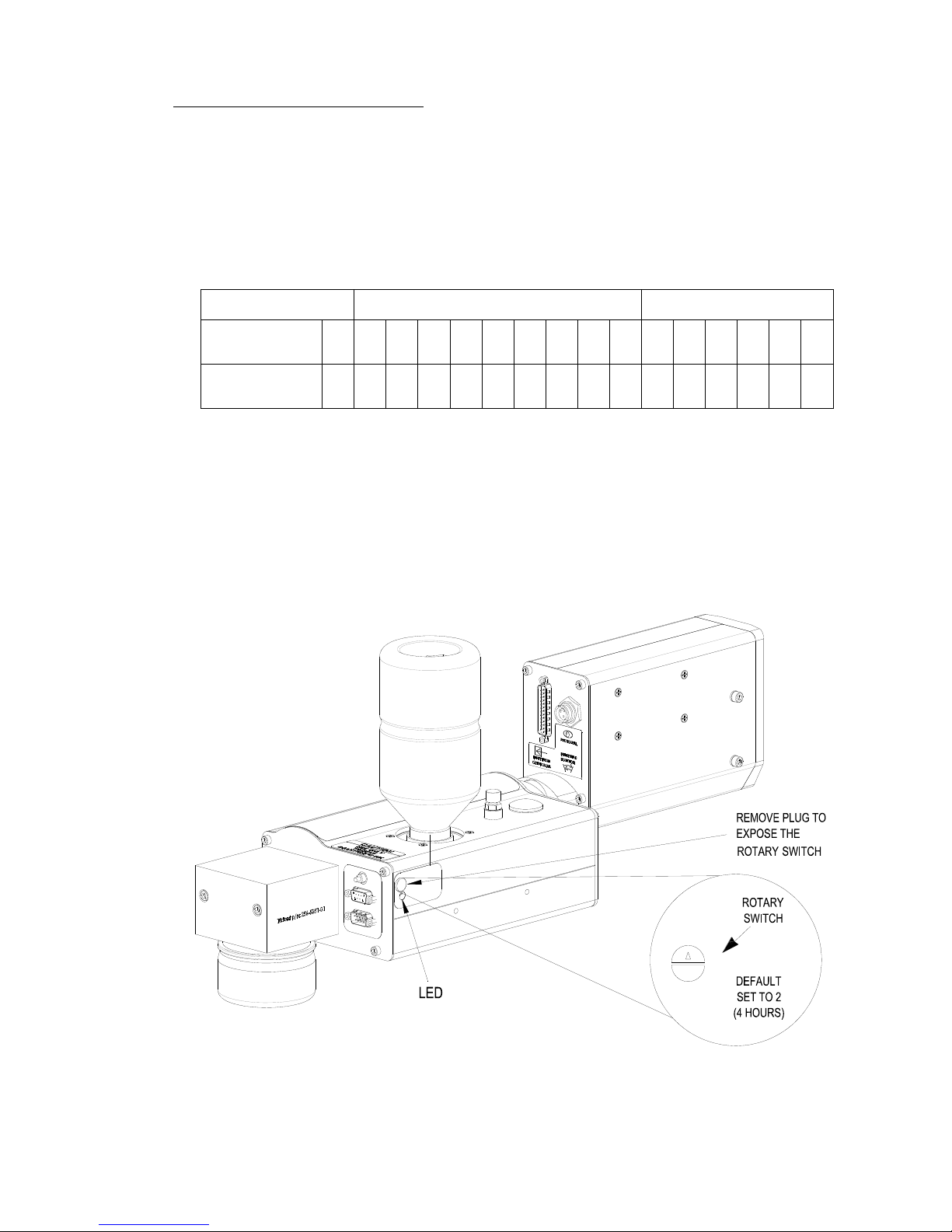
Print Head control of the APS (Automatic Priming System) cycle is accomplished by a programmed timing interval set by the user at the print head (each head, if more then one is
used). It can be set to run as often as necessary, from once every 2 hours to once every 18
hours for the UJII heads; or from once every hour to once every 12 hours for the graphic
heads. The default setting is once every 4 hours (Switch Setting 2 for a UJII head or Switch
Setting C for a graphics head). The interval can be adjusted by means of a rotary switch
(Programmable Timer) mounted on the APS Controller PCB. (See the illustration below.)
See the following Table for the hour interval for each setting of programmable timer.
The priming sequence will perform three separate consecutive primes of approximately
four milliseconds each. The required time for the priming sequence is less than five seconds, with an additional 20 seconds for the vacuum cycle. As with pervious Trident printheads, printing cannot occur during the priming sequence.
2465-623 User Manual Rev E Page 17

Section 4: Installation
Marksman Matrix & Elite
Auxiliary Photocell Input
NOTE: The APS Control Cable and Auxiliary Photocell cannot be used together.
An Auxiliary Photocell input is available to insure a print cycle is not missed during the
automatic priming sequence. Connecting the Auxiliary Photocell will retard a prime
sequence until there is enough time to complete the sequence without missing a print
cycle. The default delay setting is three (3) seconds after the product passes the photocell.
Multiple heads can share the Auxiliary Photocell by using the Photocell "Y" Cable. To
change the default setting, perform the following steps:
1. Insure that the rotary switch is not in the "0" position.
2. Place a box in front of the photocell.
3. While the photocell is on, set the rotary switch to 0.
4. When the LED stays illuminated continuously, set the rotary switch to a new number (1
through F) representing the number of seconds (1 through 15) you want to delay.
"0" is not an available user setting.
5. Press and hold the Prime button until the LED starts flashing.
6. Release the Prime button.
7. Remove the box from in front of the photocell.
8. Set the rotary switch back to the desired hour setting.
Note:
2465-623 User Manual Rev E Page 18
Marksman Matrix & Elite
Section 5: Getting Started
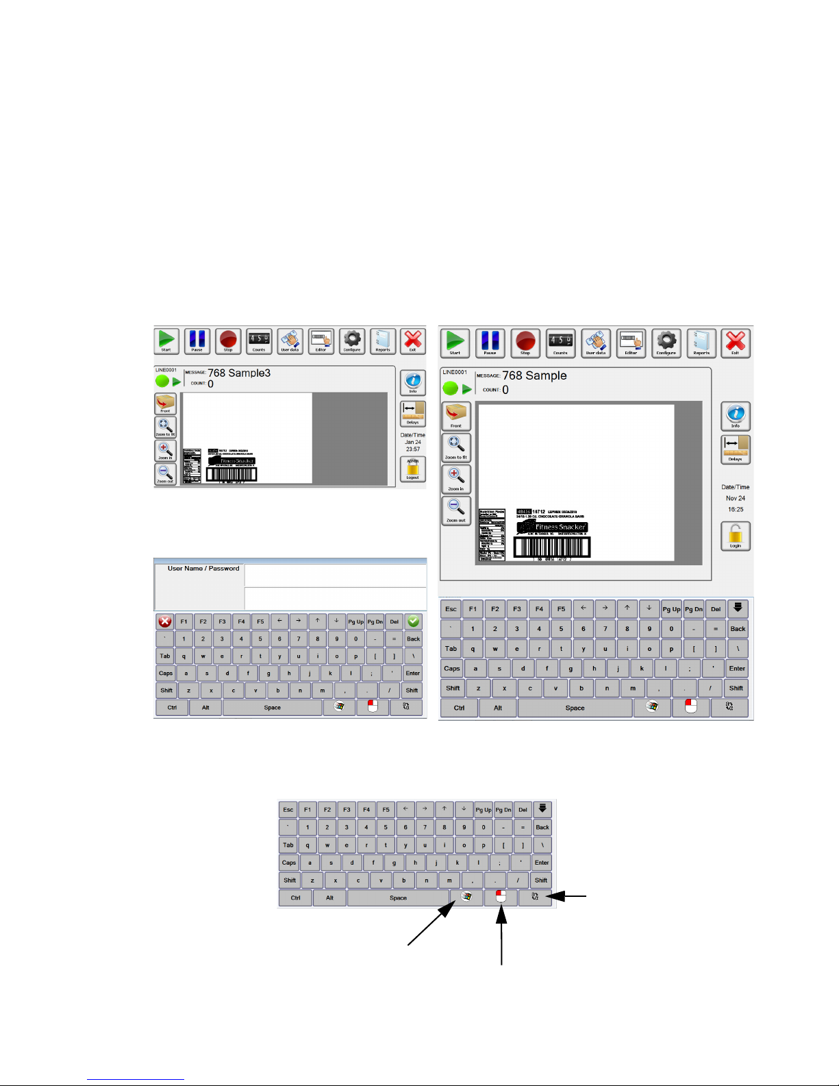
Matrix Version
Elite Version
Matrix keyboard: The keyboard is
called when an input field is selected or
used data is required.
To Windows
Special Function
To change the
key-board language.
Matrix Keyboard
The Marksman Matrix and Elite controllers are standalone units capable of operating one to four printheads, with the addition of an optional controller card. The software has an ICON user interface for is message selection. The main difference
between the two controllers is the size and the resolution of the displays. The resolutions are 1024 x 1280 for the Elite and 1024 x 600 for the Matrix. The extra room
on the Elite display allows for the software keyboard to be accessible at all time.
To get to the keyboard on the Matrix, simply select a field that requires keyboard
input and it will appear. The main dialogs for the print control application (BoxWriter) is shown below:
Section 5: Getting Started
2465-623 User Manual Rev E Page 19
Marksman Matrix & Elite
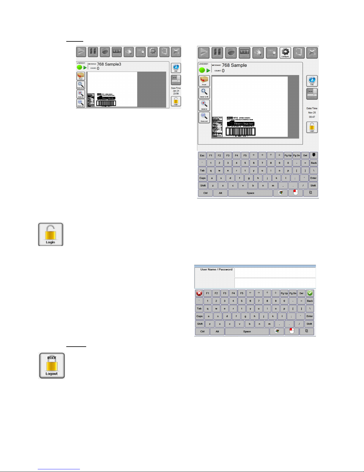
Login
Before Login, Matrix
Before Login, Elite
Default Username and Password:
Username: Admin
Password: FOXJET
(not case sensitive)
Section 5: Getting Started
Select the Login ICON. The following screen will appear for the Matrix. Enter a username
then tab to the next field, enter a password then select the Enter button or the green check
mark. Once logged in the users account will display on the lock.
Note: User names and passwords are not case sensitive.
Logout
Each user should log out of the Marksman© Elite application to enforce the security restrictions. The user may log by selecting the closed padlock icon from the main display. The
system will continue operating in its current state. All menu options are disabled after the
user logs out, with the exception of the Login, Preview options and Info.
2465-623 User Manual Rev E Page 20

Section 5: Getting Started
Marksman Matrix & Elite
Start or Stop Message.
Pause or Resume message being printed.
Change the variable data that is being printed.
Start the Editor that can be used to create or change
messages.
Access to configure the system. See Configure section.
Change the count being printed, if the message contains a count element.
Access to the Printer report and Scan report.
Close BoxWriter to enter Windows desk top.
ICON’s to toggle between info window and Preview
window.
Easy access to the print head’s photocell delay.
Control of preview window and update preview data.
2465-623 User Manual Rev E Page 21
Section 5: Getting Started
Marksman Matrix & Elite
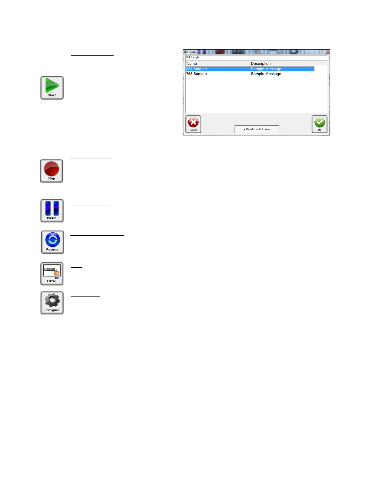
Start Message
The start message is used to ready
the system to print a label or image
that was created with the BoxWriter
Editor.
Select the desired message from the
list, or enter the message name, and
press the OK button.
Reset counts to zero: This allows the
count value to accumulate if needed
or to be reset with the start of the
message.
Stop Message
Stopping a message halts all printing related to the selected production line. The product
count is reset to zero.
The Stop message icon may be selected from the tool bar to stop the task on the
selected production line.
Idle Message
The Idle message option causes the printing to pause on the selected production line.
The product counts are halted until the current message is Resumed
Resume Message
The Resume message option causes the printing to resume on the selected production
line. The product counts are restored from the previously idled message.
Edit
The Edit menu option launches the Marksman BoxWriter Editor application. The user
must have the required rights to use this feature.
Configure
The Configure icon allows access to other options, Print Test Pattern, Database Start,
Print Heads, Production line, System, Security, Help.
See the Configure section in the manual for additional information.
2465-623 User Manual Rev E Page 22
Marksman Matrix & Elite
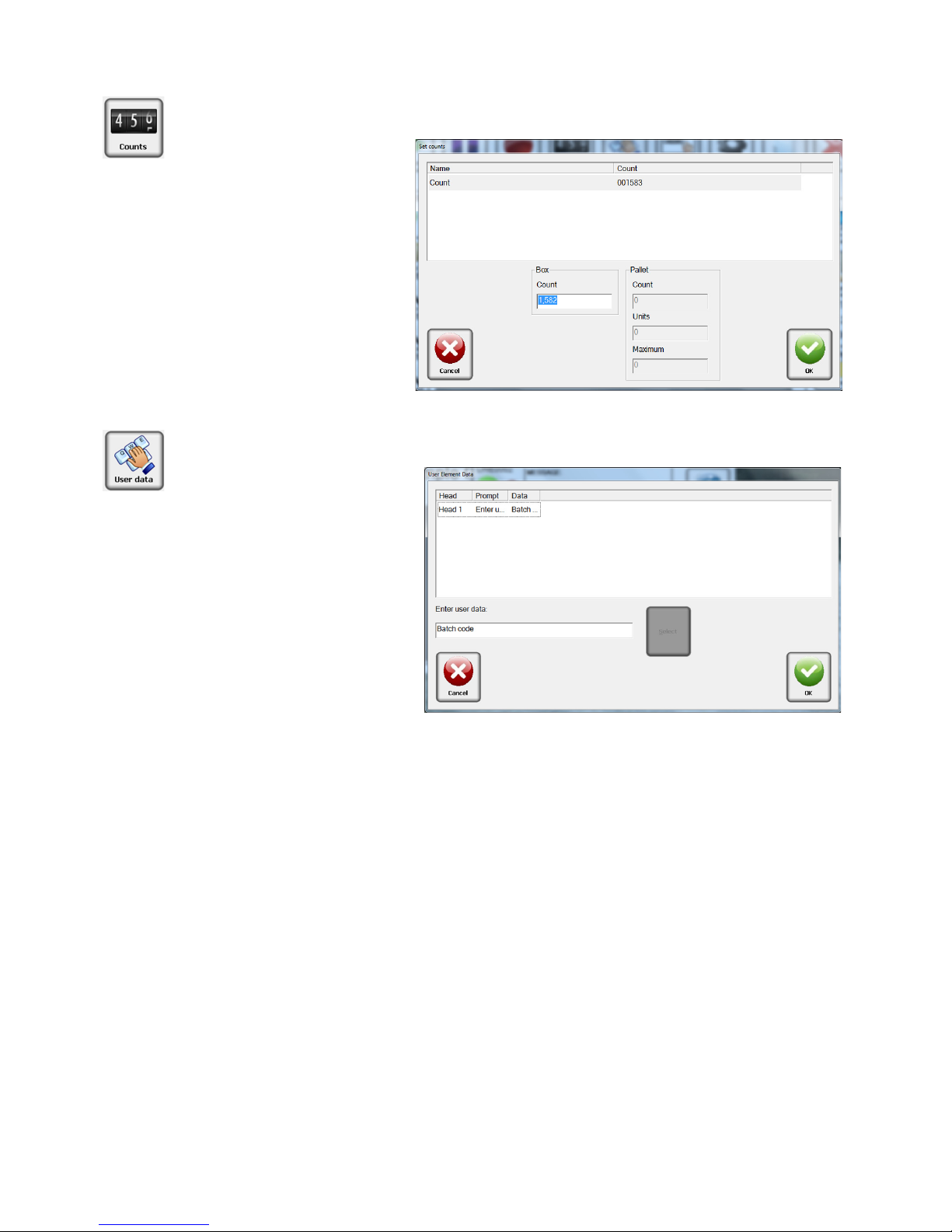
Counts
Count is the current number
of the box in the pallet
series. It is always listed as
the "last printed" box. To
change the Count value,
enter the current box count
value. Enter a
0 to print a
count of 1 on the next box.
User data or User elements
may only be changed if the
message is loaded. The message must contain user elements and be "Running" or
"Idle" in order to modify the
user data.
Select the
User data ICON.
Edit the data in the lower edit
box and press
OK to save
changes. For multiple elements, make all data changes
before pressing
OK to save
changes. Press
Cancel to exit
without saving changes.
User Data
Section 5: Getting Started
2465-623 User Manual Rev E Page 23
Section 5: Getting Started
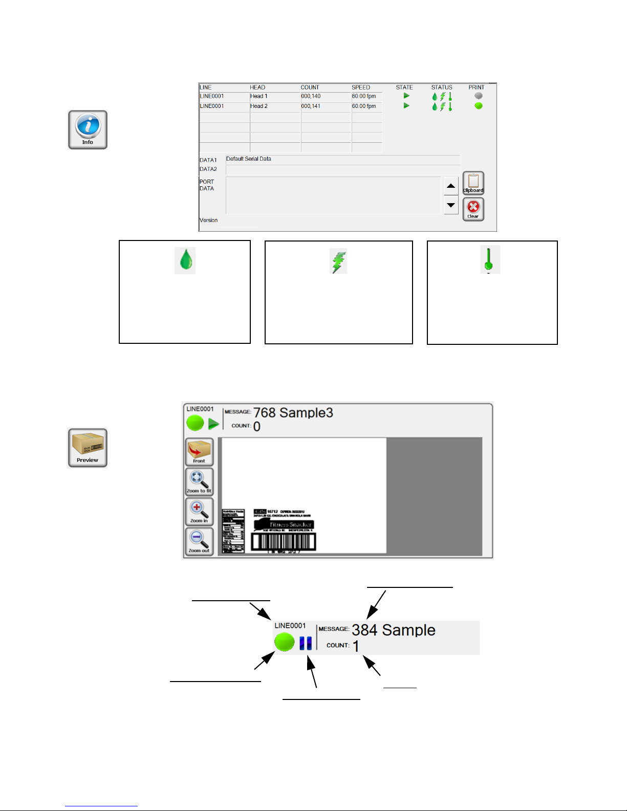
Marksman Matrix & Elite
Print Head Ink level or
Ink Collection bottle
Green = Good
Yellow = Low
Red = Out
Print Head High Voltage
Green = Good
Red = Low
Print Head Temperature
Green = Good
Red = Low
NOTE: The system will not print if the controller is reporting a Low Voltage Error, Out of
Ink condition or Low Temperature condition. If a strobe is connected to the system, this
is represented by a flashing red light.
Current Message
Count:
Next count to be printed
Production Line
Print Head Status:
Green: Ok
Yellow: Low Ink
Red: System Printing Error
Message State:
Printing
Stopped
2465-623 User Manual Rev E Page 24
Marksman Matrix & Elite
Configure, Print Head:
Configure, Print Test Pattern
This function is designed to exercise every channel of the print head to verify all are
printing properly.
When the user clicks the “Test Pattern” button, a test image is generated. Each head on
the currently selected line will print this pattern (along with the print head’s name). In the
example below, the Test Pattern is from Head 1.
Configure, Database Start
Set a message based on data that is located in a database. The database must be setup
before the option is available.
Refer to Appendix F: Database Start
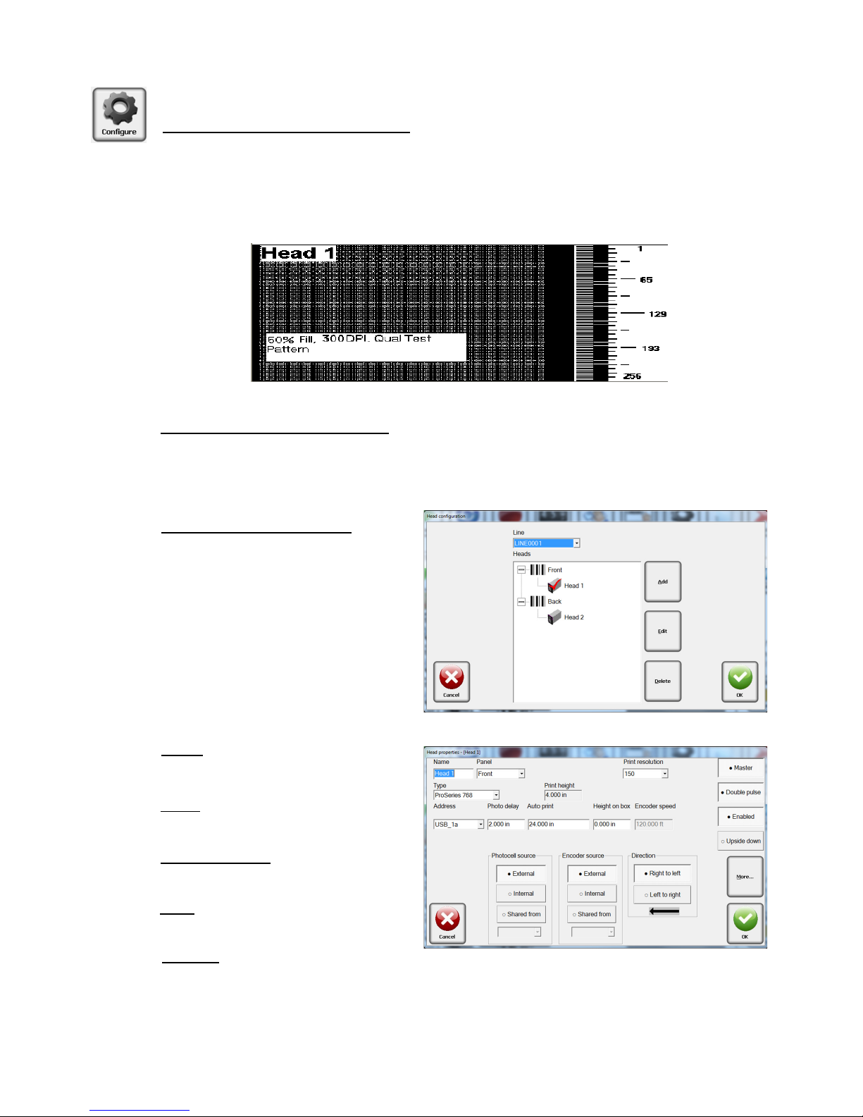
Configure, Print Head
Select Configure, then select Print
Heads from the menu. Select a
panel and click on a head. A head
may be added or removed by
clicking the appropriate Add/
Remove button. To edit a head,
select it and click Edit; or double
click it.
Name: The head’s
user-defined name.
Panel
: The panel which the head
will print on.
Print Resolution
: 150, 200 and 300
dots per inch (dpi).
Type
: Select a head type from the
drop-down menu list.
Address
:
Each card is assigned two heads: 1a and 1b, or 2a and 2b. The cards have jumpers
to determine which card it is. The bottom connector of the card is always the designated as “a”.
Section 5: Getting Started
2465-623 User Manual Rev E Page 25
 Loading...