


User
Manual
Marksman
MATRIX & ELITE
High Resolution Printing
for the Real World
2465-623
Revision E
1 Missouri Research Park Drive • St. Charles, MO 63304
Tel: 800-369-5384 • Fax: 636-300-2188
Illinois Tool Works Inc © 2018

www.foxjet.com
Marksman
MATRIX & ELITE
Ink Jet System
User Manual
2465-623
The information contained in this manual
is correct and accurate at the time of its
publication. ITW reserves the right to
change or alter any information or
technical specifications at any time and
without notice.
©2018 Illinois Tool Works Inc.
All rights reserved

Warranty:
The Marksman© Matrix & Elite Ink Jet system, including all components unless other
wise specified, carries a limited warranty.
The inks and conditioners used with the Marksman© Matrix & Elite Ink Jet system
carry a limited warranty.
For all warranty terms and conditions, contact the Distributor for a complete copy of the
Limited Warranty Statement.

Marksman Matrix & Elite
Section 1: Introduction . . . . . . . . . . . . . . . . . . . . . . . . . . . . . . . . . . . . . . . . . . . . . . . . . . . . . . . . . . . . 1
Section 2: Safety . . . . . . . . . . . . . . . . . . . . . . . . . . . . . . . . . . . . . . . . . . . . . . . . . . . . . . . . . . . . . . . . . . 2
Section 3: System Components . . . . . . . . . . . . . . . . . . . . . . . . . . . . . . . . . . . . . . . . . . . . . . . . . . . . . 3
Integrated Print Head . . . . . . . . . . . . . . . . . . . . . . . . . . . . . . . . . . . . . . . . . . . . . . . . . . . . . . . . . 5
Bracketry . . . . . . . . . . . . . . . . . . . . . . . . . . . . . . . . . . . . . . . . . . . . . . . . . . . . . . . . . . . . . . . . . .6
Photosensor . . . . . . . . . . . . . . . . . . . . . . . . . . . . . . . . . . . . . . . . . . . . . . . . . . . . . . . . . . . . . . . . 7
Encoder . . . . . . . . . . . . . . . . . . . . . . . . . . . . . . . . . . . . . . . . . . . . . . . . . . . . . . . . . . . . . . . . . . . 7
Inks . . . . . . . . . . . . . . . . . . . . . . . . . . . . . . . . . . . . . . . . . . . . . . . . . . . . . . . . . . . . . . . . . . . . . . 7
Waste Bottle . . . . . . . . . . . . . . . . . . . . . . . . . . . . . . . . . . . . . . . . . . . . . . . . . . . . . . . . . . . . . . . 7
Section 4: Installation . . . . . . . . . . . . . . . . . . . . . . . . . . . . . . . . . . . . . . . . . . . . . . . . . . . . . . . . . . . . . 8
Materials Required for Installation . . . . . . . . . . . . . . . . . . . . . . . . . . . . . . . . . . . . . . . . . . . . . . 8
System Installation Overview . . . . . . . . . . . . . . . . . . . . . . . . . . . . . . . . . . . . . . . . . . . . . . . . . . 9
Installing Bracketry . . . . . . . . . . . . . . . . . . . . . . . . . . . . . . . . . . . . . . . . . . . . . . . . . . . . . . . . . . 9
Mounting the Print System . . . . . . . . . . . . . . . . . . . . . . . . . . . . . . . . . . . . . . . . . . . . . . . . . . . 10
Setting Up the Print Head . . . . . . . . . . . . . . . . . . . . . . . . . . . . . . . . . . . . . . . . . . . . . . . . . . . . 11
Mounting the Photosensor . . . . . . . . . . . . . . . . . . . . . . . . . . . . . . . . . . . . . . . . . . . . . . . . . . . . 11
Ship Caps . . . . . . . . . . . . . . . . . . . . . . . . . . . . . . . . . . . . . . . . . . . . . . . . . . . . . . . . . . . . . . . . . 12
The Encoder . . . . . . . . . . . . . . . . . . . . . . . . . . . . . . . . . . . . . . . . . . . . . . . . . . . . . . . . . . . . . . . 13
Electrical Cable Connections . . . . . . . . . . . . . . . . . . . . . . . . . . . . . . . . . . . . . . . . . . . . . . . . .14
Priming the Print Heads . . . . . . . . . . . . . . . . . . . . . . . . . . . . . . . . . . . . . . . . . . . . . . . . . . . . . . 16
Section 5: Getting Started . . . . . . . . . . . . . . . . . . . . . . . . . . . . . . . . . . . . . . . . . . . . . . . . . . . . . . . . . 19
Counts . . . . . . . . . . . . . . . . . . . . . . . . . . . . . . . . . . . . . . . . . . . . . . . . . . . . . . . . . . . . . . . . . . . 23
User Data . . . . . . . . . . . . . . . . . . . . . . . . . . . . . . . . . . . . . . . . . . . . . . . . . . . . . . . . . . . . . . . . . 23
Configure, Print Head: . . . . . . . . . . . . . . . . . . . . . . . . . . . . . . . . . . . . . . . . . . . . . . . . . . . . . . . 25
Configure, System . . . . . . . . . . . . . . . . . . . . . . . . . . . . . . . . . . . . . . . . . . . . . . . . . . . . . . . . . . 28
Reports . . . . . . . . . . . . . . . . . . . . . . . . . . . . . . . . . . . . . . . . . . . . . . . . . . . . . . . . . . . . . . . . . . . 32
Delays . . . . . . . . . . . . . . . . . . . . . . . . . . . . . . . . . . . . . . . . . . . . . . . . . . . . . . . . . . . . . . . . . . . 33
Section 6: BoxWriter© Matrix & Elite Editor . . . . . . . . . . . . . . . . . . . . . . . . . . . . . . . . . . . . . . . . 34
Define . . . . . . . . . . . . . . . . . . . . . . . . . . . . . . . . . . . . . . . . . . . . . . . . . . . . . . . . . . . . . . . . . . . 34
Tools . . . . . . . . . . . . . . . . . . . . . . . . . . . . . . . . . . . . . . . . . . . . . . . . . . . . . . . . . . . . . . . . . . . . 47
Files . . . . . . . . . . . . . . . . . . . . . . . . . . . . . . . . . . . . . . . . . . . . . . . . . . . . . . . . . . . . . . . . . . . . .47
Elements . . . . . . . . . . . . . . . . . . . . . . . . . . . . . . . . . . . . . . . . . . . . . . . . . . . . . . . . . . . . . . . . . 56
ToolBar . . . . . . . . . . . . . . . . . . . . . . . . . . . . . . . . . . . . . . . . . . . . . . . . . . . . . . . . . . . . . . . . . . 69
Perspective . . . . . . . . . . . . . . . . . . . . . . . . . . . . . . . . . . . . . . . . . . . . . . . . . . . . . . . . . . . . . . . . 79
Section 7: Maintenance . . . . . . . . . . . . . . . . . . . . . . . . . . . . . . . . . . . . . . . . . . . . . . . . . . . . . . . . . . . 81
APS - Automatic Priming System . . . . . . . . . . . . . . . . . . . . . . . . . . . . . . . . . . . . . . . . . . . . . . 81
Shutdown Procedures . . . . . . . . . . . . . . . . . . . . . . . . . . . . . . . . . . . . . . . . . . . . . . . . . . . . . . . 82
Ink Storage . . . . . . . . . . . . . . . . . . . . . . . . . . . . . . . . . . . . . . . . . . . . . . . . . . . . . . . . . . . . . . . . 84
Section 8: Troubleshooting . . . . . . . . . . . . . . . . . . . . . . . . . . . . . . . . . . . . . . . . . . . . . . . . . . . . . . . . 85
Troubleshooting Notes . . . . . . . . . . . . . . . . . . . . . . . . . . . . . . . . . . . . . . . . . . . . . . . . . . . . . .85
Troubleshooting Tests . . . . . . . . . . . . . . . . . . . . . . . . . . . . . . . . . . . . . . . . . . . . . . . . . . . . . . . 86
Print Quality Troubleshooting . . . . . . . . . . . . . . . . . . . . . . . . . . . . . . . . . . . . . . . . . . . . . . . . .87
2465-623 User Manual Rev E

Marksman Matrix & Elite
Appendix A: Specifications . . . . . . . . . . . . . . . . . . . . . . . . . . . . . . . . . . . . . . . . . . . . . . . . . . . . . . . . 90
Matrix Controller Specifications . . . . . . . . . . . . . . . . . . . . . . . . . . . . . . . . . . . . . . . . . . . . . . 90
Elite Controller Specifications . . . . . . . . . . . . . . . . . . . . . . . . . . . . . . . . . . . . . . . . . . . . . . . . 91
Print Head Specifications . . . . . . . . . . . . . . . . . . . . . . . . . . . . . . . . . . . . . . . . . . . . . . . . . . . . 92
Appendix B: Theory of Operation . . . . . . . . . . . . . . . . . . . . . . . . . . . . . . . . . . . . . . . . . . . . . . . . . . 94
The Marksman© Matrix & Elite . . . . . . . . . . . . . . . . . . . . . . . . . . . . . . . . . . . . . . . . . . . . . . . 94
Print Heads . . . . . . . . . . . . . . . . . . . . . . . . . . . . . . . . . . . . . . . . . . . . . . . . . . . . . . . . . . . . . . .94
Photosensor . . . . . . . . . . . . . . . . . . . . . . . . . . . . . . . . . . . . . . . . . . . . . . . . . . . . . . . . . . . . . . . 94
Encoder . . . . . . . . . . . . . . . . . . . . . . . . . . . . . . . . . . . . . . . . . . . . . . . . . . . . . . . . . . . . . . . . . . 94
Matrix Wiring Diagram . . . . . . . . . . . . . . . . . . . . . . . . . . . . . . . . . . . . . . . . . . . . . . . . . . . . . . 95
Elite Wiring Diagram . . . . . . . . . . . . . . . . . . . . . . . . . . . . . . . . . . . . . . . . . . . . . . . . . . . . . . . 96
Appendix C: Parts and Supplies . . . . . . . . . . . . . . . . . . . . . . . . . . . . . . . . . . . . . . . . . . . . . . . . . . . 97
Consumables . . . . . . . . . . . . . . . . . . . . . . . . . . . . . . . . . . . . . . . . . . . . . . . . . . . . . . . . . . . . . . 97
Matrix Spare Parts Kits . . . . . . . . . . . . . . . . . . . . . . . . . . . . . . . . . . . . . . . . . . . . . . . . . . . . . . 97
Elite Spare Parts Kits . . . . . . . . . . . . . . . . . . . . . . . . . . . . . . . . . . . . . . . . . . . . . . . . . . . . . . . . 97
Accessories . . . . . . . . . . . . . . . . . . . . . . . . . . . . . . . . . . . . . . . . . . . . . . . . . . . . . . . . . . . . . . . 97
384e and 768e Print System Service Kit . . . . . . . . . . . . . . . . . . . . . . . . . . . . . . . . . . . . . . . . . 98
Appendix D: Testing the Electrical Outlet . . . . . . . . . . . . . . . . . . . . . . . . . . . . . . . . . . . . . . . . . . . 99
Electrical Line Transients . . . . . . . . . . . . . . . . . . . . . . . . . . . . . . . . . . . . . . . . . . . . . . . . . . . . 99
Appendix E: Database Start . . . . . . . . . . . . . . . . . . . . . . . . . . . . . . . . . . . . . . . . . . . . . . . . . . . . . . 100
Description . . . . . . . . . . . . . . . . . . . . . . . . . . . . . . . . . . . . . . . . . . . . . . . . . . . . . . . . . . . . . . 100
Database Start Task Routine Flowchart . . . . . . . . . . . . . . . . . . . . . . . . . . . . . . . . . . . . . . . . 100
Database Lookup Definition - Global Setting . . . . . . . . . . . . . . . . . . . . . . . . . . . . . . . . . . . . 101
Database Start Task . . . . . . . . . . . . . . . . . . . . . . . . . . . . . . . . . . . . . . . . . . . . . . . . . . . . . . . . 102
Serial Port Modification . . . . . . . . . . . . . . . . . . . . . . . . . . . . . . . . . . . . . . . . . . . . . . . . . . . . 102
Printer Report Modification . . . . . . . . . . . . . . . . . . . . . . . . . . . . . . . . . . . . . . . . . . . . . . . . . 103
Appendix F: Hand Scanner . . . . . . . . . . . . . . . . . . . . . . . . . . . . . . . . . . . . . . . . . . . . . . . . . . . . . . 104
Scan and Shoot Setup . . . . . . . . . . . . . . . . . . . . . . . . . . . . . . . . . . . . . . . . . . . . . . . . . . . . . . 104
Scanner . . . . . . . . . . . . . . . . . . . . . . . . . . . . . . . . . . . . . . . . . . . . . . . . . . . . . . . . . . . . . . . . . 105
Appendix G: Fonts . . . . . . . . . . . . . . . . . . . . . . . . . . . . . . . . . . . . . . . . . . . . . . . . . . . . . . . . . . . . . 107
Font List . . . . . . . . . . . . . . . . . . . . . . . . . . . . . . . . . . . . . . . . . . . . . . . . . . . . . . . . . . . . . . . . . 107
Font Samples . . . . . . . . . . . . . . . . . . . . . . . . . . . . . . . . . . . . . . . . . . . . . . . . . . . . . . . . . . . . . 108
Appendix H: Standard Operating Procedures . . . . . . . . . . . . . . . . . . . . . . . . . . . . . . . . . . . . . . . 113
FJSOP1 - Removal of FoxJet High Resolution Printheads . . . . . . . . . . . . . . . . . . . . . . . . . . 113
FJSOP2 - Daily Maintenance for AMS/APS Printheads . . . . . . . . . . . . . . . . . . . . . . . . . . . 115
FJSOP4 - Installation of FoxJet High Resolution AMS/APS Printheads . . . . . . . . . . . . . . .117
2465-623 User Manual Rev E

Marksman Matrix & Elite
Section 1: Introduction
The Marksman© Matrix & Elite are advanced high-resolution ink jet controllers that runs on
a Microsoft Windows 7® platform. It includes a built-in keypad with a TFT display with
touch-screen control. The Marksman© Matrix & Elite can control up to 4 Pro Series highresolution print heads for printing industry compliant barcodes, graphics or alphanumeric
text on porous materials and cases.
This manual covers the operation of the Marksman© Matrix & Elite Ink Jet Printing System,
Marksman© Matrix & Elite Controller and Print Heads.
Section 1: Introduction
2465-623 User Manual Rev E Page 1
Marksman Matrix & Elite
Section 2: Safety
Following is a list of safety symbols and their meanings, which will be found throughout this
manual. Pay attention to these symbols where they appear in the manual.
Wear safety goggles when performing the procedure described!
Caution or Warning! Denotes possible personal injury and/or damage to the equip-
!
ment.
Caution or Warning! Denotes possible personal injury and/or equipment damage
due to electrical hazard.
NOTE: (Will be followed by a brief comment or explanation.)
Section 2: Safety
Only trained personnel should operate and service the equipment.
NOTE: It is extremely important to:
• Clean up all ink spills with the appropriate conditioners immediately and dispose of all
waste according to local and state regulations.
• Wear safety glasses and protective clothing, including gloves, when handling all inks
and conditioners.
• Store inks and conditioners under the recommended conditions found on the MSDS
(Material Safety Data Sheet).
PRODUCT COMPLIANCE DISCLAIMER NOTE:
This product meets the requirements of CAN/CSA-22.2 NO.60950-00 * UL 60950 using
FoxJet an ITW Company approved items. Units are only tested and qualified with FoxJet
an ITW Company approved inks, parts and accessories. Use of other inks, parts or accessories may introduce potential risks that FoxJet an ITW Company can assume no liability
for.
2465-623 User Manual Rev E Page 2
Marksman Matrix & Elite
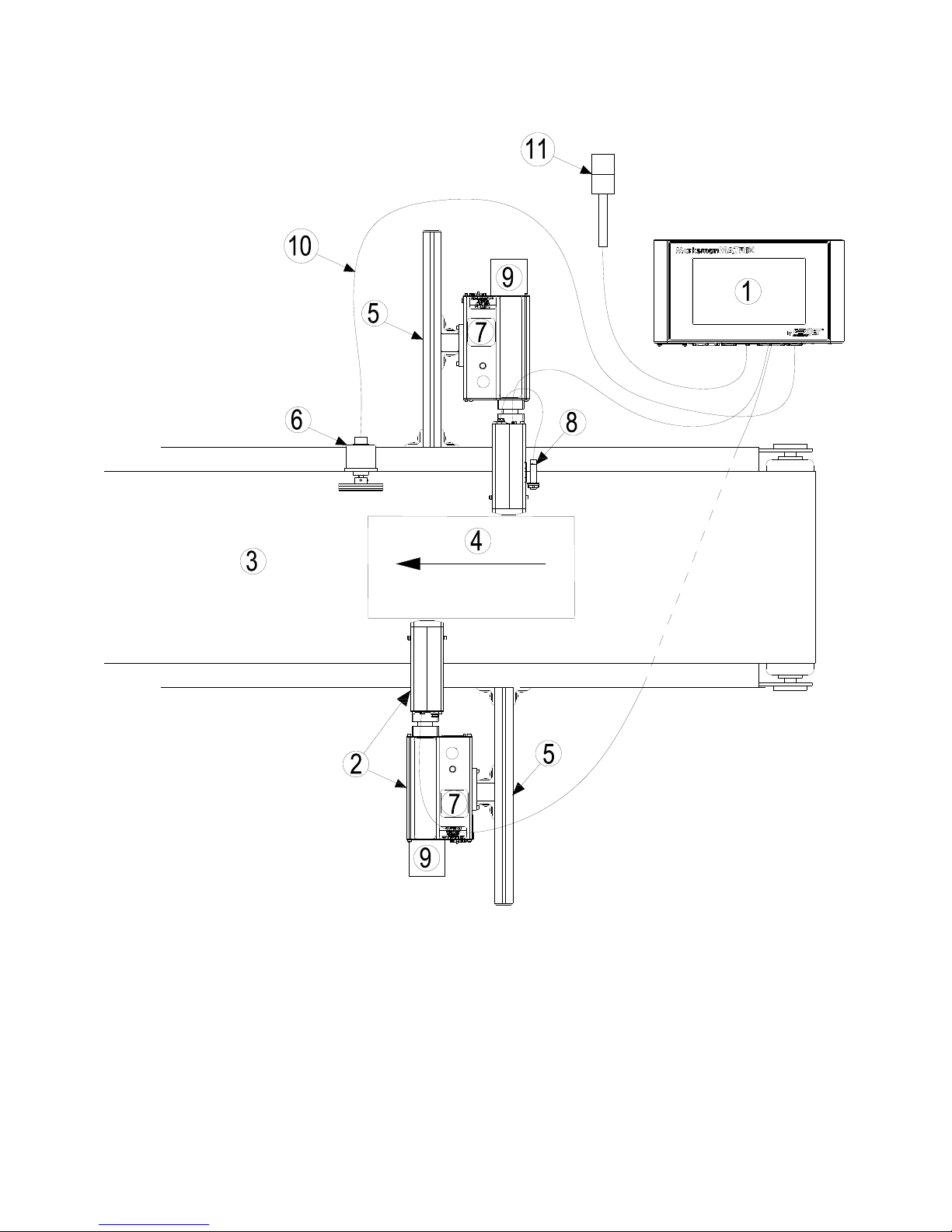
Section 3: System Components
1 Controller, Matrix or Elite
2 Proseries Print Head
3 Conveyor
4 Product
5 Print System Bracketry
6 Encoder
7 Ink Supply
8 Photo Sensor
9 Vacuum Waste Collector Bottle
10 Encoder Cable
11 Alarm Beacon (Strobe)
Section 3: System Components
2465-623 User Manual Rev E Page 3

Section 3: System Components
Marksman Matrix & Elite
The Marksman© Ink Jet System is available with the following components, options and
service kits:
Part Number
2464076 ProSeries 384e
2464076F ProSeries 384e, Flushed
2464078 ProSeries 384e, 90°
2464078F ProSeries 384e, 90°, Flushed
2464079 ProSeries 384e, Modular
2464079F ProSeries 384e, Modular, Flushed
2464082 ProSeries 768e
2464082F ProSeries 768e, Flushed
2464083 ProSeries 768e, Modular
2464083F ProSeries 768e, Modular, Flushed
2464084 ProSeries 768e, 90 Degree
2464084F ProSeries 768e, 90 Degree, Flushed
2465006D2 Controller Assembly, Marksman© Matrix, 2 Head, Domestic
2465006E2 Controller Assembly, Marksman© Matrix, 2 Head, European
2465006D4 Controller Assembly, Marksman© Matrix, 4 Head, Domestic
2465006E4 Controller Assembly, Marksman© Matrix, 4 Head, European
2465004D2 Controller Assembly, Marksman© Elite, 2 Head, Domestic
2465004E2 Controller Assembly, Marksman© Elite, 2 Head, European
Description
Print Head
Matrix Controller Assembly
Elite Controller Assembly
Remote PHC Board & Elite board kit
2465321 Assembly, Marksman remote PHC Board
2465246 Elite PHC Board Kit
Print Head/Controller Bracketry
2464550 Print Head Conveyor Mount Bracket
2464553 Print Head Pivot Bracket
2464561 X-Y Axis Linear Adjustment, Tool-Less Bracket
2464562 Conveyor Mount/Roller Bracket for 768 Print Head
2464563 Print Head Floor Mount Bracket Kit
2464564 Conveyor Mount/Roller Bracket for 384/352 Print Head
2464565 Conveyor Mounting Bracket with Integrated Guide Rails for 384/768 Print Head
2465243 Kit, T-Stand, Matrix & Elite
2465244 Kit, Conveyor Mounting, Matrix & Elite
2465254 Kit, Pivot Bracket, Matrix & Elite
Encoder, Photosensor, Alarm Beacon
2465224 Photosensor, ProSeries
2465253 Alarm Beacon (Strobe), 3-Color
2465525 Photosensor, Auxiliary, APS Controller
2465-623 User Manual Rev E Page 4

Section 3: System Components
Marksman Matrix & Elite
INK SYSTEM
WASTE BOTTLE
PRINT HEAD
INK BOTTLE
Cabling
2464182-010 Cable, Straight Thru, DB9, 10 Ft.
2464182-025 Cable, Straight Thru, DB9, 25Ft.
2464182-050 Cable, Straight Thru, DB9, 50 Ft.
2465155-002 Cable Kit, Print Head, DB25, 2 Ft.
2465155-010 Cable Kit, Print Head, DB25, 10 Ft.
2465155-025 Cable Kit, Print Head, DB25, 25 Ft.
2464312 Cable, APS Photocell Network ("Y" Cable for sharing Auxiliary Photocell)
Integrated Print Head
2465-623 User Manual Rev E Page 5
Section 3: System Components
Marksman Matrix & Elite
Retracting Bracket
Floor Mount
Conveyor Mount
Bracketry
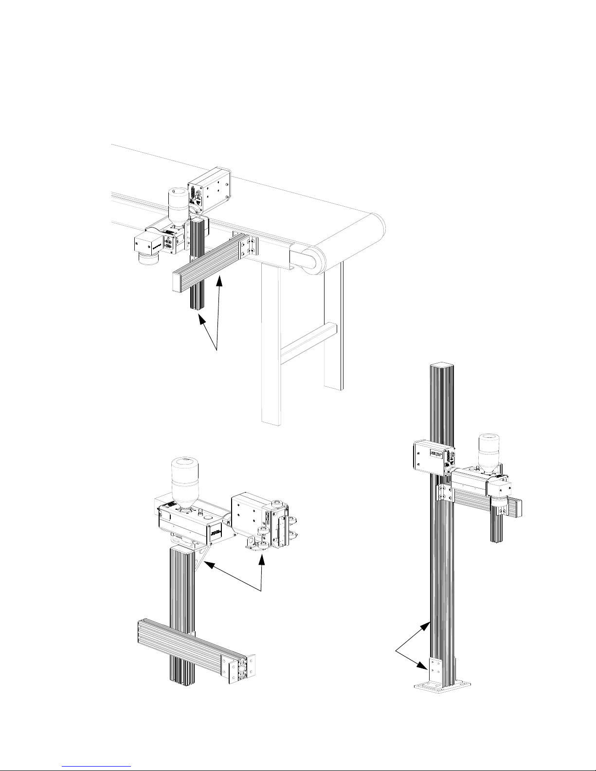
Bracketry is the structure that supports the controller, print system and other accessories.
This manual details instructions for mounting all system components to a conveyor. Other
mounting options for the controller and print system include the floor mount and the retracting bracket. Assembly instructions are included with parts kits.
2465-623 User Manual Rev E Page 6
Section 3: System Components
Marksman Matrix & Elite
ENCODER ASSEMBLY
Photosensor
The photosensor is both a light source and a sensor. It emits light and detects the arrival of
a product when the product reflects the light source back to the sensor. The sensor then
sends a signal to the controller to start the printing cycle.
Encoder
The encoder assembly provides conveyor line
speed information to the controller. It also allows
automatic disabling of printing when the line
stops.
The Marksman© Matrix & Elite System uses a
5000 ppr open collector output encoder. The
wheel is sized to provide the correct timing
inputs to allow the print heads to print from 150
to 300 dpi.
Inks
Ink is supplied via 500 mL plastic containers. ScanTrue® II PLUS is a pigmented ink formulated for use on porous substrates.
NOTE: Check the label on the Print Head for correct ink type.
NOTE: Inks are not miscible. Do NOT
mix the inks.
Waste Bottle
The APS includes a Waste Collection Bottle mounted on the rear of the Print Head assembly. This bottle must be changed when full to prevent improper operation of the system.
Instructions for waste disposal are on the collection bottle.
2465-623 User Manual Rev E Page 7
Marksman Matrix & Elite
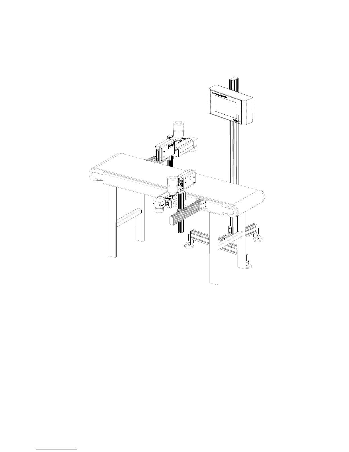
Section 4: Installation
The figure below illustrates a typical conveyor-mounted installation. (Cables are not
shown.)
Section 4: Installation
Materials Required for Installation
You will need the following items:
• Lint-free wipes
• Safety goggles
•Level
• Tape measure
Use appropriate safety equipment and procedures. Leave print heads in their shipping cartons until all bracketry is in place and tightened down.
2465-623 User Manual Rev E Page 8
Section 4: Installation
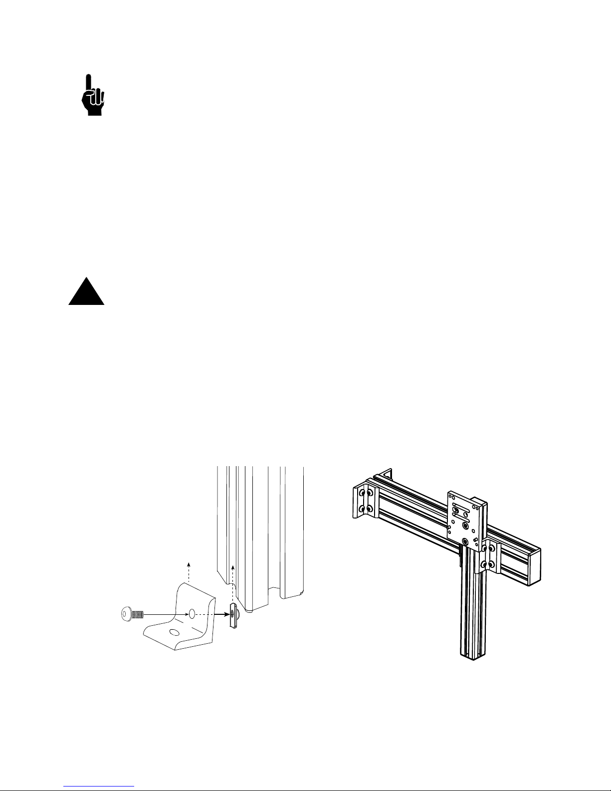
Marksman Matrix & Elite
ATTACH ING
CORNER
BRACKET
Single T-nut
Corner Bracket
System Installation Overview
NOTE: The following steps give an overview of the procedure to properly install the Marks-
man© Matrix or Elite print system. Refer to the appropriate section for details.
1. Carefully plan the mounting location of the equipment. Keep in mind bracketry hardware location and printer equipment size.
2. Remove equipment from packaging.
3. Assemble all bracketry to the floor, conveyor, or other bracketry per bracketry installation section.
4. Mount the print system to its appropriate bracketry. Do not connect to power outlet.
5. Assemble the optional retracting bracket to each print head, if applicable.
6. Mount the print head(s) to their appropriate bracketry and in the approximate location
relative to the carton.
7. Mount the photosensor, optional bracketry, and optional encoder per procedure.
CAUTION: Remove the print head Ship Cap prior to operating the Print Heads.
!
Installing Bracketry
This section shows controller bracketry mounted to a conveyor. This is the most common
mounting method, and the most stable, as all bracketry is bolted directly to the conveyor.
Detailed assembly instructions are included with the parts kit.
Other mounting options, including parts kit numbers, are listed in
ponents.
Corner brackets are attached to aluminum bars as shown.
Section 3, System Com-
2465-623 User Manual Rev E Page 9
Section 4: Installation
Marksman Matrix & Elite
Mounting the Print System
Unpack the print head just before mounting to the bracketry.
Attach the print head to the bracketry with a print head mounting bracket.
The print head must be mounted in close proximity to the product. To maintain consistent
print, the head should be mounted no more than 1/8" from the substrate. An optional
retracting bracket is available to mount the head and control the distance from the head to
the substrate. The retracting bracket allows the head to bump the product and retract as
required to maintain a consistent throw distance. (See
bracketry options.)
NOTE: Install optional retracting bracket kit on the print head prior to mounting the print
head to the conveyor bracket.
It may be necessary to vertically adjust each bracket's horizontal bar later to fine-tune message placement. This is especially true when using multiple print heads, as message lines
will need to be synchronized with each other.
NOTE: When adjusting the horizontal bar or print head mounting bracket, always support
the print head with your hand to keep it from falling forward onto the conveyor.
Section 3, System Components for
NOTE: The ProSeries print heads work on gravity and capillary ink feed, internal in the
print head. The head must be mounted in a level position from front to back to prevent leakage.
2465-623 User Manual Rev E Page 10
Section 4: Installation
Marksman Matrix & Elite
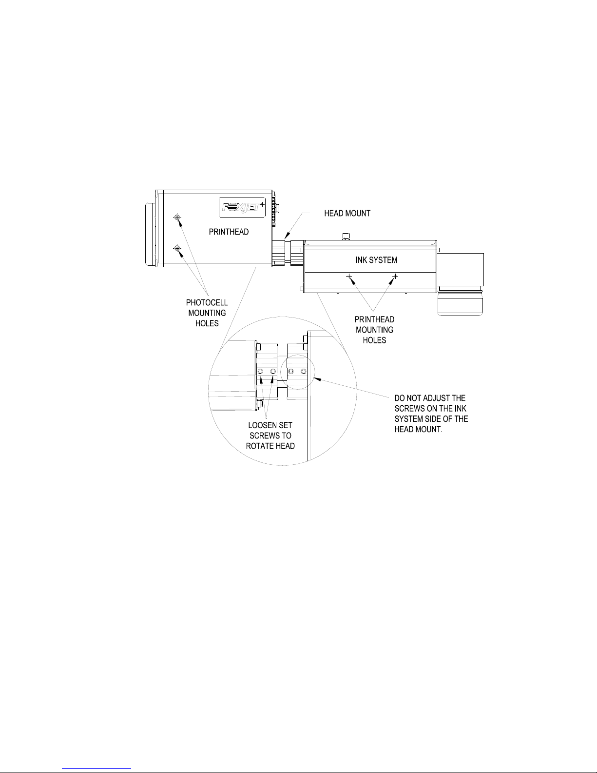
Setting Up the Print Head
The Matrix/Classic Series print heads are mounted using the 10-32 tapped holes on the
right or left side of the Ink System bottom case. The print head angle can be set between 0°
and 90°.
To adjust the head to its correct angle:
1. Loosen the two set screws (1/8" hex head) on the print head side of the head mount.
2. Rotate the head to the desired angle.
3. Secure the set screws.
Mounting the Photosensor
The product detect Photocell can be mounted on either side of the print head, depending
on the direction of print. Remove the plugs or set screws (3/32" hex head) in the photocell
mounting holes, then attach the Photocell Mounting Bracket with the 10-32 x 1/2" screws
provided with the bracket.
2465-623 User Manual Rev E Page 11
Section 4: Installation
Marksman Matrix & Elite
THUMBSCREWS
SHIP CAP
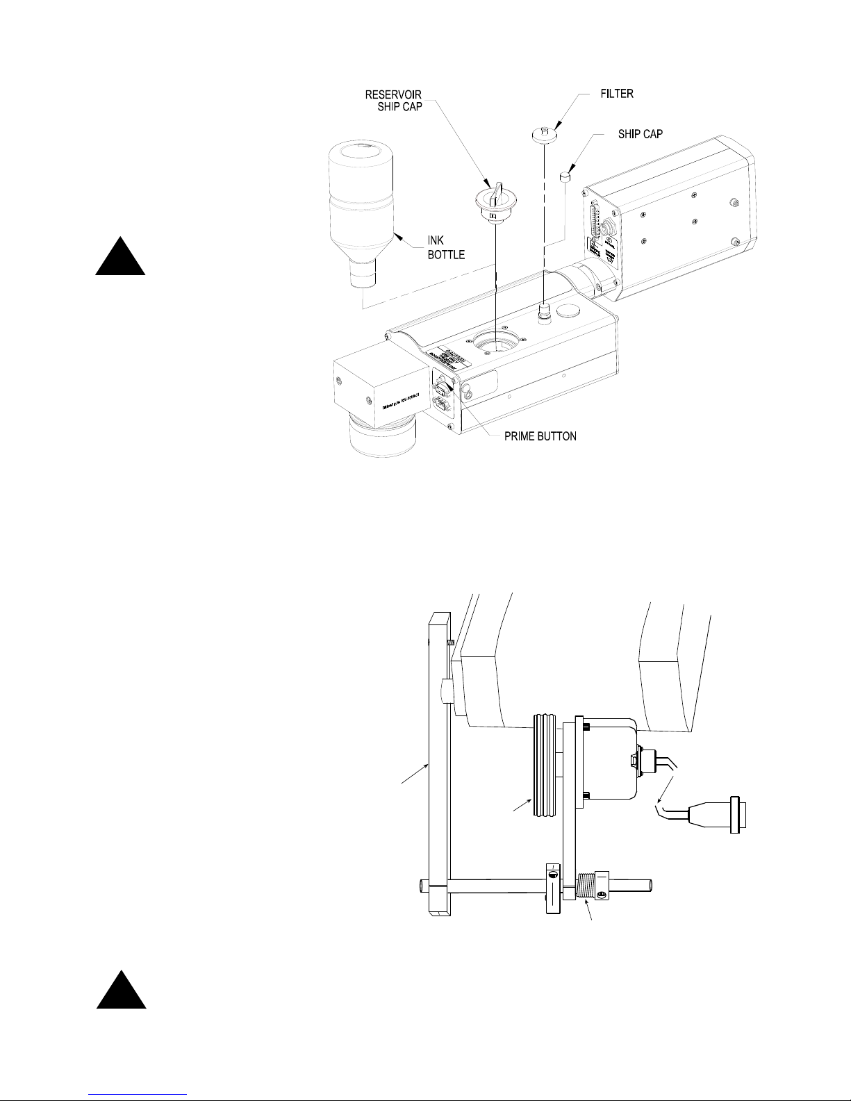
Ship Caps
CAUTION: Do not operate APS Print Heads with the Print Head Ship Cap installed! Oper-
!
ating a closed system can cause a siphoning effect which can drain the ink supply.
384e/768e Print Heads
Loosen the two thumbscrews
and remove the Ship Cap.
(See illustration at right.)
NOTE: If you place the Print Head Ship Cap on a hot print head and do not fasten it
securely, the print head will weep ink until the head has cooled down.
NOTE: Ink may accumulate behind the ship cap during shipping.
2465-623 User Manual Rev E Page 12
Marksman Matrix & Elite
Remove the Ship Cap
Spring
Mounting
Bracket
Encoder
Wheel
Conveyor
Out to Controller
Mounting Bracket
Shaft
Encoder
ENCODER
ASSEMBLY
and Install the Filter.
Remove the Reservoir
Ship Cap and Install
the Ink Bottle. Save
caps in a zip-lock bag
for future use.
CAUTION: Do not
over-tighten the ink
!
bottle when screwing
into the Reservoir.
Over-tightening will
damage the Reservoir.
Section 4: Installation
!
The Encoder
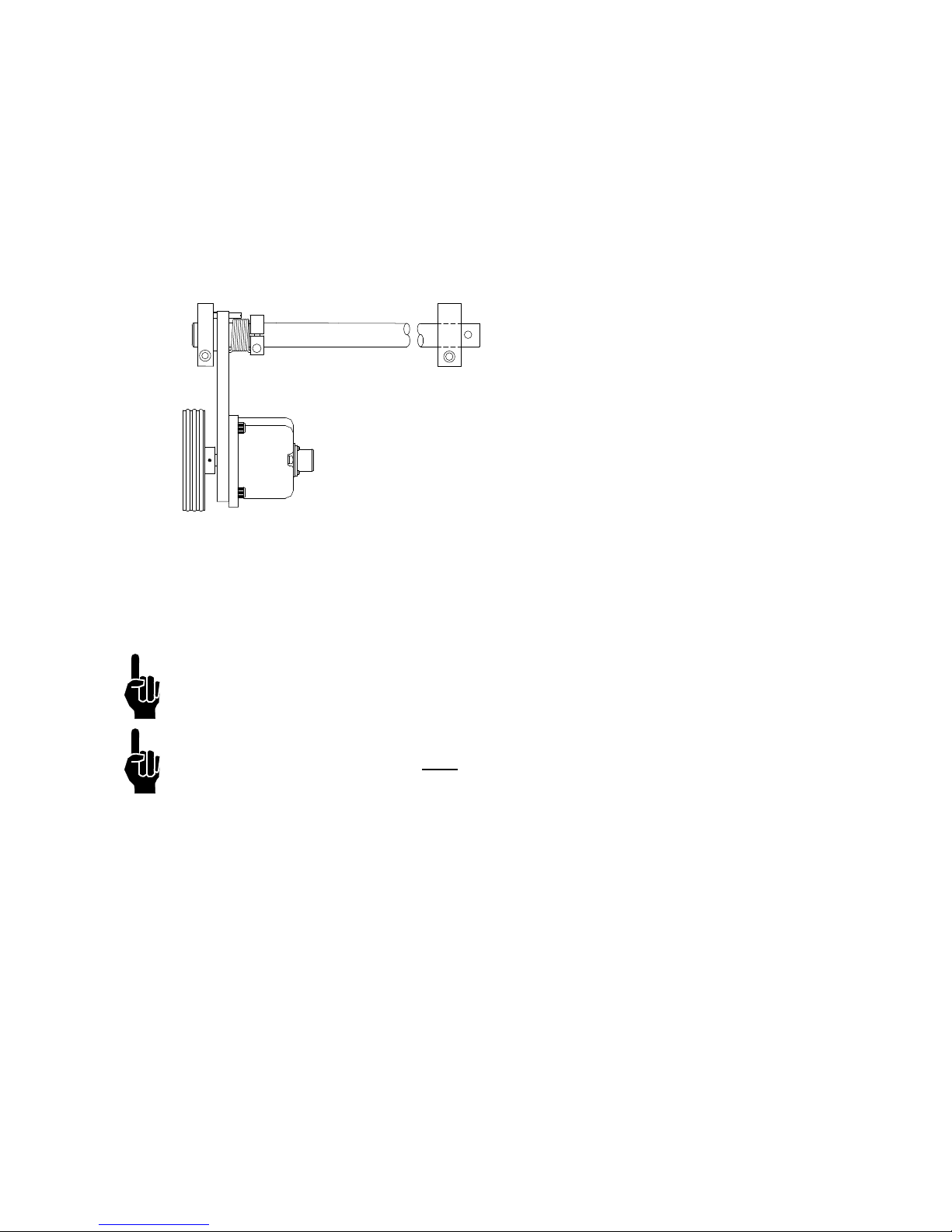
The encoder uses a wheel
that rolls against the conveyor line to track the speed.
It sends a signal to the controller, which makes adjustments for reported changes in
the line speed.
It is not necessary to install
the encoder immediately adjacent to the print heads. It is
more important to place it
where it will accurately measure the speed of the conveyor. Install it in contact with
the conveyor, or with a wheel
or roller moving the same
speed as the conveyor.
The encoder's mounting
bracket is spring-loaded.
Adjust the spring collar to
ensure that the encoder maintains stable contact with the
conveyor.
CAUTION: Do not jam the encoder wheel against the surface of the conveyor. A radial
force of over 40 lbs. will reduce the life of the bearings.
2465-623 User Manual Rev E Page 13
Marksman Matrix & Elite
PRINT
SYSTEM
PRINT HEAD CABLE
PHOTO
SENSOR
ENCODER
SYSTEM
PRINT
ALARM
BEACON
(STROBE)
MARKSMAN MATRIX OR ELITE CONTROLLER
24V
Section 4: Installation
Electrical Cable Connections
2465-623 User Manual Rev E Page 14
Marksman Matrix & Elite
Views
Bottom view of Matrix Controller
(With Optional second PHC Board
ETHERNET
LINE OUT
12 VDC
USB
VGA
DVI-D
COM 1 STROBECOM 2 ENCODER
1
2
OUTPUT TO
PRINTHEAD
4
3
PRINT HEAD CARDS
Bottom view of Elite Controller
Back view of Print System
Section 4: Installation
2465-623 User Manual Rev E Page 15
Section 4: Installation
Marksman Matrix & Elite
Priming the Print Heads
NOTE: The system will not prime either manually or automatically if there is a low ink indi-
cation. Low ink indication is caused by either low ink in the reservoir or full ink in the waste
collection bottle.
Manual Prime
NOTE: Place a wipe in front of the maintenance plate to catch excessive ink.
A manual prime can be accomplished by depressing the push-button switch on the rear of
the ink system housing. Pressing and holding the button for longer than one second will
start the pump for a manual prime. It will continue to run as long as the button is depressed,
or up to five seconds. If additional priming is required, release and press the button again.
Pressing for less than 0.5 seconds will initiate a maintenance cycle. If the system has
started a maintenance cycle and the button is pressed, the manual prime will not operate.
(The Priming Sequence and the Vacuum Cycle are less than 10 seconds long.)
APS Cycle
The APS (Automatic Priming System) cycle is a means for re-priming channels in the head
if some are missing. The APS system does this by using a priming pump to force ink out of
the channels and a vacuum pump and collection bottle to collect the ink waste. The APS
cycle can be manually started by momentarily pressing the prime button.
NOTE: The system may not print during an APS cycle or manual prime.
2465-623 User Manual Rev E Page 16
Section 4: Installation
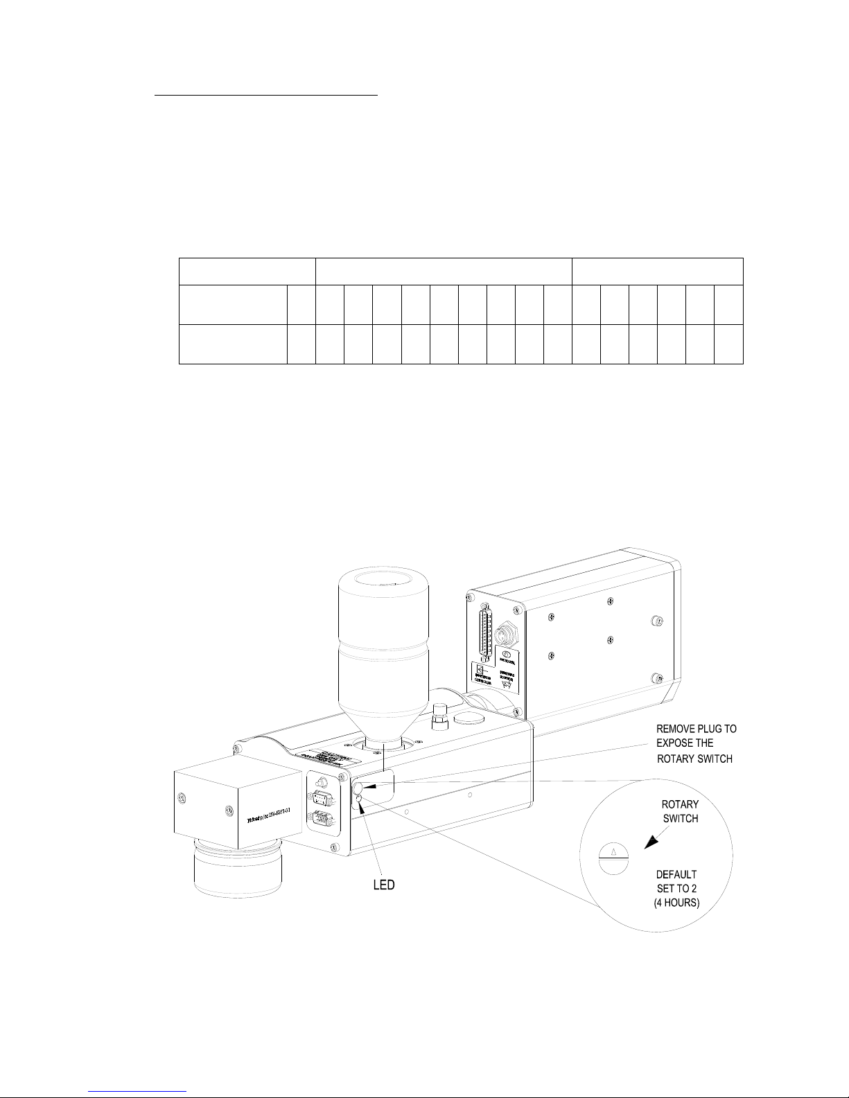
Marksman Matrix & Elite
0= No APS
UJII Heads Graphics Heads
Switch
Setting
0 1 2 3 4 5 6 7 8 9 A B C D E F
Interval
(Hours)
0 2 4 6 8 10 12 14 16 18 1 2 4 6 8 12
Timing Interval Settings
0
1
2
3
4
5
6
7
8
9
A
B
C
F
E
D
APS View for Printheads
Print Head Control of APS
Print Head control of the APS (Automatic Priming System) cycle is accomplished by a programmed timing interval set by the user at the print head (each head, if more then one is
used). It can be set to run as often as necessary, from once every 2 hours to once every 18
hours for the UJII heads; or from once every hour to once every 12 hours for the graphic
heads. The default setting is once every 4 hours (Switch Setting 2 for a UJII head or Switch
Setting C for a graphics head). The interval can be adjusted by means of a rotary switch
(Programmable Timer) mounted on the APS Controller PCB. (See the illustration below.)
See the following Table for the hour interval for each setting of programmable timer.
The priming sequence will perform three separate consecutive primes of approximately
four milliseconds each. The required time for the priming sequence is less than five seconds, with an additional 20 seconds for the vacuum cycle. As with pervious Trident printheads, printing cannot occur during the priming sequence.
2465-623 User Manual Rev E Page 17

Section 4: Installation
Marksman Matrix & Elite
Auxiliary Photocell Input
NOTE: The APS Control Cable and Auxiliary Photocell cannot be used together.
An Auxiliary Photocell input is available to insure a print cycle is not missed during the
automatic priming sequence. Connecting the Auxiliary Photocell will retard a prime
sequence until there is enough time to complete the sequence without missing a print
cycle. The default delay setting is three (3) seconds after the product passes the photocell.
Multiple heads can share the Auxiliary Photocell by using the Photocell "Y" Cable. To
change the default setting, perform the following steps:
1. Insure that the rotary switch is not in the "0" position.
2. Place a box in front of the photocell.
3. While the photocell is on, set the rotary switch to 0.
4. When the LED stays illuminated continuously, set the rotary switch to a new number (1
through F) representing the number of seconds (1 through 15) you want to delay.
"0" is not an available user setting.
5. Press and hold the Prime button until the LED starts flashing.
6. Release the Prime button.
7. Remove the box from in front of the photocell.
8. Set the rotary switch back to the desired hour setting.
Note:
2465-623 User Manual Rev E Page 18
Marksman Matrix & Elite
Section 5: Getting Started
Matrix Version
Elite Version
Matrix keyboard: The keyboard is
called when an input field is selected or
used data is required.
To Windows
Special Function
To change the
key-board language.
Matrix Keyboard
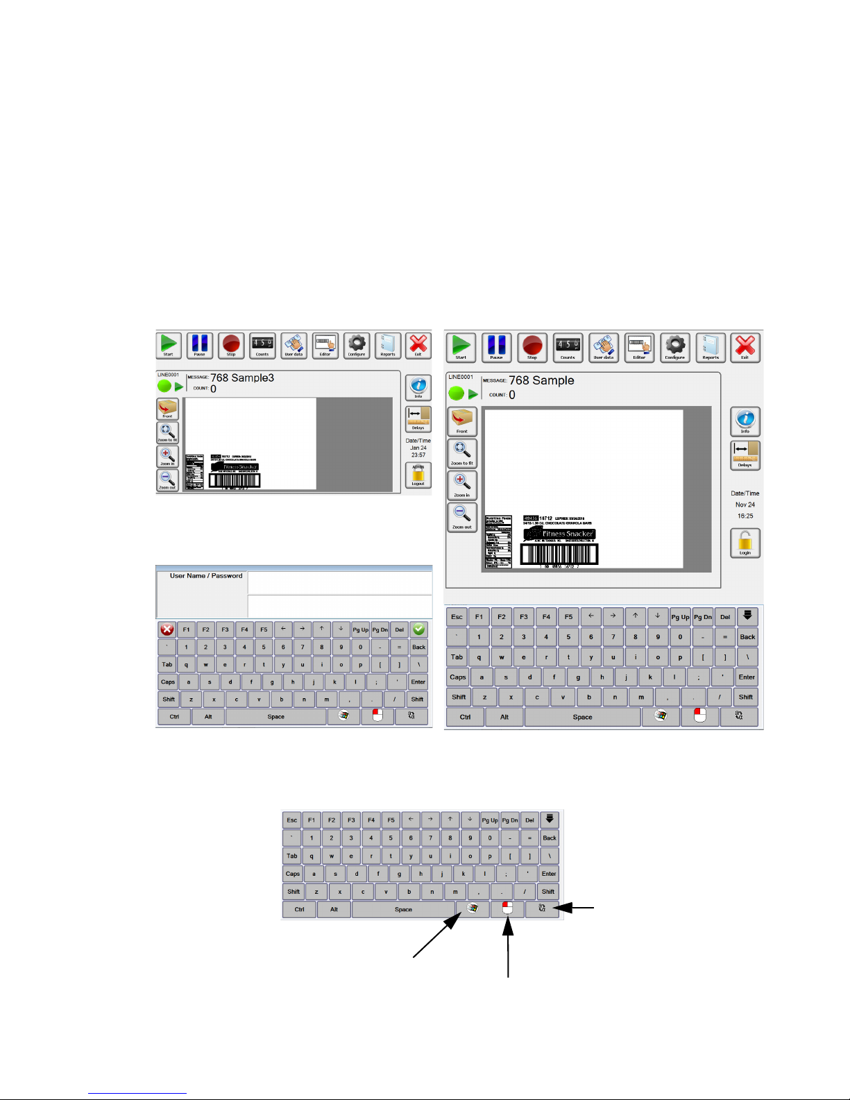
The Marksman Matrix and Elite controllers are standalone units capable of operating one to four printheads, with the addition of an optional controller card. The software has an ICON user interface for is message selection. The main difference
between the two controllers is the size and the resolution of the displays. The resolutions are 1024 x 1280 for the Elite and 1024 x 600 for the Matrix. The extra room
on the Elite display allows for the software keyboard to be accessible at all time.
To get to the keyboard on the Matrix, simply select a field that requires keyboard
input and it will appear. The main dialogs for the print control application (BoxWriter) is shown below:
Section 5: Getting Started
2465-623 User Manual Rev E Page 19
Marksman Matrix & Elite
Login
Before Login, Matrix
Before Login, Elite
Default Username and Password:
Username: Admin
Password: FOXJET
(not case sensitive)
Section 5: Getting Started
Select the Login ICON. The following screen will appear for the Matrix. Enter a username
then tab to the next field, enter a password then select the Enter button or the green check
mark. Once logged in the users account will display on the lock.
Note: User names and passwords are not case sensitive.
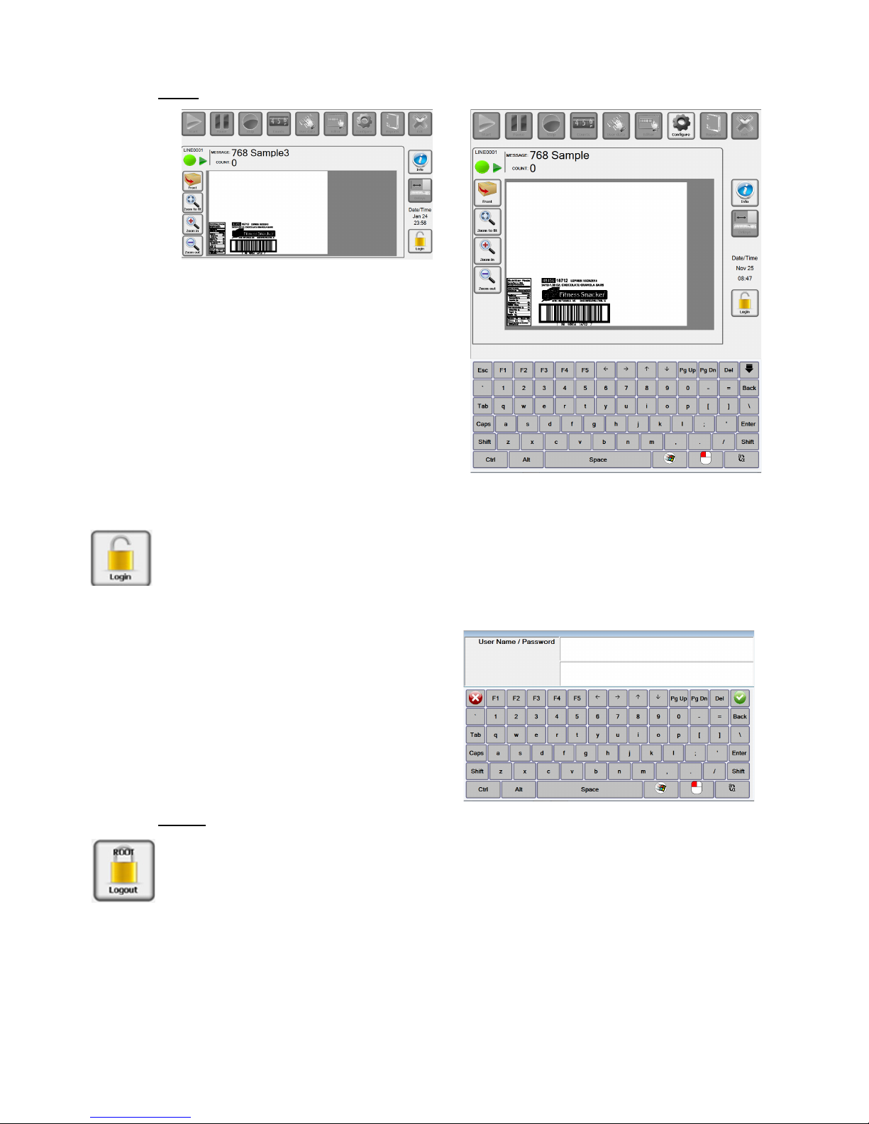
Logout
Each user should log out of the Marksman© Elite application to enforce the security restrictions. The user may log by selecting the closed padlock icon from the main display. The
system will continue operating in its current state. All menu options are disabled after the
user logs out, with the exception of the Login, Preview options and Info.
2465-623 User Manual Rev E Page 20

Section 5: Getting Started
Marksman Matrix & Elite
Start or Stop Message.
Pause or Resume message being printed.
Change the variable data that is being printed.
Start the Editor that can be used to create or change
messages.
Access to configure the system. See Configure section.
Change the count being printed, if the message contains a count element.
Access to the Printer report and Scan report.
Close BoxWriter to enter Windows desk top.
ICON’s to toggle between info window and Preview
window.
Easy access to the print head’s photocell delay.
Control of preview window and update preview data.
2465-623 User Manual Rev E Page 21
Section 5: Getting Started
Marksman Matrix & Elite
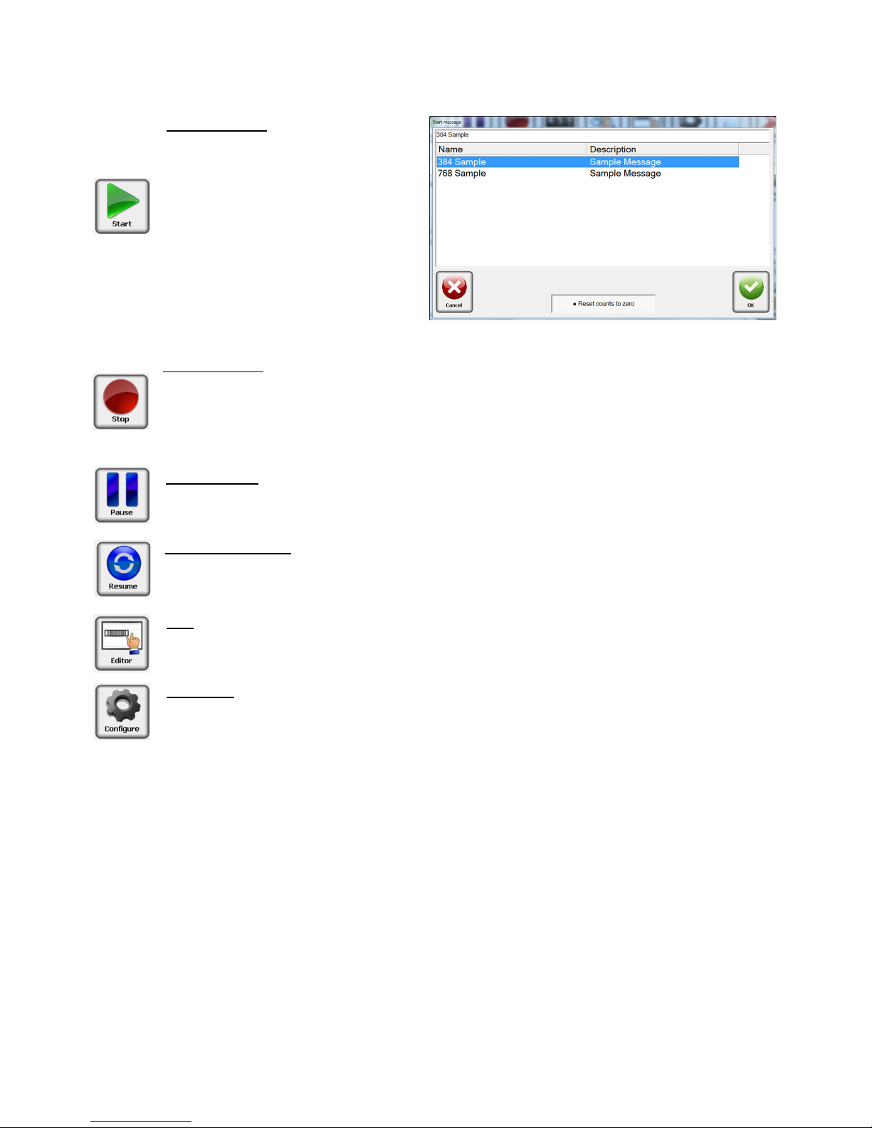
Start Message
The start message is used to ready
the system to print a label or image
that was created with the BoxWriter
Editor.
Select the desired message from the
list, or enter the message name, and
press the OK button.
Reset counts to zero: This allows the
count value to accumulate if needed
or to be reset with the start of the
message.
Stop Message
Stopping a message halts all printing related to the selected production line. The product
count is reset to zero.
The Stop message icon may be selected from the tool bar to stop the task on the
selected production line.
Idle Message
The Idle message option causes the printing to pause on the selected production line.
The product counts are halted until the current message is Resumed
Resume Message
The Resume message option causes the printing to resume on the selected production
line. The product counts are restored from the previously idled message.
Edit
The Edit menu option launches the Marksman BoxWriter Editor application. The user
must have the required rights to use this feature.
Configure
The Configure icon allows access to other options, Print Test Pattern, Database Start,
Print Heads, Production line, System, Security, Help.
See the Configure section in the manual for additional information.
2465-623 User Manual Rev E Page 22
Marksman Matrix & Elite
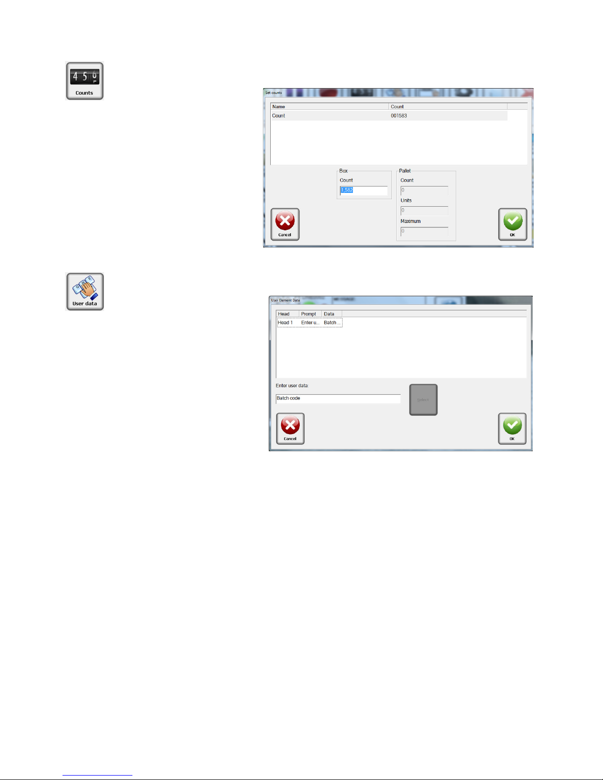
Counts
Count is the current number
of the box in the pallet
series. It is always listed as
the "last printed" box. To
change the Count value,
enter the current box count
value. Enter a
0 to print a
count of 1 on the next box.
User data or User elements
may only be changed if the
message is loaded. The message must contain user elements and be "Running" or
"Idle" in order to modify the
user data.
Select the
User data ICON.
Edit the data in the lower edit
box and press
OK to save
changes. For multiple elements, make all data changes
before pressing
OK to save
changes. Press
Cancel to exit
without saving changes.
User Data
Section 5: Getting Started
2465-623 User Manual Rev E Page 23
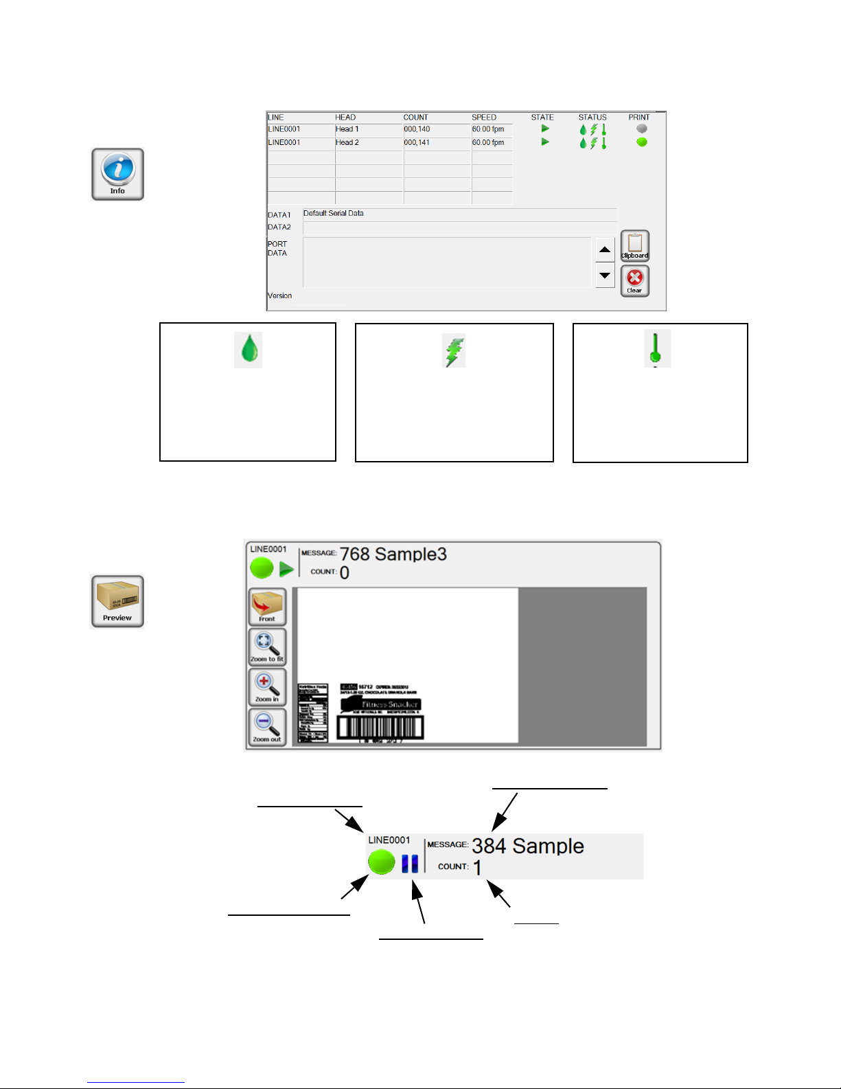
Section 5: Getting Started
Marksman Matrix & Elite
Print Head Ink level or
Ink Collection bottle
Green = Good
Yellow = Low
Red = Out
Print Head High Voltage
Green = Good
Red = Low
Print Head Temperature
Green = Good
Red = Low
NOTE: The system will not print if the controller is reporting a Low Voltage Error, Out of
Ink condition or Low Temperature condition. If a strobe is connected to the system, this
is represented by a flashing red light.
Current Message
Count:
Next count to be printed
Production Line
Print Head Status:
Green: Ok
Yellow: Low Ink
Red: System Printing Error
Message State:
Printing
Stopped
2465-623 User Manual Rev E Page 24
Marksman Matrix & Elite
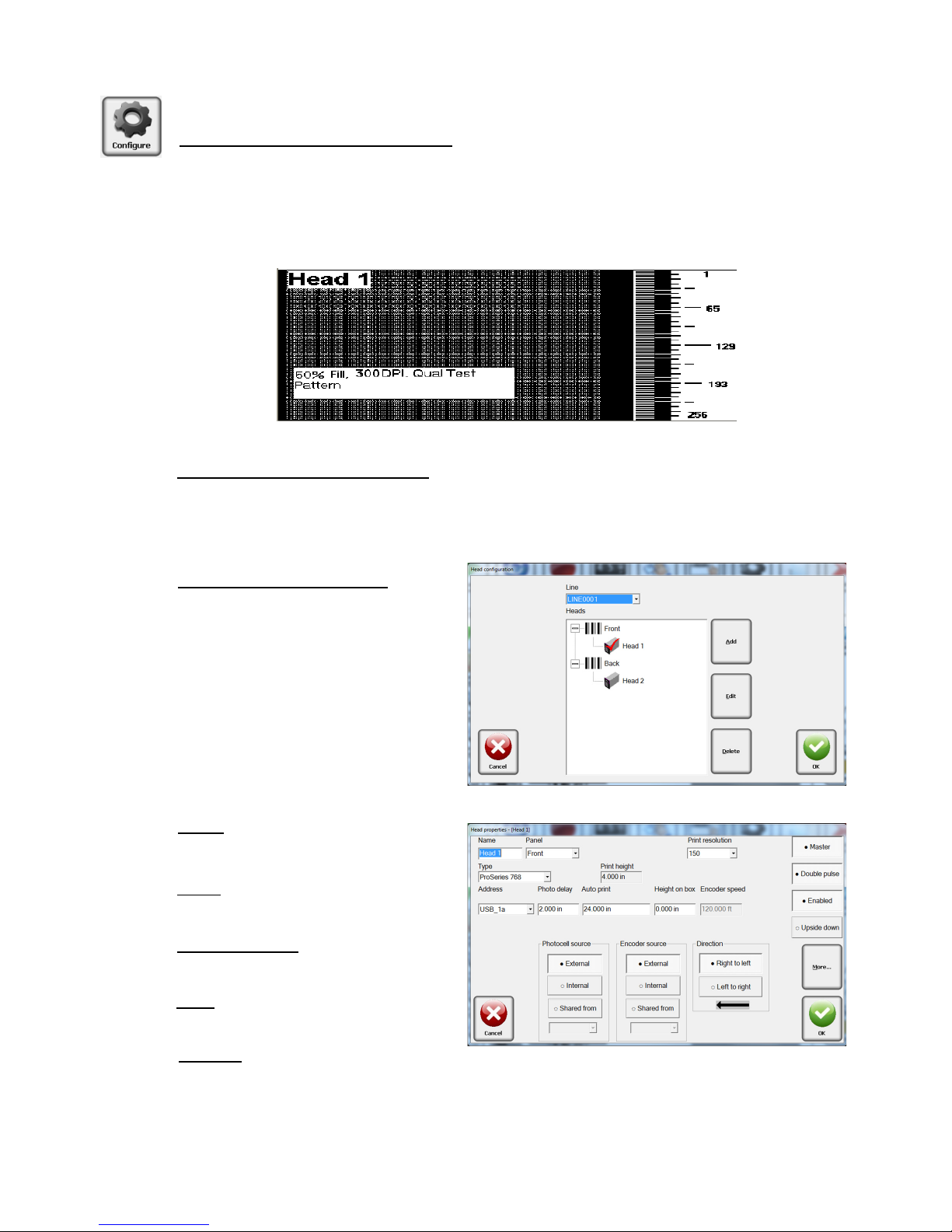
Configure, Print Head:
Configure, Print Test Pattern
This function is designed to exercise every channel of the print head to verify all are
printing properly.
When the user clicks the “Test Pattern” button, a test image is generated. Each head on
the currently selected line will print this pattern (along with the print head’s name). In the
example below, the Test Pattern is from Head 1.
Configure, Database Start
Set a message based on data that is located in a database. The database must be setup
before the option is available.
Refer to Appendix F: Database Start
Configure, Print Head
Select Configure, then select Print
Heads from the menu. Select a
panel and click on a head. A head
may be added or removed by
clicking the appropriate Add/
Remove button. To edit a head,
select it and click Edit; or double
click it.
Name: The head’s
user-defined name.
Panel
: The panel which the head
will print on.
Print Resolution
: 150, 200 and 300
dots per inch (dpi).
Type
: Select a head type from the
drop-down menu list.
Address
:
Each card is assigned two heads: 1a and 1b, or 2a and 2b. The cards have jumpers
to determine which card it is. The bottom connector of the card is always the designated as “a”.
Section 5: Getting Started
2465-623 User Manual Rev E Page 25

Section 5: Getting Started
Marksman Matrix & Elite
Photo delay: Photo delay is the horizontal distance (in inches) measured from the photocell to the head.
Auto print inches
: If internal photocell is selected, this number indicates the length of the
message to be printed. For example, if it is set to 36, the internal photocell will fire once
for every 36 inches of travel of the conveyor, as indicated by the encoder. The accrual
photocell must be tripped for this to work.
Height on box
: The vertical distance in inches measured form the lower part of the prod-
uct or conveyor to the print head nozzle zero.
Encoder Speed
: The desired internal encoder speed measured in feet per minute. The
default is 60 feet/min
Photocell source
: Indicates whether the photocell is external or internal. The photocell
signal from another head may also be used (shared).
Encoder source:
Indicates whether the encoder is external or internal. The encoder sig-
nal from another head may also be used (shared).
Direction
: The direction of travel of the product may be right-to-left or left-to-right, as
viewed from behind the print head.
Master
: Each line must have a master head. The master print head receives/distributes
the signals for the photocell and encoder to the remaining heads. The master head is
also used to determine count values.
Double pulse
: Creates a darker print generally needed for the ProSeries 768e and 384e.
Enable
: Activates the card and errors
Upside Down
: Used to print the entire image upside down.
More
Linked to: Ties the information to be printed to additional heads. If the information is the
same on multiple sides of the box, link the heads together and the image is automatically
placed on the other head.
2465-623 User Manual Rev E Page 26

Marksman Matrix & Elite
Configure, Production Line
The production line configuration
allows for grouping of settings that
relate to a particular setup. Select
Configure, then Production Line
form the menu. To edit a line, select
it and click
Edit; or double click the
line.
Add
: The Add button allows for the
addition of another production line,
for a maximum of two production
lines.
Delete
: The Delete button allows for the removal of a production line form the
configuration. All messages created for the production line will be deleted.
Description
: The description field is used to help define the production line.
Coupled
: If this field is checked, starting a message on one line will also start in on the
other. The same is true for Stop, Idle and Resume. Note that you must have a two lines
configured to use this feature.
This group defines the parameters
for a fixed scanner that may be
connected to the Controller, The
data is stored under the Scan
Report (see
Reports, Scan Report).
No Read String
: The No Read
String must match the No Read
string that is transmitted by a fixed
scanner. The printing will be
stopped upon reaching the maximum value.
Consecutive No Reads
: The consecutive No Reads field is used to preform a quality
check on barcodes that are printed, This value determines the maximum number of
consecutive No Reads that may be transmitted by a fixed scanner. The printing will be
stropped upon reaching the maximum value.
Serial Download Port:
Please select the port to be used to send the data out if it is
required to be transmitted to a device at the start of each task. The data is entered
through the Editor Task properties.
Reset on Task Start
: The Reset on Task start check box determines that the current
number of consecutive No Reads will be reset to zero upon a message start.
Buffer Offset
: The Buffer Offset value determines the number of characters to offset into
the buffer as transmitted by the hand scanner.
Data Length
: The Data Length value determines the number of characters to extract from
the data buffer that will form a task name.
Section 5: Getting Started
Configure, Fixed Scanner
2465-623 User Manual Rev E Page 27

Marksman Matrix & Elite
Configure, System
General Setting– Windows
Ports
Used to configure the system
COM ports, that may be used for
variable data or stating a message.
Serial Port
: Select the appropriate
button to edit the setup
parameters for a serial port on the
Matrix or Elite.
Each of the properties may be
selected using the corresponding
drop-down menu choices. When
selections are complete, click
Apply. The default selections are
shown in the screen at the right.
Baud
: The Baud option
determines the speed of the
transferred data and may be set
to 9600, 19200, 38400, 57600 or
115200.
Parity
: Parity determines the type
of parity bit to be used. It may be
set to None, Odd, or Even.
Data Bits: Data Bits determines
the number of data bits used. It may be set to 7 or 8.
Stop Bits
: Stop Bits determines the number of stop bits to be used. It may be set to 1, 1.5
or 2.
Device Type:
Task Start- Serial device used to select/start a message, generally a hand scanner.
Database task start
– Serial device used to search s database for message start.
Barcode Verification
– Fixed scanner used to read each barcode after it is printed.
Varia ble Data
– Data to be printed imported through the serial port
Host interface
– Remote control of the Controller through the serial port.
General Setting– Startup
To restart the message that was running if power is lost or the system was shut down,
check the “Automatically restart last task” box. (This box is checked by default.)
Remember user data: The data will be retained until new data is entered even if the
software is reset.
Remember serial data: The data will be retained until new data is sent even if the software is reset.
General Setting– Counts
Continuous Count: Select this feature to cause the Count on the main screen never reset
to zero at the start of a new message.
Section 5: Getting Started
2465-623 User Manual Rev E Page 28

Marksman Matrix & Elite
General Setting - Time:
The main screen Time and Date
field format is defined in this window.
There are three user controlled date
and time fields that can be
formatted.
Suppress time change warnings:
Used to disable software warnings of
any Windows time changes.
Current time: Windows system time
Users
The security feature of the
Marksman Matrix & Elite
Series allows the system
administrator to configure
users and access rights.
Add
: Select the Add button
to create a user account.
Remove
: Select the
Remove button to delete a
user account.
Properties
: Select the
Properties button to modify
or view the user account
information.
Firstname
: Enter the user’s
first name in this edit box.
Lastname
: Enter the user’s
last name in this edit box.
Username
: Enter the user’s
first name in this edit box.
Configure, Security:
Section 5: Getting Started
2465-623 User Manual Rev E Page 29

Section 5: Getting Started
Marksman Matrix & Elite
Security groups allow the administrator to assign similar users with a specific set of
access rights. Select Security, then Group Options from the menu. Ten configurable
security groups are available. A user must be assigned to one group. Group names may
be modified to better describe the access level. Select a Group, then select or unselect
Options. Click OK to accept changes and close the screen.
The default access rights for each security group are shown in the following table:
Security Group/Option Access
Table
Operator
Manager
Level 3
Graphics Dept.
Supervisor
Level 6
Level 7
Level 8
Level 9
Administrator
Output Table X
Configure Print Head Settings X X X X X
Start Message
X
X X
Stop Message
X
X X X X
Place System in Test Mode X
Run Editor X
Configure Pr oduction Lines X X X X
Configure Users X
Configure Security Options X
View/Clear Scanne r Report X
View/Clear Scanne r Report X
Translate the software X
Configure general Windows X
Exit Application X
Configure task start database X
Configure serial data format X
Configure the strobe X
Import X
Export X
Group Options:
2465-623 User Manual Rev E Page 30

Section 5: Getting Started
Marksman Matrix & Elite
To import all tasks that
were previously exported,
choose
File, then Import.
In the “filename” field, input
the name of the file (full
path) the exported tasks
were saved to; or browse
for the file by clicking the
Browse button.
If there is data on the controller that the user wants
to back-up, click
Yes on
the Export option.
To export all existing tasks,
choose
File, then Export.
Input the name of the file to
export to, or browse for an
existing file by clicking the
Browse button. Click the
Export button. If the file
already exists, the user will
be prompted to overwrite
the file or cancel the
request.
If successful, a confirmation
message will appear.
About
Components
A list of the .dll that are installed and the version number.
Cmd line args
A list of the software options that are turned on.
Firmware
A list of the Gate Array version number of the Print Head controller cards.
Translate
Select the desired language to be converted to. When the files have been translated, the
application will be re-started in the desired language.
Configure, Import:
NOTE: It is recommended that all printing tasks be stopped until the Import function has
been successfully completed; and that the current database be exported for backup purposes.
Configure, Export:
NOTE: It is recommended that all printing tasks be stopped until the Export function
has been successfully completed.
Configure, Help:
2465-623 User Manual Rev E Page 31

Section 5: Getting Started
Marksman Matrix & Elite
Scan reports
The Scan Report contains information relating to the current task and scan results of a
printed barcode. The scan results are received through the RS232 port from a barcode
scanner properly. configured and connected to the Marksman© controller.
Date:
Date is the date the scan event occurred.
Line:
Line is the production line that the scan event occurred on.
Message:
Message is the name of the message operating while the scan event occurred.
Barcode:
Barcode is the barcode data scanned and received. The contents of this field
may contain the words NO READ if the barcode could not be decoded.
Total:
Total number of decode attempts, including successful and failed decodes.
Good:
Good indicates the number of successful decodes of the scanned barcode.
Export:
Export allows the information to be saved in a comma delimiter format so it can
be used in other software applications.
Enabled:
Allows for the collection of data.
Auto Export at Task Start:
Exports an entry to text file defined by export path.
Print reports
The Print Report contains historical information regarding the printing operation. The print
report is a table named
reports within a Microsoft® Access® Database named Marks-
man Elite. Click on
Reports then select Printer Report from the menu.
Time:
Date and time that the
action occurred.
Action:
The event such as Start or
Stop Message.
User:
The User who was logged
in at the time the action
occurred.
Counts:
Counts is the product count
of the task for which the
action applies.
Line:
The production line that the information is for.
Message:
The name of the message for which the action applies.
Export:
Export allows the information to be saved in a comma delimiter format so it can be used
in other software applications.
Auto Export at Task Start:
Exports an entry to text file defined by export path.
Enabled:
Allows for the collection of data.
Reports
2465-623 User Manual Rev E Page 32

Marksman Matrix & Elite
Delays
This feature allows the operator to make changes to
where the print starts, or
change the photocell delay.
These changes are not permanent and only last until
another message is selected.
This may be useful do to variations in the location of preprinted information on the
box.
NOTE:
Changes made using the Delay ICON are only temporary or until another message is
started. Permanent changes to the photocell delays must be done thru the Configuration.
To make changes, Select the
desired head, use the arrow
buttons to decrease or increase
the delay value.
Use the
Apply button to
implement the changes.
The incremental value can be
changed by selecting the field.
Select
OK when complete.
To Decrease
delay
To Increase
Delay
Incremental Value
Section 5: Getting Started
Exit
This will close down the all printing operation and exit out of BoxWriter software. Only operators with proper security rights can Exit the software.
2465-623 User Manual Rev E Page 33

Section 6: BoxWriter© Matrix & Elite Editor
Marksman Matrix & Elite
Section 6: BoxWriter© Matrix & Elite Editor
Define
Boxes
To define boxes, select Define
> Boxes
.
To add a new box, click
Enter the length, width, height
and name. The length, width
and height fields must be
between 1 and 40 inches. The
description field is optional.
To edit an existing box, select it
and click
the item.
To delete an existing box,
select it and click
ple boxes can be selected by
using the shift and/or control
keys. Boxes that are currently
in use in a task cannot be
deleted. The task’s box property must be changed before
the box can be deleted here.
Edit, or double-click
Delete. Multi-
Add.
Pre-printed information can be
added to the box to give the
operator a true representation
of how the box will look as it is
being printed on.
Add: Allows the operator to
assign a .bmp or .jpg file to a
panel on the box.
Edit: Allows the operator to
change which .bmp or .jpg file
is assigned to a panel of the
box.
Delete: Will remove the file
from the panel.
2465-623 User Manual Rev E Page 34

Marksman Matrix & Elite
Box Usage
To define box usage, select
Define > Box usage.
If it is desirable to restrict a
box from a given line, it can
be done here. By default, all
new boxes are available on
all lines. To restrict it, select
the line, then select the box.
It can then be moved to the
"restricted" list by clicking
the "<" key. Clicking the
"<<" moves all boxes for a
given line to the restricted
list, regardless of selection.
Conversely, the ">" and
">>" keys move boxes to
the "available" list.
Section 6: BoxWriter© Matrix & Elite Editor
Editor Defaults
To define editor defaults, select Define > Editor
defaults
This dialog controls the editor's display units.
The "Resize handle size" field is used by re-sizable elements (such as a Bitmap element). Valid
values range from 5 to 15. Larger values make it
easier to perform a resize operation on a touch
screen.
In the example at right, the eight squares
around the perimeter are the resize handles.
.
Checking the "Warn if elements overlap" box will warn
the user when element fields overlap in a message.
2465-623 User Manual Rev E Page 35

Marksman Matrix & Elite
Element Defaults
To define element defaults, select
Define > Element defaults. To
change the defaults, select an element type and click
double-click the item.
The elements listed here define
how new elements are created.
(For a description of the individual
elements, refer to the
section of this manual.)
Properties, or
Elements
Section 6: BoxWriter© Matrix & Elite Editor
To change the font, click
Change button. The
the
dialog at right is used to
change the default font
parameters.
The Font drop-down box
will display a list of all
TrueType fonts installed
on the system.
The Size field refers to
the height of the font in
pixels.
Average width defines
the average character
width (in pixels). A value
of 0 means that the system will use the font's
default widths.
Backup Path
A backup of the Marksman Matrix & Elite database is stored in a backup location every
time the application is closed. The path directs where the file is saved.
2465-623 User Manual Rev E Page 36

Marksman Matrix & Elite
Custom Date/Time Formats
To define date/time settings, select
tom date/time formats
The date/time settings
shown here are used by
Date/time and Expiration
date elements.
To create a new custom
format, click
To delete an existing custom format, select it and
click
Delete. Multiple codes
can be selected by using
the shift and/or control
keys.
Define > Cus-
.
Add.
Section 6: BoxWriter© Matrix & Elite Editor
To edit an existing custom code, select it and click
time format dialog is shown below.
The "Format string" contains a user-defined string consisting of format specifiers.
Edit, or double-click it. The Build date/
The "Sample" field shows a sample of the current Format string.
Valid format specifiers are listed at the bottom of the dialog. To insert them in the current
string, select them and click
2465-623 User Manual Rev E Page 37
Insert (or double-click).

Section 6: BoxWriter© Matrix & Elite Editor
Marksman Matrix & Elite
Possible format specifiers are listed in the following table:
Specifier Meaning
%a Abbreviated weekday name
%A Full weekday name
%b Abbreviated month name
%B Full month name
%c Date and time representation appropriate for locale
%d Day of month as decimal number (01 - 31)
%%D Day of month as decimal number (arbitrary length)
%%-D Day of month as decimal number, left justified (arbitrary length)
%#d Day of month as decimal number; no leading zero (1-31)
%H Hour in 24-hour format, with leading zero (00 - 23)
%#H Hour in 24-hour format; no leading zero (0-23)
%H:%M:%S Hour: Minute: Second in 24-hour format, with leading zero on the hour
(00-23)
%#H:%M:%S Hour: Minute: Second in 24-hour format, no leading zero on the hour (0-
23)
%I Hour in 12-hour format (01 - 12)
%#I Hour in 12-hour format; no leading zero (1-12)
%I:%M:%S Hour: Minute: Second in 12-hour format; with leading zero on the hour
(1-12)
%#I:%M:%S Hour: Minute: Second in 12-hour format; no leading zero on the hour (1-
12)
%j Day of year as decimal number (001 - 366)
%m Month as decimal number (01 - 12)
%M Minute as decimal number (00 - 59)
%%M Month as decimal number (arbitrary length)
%%-M Month as decimal number, left justified (arbitrary length)
%p Current locale’s AM/PM indicator for 12-hour clock
%S Second as decimal number (00 - 59)
%U Week of year as decimal number, with Sunday as first day of week (00 -
53)
%w Weekday as decimal number (0 - 6; Sunday is 0)
2465-623 User Manual Rev E Page 38

Section 6: BoxWriter© Matrix & Elite Editor
Marksman Matrix & Elite
%W Week of year as decimal number, with Monday as first day of week (00 -
53)
%x Date representation for current locale
%X Time representation for current locale
%y Year without century, as decimal number (00 - 99)
%Y Year with century, as decimal number
%%Y Year as decimal number (arbitrary length)
Examples:
"%%YYYY" is formatted as "2004"
"%%YY" is formatted as "04"
"%%Y" is formatted as "4"
%%-Y Year as decimal number, left justified (arbitrary length)
%z; %Z Time zone name or abbreviation; no characters if time zone is unknown
%% Percent sign
%%0H Hour Code
%%0M Month Code
%%0A Day Code
%%0Q Quarter Hour Code
NOTE: The # flag may prefix any format specifier. In that case the meaning of the format
code is changed as follows:
%#a, %#A,
%#b, %#B,
%#p, %#X,
%#z, %#Z,
%#%
%#c Long date and time representation, appropriate for current locale. For
%#x Long date representation, appropriate to current locale. For example:
%#d, %#H,
%#I, %#j,
%#m, %#M,
%#S, %#U,
%#w, %#W,
%#y, %#Y
# flag is ignored
example: "Tuesday, March 14, 1995, 12:41:29"
"Tuesday, March 14, 1995"
Remove leading zeroes (if any)
2465-623 User Manual Rev E Page 39

Section 6: BoxWriter© Matrix & Elite Editor
Marksman Matrix & Elite
Date/Time Codes
Select Configure, System, then Date/Time Codes from the menu.
Line indicates the production
Line:
line selected.
Click on the folder tabs to access
the date/time code tables. Select an
entry in the table by clicking on the
desired row. Click on
the data for the selected table entry.
Click
OK to exit and save changes
Cancel to exit without saving
or
changes.
Edit to modify
Months:
string values that are used in date
codes for the standard months of
the year.
Hours:
twenty-four codes for the hours of
the day. The codes may be customized for special coding.
Quarter Hours
Days:
Rollover:
expiration and date codes will
change to a new value. The default
rollover value is midnight.
"Hold"
tion Date until the Roll over time.
Months represents the
The Hours table stores the
: The Quarter Hours’ table stores codes for 15 minute intervals.
The day table holds the value to be used for the appropriate day.
The time at which the
: Holds the Date or Expira-
2465-623 User Manual Rev E Page 40

Marksman Matrix & Elite
Bitmap Editor
To define bitmap settings, select
Bitmap settings
The "Bitmap editor"
field defines the program used to edit bitmaps. By default, it is
Microsoft® Paint. To
change it, browse
and select the program to be used.
Define >
.
Section 6: BoxWriter© Matrix & Elite Editor
Label Editor
Used to configure software when the Marksman Matrix or Elite is used with a Label Applicator.
Shift Codes
To define shift codes, select
Define > Shift codes. Shift
codes are used by Shift elements.
The shift code’s length must be
from 1 to 15 characters. The
code’s times must be in order
from least to greatest (i.e., code
1 cannot be later than code 2 or
3).
This determines the pro-
Line:
duction line for the shift code
definitions.
Select the appropriate production line. Enter the shift start times and any user-defined
codes. The shift start times must be entered in 24-hour format. The shift code may contain
a maximum of 15 alphanumeric characters.
The sample dialog shows shift 1 starting at 7:00 AM, shift 2 starting at 3:00 PM and shift 3
starting at 11:00 PM.
2465-623 User Manual Rev E Page 41

Section 6: BoxWriter© Matrix & Elite Editor
Marksman Matrix & Elite
Sub-Elements
To define fonts, select Define > Sub-elements.
Sub-elements can be used by certain barcodes (see the
usage). The Sub-elements dialog is shown below.
To create a new sub-element, click the "
To delete an existing sub-element, select it and click the "
+" button.
Barcode section of the manual for
X" button.
To edit an existing sub-element, select it and click the
most button). The Sub-element properties dialog is shown below.
The "ID" field identifies the sub-element.
Properties button (the bottom, left-
2465-623 User Manual Rev E Page 42

Section 6: BoxWriter© Matrix & Elite Editor
Marksman Matrix & Elite
The "Element type" field defines the type of element. The following types are supported by
sub-elements:
•Text
• Count
• Date / time
• Expiration date
•Shift
•User
• Serial data
To change the element's default values, click the
tion of the manual for examples of property dialogs for element types.
The "Description" field is used for a long-hand description of the sub-element.
The "Data" field contains the default data for the sub-element. Note that the Data must satisfy the Input mask.
The Input mask defines what kind of
data the sub-element can accept.
To change it, click the
The Build mask dialog is shown at
right.
In this example, the mask is set up
for data consisting of two digits and
up to 10 alpha-numeric characters.
Build button.
Properties button. See the Elements sec-
The buttons along the right side of the dialog are as follows, from top to bottom:
• Move up - moves the selected mask up.
• Move down - moves the selected mask down.
• Properties - displays the mask properties for editing.
• Add - creates a new mask.
• Delete - deletes the selected mask.
2465-623 User Manual Rev E Page 43

Marksman Matrix & Elite
The following is an example of the Mask
properties dialog:
• Alpha allows uppercase A to Z.
• Numeric allows 0 to 9.
• Alphanumeric allows uppercase A to Z
or 0 to 9.
• Punctuation allows characters such as
"," or ":".
• Any allows any character.
Application Identifiers
To define fonts,
select
Application
identifiers
Define >
.
Section 6: BoxWriter© Matrix & Elite Editor
Application
identifiers can
also be used by
certain barcodes. They
work in the
same manner
as sub-elements.
An example of the
Application identifier properties dialog is shown at right.
Only the "Element
type" and "Data"
fields can be
changed. See the
Sub-elements sec-
tion for descriptions
of these fields.
2465-623 User Manual Rev E Page 44

Section 6: BoxWriter© Matrix & Elite Editor
Marksman Matrix & Elite
Global Barcode Parameters
To define barcode parameters, select Define > Global Barcode Parameters.
Select the line, then select the head type. Heads with 32 channels have their own set of
barcode parameters, as do 256 channel heads.
To view or edit a set of barcode parameters, select it then click
item.
NOTES:
Only the custom bar and space parameters can be changed; and only a person having
advanced knowledge of barcode and inkjet printing systems should change these parameters. An unusable barcode may be printed using improper settings.
C128, C39, C93 & I 2of5
height and Ratio cannot be changed. Only custom parameters allow these fields to be
changed.
: On standard barcode parameters, the Magnification, Bar width and Space width can-
UPC
not be changed. Only custom parameters allow these fields to be changed.
: On standard barcode parameters, the Magnification, Width, Total
Edit, or double-click the
2465-623 User Manual Rev E Page 45

Marksman Matrix & Elite
An example of UPCA barcode parameters is shown at right.
The "Magnification" field is the value displayed in the Magnification field on the
Barcode element dialog.
The "Bar height" is the total height of the
symbol in pixels.
The "Bar width" and "Space width" fields
define the width, in pixels, of the symbol's
bar/space modules.
The "Font name" control will display a list
of all TrueType fonts installed on the system.
The "Font size" field refers to the height
of the font in pixels.
Section 6: BoxWriter© Matrix & Elite Editor
"Average width" defines the
average character width (in
pixels). A value of 0 means
that Windows will use the
font's default widths.
The "Magnification" field is
the value displayed in the
Magnification field on the
Barcode element dialog.
The "Total height" is the total
height of the symbol in pixels.
The "Horz. bearer" field specifies the width of the symbol's
horizontal bearer, in thousandths of an inch.
The "Vert. bearer" field specifies the width of the symbol's
vertical bearer, in thousandths of an inch.
The "Quiet zone" field specifies the width of the symbol's
quiet zone, in thousandths of an inch.
The "Font name" control will display a list of all TrueType fonts installed on the system.
The "Font" size field refers to the height of the font in pixels.
2465-623 User Manual Rev E Page 46

Section 6: BoxWriter© Matrix & Elite Editor
Marksman Matrix & Elite
Tools
Ink Usage
The ink usage generator will calculate the cost of each print and how many prints you will
get from each bottle.
Files
New
To create a new task,
choose
The user will be presented
with the dialog at right. Pick
which production line the
task is to be created for, give
it a name (and description, if
desired) and select the box it
will be printed on.
The "Task name" field must
contain only letters and numbers; no spaces or special
characters are allowed. The
maximum number of characters is 32.
File > New.
2465-623 User Manual Rev E Page 47

Section 6: BoxWriter© Matrix & Elite Editor
Marksman Matrix & Elite
Creating a Task
The next step is to insert elements into the label to be printed. The box is shown with highlighted areas showing where heads have been placed on the box. The printing areas cannot be changed from the editor because the information about the heads and their
relationship to the box comes from the system configuration, which is limited by physical
devices installed. Different panels can be selected to add elements to the task. Once a
head has been chosen, select an element to be placed on the box. The process is
repeated until all the desired information needed on all sides of the box are completed. The
next step would be to save the task. (Refer to appropriate sections in this manual relating
to Elements and Saving Files.)
NOTE: If two elements overlap each other they both will show up in red. This is to let the
operator know that a problem may occur. The operator will also be told before saving the
task.
To disable the element overlap warnings, see
2465-623 User Manual Rev E Page 48
Define, Editor Defaults earlier in this section.

Marksman Matrix & Elite
Open
To open an existing task,
choose
Select the task to be opened,
and click
the task to be opened.
Checking the "Open read
only" box will open the task in
read-only mode (i.e., the user
will not be able to modify the
task).
Checking the "Show preview"
box will show a preview of the
selected task. For large
tasks, it may take several
seconds to generate the preview.
File > Open.
OK; or double-click
Section 6: BoxWriter© Matrix & Elite Editor
2465-623 User Manual Rev E Page 49

Section 6: BoxWriter© Matrix & Elite Editor
Marksman Matrix & Elite
Copy
To copy tasks from one line to another, choose File > Copy.
Select the line to copy from, then select the tasks to be copied. Checking the "All" box will
automatically select all existing tasks for the given line.
When the desired tasks are selected, click
Copy.
If successful, you will see a confirmation message similar to the one at right.
The user may change both the "To" and "From"
lines and perform the copy function multiple
times.
OK after to save the changes.
Click
2465-623 User Manual Rev E Page 50

Section 6: BoxWriter© Matrix & Elite Editor
Marksman Matrix & Elite
This function works best when both the "To" and "From" lines have identical head configurations. However, if they do not, the user may elect to configure the head mapping. To do
this, select the head to be mapped and click
The user will be presented with
the dialog at right. Select the head
to map to in the "To" field and click
OK.
Edit (or double-click).
Clicking
bring up the Head properties dialog. Note that head
properties are read-only in
the Editor.
Properties will
2465-623 User Manual Rev E Page 51

Section 6: BoxWriter© Matrix & Elite Editor
Marksman Matrix & Elite
Import
NOTE: It is recommended that all printing tasks be stopped until the Import function has
been successfully completed; and that the current database be exported for backup purposes.
To import all tasks that were previously exported, choose
Import.
then
In the "filename" field, input the
name of the file (full path) the
exported tasks were saved to; or
browse for the file by clicking the
Browse button.
File,
If there is data on the controller that the user does not want to lose, click
ing screen.
The screen at right will appear at the
completion of the Import function.
Yes on the follow-
2465-623 User Manual Rev E Page 52

Section 6: BoxWriter© Matrix & Elite Editor
Marksman Matrix & Elite
Export
NOTE: It is recommended that all printing tasks be stopped until the Export function has
been successfully completed.
To export all existing tasks,
choose
Input the name of the file to
export to, or browse for an existing file by clicking the
button. Click the Export button.
If the file already exists, the user
will be prompted to overwrite the
file or cancel the request.
If successful, a confirmation message will appear.
File, then Export.
Browse
Delete
To delete existing tasks,
choose
Select the task to be
deleted. Multiple tasks may
be selected by using the
control and/or shift keys.
When the selection has
been made, click
The delete function may be
used several times without
closing the window. Tasks
on other lines may also be
deleted.
Click
changes.
Checking the "Show preview" box will show a preview of the selected task.
For large tasks, it may take
several seconds to generate the preview.
File > Delete.
Delete.
OK to save the
2465-623 User Manual Rev E Page 53

Marksman Matrix & Elite
Save As
To save an open task under a
different name, choose
Save as
The "File" field must contain
only letters and numbers; no
spaces or special characters
are allowed. The maximum
number of characters is 32.
If the name entered
matches a task already in
the database, the user will
be prompted with a confirmation dialog, like the one
at right.
.
File >
Section 6: BoxWriter© Matrix & Elite Editor
Properties
To change an open task's properties, choose File > Properties. The task's description,
download string, box and/or expiration data may be changed using this dialog.
2465-623 User Manual Rev E Page 54

Section 6: BoxWriter© Matrix & Elite Editor
Marksman Matrix & Elite
The following table lists special ASCII characters that can be entered in the "Download
String" field. (For example, to send 0012345 terminated by a carriage return, enter
"0012345<CR>" in the Download String.)
Character Description
<NULL> Null
<SOH> Start of heading
<STX> Start of text
<ETX> End of text
<EOT> End of transmission
<ENQ> Enquiry
<ACK> Acknowledge
<BEL> Bell
<BS> Backspace
<HT> Horizontal tab
<LF> NL Line feed, New line
<VT> Vertical tab
<FF> NP Form feed, New page
<CR> Carriage return
<SO> Shift out
<SI> Shift in
<SLE>
<DC1> Device control 1
<DC2> Device control 2
<DC3> Device control 3
<DC4> Device control 4
<NAK> Negative acknowledge
<SYN> Synchronous idle
<ETB> End of transmission block
<CAN> Cancel
<EM> End of medium
<SIB> Substitute
<ESC> Escape
<FS> File separator
<GS> Group separator
<RS> Record separator
<US> Unit separator
Exit
To exit the Editor, choose File > Exit.
2465-623 User Manual Rev E Page 55

Section 6: BoxWriter© Matrix & Elite Editor
Marksman Matrix & Elite
Elements
Element Bar
Using the element bar, the user can add new elements to a task. Element types, from left to
right, are as follows:
•Text
•Bitmap
• Count
• Date / time
• Expiration date
•User
•Shift
• Barcode
• Database
•Serial
New elements can be created by clicking one of the buttons on the element bar, by rightclicking on the printable area of the box, or by using the
When creating a new element, its x, y position (top-left corner) is set to the current location
of the crosshairs.
To edit an existing element's properties, select the element by clicking it, then choose
ments > Edit from the menu (or press Enter); or double-click an element to edit its proper-
ties. Only one element at a time can be selected to edit.
Elements > Add menu.
Ele-
2465-623 User Manual Rev E Page 56

Marksman Matrix & Elite
Tex t
The Text element properties are shown
on the right. Text can be entered into
the field either a single line at a time or
multiple lines, paragraph mode. To get
to the next line, simply press Control
and Enter at the same time. This will
advance the cursor to the next line
where text can also be entered.
Average width defines the average
character width (in pixels). A value of 0
means that Windows will use the font's
default widths.
The Text field displays the data to be
printed. This field can contain between
1 and 255 characters.
Section 6: BoxWriter© Matrix & Elite Editor
The Orientation field determines if the
data is printed horizontally or vertically.
Link to:
is changed, the text field will automatically change.
Figure 1: Horizontal orientation
Figure 2: Vertical orientation
Allows the user to tie a text element to a barcode element. When the barcode data
2465-623 User Manual Rev E Page 57

Section 6: BoxWriter© Matrix & Elite Editor
Marksman Matrix & Elite
To insert special characters, click the Special button. This will open the Windows Character
Map utility, which can be used to copy and paste special characters.
Bitmap
The Bitmap element properties dialog is
shown at right.
The Filename field displays the full path
and filename of the selected bitmap. To
select a different bitmap, click the
Browse button.
To edit the selected bitmap using the
default bitmap editor, click
that the BoxWriter© Editor will be disabled until the bitmap editor is closed.
To change the default bitmap editor, see
Define, Bitmap Settings section of
the
this manual.
The Width and Height fields display the
size of the bitmap.
Edit. Note
2465-623 User Manual Rev E Page 58

Marksman Matrix & Elite
Count
The Count element
properties dialog is
shown at right.
"Average width" defines
the average character
width (in pixels). A value
of 0 means that Windows will use the font's
default widths.
The "Name" field allows
the count description to
be changed. There can
be up to two unique
counts.
"Master Count" is the
element that can be controlled by Change
Count.
Section 6: BoxWriter© Matrix & Elite Editor
"Master" indicates to the
sofware that this count
will be controlling all
counts throughout the
particular message and will lock out the other count settings during the start of the task.
The "Start value" field displays the starting value of the counter.
The "Roll over on" field determines when the counter rolls back to the Start value. (The
maximum number of digits for this field is six.)
The "Increment by" field is the number of units added to the current count when a photocell
event is fired.
The "Number of digits" field determines the number of significant digits printed. If "Leading
zeros" is checked, the count will be padded with zeros. For the example shown here,
000001 would be printed.
The "Orientation" field determines if the data is printed horizontally or vertically. See the
Elements, Text section for examples of horizontal and vertical text.
2465-623 User Manual Rev E Page 59

Marksman Matrix & Elite
For a pallet count, click the
"Pallet count" tab and click
the
Enabled button. The
"Start value", "Roll over on",
and "Increment by" fields'
semantics are identical to
the ones under the "Box
count" tab (see previous
example).
The "Units per pallet" field is
the number of boxes that
are loaded onto one pallet.
The pallet count's Current
count is incremented when
the Units per pallet value is
met. For example, if a pallet
holds 144 boxes, this number would be entered into
the Units per pallet field.
After 144 boxes have been
printed, the pallet count
would increment.
Section 6: BoxWriter© Matrix & Elite Editor
"Rollover" will reset the Pallet count to the Start value when the Maximum value is reached.
If unchecked, the Maximum value will be as high as the Pallet count will go.
Date / Time Element
The Date / time element properties dialog is
shown at right.
"Avg. font width" defines the average character width (in pixels). A value of 0 means that
Windows will use the font's default widths.
The "Format" field determines how the current
date or time is printed. For a list of pre-defined
formats, see the
Formats
To build a new format, click the
For a description of the Build date/time format
dialog, see the
Formats section of this manual.
section of this manual.
Define, Custom Date / Time
Build button.
Define, Custom Date / Time
The "Orientation" field determines if the data is
printed horizontally or vertically. See the
Element section for examples of horizontal
and vertical text.
2465-623 User Manual Rev E Page 60
Tex t

Marksman Matrix & Elite
Expiration
The Expiration date element properties
dialog is shown at right.
"Avg. font width" defines the average
character width (in pixels). A value of 0
means that Windows will use the font's
default widths.
The "Format" field determines how the
current date or time is printed. For a list
of pre-defined formats, see the
Custom Date / Time Formats section of
this manual.
Define,
Section 6: BoxWriter© Matrix & Elite Editor
To build a new format, click the
button. For a description of the Build
date/time format dialog, see the
Custom Date / Time Formats section of
this manual.
The expiration period is determined by adding the "Days" and "HH:MM:SS" fields to the
current system time.
"Round to top of unit" will force the expiration code that is printed to round up to the next
whole unit.
The "Orientation" field determines if the data is printed horizontally or vertically. See the
Text Element section for examples of horizontal and vertical text.
When "Rollover" is selected, the expiration code rollover time can be changed to a different
value than midnight. See
Date/Time Codes, Rollover to enter a new setting.
Build
Define,
2465-623 User Manual Rev E Page 61

Marksman Matrix & Elite
User
The User element properties dialog is
shown at right.
"Avg. font width" defines the average
character width (in pixels). A value of 0
means that Windows will use the font's
default widths.
The "Data" field displays the data to be
printed. If "Use default character" is
checked, the data shown in the editor
will be drawn with the "W" character. In
this example, "WWWWWWWWWWWWWWW" would be displayed in the
editor (15 W's, since "Max chars" is set
to 15).
If "Prompt at task start" is checked, the
operator will be prompted by the
Marksman© Matrix & Elite Control
application when the task is started.
The data displayed in this prompt is
determined by the Prompt field.
Section 6: BoxWriter© Matrix & Elite Editor
The "Orientation" field determines if the data is printed horizontally or vertically. See the
Text Element section for examples of horizontal and vertical text.
Shift
The Shift element properties dialog is shown at right.
A Shift element prints the current shift code. See
Define, Shift Codes for more information.
"Avg. font width" defines the average character width
(in pixels). A value of 0 means that Windows will use
the font's default widths.
The "Orientation" field determines if the data is
printed horizontally or vertically. See the
section for examples of horizontal and vertical text.
Text Element
2465-623 User Manual Rev E Page 62

Marksman Matrix & Elite
Barcode
The Barcode element properties dialog is shown at
right.
The "Symbology" field displays the type of barcode to
be printed. The following
symbologies are supported:
• I 2of5
•UPCA
•C39
•C93
• C128
The "Magnification" field
indicates when set of barcode parameters are used
to draw the barcode. See
Define, Barcode Param-
the
section of this manual
eters
for information on barcode
parameters.
Section 6: BoxWriter© Matrix & Elite Editor
The "Data" field contains the
data to be encoded in the
barcode.
2465-623 User Manual Rev E Page 63

Section 6: BoxWriter© Matrix & Elite Editor
Marksman Matrix & Elite
Code 128 barcodes support sub-elements and application identifiers. To modify these,
uncheck the "Simple data" box. The following is an example of a Code 128 barcode with
two sub elements:
The buttons along the right side of the dialog, from top to bottom, are
• Up - moves the selected sub-element up in the order
• Down - moves the selected sub-element down in the order
• Properties - displays the selected sub-element's properties
• Insert AI - inserts a new application identifier
• Insert sub-element - inserts a new sub element
See the
mation.
Define, Sub-elements and Define, Application Identifiers sections for more infor-
2465-623 User Manual Rev E Page 64

Marksman Matrix & Elite
Database
The Database element
properties dialog is shown
at right.
A Database element looks
up a piece of data from a
given database and prints
it.
"Avg. font width" defines
the average character
width (in pixels). A value
of 0 means that Windows
will use the font's default
widths.
The "DSN" field displays
the name of the selected
ODBC database. To
select a different database, click
user will be presented
with the "Select Data
Source" dialog (see next
page).
Browse. The
Section 6: BoxWriter© Matrix & Elite Editor
The "Table" field displays the table in the database to query.
The "Field" field displays the field name in the selected table. The value of this field is data
that will be printed. The user may also browse the fields in the current table by clicking
Select (see the Select field dialog on the next page).
If a given record is to be retrieved by a key value, check the "Use" box under "Key field". In
this example, the record from the Messages table whose ID is equal to 2434 will be
selected. The value of its Name field will be printed. The Key Field may be selected by
clicking the "Select" button (see the Select field dialog on the next page).
The "Orientation" field determines if the data is printed horizontally or vertically. See the
Text Element section for examples of horizontal and vertical text.
2465-623 User Manual Rev E Page 65

Section 6: BoxWriter© Matrix & Elite Editor
Marksman Matrix & Elite
The following is an example of what the "Select Data Source" dialog might look like:
The following is an example of what the "Select field" dialog might look like:
2465-623 User Manual Rev E Page 66

Marksman Matrix & Elite
To insert an SQL statement directly, click the
"General statement" tab.
An example using a general SQL statement is
shown at right.
If this option is used, the
first field in the first record
of the result set will be the
data selected to print.
Section 6: BoxWriter© Matrix & Elite Editor
2465-623 User Manual Rev E Page 67

Marksman Matrix & Elite
Serial
The Serial element properties dialog is
shown at right.
A Serial element prints data from the
serial buffer. The serial buffer is defined
in the Controllers Control application.
"Avg. font width" defines the average
character width (in pixels). A value of 0
means that Windows will use the font's
default widths.
The "Start index" specifies the index in
the serial buffer to start copying from.
The "Length" field specifies how many
characters to copy from the serial buffer.
Section 6: BoxWriter© Matrix & Elite Editor
The "Orientation" field determines if the
data is printed horizontally or vertically.
See the
ples of horizontal and vertical text.
In the Editor, a Serial element will be displayed with W's. In this example, it would look
like this:
Text Element section for exam-
2465-623 User Manual Rev E Page 68

Section 6: BoxWriter© Matrix & Elite Editor
Marksman Matrix & Elite
ToolBar
Toolbar icons are listed in the table below in order from left to right:
Button Menu Command Keyboard Shortcut
New File > New Ctrl + N
Open File > Open Ctrl + O
Save File > Save Ctrl + S
Save all File > Save all
Cut Edit > Cut Ctrl + X
Copy Edit > Copy Ctrl + C
Paste Edit > Paste Ctrl + V
Undo Edit > Undo Ctrl + Z
Redo Edit > Redo Ctrl + Y
Zoom in View > Zoom > In +
Zoom out View > Zoom > Out -
Zoom normal View > Zoom > Normal
Zoom custom View > Zoom > Custom
Fit View to screen View > Zoom > Fit to Screen
About Help > About F1
New
Creates a new task. See the section on File, New.
Open
Opens an existing task. See the section on File, Open.
Save
Saves the task currently being edited.
Save All
Saves all open tasks.
Cut
Cuts the selected elements and places them on the clipboard.
2465-623 User Manual Rev E Page 69

Section 6: BoxWriter© Matrix & Elite Editor
Marksman Matrix & Elite
Copy
Copies the selected elements to the clipboard.
Paste
Pastes the contents of the clipboard into the current task.
New elements created by this operation will have their position set relative to the current
crosshairs position.
Undo
Undoes the most recent operation.
Redo
Redoes the most recent Undo operation.
Zoom In
Zooms the current view in by increments of 25%.
Zoom Out
Zooms the current view out by increments of 25%.
Zoom Normal
Sets the current view's zoom to 100%.
Zoom Custom
This command allows the user to
set an arbitrary zoom factor for
the current view. Valid zoom factors are in the range of 10% to
200%.
Fit View to Screen
Sets the current view to fit the screen.
2465-623 User Manual Rev E Page 70

Marksman Matrix & Elite
About
This command displays
the "About" dialog. This
dialog lists all the major
components of the editor
and their version numbers.
Section 6: BoxWriter© Matrix & Elite Editor
Font bar
The font bar allows the user to
change the font properties of any
selected elements that have a font
(i.e., Text, Count and Date / time
elements).
Name
The name of the currently selected font.
Size
The font's height, in pixels.
Width
Defines the average character width, in pixels. A value of 0 means that Windows will use
the font's default widths.
If one field overlaps another field, both fields will be highlighted in red.
2465-623 User Manual Rev E Page 71

Section 6: BoxWriter© Matrix & Elite Editor
Marksman Matrix & Elite
Rotation Bar
The rotation bar allows the user to change the box's orientation, relative to the print heads.
The buttons rotate the box in the following order (starting from
the left-most button):
• Counter-clockwise
•Clockwise
•Down
•Up
•Left
•Right
Following are illustrations of some possible rotations. First, suppose the box has a length,
width and height of 12 inches, 6 inches and 3 inches, respectively. By default, it has the following orientation in a new task: 3 inches tall by 6 inches long of printable area:
2465-623 User Manual Rev E Page 72

Section 6: BoxWriter© Matrix & Elite Editor
Marksman Matrix & Elite
Spinning the box clockwise (or counter clockwise) will result in a printable area that is now
6 inches tall by 3 inches long:
2465-623 User Manual Rev E Page 73

Section 6: BoxWriter© Matrix & Elite Editor
Marksman Matrix & Elite
Spinning the box up (or down) will result in a printable area that is now 12 inches tall by 6
inches long:
2465-623 User Manual Rev E Page 74

Section 6: BoxWriter© Matrix & Elite Editor
Marksman Matrix & Elite
Spinning the box left (or right) will result in a printable area that is now 3 inches tall by 12
inches long:
Sometimes changing the box's orientation will result in some elements being forced outside
the printable area. When this happens, the Editor will warn the user with the following message:
If it is acceptable to move the affected elements, click
repositioned. Otherwise, click
2465-623 User Manual Rev E Page 75
Yes and they will automatically be
No and the box will be returned to its original orientation.

Section 6: BoxWriter© Matrix & Elite Editor
Marksman Matrix & Elite
Alignment Bar
The alignment bar allows the user to apply various transformations to the currently
selected elements.
Toolbar icons are listed in the table below in order from left to right:
Button Keyboard Shortcut Minimum number of ele-
ments that must be
selected
Left 2
Center 2
Right 2
To p 2
Middle 2
Bottom 2
Center (on box) 1
Distribute evenly vertically 3
Distribute evenly horizontally 3
Bold Ctrl + B 1
Italic Ctrl + I 1
Flip horizontally 1
Flip vertically 1
Inverse 1
Figure 1: Left aligned
2465-623 User Manual Rev E Page 76

Marksman Matrix & Elite
Figure 2: Center aligned
Figure 3: Right aligned
Figure 4: Top aligned
Section 6: BoxWriter© Matrix & Elite Editor
Figure 5: Middle aligned
Figure 6: Bottom aligned
Figure 7: Center (on box)
2465-623 User Manual Rev E Page 77

Marksman Matrix & Elite
Figure 8: Distribute evenly vertically
Figure 9: Distribute evenly horizontally
Figure 10: Text element with no bold factor
Section 6: BoxWriter© Matrix & Elite Editor
Figure 11: Bold factor of 3
Figure 12: Flip horizontally
Figure 13: Flip vertically
Figure 14: Inverse
2465-623 User Manual Rev E Page 78

Section 6: BoxWriter© Matrix & Elite Editor
Marksman Matrix & Elite
Perspective
To change the perspective of the box view,
select
The x and y axis perspectives must be
between -90 and 90 degrees.
Figure 1: Perspective as viewed with [x, y] set to 20, 10
View > Change perspective.
2465-623 User Manual Rev E Page 79

Section 6: BoxWriter© Matrix & Elite Editor
Marksman Matrix & Elite
Figure 2: Perspective as viewed with [x, y] set to -20, 10
2465-623 User Manual Rev E Page 80

Marksman Matrix & Elite
Section 7: Maintenance
BEFORE APS
AFTER APS
APS - Automatic Priming System
NOTE: The system will not prime either manually or automatically if there is a low ink indi-
cation. Low ink indication is caused by either low ink in the reservoir or full ink in the waste
collection bottle.
The APS is an invaluable tool for routine cleaning of loose debris from the print engine
face. The images below demonstrate print before and after the APS.
Section 7: Maintenance
NOTE: The duration of the APS cycle is approximately 5 - 10 seconds.
2465-623 User Manual Rev E Page 81

Section 7: Maintenance
Marksman Matrix & Elite
Shutdown Procedures
• Close the Application (double-click the X in the upper right hand corner).
NOTE: You must have the proper security level before the application will close.
• When Windows® is at the desktop, select
• Select
• When Windows® is done, the screen will be all white.
• It is now safe to turn the power off.
Daily - 8 Hours
• Dust touch screen and keyboard with lint-free cloth.
• Make sure the cabinet fan(s) are working.
• inspect print head assemblies for leaks and wipe with lint-free cloth as necessary.
NOTE: Do not wipe the print head faceplate!
• Inspect for broken or worn electrical connections.
• If missing channels occur in printed message, purge print head.
Inspect guide box rails and print head bracket for wear.
Overnight and 1 to 3 Days:
Idle the system through the software to avoid any misprinting. It’s OK to leave the system
powered up during this time.
Use the priming and purging procedure after this period of inactivity to remove any dust or
debris that might have collected on the print head faceplate.
Turn Off Computer (Windows® will perform its shutdown sequence).
Start, then select Turn Off Computer.
Periods of More Than 3 Days:
If the heads are not to be used for longer than three days, it is recommend that the controller be turned off.
• Exit the software.
• Power the system down.
• Close the reservoir vent cap.
• Replace the Ship Cap.
Upon power up, allow the head to heat up and perform a visual inspection on the heads
before using. Run an APS cycle to insure all the channels are clear.
• Remove the Ship Cap.
• Open the reservoir vent cap.
• Power up the system.
• Use one of the priming procedures to remove any air or debris that may have entered
the print head or faceplate.
2465-623 User Manual Rev E Page 82

Section 7: Maintenance
Marksman Matrix & Elite
Periods of 1 Week to 3 Months with humidity < 55% and >25°C Temperature
During planned shutdown periods of 1 week to 3 months, as well as when storing spare
print heads:
• Remove the ink bottle, close the reservoir vent cap and install the reservoir ship cap.
• It is recommended that the ship cap with LONG TERM storage gasket be installed on
the orifice plate. This will prevent dust and debris from entering the print head, prevent
scratches to the nozzle plate and prevent overexposure to high humidity conditions.
(See Standard Operating Procedure FJSOP1 in “Appendix H: Standard Operating Procedures” on page 113 or 2464-172 Print Head Instructions for additional information.)
3 Weeks - 120 hours
• Wipe print head cases and ink reservoir covers with lint-free cloth.
• Clean printer cabinet with cloth to remove dust.
• Have qualified person open printer cabinet and inspect for dust. If necessary, blow out
dust with low-pressure air that is moisture- and oil-free.
• Inspect the fan filter and replace if necessary. See below for procedure.
• Make sure the fan turns freely.
Periods of 3 Months or More - or 1 week with humidity >80%RH and/or >25° temperature
During planned long-term storage of 3 months or more, as well as when storing spare print
heads:
• Follow recommendations for 1 week to 3 months.
• It is recommended that the print head system be flushed with ScanTrue® II Flush Solution, and that ScanTrue® II Flush Solution be left in the print head during the storage
period. (See 2465-257N ScanTrue® II Flushing Kit Instructions for additional information.) (See “Appendix C: Parts and Supplies” on page 97 for consumable part numbers.)
• Wipe print head cases and ink reservoir covers with lint-free cloth.
NOTE: Do not wipe the print head faceplate!
• Clean printer cabinet with cloth to remove dust.
• Have qualified person open printer cabinet and inspect for dust. If necessary, blow out
dust with low-pressure air that is moisture- and oil-free.
• Replace fan filter and inspect for bearing wear. Replace if necessary. To replace the fan
filter, simply remove the louver plates on the outside side panels of the Marksman©
Elite. The filter is located under this plate. The fan filter can be cleaned with low-pressure air. For thorough cleaning, clean with soap and water and allow to dry before reinstalling.
• With the printer off, make sure tie wraps securely hold all cables. Replace any missing
tie wraps or damaged cables.
2465-623 User Manual Rev E Page 83

Section 7: Maintenance
Marksman Matrix & Elite
Ink Storage
Storage Life of a FACTORY SEALED Bottle of Ink
• Recommended storage temperature: 4° to 40°C (40° to 104°F)
• Recommended storage relative humidity: 0 - 90% relative humidity with no condensation.
At these conditions, the ink will have a storage life of 18 months from the date of manufacture. Temperatures above the recommended storage temperature for a period greater than
one week will reduce the storage life of the ink.
NOTE: Do not shake the bottle of ink before use. Agitating the ink may introduce air into
the Print Head. If shaken, the bottle must sit for at least two hours before use.
Useful Life of an OPENED Bottle of Ink
The useful life of an opened bottle of ink, or ink exposed in the ink reservoir, is less than the
storage life (expiration date). As the ink is exposed to ambient conditions (temperature,
humidity and debris), the physical ink properties will change. Surface area of exposure to
air, flow of ink through the reservoir (ml/week), temperature and relative humidity will affect
the useful life of the ink.
The ink can, under certain circumstances, absorb water; and less than 0.5% of water
absorption by weight can result in formation of a gel or can result in an increase in ink viscosity.
NOTE: The ink should be used within three months of opening the bottle.
2465-623 User Manual Rev E Page 84

Marksman Matrix & Elite
Section 8: Troubleshooting
The Marksman© Matrix & Elite ink jet system incorporates advanced designs, both in hardware and in software. However, if the system ever fails to perform properly, some built-in
indicators will help in troubleshooting. This section will help minimize system downtime and
explain some of the diagnostic features built into the system.
Troubleshooting Notes
Most controller problems will be the result of improperly connected cables. Check all connections, including power interface, print heads, encoder, and photosensor. (See
B, Theory of Operation for details.)
Problem: Cannot communicate to the Marksman© Matrix or Elite through the Ethernet.
Action:
• Power down, then power up the computer and the Controller.
• Check for proper Ethernet cabling.
• Verify that the IP addresses are valid for the computer and the Controller.
Section 8: Troubleshooting
Appendix
Problem: The system does not print.
Action:
• Check that there are no errors on the head.
• Check that the encoder is active.
• Check that the photocell is enabled, sensing a product.
• Check that the configuration is correct for the head being used.
• Check that a valid label is selected.
Problem: No Shaft Encoder.
Action:
• Make sure that the encoder wheel is contacting the conveyor.
• Make sure that the encoder is connected and plugged into the proper port.
• Check the configuration for proper setup.
2465-623 User Manual Rev E Page 85

Section 8: Troubleshooting
Marksman Matrix & Elite
Troubleshooting Tests
Print Test
This test will determine if the print heads are printing.
1. Place a cloth in front of the print head front plate.
2. Initiate a print cycle by turning on conveyor and tripping the photocell.
3. Check for ink on cloth.
Printed dots on cloth indicate that the system is printing. Check product sensor offset settings, product length, or product margins if print is not seen on carton.
No ink on cloth indicates that the system is not printing. Review system status to determine
other possible causes of system not printing, including a test of the photosensor and
encoder to ensure operation.
Photosensor Sensitivity Test
This test will determine if the photosensor sensitivity is adjusted correctly for the application.
NOTE: The test object should be a sample of the actual product.
1. Place the test object approximately ¼ inch in front of photosensor; photosensor should
sense object.
2. Place the test object near the center of the guide rails; photosensor should sense
object.
3. Place the test object on far guide rail; photosensor should not sense object.
4. Check that objects on the far side of the conveyor do not trip the photosensor.
5. Check that color differences in product do not cause multiple photosensor trips at the
farthest sensing distance.
NOTE: If the red LED on the photosensor fails to illuminate when an object is placed in
front of (but not touching) it, this is an indication that the photosensor is disconnected, or
the power supply or photosensor has failed.
2465-623 User Manual Rev E Page 86

Section 8: Troubleshooting
Marksman Matrix & Elite
Print Quality Troubleshooting
This section shows examples of various print problems and actions which should be taken
to improve the print.
Problem: Minor fractures in print channels.
Possible Cause: Debris on front plate, air in channel.
Action: Run APS. Add brushes and positive air flow to minimize debris build-up.
Problem: Missing channels and channel fractures in print channels.
Possible Cause: Excessive debris on front plate, air in channel.
Action: Wipe front plate and run APS. Add brushes and positive air flow to minimize debris
build-up.
Problem: Missing print channels.
Possible Cause: Air in channel.
Action: Run APS. If air cannot be removed, run a Prime Cycle per instructions in Section
4: Installation.
2465-623 User Manual Rev E Page 87

Section 8: Troubleshooting
Marksman Matrix & Elite
Problem: Missing bottom print channels.
Possible Cause: Ink build-up on lower orifices.
Action: Wipe front plate and run APS.
Problem: Fuzzy print.
Possible Cause: Print head too far away from substrate.
Action: Move print head to within 1/8" from product.
Problem: Occasional checkerboard print pattern.
Possible Cause: Encoder slipping or bouncing on belt.
Action: Tighten encoder on belt; replace encoder o-rings, if required; or replace conveyor
belt with a smooth seamless belt.
2465-623 User Manual Rev E Page 88

Section 8: Troubleshooting
Marksman Matrix & Elite
Problem: Stretched out, light print, checkerboard pattern.
Possible Cause: Incorrect encoder, or incorrect line speed (set too low) if using internal
encoder.
Action: Check for correct encoder (use 5000 PPR Encoder).
Problem: Short image, dark print, checkerboard pattern.
Possible Cause: Incorrect encoder or wheel size, or incorrect line speed (set too high) if
using internal encoder.
Action: Check for correct encoder (use 5000 PPR Encoder).
2465-623 User Manual Rev E Page 89

Marksman Matrix & Elite
Appendix A: Specifications
8.00
[203.2]
14.75 [374.7]
4.04
[102.5]
5.00
[127.0]
1.33 [33.7]
5.63 [142.9] 3.50 [88.9]
REAR
M6 x 1
FRONT
BOTTOM
Matrix Controller Specifications
Appendix A: Specifications
Processor: Intel® Atom™ N2600, 1.6GHz, Dual-Core
Ports: 2 Com Ports (Serial Ports)
1 VGA
1 Beacon
2 Print head with room for additional 2 Print head ports
2 Encoder with room for additional 2Encoder ports
1 RJ-45 Gigabit LAN
1 Audio (Not Supported)
Memory: 2 GB, DDR3-800 SO-DIMM
Data Storage: 64 GB Solid State SATA drive
Alarm: Optional 3 color LED beacon
Enclosure: Stainless Steel
Weight: 8.13lb. (Controller only)
Operation System: Windows® Embedded Standard 7, 32 Bit
Display: 10.2 inch 1024 x 600 LCD with Resistive touch screen.
Keypad Software
Electrical: 90-240 VAC, 50/60Hz, 2.0A max. (power supply input)
2 each 24 VDC, 5.0A (Controller input)
Environment: Ambient operating temperature: 40° to 104° F (5° to 40° C)
Operating humidity: 10-90%, non-condensing
Print head types: ProSeries 768e and ProSeries 384e
Operation humidity: 10% - 90%, non-condensing
2465-623 User Manual Rev E Page 90

Appendix A: Specifications
Marksman Matrix & Elite
13.75 [349.3mm]
5.75 [146.1mm]
17.75 [450.9mm]
5.000 [127.0mm]
5.00 [127.0mm]
4.38 [111.1mm]3.500 [88.9mm]
BLIND FASTNER
(PEM BS-M6-1)
Elite Controller Specifications
Processor: Intel® Atom™ N2800
Power Input: 100-240VAC, 50-60Hz at 3A max
Ports: COM1, COM2 Serial Ports RS232
10/100/1000 Mbit/sec Base-T Ethernet
2 or 4 Print Head ports
2 or 4 Encoder ports
Beacon, 3 color
VGA
2.0 USB ports,1 external and 3 internal
HDMI
Audio
Memory: 2 GB, 204pin DDR3 SO-DIMM
Data Storage: 64 GB Solid State SATA drive
Alarm: Optional 3 color beacon
Enclosure: Stainless Steel
Weight: 26.5 lbs (12.0 kg) (Controller only)
Operation System: Windows® Embedded Standard 7
Display: 17” diagonal 1280x1024 LCD with Resistive touch screen.
Keypad Software
Environment: Ambient operating temperature: 40° to 104° F (5° to 40° C)
Operating humidity: 10-90%, non-condensing
Print head types: ProSeries 768e and ProSeries 384e
Print head to controller:25 ft (7.6 meters) max.
2465-623 User Manual Rev E Page 91

Marksman Matrix & Elite
Print Head Specifications
1.01in
[25.6mm]
14.31in
[363.5mm]
5.00in
[127.0mm]
2.75in [69.9mm]
3.02in
[76.7mm]
5.50in [139.7mm]
12.60in [320.1mm]
21.32in [541.5mm]
11.70in [297.1mm]
3.00in [76.2mm]
2X #10-32 X .25 DEEP
(BOTH SIDES)
2X #10-32 X .25 DEEP
(BOTH SIDES)
21.77in [552.9mm]
3.00in [76.2mm]
13.05in [331.5mm]
11.70in [297.1mm]
2.80in [71.1mm]
6.32in
[160.5mm]
14.31in
[363.5mm]
5.50 [139.7]
3.02in
[76.7mm]
1.07in
[27.2mm]
384e Print Head:
Appendix A: Specifications
768e Print Head:
2465-623 User Manual Rev E Page 92

Appendix A: Specifications
Marksman Matrix & Elite
Electrical Connections: Male DB-25 connector located on the rear of the print head.
Print Orientation: Integrated - Horizontal or horizontal angle (for incline printing)
Ink System: Non-pressurized capillary feed technology
Priming: Automatic Priming System (not included with AlphaCoder Print Heads)
Float switch sensor: Low ink and full waste bottle detection
(waste detection not included with AlphaCoder Print Heads)
Ink Specifications: ScanTrue® II PLUS (384e and 768e Print Heads), Pigmented
oil-based for porous surfaces
Technical Data:
384e Head 768e Head
Image Area: .38" - 2" (10 - 51mm) .38" - 4" (10 - 102mm)
Channels: 128 256
Orifices: 384 768
Horizontal Resolution:
Lines of Print: 1 - 21 1 - 42
Operating Conditions: Temperature: 50° - 104° F (10° - 40° C)
Relative Humidity: 20 - 80% (non-condensing)
Storage Conditions: Temperature: 32° - 109°F (0° - 43° C)
Relative Humidity: 20 - 80% (non-condensing)
150 or
300 dpi
150 or
300 dpi
2465-623 User Manual Rev E Page 93

Marksman Matrix & Elite
Appendix B: Theory of Operation
The Marksman© Matrix & Elite
The Marksman Elite and Matrix are high-resolution ink jet coders used to print fixed and/or
variable information onto cartons as they pass in front of the print heads on a conveyor.
The Marksman Elite and Matrix are industrial PC-Based controllers that use a single board
computer (SBC) running Windows Embedded Systems 7 to process and generate the
images to be printed. Included on the SBC are all the peripherals associated with the computer, such as the video controller, Ethernet controller and USB controllers. In addition to
the SBC, there are USB print head controller boards (USBPHC). The USBPHC board is
responsible for converting an image from the SBC to image data that the print head can
print. The USBPHC board uses a USB port to relay head status information from the head
to the SBC. The USBPHC board sends and receives data to the head through the print
head cable (DB25) as needed.
Messages are entered using the touch screen display with software keyboard. All message
and programs are stored on a solid state hard drive and is recalled as needed when a message is selected. For the Elite, power for the system is create from two different power supplies, 12V needed for the SBC and display and 24V for print head heaters and the DC-DC
converter. The Matrix only requires an external 24V power supply. The 12V is generated
internally from the 24V supply.
Appendix B: Theory of Operation
Print Heads
The Marksman© Matrix & Elite supports all the Marksman series printheads. A typical printhead includes a reservoir section, drive electronics, and a print engine. The information
and power needed for printing are sent to the print head through the DB25.
The drive electronics include a Universal Driver Board and Marksman© Driver Board. The
Universal Board takes 24VDC and generates the high voltage needed by the print engine.
APS includes an ink collection bottle, vacuum pump, APS board, purge pump and res-
The
ervoir. The APS cycle is controlled by the Controller via a DB9 cable. Parameters are set
through the software. It is important for the cable to be connected. The power and low ink
signals are sent to the Controller through the DB25 cable. The ink collection bottle stores
the used ink from the APS cycles. If the bottle becomes full, or the reservoir is low, the APS
is disabled and the red LED on top of the Ink Supply will turn on.
Photosensor
The photosensor detects a product as it passes in front of the sensor. The signal starts the
printing process. Once the printing process has started it will continue until the label is complete, regardless of what the photosensor signal does.
Encoder
The encoder is used to signal the controller when to print another column of ink. There are
two encoder options, external or internal. The external encoder rides on the conveyor to
determine how often to print a column of ink. As the conveyor's speed changes, so will the
period of time between the printing of the columns of ink. The internal encoder is timedbased so that if the speed of the conveyor changes the print will be stretched or compressed until the encoder speed is corrected.
2465-623 User Manual Rev E Page 94

Marksman Matrix & Elite
Matrix Wiring Diagram
2465-323
2465-621
2465-611
2465-612
2465-615
2465-616
2465-613
DISPLAY DRIVER
BOARD
DISPLAY BRACKET AND DISPLAY
STROBE
FAN
POWER
VGA
COM 2
PHC BOARD 2PHC BOARD 1
CPU JUMPER SETTINGS
J2 J1
J2 J1
PHC BOARD 2
JUMPER SETTINGS
ON
2465-343
2465-331
Black/Blue
Black/Green
2465-328
RED WIRE
THIS END
OFF
SW SETTINGS
HARD DRIVE
Appendix B: Theory of Operation
2465-623 User Manual Rev E Page 95
 Loading...