


Content
2
Content
1. LOGGING IN ETHERNET SWITCH ........................................................... 16
1.1 Set up Configuration Environment via Console Port ................................................... 16
1.2 Set up Configuration Environment through Telnet ....................................................... 18
1.2.1 Connect PC to Ethernet Switch through Telnet ........................................................... 18
1.2.2 Telnet Ethernet Switch through Ethernet Switch ......................................................... 19
2. COMMAND LINE INTERFACE .................................................................. 21
2.1 Introduction of Command Line Interface ....................................................................... 21
2.2 Command Line Configuration Mode .............................................................................. 21
2.3 Feature and Functions of Command Line ..................................................................... 24
2.3.1 Help of Command Line ................................................................................................ 24
2.3.2 Displaying Characteristics of Command Line .............................................................. 25
2.4 Show History Command of Command Line .................................................................. 25
2.5 Common Command Line Error Messages ..................................................................... 26
2.6 Symbols in Command ...................................................................................................... 26
2.7 Parameter in Command ................................................................................................... 27
3. MANAGE USERS ...................................................................................... 28
3.1 System Default User ........................................................................................................ 28
3.2 User’s Authentication ...................................................................................................... 29
3.3 Local Authentication Configuration ............................................................................... 29
3.3.1 Add Users .................................................................................................................... 29
3.3.2 Change Password ....................................................................................................... 30
3.3.3 Modify User's Privilege Level ...................................................................................... 30
3.3.4 Delete User .................................................................................................................. 31
3.3.5 Show Users ................................................................................................................. 31
3.4 Remote Authentication Configuration ........................................................................... 32
3.4.1 Configure RADIUS to Be Remote Authentication Server ............................................ 32
3.4.2 Configure TACACS+ remote authentication ................................................................ 32

Content
3
4. ETHERNET PORT CONFIGURATION ...................................................... 34
4.1 Ethernet Port Overview .................................................................................................... 34
4.1.1 Link Type of Ethernet Ports ......................................................................................... 34
4.1.2 Configuring Default VLAN ID for Ethernet Port ........................................................... 34
4.1.3 Handling packets ......................................................................................................... 34
4.2 Configure Ethernet Port ................................................................................................... 35
4.2.1 Basic Ethernet Port Configuration ............................................................................... 35
4.3 Combo Port ....................................................................................................................... 39
4.4 Enable/Disable Ingress Filtering ..................................................................................... 39
4.5 Acceptable-Frame Type for Ethernet Port ...................................................................... 40
4.6 Enable/Disable Flow Control for Ethernet Port ............................................................. 41
4.7 Display and Debug Ethernet Port ................................................................................... 41
5. ETHERNET PORT MIRRORING CONFIGURATION ................................. 46
5.1 Configure Ethernet Port Mirroring .................................................................................. 46
5.1.1 Overview ...................................................................................................................... 46
5.1.2 Mirroring ....................................................................................................................... 46
5.1.3 Configuring port mirroring ............................................................................................ 47
5.1.4 Mirroring Configuration ................................................................................................ 47
6. CONFIGURING PORT UTILIZATION ALARM........................................... 50
6.1 Brief Introduction to Device Utilization Alarm ............................................................... 50
6.2 Configuring Device Utilization Alarm ............................................................................. 50
6.2.1 Configuring Port Utilization Alarm ................................................................................ 50
6.2.2 Configuring CPU Utilization Alarm ............................................................................... 50
6.2.3 Displaying and Debugging Device Utilization Alarm.................................................... 51
7. LINK AGGREGATION CONFIGURATION ................................................. 52
7.1 Overview ............................................................................................................................ 52
7.1.1 Introduction to Link Aggregation .................................................................................. 52
7.1.2 Introduction to LACP ................................................................................................... 53
7.1.3 Operation Key (O-Key) ................................................................................................ 53
7.1.4 Static Aggregation Group ............................................................................................. 53
7.1.5 Dynamic LACP Aggregation Group ............................................................................. 54

Content
4
7.2 Redundancy of Interconnected Device .......................................................................... 56
7.3 Load-balancing Policy ..................................................................................................... 56
7.4 Link Aggregation Configuration ..................................................................................... 56
7.4.1 Configuring a Static Aggregation Group ...................................................................... 56
7.5 Configuring a Dynamic LACP Aggregation Group ....................................................... 57
7.6 Displaying and Maintaining Link Aggregation Configuration ..................................... 58
7.7 LACP Configuration Example ......................................................................................... 59
8. PORT ISOLATION CONFIGURATION ....................................................... 64
8.1 Introduction to Port Isolation .......................................................................................... 64
8.2 Port Isolation Configuration ............................................................................................ 64
8.2.1 Port Isolation Configuration ......................................................................................... 64
8.2.2 Port-isolation Monitor and Maintenance ...................................................................... 65
8.3 Port-isolation Configuration Example ............................................................................ 65
8.3.1 Port-isolation Configuration Example .......................................................................... 65
9. VLAN CONFIGURATION ........................................................................... 66
9.1 VLAN Overview ................................................................................................................. 66
9.2 VLAN Principles ................................................................................................................ 67
9.3 802.1Q VLAN ..................................................................................................................... 68
9.3.1 VLAN Link Type of Ethernet Ports ............................................................................... 68
9.3.2 Default VLAN ............................................................................................................... 68
9.3.3 Handling Packets ......................................................................................................... 68
10. VLAN CONFIGURATION ......................................................................... 69
10.1 Default VLAN Configuration .......................................................................................... 69
10.2 Create and Modify VLAN ............................................................................................... 69
10.3 Delete Port Members from VLAN .................................................................................. 70
10.4 Delete VLAN .................................................................................................................... 70
10.5 VLAN Configuration Example ....................................................................................... 70

Content
5
11. GVRP CONFIGURATION ......................................................................... 72
11.1 Brief Introduction to GVRP ............................................................................................ 72
11.2 Configuring GVRP .......................................................................................................... 73
11.2.1 Brief Introduction to GVRP Configuration .................................................................. 73
11.2.2 Startup GVRP ............................................................................................................ 73
11.3 Configuring VLAN Forwarded by GVRP ...................................................................... 73
11.3.1 Displaying and Debugging ......................................................................................... 74
11.3.2 GVRP Configuration Examples ................................................................................. 74
12. ARP CONFIGURATION ........................................................................... 79
12.1 ARP Overview ................................................................................................................. 79
12.1.1 ARP Function ............................................................................................................. 79
12.1.2 ARP Message Format ............................................................................................... 80
12.2 Configuring ARP Attack Spoofing ................................................................................ 81
12.2.1 Brief Introduction to ARP Spoofing ............................................................................ 81
12.2.2 ARP Anti-Spoofing Protection .................................................................................... 81
12.2.3 Configuring Anti-Spoofing .......................................................................................... 82
12.2.4 Configuring ARP Packet Source MAC Address Consistency Check ........................ 83
12.2.5 Configuring Default of Anti-Spoofing ......................................................................... 83
12.2.6 Displaying and Maintain Anti-Spoofing ...................................................................... 83
12.3 Configuring against ARP Flood .................................................................................... 83
12.3.1 ARP Flood .................................................................................................................. 83
12.3.2 Configuring against ARP Flood ................................................................................. 84
12.3.3 Configuring against ARP Flood ................................................................................. 84
12.3.4 Displaying and Maintain against ARP Flood.............................................................. 85
13. IGMP SNOOPING .................................................................................... 86
13.1 Brief Introduction to IGMP Snooping ........................................................................... 86
13.2 IGMP Snooping Configuration ...................................................................................... 86
13.2.1 Brief Configuration of IGMP Snooping ...................................................................... 86
13.2.2 Enable IGMP Snooping ............................................................................................. 87
13.2.3 Configuring IGMP Snooping Timer ............................................................................ 87
13.2.4 Configuring Port Fast-Leave ...................................................................................... 87
13.2.5 Configuring Number of Multicast Group Allowed Learning ....................................... 88
13.2.6 Configuring IGMP Snooping Querier ......................................................................... 88
13.2.7 Configuring IGMP Snooping Multicast Learning Strategy ......................................... 89
13.2.8 Configuring IGMP Snooping Router-Port .................................................................. 89
13.2.9 Configuring IGMP Snooping Port Multicast VLAN .................................................... 90
13.2.10 Configuring Host Port Record MAC Functions ........................................................ 90

Content
6
13.2.11 Configuring Port of Dropped Query Packets or Not ................................................ 91
13.2.12 Configuring Port of Discarded Packets Report or Not ............................................. 91
13.2.13 Configuring Multicast Preview ................................................................................. 91
13.2.14 Configuring Profile of Black and White List ............................................................. 92
13.2.15 Displaying and Maintenance of IGMP Snooping ..................................................... 92
13.3 IGMP Snooping Configuration Examples .................................................................... 93
14. GMRP CONFIGURATION ........................................................................ 98
14.1 Brief Introduction to GMRP ........................................................................................... 98
14.2 GMRP Configuration ...................................................................................................... 98
14.2.1 Enabling GMRP ......................................................................................................... 98
14.2.2 Add Requisite Static Route Forwarded by GMRP ..................................................... 98
14.2.3 Displaying and Maintaining GMRP ............................................................................ 99
14.2.4 GMRP Configuring Examples .................................................................................... 99
15. DHCP CONFIGURATION ................................................................ ....... 105
15.1 DHCP Overview ............................................................................................................ 105
15.2 DHCP IP Address Assignment .................................................................................... 105
15.2.1 IP Address Assignment Policy ................................................................................. 105
15.2.2 Obtaining IP Addresses Dynamically ....................................................................... 106
15.2.3 DHCP Packet Format .............................................................................................. 107
15.3 DHCP Relay ................................................................................................................... 108
15.3.1 Usage of DHCP Relay ............................................................................................. 108
15.3.2 DHCP Relay Fundamentals .................................................................................... 109
15.4 Configure DHCP Relay .................................................................................................. 110
16. DHCP SNOOPING ................................................................ ................. 111
16.1 Introduction to DHCP Snooping .................................................................................. 111
16.2 DHCP Snooping Configuration .................................................................................... 111
16.3 DHCP-Snooping Security Configuration .................................................................... 112
16.3.1 Configure max clients number .................................................................................. 112
16.3.2 Configure IP-Source-Guard ...................................................................................... 112
16.4 Displaying and Debugging DHCP-Snooping .............................................................. 113
16.5 DHCP-Snooping Configuration Example .................................................................... 113

Content
7
17. DHCP OPTION 82 .................................................................................. 115
17.1 Introduction to option 82 supporting .......................................................................... 115
17.2 DHCP Option82 Configuration ..................................................................................... 115
17.2.1 Enable DHCP Option82 ............................................................................................ 115
17.2.2 Displaying and Debugging DHCP Option82 ............................................................. 116
18. ACL CONFIGURING .............................................................................. 117
18.1 Brief Introduction to ACL .............................................................................................. 117
18.1.1 Configuring Match Order .......................................................................................... 117
18.1.2 Switch Support ACL .................................................................................................. 118
18.2 Configuring Time Range ............................................................................................... 118
18.2.1 Configuration Procedure ........................................................................................... 119
18.2.2 Configuration Examples .......................................................................................... 120
18.3 Configuring Basic ACL ................................................................................................ 120
18.3.1 Configuration Procedure .......................................................................................... 121
18.3.2 Configuration Examples .......................................................................................... 121
18.4 Define Extended ACL ................................................................................................... 121
18.4.1 Configuration Procedure .......................................................................................... 122
18.4.2 Configuration Procedure .......................................................................................... 123
18.5 Define Layer 2 ACL ....................................................................................................... 124
18.5.1 Configuring Layer 2 ACL ......................................................................................... 124
18.5.2 Configuration Examples .......................................................................................... 125
18.6 Activate ACL ................................................................................................................. 125
18.6.1 Configuration Examples .......................................................................................... 125
18.6.2 Activate ACL Successfully .Active ACL Binding ....................................................... 126
18.7 Displaying and Debugging ACL .................................................................................. 126
19. STORM-CONTROL CONFIGURATION ................................................. 127
19.1 Storm-Control Overview .............................................................................................. 127
19.2 Storm-Control Configuration ...................................................................................... 127
19.2.1 Configure Storm-Control .......................................................................................... 127
19.2.2 Storm-Control Monitor and Maintenance ................................................................. 127

Content
8
20. QOS CONFIGURATION ......................................................................... 129
20.1 Brief Introduction to QoS ............................................................................................ 129
20.1.1 Traffic ....................................................................................................................... 129
20.1.2 Traffic Classification ................................................................................................. 129
20.1.3 Priority ...................................................................................................................... 130
20.1.4 Access Control List .................................................................................................. 132
20.1.5 Packet Filtration ....................................................................................................... 132
20.1.6 Flow Monitor ............................................................................................................ 132
20.1.7 Interface Speed Limitation ....................................................................................... 132
20.1.8 Redirection ............................................................................................................... 133
20.1.9 Priority Mark............................................................................................................. 133
20.1.10 Choose Interface Outputting Queue for Packet .................................................... 133
20.1.11 Queue scheduler.................................................................................................... 133
20.1.12 Cos-map Relationship of Hardware Priority Queue and Priority of IEEE802.1p
Protocol .................................................................................................................................... 134
20.1.13 Slow Mirror............................................................................................................. 134
20.1.14 Statistics Based on Flow ........................................................................................ 134
20.1.15 Copy Packet to CPU .............................................................................................. 134
20.2 QOS Configuration ....................................................................................................... 134
20.2.1 Configuring Flow Monitor ......................................................................................... 134
20.2.2 Configure Two Rate Three Color Marker ................................................................. 135
20.2.3 Configuring Interface Line Rate ............................................................................... 135
20.2.4 Configuring Packet Redirection ............................................................................... 136
20.2.5 Configuring Traffic Copy to CPU ............................................................................. 136
20.2.6 Configuring Traffic Priority ....................................................................................... 136
20.2.7 Configuring Queue-Scheduler ................................................................................. 136
20.2.8 Configuring Cos-map Relationship of Hardware Priority Queue and Priority of
IEEE802.1p Protocol ............................................................................................................... 137
20.2.9 Configuring Mapping Relationship between DSCP and 8 Priority in IEEE 802.1p . 138
20.2.10 Configuring Flow Statistic ...................................................................................... 138
20.2.11 Configuring Flow Mirror ......................................................................................... 139
20.2.12 Displaying and Maintain QoS ................................................................................ 139
21. STP CONFIGURATION .......................................................................... 140
21.1 STP Overview ................................................................................................................ 140
21.1.1 Function of STP ....................................................................................................... 140
21.1.2 Protocol Packets of STP .......................................................................................... 140
21.1.3 Basic concepts in STP ............................................................................................. 140
21.1.4 Spanning-Tree Interface States ............................................................................... 141
21.2 How STP Works ............................................................................................................ 142
21.3 Implement RSTP on Ethernet Switch ......................................................................... 148
21.4 Configure RSTP ............................................................................................................ 149

Content
9
21.4.1 RSTP Configuration Task List .................................................................................. 149
21.4.2 Enable RSTP ........................................................................................................... 150
21.4.3 Configure STP Bridge Priority ................................................................................. 150
21.4.4 Configure Time Parameter ...................................................................................... 150
21.4.5 Configure STP Path Cost ........................................................................................ 151
21.4.6 Configure STP Port Priority ..................................................................................... 151
21.4.7 Configure STP Mcheck ............................................................................................ 152
21.4.8 Configure STP Point-to-Point Mode ........................................................................ 152
21.4.9 Configure STP Portfast ............................................................................................ 152
21.4.10 Configure STP Transit Limit ................................................................................... 153
21.4.11 RSTP Monitor and Maintenance ............................................................................ 153
21.5 STP Configuration Example ........................................................................................ 153
22. CONFIGURING 802.1X .......................................................................... 160
22.1 Brief Introduction to 802.1X Configuration ................................................................ 160
22.1.1 Architecture of 802.1X ............................................................................................. 160
22.1.2 Rule of 802.1x.......................................................................................................... 162
22.2 Configuring AAA .......................................................................................................... 163
22.2.1 Configuring RADIUS Server .................................................................................... 163
22.2.2 Configuring Local User ............................................................................................ 163
22.2.3 Configuring Domain ................................................................................................. 164
22.2.4 Configuring RADIUS Features ................................................................................ 164
22.3 Configuring 802.1X ....................................................................................................... 166
22.3.1 Configuring EAP ...................................................................................................... 166
22.3.2 Enable 802.1x .......................................................................................................... 166
22.3.3 Configuring 802.1x Parameters for Port .................................................................. 167
22.3.4 Configuring Re-authentication ................................................................................. 167
22.3.5 Configuring Watch Feature ...................................................................................... 167
22.3.6 Configuring User Features ...................................................................................... 168
23. CONFIGURING MSTP ........................................................................... 169
23.1 Brief Introduction to MSTP .......................................................................................... 169
23.2 BPDU ............................................................................................................................. 169
23.2.1 Basic Concepts in MSTP ......................................................................................... 170
23.2.2 Roles of Ports .......................................................................................................... 172
23.3 Algorithm Implementation ........................................................................................... 175
23.3.1 MSTP Protocol ......................................................................................................... 175
23.3.2 Determining CIST Priority Vectors ........................................................................... 177
23.3.3 Determining MSTI Priority Vectors .......................................................................... 177
23.3.4 Determining MSTP .................................................................................................. 178

Content
10
23.3.5 Active Topology ........................................................................................................ 182
23.3.6 A topology Change .................................................................................................. 182
23.3.7 MST and SST Compatibility ..................................................................................... 183
23.4 Configuring MSTP ........................................................................................................ 183
23.4.1 Configuring MSTP Task ........................................................................................... 183
23.4.2 Enabling MSTP ........................................................................................................ 184
23.4.3 Configuring MSTP Timer Parameter Values............................................................ 184
23.4.4 Configuring MSTP Identifier .................................................................................... 185
23.4.5 Configuring MSTP Bridge Priority ............................................................................ 186
23.4.6 Configuring Port Boundary Port Status ................................................................... 186
23.4.7 Configuring Port Link Type ...................................................................................... 187
23.4.8 Configuring Path Cost ............................................................................................. 187
23.4.9 Configuring Port Priority .......................................................................................... 188
23.4.10 Configuring Root Port Protection ........................................................................... 188
23.4.11 Configuring Digest Snooping Port ......................................................................... 189
23.4.12 Configuring Port mCheck Function ....................................................................... 189
23.4.13 Configuring MSTP Instance Is Enabled................................................................. 190
23.4.14 Displaying and Maintain MSTP ............................................................................. 190
24. CONFIGURING SNTP ............................................................................ 191
24.1 Brief introduction of SNTP .......................................................................................... 191
24.1.1 SNTP Operation Mechanism ................................................................................... 191
24.2 Configuring SNTP client .............................................................................................. 191
24.2.1 List of SNTP Client Configuration ............................................................................ 191
24.2.2 Enabling SNTP Client .............................................................................................. 192
24.2.3 Modifying SNTP Client Operating Mode.................................................................. 192
24.2.4 Configuring SNTP Sever Address ........................................................................... 192
24.2.5 Modifying Broadcast Transfer Delay ....................................................................... 193
24.2.6 Configuring Multicast TTL ........................................................................................ 193
24.2.7 Configuring Interval Polling ...................................................................................... 193
24.2.8 Configuring Overtime Retransmist .......................................................................... 194
24.2.9 Configuring Valid Servers ........................................................................................ 194
24.2.10 Configuring MD5 Authentication ............................................................................ 194
24.2.11 Displaying and Maintain SNTP Client .................................................................... 195
25. SSH TERMINAL SERVICES .................................................................. 196
25.1 Introduction to SSH ...................................................................................................... 196
25.2 SSH Server Configuration ........................................................................................... 197
25.3 Log in Switch from SSH Client .................................................................................... 197
25.4 SSH Server Configuration Example ........................................................................... 198

Content
11
25.4.1 Use Default Key ....................................................................................................... 198
25.4.2 Use Loaded Key ...................................................................................................... 199
26. CONFIGURATION FILE MANAGEMENT .............................................. 201
26.1 Introduction to Configuration File .............................................................................. 201
26.2 Configuration File-Related Operations ...................................................................... 201
27. BOOTROM AND HOST SOFTWARE LOADING ................................... 204
27.1 Introduction to Loading Approaches ......................................................................... 204
27.2 Local Software Loading ............................................................................................... 204
27.2.1 Loading Software Using XMODEM through Console Port ...................................... 205
27.2.2 Loading Software Using TFTP through Ethernet Port ............................................. 207
27.2.3 Loading Software Using FTP through Ethernet Port ............................................... 208
27.3 Remote Software Loading ........................................................................................... 210
27.3.1 Remote Loading Using FTP .................................................................................... 210
27.3.2 Remote Loading Using TFTP .................................................................................. 210
28. BASIC SYSTEM CONFIGURATION & DEBUGGING ........................... 211
28.1 Basic System Configuration ........................................................................................ 211
28.2 SNMP .............................................................................................................................. 211
28.2.1 SNMP Overview ....................................................................................................... 211
28.2.2 Configuring SNMP Basic Functions ........................................................................ 213
28.2.3 Displaying SNMP ..................................................................................................... 214
28.2.4 SNMP Configuration Example ................................................................................. 215
28.3 Network Connectivity Test .......................................................................................... 216
28.3.1 Ping .......................................................................................................................... 216
28.3.2 Tracert ...................................................................................................................... 216
28.4 Device Management ..................................................................................................... 217
28.4.1 Device Management Configuration ......................................................................... 217
28.4.2 MAC address Table management ........................................................................... 217
29. ENTRIES IN A MAC ADDRESS TABLE ................................................ 220
29.2 Restarting Ethernet Switch ......................................................................................... 224
29.3 System Maintenance .................................................................................................... 224

Content
12
29.3.1 Basic Maintenance .................................................................................................. 224
29.3.2 Access-Limit Management ...................................................................................... 225
29.3.3 Telnet Client ............................................................................................................. 225
29.3.4 Cpu-Alarm ................................................................................................................ 225
29.3.5 Mail-Alarm ................................................................................................................ 226
29.3.6 Anti-Dos Attack ........................................................................................................ 226
29.3.7 Displaying System Status ........................................................................................ 226
30. LLDP CONFIGURATION ....................................................................... 228
30.1 LLDP Protocol Overview.............................................................................................. 228
30.2 Configure LLDP ............................................................................................................ 228
30.2.1 LLDP Configuration Task ......................................................................................... 228
30.2.2 Enable LLDP............................................................................................................ 229
30.2.3 Configure LLDP Hello-Time ..................................................................................... 229
30.2.4 Configure LLDP Hold-Time ...................................................................................... 229
30.2.5 Configure LLDP Packet Transferring and Receiving Mode on Port ........................ 229
30.2.6 LLDP Displaying and Debugging ............................................................................. 230
30.2.7 Configuration Example ............................................................................................ 230
31. CFM CONFIGURATION ......................................................................... 232
31.1 Brief Introduction to CFM ............................................................................................ 232
31.1.1 CFM Concepts ......................................................................................................... 232
31.1.2 CFM Main Function ................................................................................................. 232
31.2 Configuring CFM .......................................................................................................... 233
31.2.1 CFM Configuration Task List ................................................................................... 233
31.2.2 Maintain Field Configuration .................................................................................... 234
31.2.3 Configuration and Maintenance Level Domain Name ............................................. 234
31.2.4 Maintain Set Configuration ...................................................................................... 235
31.2.5 Configuration Name and Associated VLAN to Maintain Set ................................... 235
31.2.6 Configuration MEPs ................................................................................................. 235
31.2.7 Configure Remote Maintenance Endpoint .............................................................. 236
31.2.8 Configuring MIPs ..................................................................................................... 236
31.2.9 Configuration Continuity Detection .......................................................................... 236
31.2.10 Configure Loopback .............................................................................................. 237
31.2.11 Configure Link Tracking ......................................................................................... 237
31.2.12 Display and Maintenance of CFM ......................................................................... 238
32. FLEX LINKS CONFIGURATION ............................................................ 239
32.1 Flex links Overview ...................................................................................................... 239
32.1.1 Basic Concept of Flex Links .................................................................................... 239
32.1.2 Operating Mechanism of Flex Link .......................................................................... 241

Content
13
32.2 Flex Links Configuration ............................................................................................. 243
32.2.1 Flex Links Configuration Tasks ................................................................................ 243
32.2.2 Configure Flex Links group ...................................................................................... 243
32.2.3 Configure Flex Links preemption mode ................................................................... 244
32.2.4 Configure Flex Links Preemption Delay .................................................................. 244
32.2.5 Configure Flex links MMU ....................................................................................... 245
32.2.6 Flex Links Monitor and Maintenance ....................................................................... 245
33. MONITOR LINK CONFIGURATION ....................................................... 246
33.1 Monitor Link Overview ................................................................................................. 246
33.1.1 Background.............................................................................................................. 246
33.1.2 Benefits .................................................................................................................... 246
33.2 Monitor Link Implementation ...................................................................................... 247
33.2.1 Basic Concepts in Monitor Link ............................................................................... 247
33.3 Configuring Monitor Link ............................................................................................ 249
33.3.1 Monitor Link Configuration Tasks ............................................................................ 249
33.3.2 Configure Monitor Links Group ................................................................................ 249
33.3.3 Monitor Link Monitor and Maintenance ................................................................... 249
33.4 Monitor Link Configuration Example ......................................................................... 250
34. EFM CONFIGURATION ......................................................................... 256
34.1 Brief Introduction to EFM ............................................................................................ 256
34.1.1 EFM Main Function ................................................................................................. 256
34.1.2 EFM Protocol Packets ............................................................................................. 257
34.2 Configuration EFM ....................................................................................................... 257
34.2.1 EFM Configuration Task List .................................................................................... 257
34.2.2 EFM Basic Configuration ......................................................................................... 258
34.2.3 EFM Timer Parameter Configuration ....................................................................... 258
34.2.4 Configuring Remote Failure Indication .................................................................... 259
34.2.5 Configuring Link Monitoring Capabilities ................................................................. 260
34.2.6 Enabling Remote Loopback .................................................................................... 260
34.2.7 Rejecting Remote Loopback Requests Initiated by Remote ................................... 261
34.2.8 Initiating Remote Loopback Request ...................................................................... 261
34.2.9 Starting Remote Access Function MIB Variable ...................................................... 262
34.2.10 MIB Variable Access Requests Initiated by Remote ............................................. 262
34.2.11 Display and Maintenance of EFM .......................................................................... 262
35. MAC ADDRESS AUTHENTICATION CONFIGURATION ...................... 264
35.1 Mac Authentication Overview ..................................................................................... 264

Content
14
35.2 Mac Address Authentication Configuration .............................................................. 264
35.2.1 AAA-Related Configuration ...................................................................................... 264
35.2.2 Enabling Configuration ............................................................................................ 265
35.2.3 Off Assembly Line Testing Configuration ................................................................. 265
35.2.4 Silent Timer Configuration ....................................................................................... 266
35.2.5 Mac-vlan Configuration Functions ........................................................................... 266
35.2.6 Guest-vlan Configuration Functions ........................................................................ 267
35.2.7 Configuring User Features ...................................................................................... 267
36. L2TP CONFIGURATION ........................................................................ 266
36.1 L2TP Overview .............................................................................................................. 266
36.2 L2TP Configuration ...................................................................................................... 266
36.2.1 Configure L2-tunnel Packet ..................................................................................... 266
36.2.2 Advanced L2TP Configuration ................................................................................. 267
36.2.3 L2TP Monitor and Maintenance .............................................................................. 267
37. QINQ CONFIGURATION........................................................................ 268
37.1 Introduction to QinQ .................................................................................................... 268
37.1.1 Understanding QinQ ................................................................................................ 268
37.1.2 Implementations of QinQ ......................................................................................... 269
37.1.3 Modification of TPID Value of QinQ Frames............................................................ 270
37.2 Configuring QinQ ......................................................................................................... 270
37.2.1 Default QinQ Configuration ..................................................................................... 270
37.2.2 Configure BASIC QinQ ............................................................................................ 271
37.2.3 Configure Selective QinQ ........................................................................................ 271
37.3 QinQ Configuration Example: ..................................................................................... 272
38. PORT-CAR CONFIGURATION .............................................................. 275
38.1 Port-car Overview ......................................................................................................... 275
38.2 Configure Port-Car ....................................................................................................... 275
38.3 Display and Debug of Port-Car ................................................................................... 276
38.4 Port-car Configuration Example ................................................................................. 276
39. STORM-CONTROL CONFIGURATION ................................................. 277
39.1 Storm-control Overview ............................................................................................... 277

Content
15
39.2 Storm-control Configuration ....................................................................................... 277
39.2.1 Configure Storm-control ........................................................................................... 277
39.2.2 Storm-control Monitor and Maintenance ................................................................. 277
40. MLD SNOOPING .................................................................................... 278
40.1 MLD Snooping Overview ............................................................................................. 278
40.2 Configuring MLD Snooping ......................................................................................... 278
40.2.1 MLD Snooping Configuration Task List ................................................................... 278
40.2.2 Start MLD Snooping ................................................................................................ 279
40.2.3 Configuring MLD Snooping Timer ........................................................................... 279
40.2.4 Fast-leave Configuration Port .................................................................................. 279
40.2.5 Maximum Number of Learning Multicast Configuration Port ................................... 280
40.2.6 Configuring MLD Snooping Multicast Learning Strategies ...................................... 280
40.2.7 Configuring MLD-Snooping Querier ........................................................................ 281
40.2.8 Configuring Routing Port ......................................................................................... 281
40.2.9 Multicast VLAN Port Configuration .......................................................................... 282
40.2.10 Display and Maintenance of MLD Snooping ......................................................... 282
40.2.11 MLD Snooping Configuration Examples ................................................................ 283

Logging in Ethernet Switch
Console port
RS-232 Serial port
Console cable
Chapter 1. Logging in Ethernet
Switch
This chapter describes how to connect to the switch and do the configurations. There are
ways as via console port and through telnet. It contains following sections:
Set up Configuration Environment via the Console Port
Set up Configuration Environment through Telnet
Telnet Ethernet Switch through Ethernet Switch
1.1 Set up Configuration Environment via Console Port
Step 1:
As shown in the figure below, to set up the local configuration environment, connect the
serial port of a PC (or a terminal) to the Console port of the Ethernet switch with the Console
cable.
Figure 1-1 Set up the local configuration environment via the Console port
Step 2:
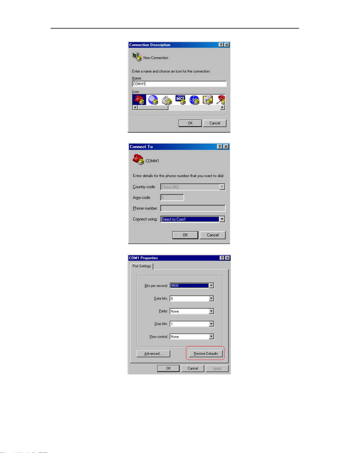
Run terminal emulator (such as Hyper Terminal on Windows 9X/2000/XP/Vista) on the
Computer. Set the terminal communication parameters as follows: Set the baud rate to 9600,
data bit to 8, parity check to none, stop bit to 1, flow control to none and select the terminal
type as auto-detection.
Logging in Ethernet Switch
17
Figure 1-2 Set up new connection
Figure 1-3 Configure the port for connection
Figure 1-4 Set communication parameters

Logging in Ethernet Switch
18
W o rk s ta ti on
W o rk s ta ti on
S e rv er
P C ( f or c o nf ig ur ing th e sw i tc h
v ia T e ln et )
E th e rn e t p o rt
E th e rn e t
W o rk s ta ti on
W o rk s ta ti on
S e rv er
P C ( f or c o nf ig ur ing th e sw i tc h
v ia T e ln et )
E th e rn e t p o rt
E th e rn e t
Step 3:
The Ethernet switch is powered on. Display self-test information of the Ethernet switch and
prompt you to press Enter to show the command line prompt such as < > after you have
entered the correct username and password. The initial username is admin and the matched
password is admin. It is suggested modifying the initial password after the first logging in.
Please remember the modified password. If the password is forgotten, please contact us as
soon as possible. Modify password refers to Change password.
Step 4:
Input a command to configure the Ethernet switch or Configuration Mode the operation
state. Input a “?” to get an immediate help. For details of specific commands, refer to the
following chapters.
1.2 Set up Configuration Environment through Telnet
1.2.1 Connect PC to Ethernet Switch through Telnet
After you have correctly configured IP address of a VLAN interface for an Ethernet Switch
via Console port (the way to configure switch via console refers to Set up Configuration
Environment via the Console Port; the way to configure ip address of switch refers to 03 using
ip address command in VLAN interface mode), and make sure PC can ping the switch, then
you can telnet this Ethernet switch and configure it.
Step 1:
Authenticate the Telnet user via the Console port before the user logs in by Telnet.
Step 2:
To set up the configuration environment, connect the Ethernet port
of the PC to that of the Ethernet switch via the LAN.
Figure 1-5 Set up configuration environment through telnet

Logging in Ethernet Switch
19
Step 3:
Run Telnet on the PC and input the IP address of the VLAN connected to the PC port.
Figure 1-6 Run Telnet
Step 4:
The terminal displays “Username (1-32 chars):” and prompts the user
to input the login username and password. After you input the correct username and
corresponded password, it displays the command line prompt (such as < >). If the prompt
“Too many users!” appears, it indicates that too many users are connected to the Ethernet
through the Telnet at this moment. In this case, please reconnect later. At most 5 Telnet users
are allowed to log in to the series Ethernet Switches simultaneously. Default username is
admin and the password is admin. If the default password has been modified, it requires the
modified password.
Step 5: Use the corresponding commands to configure the Ethernet switch or to monitor
the running state. Enter “?” to get the immediate help. For details of specific commands, refer
to the following chapters.
Note:
When configuring the Ethernet switch via Telnet, do not modify the IP address of it
unnecessary, for the modification might cut the Telnet connection.
1.2.2 Telnet Ethernet Switch through Ethernet Switch
Switch can be both the Telnet server and client. After a user has telnet to a switch from PC,
he or she can configure another switch through this switch via Telnet. The local switch serves
as Telnet client and the peer switch serves as Telnet server. If the ports connecting these two
switches are in a same local network, their IP addresses must be configured in the same
network segment. Otherwise, the two switches must establish a route that can reach each
other.
As shown in the figure below, after you telnet to an Ethernet switch (that is Telnet Client in

Logging in Ethernet Switch
20
Telnet Client
PC
Telnet Server
Figure 1-7), you can run telnet command to log in and configure another Ethernet switch
(that is Telnet Server in Figure 1-7).
Figure 1-7 Provide Telnet Client service
Step 1:
Configure IP address for the switch (that is Telnet Client in Figure 1-7). The way to
configure switch via console refers to Set up Configuration Environment via the Console Port;
the way to configure ip address of switch refers to 03 using ip address command in VLAN
interface mode).
Step 2:
The user logs in the Telnet Client (Ethernet switch). For the login process, refer to the
section describing “Connect PC to Ethernet Switch through Telnet”.
Step 3:
Perform the following operations on the Telnet Client:
#telnet A.B.C.D (A.B.C.D is the IP address of the Telnet Server.)
Step 4:
Enter the preset login password and you will see the prompt such < >. If the prompt “Too
many users!” appears, it indicates that too many users are connected to the Ethernet through
the Telnet at this moment. In this case, please connect later.
Step 5:
Use the corresponding commands to configure the Ethernet switch or Configuration Mode
it running state. Enter “?” to get the immediate help. For details of specific commands, refer to
the following chapters.

Command Line Interface
Chapter 2. Command Line Interface
This chapter describes command line interface (CLI) which you may use to configure your
switch. It contains flowing sections:
Introduction of CLI
CLI mode
Feature and functions of CLI
Symbols in command
Parameters in command
2.1 Introduction of Command Line Interface
Ethernet Switches provide a series of configuration commands and command line
interfaces for configuring and managing the Ethernet switch. The command line interface has
the following characteristics:
Local configuration via the Console port.
Local or remote configuration via Telnet.
Hierarchy command protection to avoid the unauthorized users accessing Ethernet switch.
Enter a “?” to get immediate online help.
Provide network testing commands, such as Tracert and Ping, to fast troubleshoot the
network.
Provide various detailed debugging information to help with network troubleshooting.
Log in and manage other Ethernet switch directly, using the Telnet command.
Provide FTP/TFTP/Xmodem service for the users to upload and download files.
The command line interpreter searches for target not fully matching the keywords. It is ok
for you to key in the whole keyword or part of it, as long as it is unique and not ambiguous.
2.2 Command Line Configuration Mode
Ethernet Switches provide hierarchy protection for the command lines to avoid
unauthorized user accessing illegally.
Commands are classified into three levels, namely visit and monitoring level, configuration
level and management level. They are introduced as follows:
Visit and monitoring level: Commands of this level involve command of network diagnosis

Command Line Interface
22
tool (such as ping and tracert), command of switch between different language environments
of user interface (language-mode) and telnet command etc and including the display
command and the debugging command, are used to system maintenance, service fault
diagnosis, etc. The operation of saving configuration file is not allowed on this level of
commands.
Configuration level: Service configuration commands, including routing command and
commands on each network layer are used to provide direct network service to the user.
Management level: They are commands that influence basis operation of the system and
system support module, which plays a support role on service. Commands of this level
involve file system commands, FTP commands, TFTP commands, Xmodem downloading
commands, user management commands, and level setting commands.
At the same time, login users are classified into three levels that correspond to the three
command levels respectively. After users of different levels logging in, they can only use
commands at the levels that are equal to or lower than their own level.
In order to prevent unauthorized users from illegal intrusion, user will be identified when
switching from a lower level to a higher level with username username [privilege level]
{password encryption-type password} command. For the sake of confidentiality, on the screen
the user cannot see the password that he entered. Only when correct password is input for
three times, can the user switch to the higher level. Otherwise, the original user level will
remain unchanged.
Different command configuration mode is implemented according to different requirements.
They are related to one another. For example, after logging in the Ethernet switch, you will
enter user mode, in which you can only use some basic functions such as displaying the
running state and statistics information. In user mode, key in enable to enter privileged mode,
in which you can key in different configuration commands and enter the corresponding
configuration modes.
The command line provides the following configuration modes:
User Mode
Privileged Mode
Global Configuration Mode
Interface Configuration Mode
VLAN Configuration Mode
AAA Configuration Mode
RADIUS Configuration Mode
Domain Configuration Mode
VLAN-interface Configuration Mode

Command Line Interface
23
Command
Configuration
Mode
Function
Prompt
Command to enter
Command to
exit
User Mode
Show the basic
information
about
operation and
statistics
Switch>
Enter right after
connecting the switch
exit disconnects
to the switch
Privileged mode
Show the basic
information
about
operation and
statistics and
manage the
system
Switch#
Key in enable in user
mode
exit returns to
user mode; quit
disconnects to
the switch
Global
Configuration
Mode
Configure
system
parameters
Switch
(config)#
Key in configure
terminal in privileged
Mode
exit and end
returns to
privileged mode;
quit disconnects
to the switch
Interface
Configuration
Mode
Configure
Interface
parameters
Switch
(config-if-et
hernet-0/0/
1)
Key in interface
ethernet 0/0/1 in global
Configuration Mode
exit returns to
global
configuration
mode and end
returns to
privileged mode;
quit disconnects
to the switch
VLAN
Configuration
Mode
Configure
VLAN
parameters
Switch
(config-if-Vl
an)#
Key in vlan 1 in system
Configuration Mode
AAA Configuration
Mode
Create domain
Switch
(config-aaa
)#
Key in aaa in global
configuration mode
RADIUS
Configuration
Mode
Configure
RADIUS server
parameters
Switch
(config-radi
us-default)#
Key in radius host
default in AAA
configuration mode
exit returns to
privileged mode
and end returns
to AAA
configuration
mode; quit
disconnects to
the switch
Domain
Configuration
Mode
Configure
domain
parameters
Switch
(config-aaa
-test.com)#
Key in domain
test.com in AAA
configuration mode
VLAN interface
Configure IP
Switch(conf
Key in interface
end returns to
SuperVLAN-interface Configuration Mode
RIP Configuration Mode
OSPF Configuration Mode
PIM Configuration Mode
The following table describes the function features of different Configuration Modes and
the ways to enter or quit.
Table 2-1 Function feature of Command Configuration Mode

Command Line Interface
24
Configuration
Mode
interface
parameters for
a VLAN or a
VLAN
aggregation
ig-if-vlanInt
erface-22)#
vlan-interface 22 in
global configuration
mode
privileged mode
exit returns to
global
configuration
mode and quit
disconnects to
the switch
SuperVLAN
interface
Configuration
Mode
Configure
Supervlan
interface
parameters
Switch(conf
ig-if-superV
LANInterfac
e-1)#
Key in interface
supervlan-interface 1
in global configuration
mode
PIM Configuration
Mode
Configure PIM
parameters
Switch(conf
ig-router-pi
m#
Key in pim in global
configuration mode
RIP Configuration
Mode
Configure RIP
parameters
OSPF
Configuration
Mode
Configure
OSPF
parameters
Switch(conf
ig-router-os
pf#
Key in route ospf in
global Configuration
Mode
Command
Purpose
Examples
help
Obtain a brief description of the
help system in any command
mode.
Switch>help
System mode commands:
cls clear screen
help description of the interactive help
ping ping command
……
Abbreviated-co
mmand-entry?
Obtain a list of commands that
begin with a particular
character string.
Switch(config)#interf?
interface
?
List all commands available for
a particular command mode.
Switch>?
System mode commands:
cls clear screen
help description of the interactive help
ping ping command
……
command?
List the associated keywords
for a command.
Switch(config)#spanning-tree ?
forward-time config switch delaytime
hello-time config switch hellotime
max-age config switch max agingtime
priority config switch priority
<enter> The command end.
2.3 Feature and Functions of Command Line
2.3.1 Help of Command Line
Table 2-2 You can get the help information through the help commands, which are described as follows.

Command Line Interface
25
command
keyword?
List the associated arguments
for a keyword.
Switch(config)#spanning-tree forward-time ?
INTEGER<4-30> switch delaytime:
<4-30>(second)
Key or Command
Function
Press <Ctrl+C> when the display pauses
Stop displaying and executing command.
Press other key when the display pauses
Continue to display the next screen of
information.
Press <Enter> when the display pauses
Continue to display the next line of information.
Operation
Key
Result
Retrieve the previous history
command
Up cursor key <↑> or
<Ctrl+P>
Retrieve the previous history
command, if there is any.
Retrieve the next history
command
Down cursor key <↓> or
<Ctrl+N>
Retrieve the next history command, if
there is any.
Note:
To switch to the Chinese display for the above information, perform the terminal
language {chinese | english} command in privileged mode.
2.3.2 Displaying Characteristics of Command Line
Command line interface provides the following display characteristics:
For users’ convenience, the instruction and help information can be displayed
in both English and Chinese.
For the information to be displayed exceeding one screen, pausing function is provided. In
this case, users can have three choices, as shown in the table below.
Table 2-3 Functions of displaying
2.4 Show History Command of Command Line
Command line interface provides the function similar to that of DosKey. The commands
entered by users can be automatically saved by the command Line interface and you can
invoke and execute them at any time later. History command buffer is defaulted as 100. That
is, the command line interface can store 100 history commands for each user. The operations
are shown in the table below.
Table 2-4 Retrieve history command

Command Line Interface
26
Error messages
Causes
Unrecognized command
Cannot find the command.
Cannot find the keyword.
Wrong parameter type.
The value of the parameter exceeds the range.
Incomplete command
The input command is incomplete.
Too many parameters
Enter too many parameters.
Ambiguous command
The parameters entered are not specific.
Note:
Cursor keys can be used to retrieve the history commands in Windows 9X/2000/XP
Terminal and Telnet.
2.5 Common Command Line Error Messages
All the input commands by users can be correctly executed, if they have passed the
grammar check. Otherwise, error messages will be reported to users. The common error
messages are listed in the following table.
Table 2-5 Common command line error messages
elements.
optional element.
2.6 Symbols in Command
This publication uses these conventions to convey instructions and information:
Command descriptions use these conventions:
Commands and keywords are in boldface text.
Arguments for which you supply values are in italic.
Square brackets ([ ]) mean optional elements.
Braces ({ }) group required choices, and vertical bars ( | ) separate the alternative
Braces and vertical bars within square brackets ([{ | }]) mean a requiredchoice within an
Interactive examples use these conventions:
Terminal sessions and system displays are in screen font.
Information you enter is in boldface screen font.

Command Line Interface
27
Nonprinting characters, such as passwords or tabs, are in angle brackets (< >).
2.7 Parameter in Command
There are 5 types of parameters:
Integer
The two numbers in the angle brackets (<>), connecting by hyphen (-) mean this
parameter is the integer between these two numbers.
For example: INTEGER<1-10> means user can key in any integer which can be more than
or equal to 1 and less than or equal to 10, such as 8.
IP address
A.B.C.D means an IP address.
For example: 192.168.0.100 is a valid IP address.
MAC address
H:H:H:H:H:H means a MAC address. If a multicast MAC address is needed, there would
be corresponded prompt.
For example: 01:02:03:04:05:06 is a valid MAC address.
Interface list
Interface list is prompt as STRING<3-4>. Port parameter interface-num consists of port
type and port number. Port type is Ethernet and port number is device/slot-num/port-num.
Device means stack value which is 0; slot-num means slot number (S6424-S2C2 supports
slot 0 and 1 and S6424-S2C2 supports slot 0, 1 and 2); port-num is the port number in the slot
(S6424-S2C2 is in the range of 1 to 24 and S6424-S2C2 is in the range of 1 to 48). Port
parameter interface-list means multiple ports. Seriate interfaces with the same type can be
linked by “to”, but the port number behind the “to” must be larger than the one in the front, and
this argument only can be repeated up to 3 times. The special declaration of interface
parameter interface list will be displayed in the command.
For example: Showing spanning-tree interface ethernet 0/0/1 ethernet 0/0/3 to ethernet
0/0/5 means showing the spanning-tree information about interface ethernet 0/0/1, ethernet
0/0/2, ethernet 0/0/3, ethernet 0/0/4 and ethernet 0/0/5.
String
The prompt STRING<1-19> means a character string which is in the length of1 to 19.
Enter “?” to see the parameter description of this command.

Manage Users
28
Chapter 3. Manage Users
There are three kinds of users:
Super-administrator
Administrator
Normal user
The normal users can only be in the user's mode after logging in the switch
so they can only check the basic information about operation and statistics; administrator
can enter each configuration mode to check and manage the system; super-administrator can
both manage the system and all kinds of users.
Note:
Normal users cannot configure the switch and change their own password.
Administrator can manage himself; for example, change his own privilege and
password. It cannot create or delete other users and change other user’s password
and privilege.
This chapter contains following sections:
System default user
Add users
Change password
Modify User's Privilege Level
Delete User
Show users
3.1 System Default User
There is an internal username with password called Super-administrator. It processes the
superior priority in the switch to manage both the users and the switch.
The username of Super-administrator is admin and its initial password is admin. It is
suggested modifying the password after the initial-logging in. This username and its
administrator privilege cannot be deleted and modified.
Note:
There must be only one super-administrator and all the configurations in the manual
is setting super-administrator as example.

Manage Users
29
Step
Command
Description
1
enable
Enter privileged mode
2
config terminal
Enter global configuration mode
3
username username privilege
privilege <0,1> password
password
Adding a new user and specified the privilege.
4
show username
Check the configuration.
5
exit
Exit to user mode
6
copy running-config startup-config
Save the configuration
3.2 User’s Authentication
User’s authentication can be divided into local authentication and remote authentication:
Local authentication: The users’ account and password are saved in local database. All
users are supported by local authentication.
Remote authentication: The users’ account and password are saved in
RADIUS/TACACS+ server. Super-administrator “admin” is not supported by remote
authentication.
3.3 Local Authentication Configuration
3.3.1 Add Users
At most 15 users can be added. Log in the switch first as Super-administrator and create
new users as following steps:
Table 3-1 Add users
Note:
Username: it means the name of the user to be added which must be 1 to 32
printable characters without '/',':','*','?','\\','<','>','|','"'.
Level: means the priority of the user to be added which is the number between 0 and
15. 0 and 1 mean the normal user and 2 to 15 mean the administrator.
encryption-type: it can be 0 or 7. 0 means clear text and 7 means encrypted text(not
supported now).
privilege it can be 0, 1 or 2 to 15. 0 and 1 mean normal users while 2 to 15 mean
administrators.
Password: the login password of new-added user which is 1 to 16 characters.
If the user's privilege level is not specified, it will default to be normal user. There is up
to 8 users in the system.
Caution: Case-sensitive is for password but not username.
Example:
!Create administrator "FoxGate" with its password being admin and privilege level is 3
Switch(config)#username FoxGate privilege 3 password 0 admin

Manage Users
30
Step
Command
Description
1
username change-password
Enter the modified password following the
prompt. The new password will be effective in
the next log in.
2
exit
Exit to user mode
3
copy running-config startup-config
Save the configuration
Ste
p
Command
Description
1
username username privilege privilege<0-15>
Modify user’s privilege.
2
show username
Check configuration.
3
exit
Exit to user mode
4
copy running-config startup-config
Save the configuration
3.3.2 Change Password
In global configuration mode, Super-administrator "admin" can use following command to
change the password of all users, but other administrators can only change their own
password. Normal users cannot modify their own password.
Enter global configuration mode (how to enter global configuration mode refers to the first
2 steps in Table 3-1) before following the below steps:
Table 3-2 Modify password
Example:
!Change the password of user "admin" to be 123456
Switch(config)#username change-password
please input you login password : ******
please input username :admin
Please input user new password :******
Please input user confirm password :******
change user password success.
3.3.3 Modify User's Privilege Level
In global configuration mode, only Super-administrator "admin" can modify the privilege
level of other users. Enter global configuration mode (how to enter global configuration mode
refers to the first 2 steps in Table 3-1) before following the below steps:
Table 3-3 Modify User's Privilege Level
Note:
Username: means the name of the existed user to be modified which must be 1 to 32
printable characters without '/',':','*','?','\\','<','>','|','"'. If the entered username is not
existed, add it to be the new one.

Manage Users
31
Ste
p
Command
Description
1
no username username
Delete user.
2
show username
Check configuration.
3
exit
Exit to user mode
4
copy running-config startup-config
Save the configuration
Step
Command
Description
1
show username
Show specific user.
2
show users
Show users’ log. At most 5 users are permitted on line at
the same time.
Level: means the priority of the existed user (except the Super-administrator) to be
modified which is the number between 0 and 15. 0 and 1 mean the normal user and 2
to 15 mean the administrator.
Caution: Case-sensitive is for password but not username.
Example:
!Modify the privilege of the existed user "admin" to be 1 and its password to be 1234
Switch(config)#username FoxGate privilege 0 password 0 1234
3.3.4 Delete User
Only Super-administrator "admin" can add and delete user in global configuration mode.
Enter global configuration mode (how to enter global configuration mode refers to the first 2
steps in Table 3-1) before following the below steps:
Table 3-4 Delete user
Note:
Username: means the name of the user to be deleted.
When deleting a user which is used, it will be disconnected before delete it.
Example:
!Delete user "admin"
Switch(config)#no username admin
3.3.5 Show Users
After configuration, you can use following steps to check it. Any configuration mode is
permitted.
Table 3-5 Show users

Manage Users
32
Operation
Command
Description
Enter global configuration
configure terminal
-
Enable RADIUS remote
authentication
muser radius name
{chap|pap} [local]
Selected
If “local“ is configured, it
means local authentication is
used if remote authentication
failed.
By default, it is local
authentication
Enter AAA configuration mode
aaa
-
Create RADIUS server name and
enter RADIUS configuration
mode
radius host name
-
Configure IP of
authentication/accounting
RADIUS server
{primary-acct-ip |
primary-auth-ip } A.B.C.D
{ accounting port |
authentication port }
Selected
Authentication and accounting
port should be the same as
that of RADIUS server.
Generally, they are:
Accounting port:1813
Authentication port:1812
Configure shared-key of
authentication/accounting
RADIUS server
{acct-secret-key|
auth-secret-key} key
Selected
Shared-key should be the
same as that of RADIUS
server.
Show configuration
show muser
-
3.4 Remote Authentication Configuration
3.4.1 Configure RADIUS to Be Remote Authentication Server
Table 3-6 Configure RADIUS remote authentication
3.4.2 Configure TACACS+ remote authentication
Configuring user’s login through TACACS+ server authentication, accounting and
authorization through TACACS+ server can be chosen. When configuring TACACS+
authorization, configure corresponded priority to users first. There are 16 levels (0-16)
priorities but there are only 2 levels (0-1 means normal users and 2-15 means administrators)
for switches. When configuring TACACS+ un-authorization, the priority is determined by
priv_lvl replied from remote server (no reply means administrator). Authorization failure
means normal user.
When configuring TACACS+ accounting, it begins with the pass of authentication and ends
with user’s exit.

Manage Users
33
Operation
Command
Description
Enable TACACS+
authorization/accounting
muser tacacs+ {account [local] |author
[local]|local}
Selected If local is
configured, it
means local
authentication is
used if remote
authentication
failed.
By default, it is
local
authentication
Configure
IP/shared-key/TCP
port/timeout of TACACS+
remote server
tacacs+ { priamary | secondary } server
ipaddress [key keyvalue] [port portnum]
[timeout timevalue]
Selected
By default, TCP
port is 49 and
timeout is5
seconds.
Show TACACS+
configuration
show tacacs+
Show current authentication
show muser
-
Table 3-7 Configure TACACS+ remote authentication

Ethernet Port Configuration
34
Port
type
Ingress
Egress
Untagged
packet
Tagged packet
Access
port
Receive it and
add a tag with
VID being
equal to PVID.
If VID of the
packet is equal
to the port
permitted VID,
receive it; if VID
is different,
discard it.
Strip the Tag and transmit the packet as the VID
of the packet is equal to the port permitted VID
Hybrid
port
If VID of the packet is equal to the port permitted
untag VID, remove the tag and transmit it; If VID
of the packet is equal to the port permitted tag
VID, keep the tag and transmit it.
Trunk
port
If VID of the packet is equal to the port permitted
VID, keep the tag and transmit it.
Chapter 4. Ethernet Port
Configuration
This chapter describes the types of interfaces on switches and how to configure them.
4.1 Ethernet Port Overview
4.1.1 Link Type of Ethernet Ports
An Ethernet port can operate in one of the three link types:
Access: An access port only belongs to one VLAN, normally used to connect user device.
Trunk: A trunk port can belong to more than one VLAN. It can receive/send packets from/to
multiple VLANs and is generally used to connect another switch. The packet sent from this
port can only be with tag label.
Hybrid: A hybrid port can belong to multiple VLANs, can receive, or send packets for
multiple VLANs, used to connect either user or network devices. It allows packets of multiple
VLANs to be sent with or without the tag label
4.1.2 Configuring Default VLAN ID for Ethernet Port
Both hybrid port and trunk port can belong to more than one VLAN, but there is a default
VLAN for each port. The default VLAN ID (PVID) is VLAN 1 and it can be changed if
necessary (the way to change PVID refers to Table 4-5)
4.1.3 Handling packets
Different ports have different ways to handle the packet. Details are in Table 4-1.
Table 4-1 Different port handles different packet

Ethernet Port Configuration
35
Step
Command
Description
1
configure terminal
Enter global configuration mode.
2
interface ethernet
{ device-num/slot-num/port-num }
Enter interface configuration mode.
4.2 Configure Ethernet Port
Ethernet port configuration includes:
Basic Ethernet Port Configuration
Combo port
Enable/disable ingress filtering
Acceptable-frame type for Ethernet port
Enable/Disable Flow Control for Ethernet Port
Display and Debug Ethernet Port
4.2.1 Basic Ethernet Port Configuration
Basic Ethernet port configuration includes:
Enter interface configuration mode
Enter interface range mode
Basic port configuration
Configure default VLAN
Add a port to a VLAN
Basic port configuration
4.2.1.1 Enter Interface Configuration Mode
Before configuring the Ethernet port, enter interface configuration mode first.
Perform the following configuration in privileged mode.
Table 4-2 Enter interface configuration mode
Note:
The details of the parameters in Table 4-7 are in Basic Port Configuration.
4.2.1.2 Enter Interface Range Mode
Sometimes we need to configure a patch of ports with the same configurations. We can
use interface range mode to avoid the repetition. Perform the following configuration in
privileged mode.

Ethernet Port Configuration
36
Step
Command
Description
1
configure terminal
Enter global configuration mode.
2
interface range interface-list
Enter interface range configuration
mode.
Operation
Command
Remarks
Enter global configuration mode
configure terminal
Enter interface configuration mode
interface ethernet
device-num/slot-num/port-num
Configure port mode to be
Access、Hybrid or Trunk
switchport mode {access|hybrid|trunk}
Show port mode
show interface ethernet
device-num/slot-num/port-num
Table 4-3 Enter interface range mode
Example:
! Divide interfaces from Ethernet 0/0/1 to Ethernet 0/0/16 into an interface range.
Switch(config)#interface range ethernet 0/0/1 to ethernet 0/0/16
Switch(config-if-range)#
4.2.1.3 Configure Port Mode
Table 4-4 Configure port mode
Example:
! There is VLAN 1-20. Configure uplink port e 0/1/1 to be trunk, and it can transceive
packets of VLAN1-20
Switch(config)#vlan 1-20
Switch(config-if-vlan)#switchport ethernet 0/1/1
Add VLAN port successfully.
Switch(config-if-vlan)#interface ethernet 0/1/1
Switch(config-if-ethernet-0/1/1)#switchport mode trunk
Switch(config-if-ethernet-0/1/1)# show interface brief ethernet 0/1/1
Port Desc Link shutdn Speed Pri PVID Mode TagVlan UtVlan
e0/1/1 down FALSE auto 0 1 trk 1-20
Total entries: 1.

Ethernet Port Configuration
37
Operation
Command
Remarks
Enter global configuration mode
configure terminal
Enter interface configuration mode
interface ethernet
device-num/slot-num/port-num
Modify port default VLAN
switchport default vlan vlan_id
4.2.1.4 Configure Default VLAN
Table 4-5 Configure default VLAN
Example:
! The first four ports (e 0/0/1 – e0/0/4)connect to different server. These four servers
should be isolated. And the servers belong to VLAN 10,VLAN 20,VLAN 30 and VLAN 40
Switch(config)#vlan 10
Switch(config-if-vlan)#switchport ethernet 0/0/1
Add VLAN port successfully.
Switch(config-if-vlan)#vlan 20
Switch(config-if-vlan)#switchport ethernet 0/0/2
Add VLAN port successfully.
Switch(config-if-vlan)#vlan 30
Switch(config-if-vlan)#switchport ethernet 0/0/3
Add VLAN port successfully.
Switch(config-if-vlan)#vlan 40
Switch(config-if-vlan)#switchport ethernet 0/0/4
Add VLAN port successfully.
Switch(config-if-vlan)#interface ethernet 0/0/1
Switch(config-if-ethernet-0/0/1)#switchport default vlan 10
Switch(config-if-ethernet-0/0/1)#interface ethernet 0/0/2
Switch(config-if-ethernet-0/0/2)#switchport default vlan 20
Switch(config-if-ethernet-0/0/2)#interface ethernet 0/0/3
Switch(config-if-ethernet-0/0/3)#switchport default vlan 30
Switch(config-if-ethernet-0/0/3)#interface ethernet 0/0/4
Switch(config-if-ethernet-0/0/4)#switchport default vlan 40
Switch(config-if-ethernet-0/0/4)#vlan 1
Switch(config-if-vlan)#no switchport ethernet 0/0/1 to ethernet 0/0/4
Switch(config-if-vlan)#show interface brief e 0/0/1 to e 0/0/4
Port Desc Link shutdn Speed Pri PVID Mode TagVlan UtVlan
e0/0/1 down false auto 0 10 hyb 10

Ethernet Port Configuration
38
Operation
Command
Remarks
Enter global configuration mode
configure terminal
Enter interface configuration mode
interface ethernet
device-num/slot-num/port-num
Add Hybrid port to specific VLAN and
keep the packet VID
switchport hybrid tagged vlan vlan-list
Add Hybrid port to specific VLAN and
strip the packet VID
switchport hybrid untagged vlan vlan-list
Delete Hybrid port from specific VLAN
no switchport hybrid vlan vlan-list
Add Trunk port to specific VLAN
switchport trunk allowed vlan vlan-list
Delete Trunk port from specific VLAN
no switchport trunk allowed vlan vlan-list
e0/0/2 down false auto 0 20 hyb 20
e0/0/3 down false auto 0 30 hyb 30
e0/0/4 down false auto 0 40 hyb 40
Total entries: 4 .
4.2.1.5 Add Port to VLAN
User can add current Ethernet port to a specific VLAN, thus, the Ethernet port can forward
packet of the vlan.
Hybrid port and Trunk port can belong to multiple VLANs and Access port can only belong
to one VLAN, which is the default vlan. By default, all ports belong to VLAN 1.
In VLAN configuration mode, user can use switch port Ethernet command to add a port to
vlan, please refer to “VLAN configuration” chapter.
There is another way to add port to a vlan, in interface configuration mode.
Table 4-6 Add a port to a VLAN
There are two ways to add an Access port to VLAN: one is to configure port default VLAN;
the other is to add the port to another VLAN directly. Access port can only belong to one
VLAN, so this port will be auto-deleted from the original VLAN.
Example:
e 0/0/1 is Hybrid. Configure this port keeping tag of VLAN 10。
Switch(config)#vlan 10
Switch (config-if-vlan)#interface ethernet 0/0/1
Switch (config-if-ethernet-0/0/1)#switchport hybrid tagged vlan 10
Switch (config-if-ethernet--0/0/1)#show interface brief e 0/0/1
Port Desc Link shutdn Speed Pri PVID Mode TagVlan UtVlan
e0/0/1 down false auto 0 1 hyb 10 1
Total entries: 1.

Ethernet Port Configuration
39
Operation
Command
Description
Disable specific port
shutdown
By default, the port is enabled. If you want
to re-enable the port, use no shutdown
command.
Configure duplex of a
port
duplex { auto | full |
half }
no duplex
10/100/1000BASE-T supports full duplex,
half duplex and auto-negotiation;
1000BASE-X supports full duplex and
auto-negotiation. By default, the working
mode is auto. If duplex is auto, the speed
will be auto.
Configure speed of a
port
speed { speed-value |
auto }
no speed
10/100/1000BASE-T supports 10Mbps,
100Mbps and 1000Mbps; 1000BASE-X
supports only 1000Mbps. By default, the
speed is auto. If the speed is auto, the
duplex will be auto.
Configure priority of a
port
priority priority-value
no priority
Priority-value could be 0 to 7 and the
default interface priority is 0. The larger the
priority value is, the higher the priority is.
And the packet with the higher priority will
be quickly handled.
Configure port
description
description
description-list
The description is used to distinguish ports.
By default, the description of a port is
empty.
4.2.1.6 Basic Port Configuration
Following basic port configurations are in the interface configuration mode.
Table 4-7 Basic port configuration
4.3 Combo Port
A combo port is formed by two Ethernet ports on the panel, one of which is an optical port
and the other is an electrical port. For the two ports forming a combo port, only one works at a
given time. They are TX-SFP multiplexed. You can specify a combo port to operate as an
electrical port or an optical port as needed. That is, a combo port cannot operate as both an
electrical port and an optical port simultaneously.
Generally, if both electrical port and optical port are all inserted, only electrical port can
work. If user wants to use optical port, please unplug the electrical port.
4.4 Enable/Disable Ingress Filtering
If ingress filtering is enabled, the received 802.1Q packets which do not belong to the
VLAN where the interface locates will be dropped. The packet will not be dropped if the

Ethernet Port Configuration
40
Operation
Command
Enable ingress filtering
ingress filtering
Disable ingress filtering
no ingress filtering
Operation
Command
Enable ingress acceptable-frame
ingress acceptable-frame { all | tagged }
Disable ingress acceptable-frame
no ingress acceptable-frame
function is disabled and the VLAN which the packet belonged to is existed.
Perform the following configuration in global configuration mode.
Table 4-8 Enable/disable ingress filtering
Note:
By default, ingress filtering is enabled.
Example:
! Disable VLAN ingress filtering
Switch(config)#no ingress filtering
Disable ingress filtering successfully!
! Enable VLAN ingress filtering
Switch(config)#ingress filtering
Enable ingress filtering successfully!
4.5 Acceptable-Frame Type for Ethernet Port
We can configure ingress acceptable frame mode to be all types or only tagged. The
untagged frame will not be accepted after the port setting to be only tagged.
Perform the following configuration in interface configuration mode.
Table 4-9 Configure ingress acceptable-frame
Note:
By default, ingress acceptable-frame is all.
Example:
! Configure Ethernet 0/0/5 only to receive tagged frame
Switch(config)#interface ethernet 0/0/5
Switch(config-if-ethernet-0/0/5)#ingress acceptable-frame tagged
Config acceptable-frame type successfully!
! Restore the default ingress acceptable-frame of Ethernet 0/0/5
Switch(config)#interface ethernet 0/0/5

Ethernet Port Configuration
41
Option
Command
Enable Ethernet port flow control
flow-control
Disable Ethernet port flow control
no flow-control
Switch(config-if-ethernet-0/0/5)#no ingress acceptable-frame
Config acceptable-frame type successfully!
4.6 Enable/Disable Flow Control for Ethernet Port
After enabling flow control in both the local and the peer switch, if congestion occurs in the
local switch, the switch will inform its peer to pause packet sending. Once the peer switch
receives this message, it will pause packet sending, and vice versa. In this way, packet loss is
reduced effectively. The flow control function of the Ethernet port can be enabled or disabled
through the following command.
Perform the following configuration in interface configuration mode.
Table 4-10 Enable/Disable Flow Control for Ethernet Port
Note:
By default, Ethernet port flow control is disabled.
Example:
! Enable flow-control on ethernet 0/0/5
Switch(config)#interface ethernet 0/0/5
Switch(config-if-ethernet-0/0/5)#flow-control
Setting successfully! flow-control is enable
! Disable flow-control on ethernet 0/0/5
Switch(config)#interface ethernet 0/0/5
Switch(config-if-ethernet-0/0/5)#no flow-control
Setting successfully! flow-control is disable
4.7 Display and Debug Ethernet Port
After the above configuration, execute show command in any configuration mode to
display the running of the Ethernet port configuration, and to verify the effect of the
configuration.
Execute clear interface command in user mode to clear the statistics information of the
port.

Ethernet Port Configuration
42
Operation
Command
Description
Clear the statistics
information of the
port.
clear interface [ interface-num |
slot-num ]
The information of the
interface includes:
numbers of unicast,
multicast and broadcast
message etc.
Display interface
description.
show description interface
[ interface-list ]
Display port
configuration
show interface [ interface-num ]
Display the statistic
information of
specified port or all
ports.
show statistics interface
[ interface-num ]
Display the statistic
information of all
interfaces
show statistic dynamic interface
Statistic information
refreshes automatically
every 3 seconds. Press
“Enter” to exit.
Display the utilization
information of all
ports
show utilization interface
The utilization information
of all ports includes
receiving and sending
speed, bandwidth
utilization rate, etc. Press
“Enter” to exit.
Table 4-11 Display and debug Ethernet port
Note:
Using clear interface command in global mode, if the interface-num and slot-num
are not assigned, the information of all interfaces is cleared. If the slot-num is
assigned, the port information of the assigned slot is cleared. In interface mode, only
the information of the current port can be cleared.
If port type and port number are not specified, the above command displays
information about all ports. If both port type and port number are specified, the
command displays information about the specified port.
Example:
! Show description of all port
Switch(config-if-ethernet-0/0/1)#show description interface
Port description
e0/0/1 test
e0/0/2
e0/0/3 FoxGate
e0/0/4
e0/0/5
……

Ethernet Port Configuration
43
! Show interface Ethernet 0/0/5
Switch(config-if-ethernet-0/0/1)#show interface ethernet 0/0/5
Ethernet e0/0/5 is enabled, port link is down
Hardware is Fast Ethernet, Hardware address is 00:0a:5a:11:b5:71
SetSpeed is auto, ActualSpeed is unknown, porttype is 10/100/1000M
Priority is 0
Flow control is disabled
PVID is 1
Port mode:hybrid
Tagged VLAN ID :
Untagged VLAN ID : 1
0 packets output
0 bytes, 0 unicasts, 0 multicasts, 0 broadcasts
0 packets input
0 bytes, 0 unicasts, 0 multicasts, 0 broadcasts
! Show statistic interface ethernet 0/0/2
Switch(config-if-ethernet-0/0/1)#show statistics interface ethernet 0/0/2
Port number : e0/0/2
input rate 0 bits/sec, 0 packets/sec
output rate 0 bits/sec, 0 packets/sec
64 byte packets:0
65-127 byte packets:0
128-255 byte packets:0
256-511 byte packets:0
512-1023 byte packets:0
1024-1518 byte packets:0
0 packets input, 0 bytes , 0 discarded packets
0 unicasts, 0 multicasts, 0 broadcasts
0 input errors, 0 FCS error, 0 symbol error, 0 false carrier
0 runts, 0 giants
0 packets output, 0 bytes, 0 discarded packets
0 unicasts, 0 multicasts, 0 broadcasts
0 output errors, 0 deferred, 0 collisions
0 late collisions
Total entries: 1.
! Show statistic dynamic interface

Ethernet Port Configuration
44
Switch(config-if-ethernet-0/0/1)#show statistics dynamic interface
Port Statistics Sat Jan 1 00:39:37 2000
port link Tx Pkt Tx Byte Rx Pkt Rx Byte Rx Rx
Status Count Count Count Count Bcast Mcast
===================================================================
e0/0/1 down 0 0 0 0 0 0
e0/0/2 down 0 0 0 0 0 0
e0/0/3 down 0 0 0 0 0 0
e0/0/4 down 0 0 0 0 0 0
e0/0/5 down 0 0 0 0 0 0
e0/0/6 down 0 0 0 0 0 0
e0/0/7 down 0 0 0 0 0 0
e0/0/8 down 0 0 0 0 0 0
e0/0/9 down 0 0 0 0 0 0
e0/0/10 down 0 0 0 0 0 0
e0/0/11 down 0 0 0 0 0 0
e0/0/12 down 0 0 0 0 0 0
e0/0/13 down 0 0 0 0 0 0
e0/0/14 down 0 0 0 0 0 0
e0/0/15 down 0 0 0 0 0 0
e0/0/16 down 0 0 0 0 0 0
e0/0/17 down 0 0 0 0 0 0
==========0->Clear Counters U->page up D->page down CR->exit============
! Show utilization interface
Switch(config-if-ethernet-0/0/1)#show utilization interface
Link Utilization Averages Sat Jan 1 00:43:44 2000
port link Receive Peak Rx Transmit Peak Tx
Status pkts/sec pkts/sec pkts/sec pkts/sec
==================================================================
e0/0/1 down 0 0 0 0
e0/0/2 down 0 0 0 0
e0/0/3 down 0 0 0 0
e0/0/4 down 0 0 0 0
e0/0/5 down 0 0 0 0
e0/0/6 down 0 0 0 0
e0/0/7 down 0 0 0 0

Ethernet Port Configuration
45
e0/0/8 down 0 0 0 0
e0/0/9 down 0 0 0 0
e0/0/10 down 0 0 0 0
e0/0/11 down 0 0 0 0
e0/0/12 down 0 0 0 0
e0/0/13 down 0 0 0 0
e0/0/14 down 0 0 0 0
e0/0/15 down 0 0 0 0
e0/0/16 down 0 0 0 0
e0/0/17 down 0 0 0 0
====spacebar->toggle screen U->page up D->page down CR->exit====
! Clear interface
Switch(config-if-ethernet-0/0/1)#clear interface
clear current port statistics information record successfully!

Ethernet Port Mirroring Configuration
46
Chapter 5. Ethernet Port Mirroring
Configuration
5.1 Configure Ethernet Port Mirroring
5.1.1 Overview
Mirroring refers to the process of copying packets that meet the specified rules to a
destination port. Generally, a destination port is connected to a data detect device, which
users can use to analyze the mirrored packets for monitoring and troubleshooting the
network.
Figure 5-1 Mirroring
5.1.1.1 Traffic Mirroring
Traffic mirroring maps traffic flows that match specific ACLs to the specified destination
port for packet analysis and monitoring. Before configuring traffic mirroring, you need to
define ACLs required for flow identification.
5.1.1.2 Port Mirroring
Port mirroring refers to the process of copying the packets received or sent by the
specified port to the destination port.
5.1.2 Mirroring
Switch support one-to-one and multiple-to-one mirroring.
Mirrored: mirror source can be port or packet sent or received by CPU
Mirror: For S6424-S2C2 switch, mirror port can be only one. If multiple mirror port is
configured, the last will be effective.

Ethernet Port Mirroring Configuration
47
Function
Specifications
Related command
Link
Mirroring
Traffic mirroring
mirrored-to
no mirrored-to
QoS configuration
Port mirroring
mirror destination-interface
mirror source-interface
Configuring Port Mirroring
Operation
Command
Description
Configure traffic
mirroring
mirrored-to { ip-group { acl-number |
acl-name } [ subitem subitem ] |
link-group { acl-number | acl-name }
[ subitem subitem ] } interface
ethernet interface-num
The command is for traffic
mirroring on the packets
which meet ACL rules (only
be effective on ACL permit
rules). The destination port
should be specified when
using this command for the
first time.
Cancel traffic
mirroring
no mirrored-to { ip-group { acl-number
| acl-name } [ subitem subitem ] |
link-group { acl-number | acl-name }
[ subitem subitem ] }
Note:
mirror port cannot be used as a normal port.
5.1.3 Configuring port mirroring
Table 5-1 Mirroring functions and related command
5.1.4 Mirroring Configuration
For mirroring features, see section Overview.
5.1.4.1 Configuring Traffic Mirroring
Configuration prerequisites
ACLs for identifying traffics have been defined. For defining ACLs, see the description on
the ACL module in QoS.
The destination port has been defined.
The port on which to perform traffic mirroring configuration and the direction of traffic
mirroring has been determined.
Configuration procedure
Perform the configuration in global configuration mode.
Table 5-2 Configure traffic mirroring
Note:
ip-group { acl-number | acl-name } [ subitem subitem ]: Specifies a basic or an
advanced ACL. The acl-number argument ranges from 2000 to 3999;acl-name:
Name of a string, start with letters without space and quotation mark;subitem: option
parameter for specifying the sub-item in acl-list, in the range of 0 to 127.

Ethernet Port Mirroring Configuration
48
Operation
Command
Description
Configure destination port (so
called monitor port)
mirror destination-interface
interface-num
This command will cancel
original port mirroring.
Configure source port (so
called mirrored port)
mirror source-interface
{ interface-list | cpu } { both |
egress | ingress }
both means both ingress and
egress; cpu means mirroring
cpu packets.
Show port mirroring
show mirror
link-group { acl-number | acl-name } [ subitem subitem ]: Specifies a Layer 2 ACL.
The acl-number argument ranges from 4000 to 4999; acl-name: Name of a string,
start with letters without space and quotation mark;subitem: option parameter for
specifying the subitem in acl-list, in the range of 0 to 127.
interface ethernet { interface-num }: Specifies destination port (also called monitor
port) of traffic.
Configuration example
! Mirror acl-list 2000 to Ethernet 0/0/1.
Switch(config)#access-list 2000 permit 1.1.1.1 0
Config ACL subitem successfully.
Switch(config)#mirrored-to ip-group 2000 interface ethernet 0/0/1
Config mirrored-to successfully.
5.1.4.2 Configuring Port Mirroring
Configuration prerequisites
The source port is specified and whether the packets to be mirrored are ingress or egress
is specified: ingress: only mirrors the packets received via the port; egress: only mirrors the
packets sent by the port; both: mirrors the packets received and sent by the port at the same
time.
The destination port is specified.
Configuration procedure
Perform the following configuration in global configuration mode.
Table 5-3 Configure port mirroring
Note:
A port cannot be monitor and mirrored port at the same time.
Configuration example
! Mirror egress of ethernet 0/0/1 to ethernet 0/0/12 to ethernet 0/1/1
Switch(config)#mirror destination-interface ethernet 0/1/1
Config monitor port successfully !
Switch(config)#mirror source-interface ethernet 0/0/1 to ethernet 0/0/12 egress
Config mirrored port successfully !

Ethernet Port Mirroring Configuration
49
! Mirror cpu both to ethernet 0/1/2
Switch(config)#mirror destination-interface ethernet 0/1/2
Config monitor port successfully !
Switch(config)#mirror source-interface cpu both
Config mirrored port successfully !

Configuring Port Utilization Alarm
50
Operation
Command
Remark
Enter global configuration mode
configure terminal
-
Enable(disable)port utilization
alarm with system mode
(no)alarm all-packets
required
Enter port configuration
interface ethernet interface-num
-
Enable(disable)port utilization
alarm with port mode
(no)alarm all-packets
Required
Configure alarm value
alarm all-packets threshold {exceed thresold |
normal thresold }
Optional
Chapter 6. Configuring Port
Utilization Alarm
6.1 Brief Introduction to Device Utilization Alarm
The device utilization alarm is used to monitor port bandwidth、CPU occupation and alarm
when congestion in order to administrator aware the running status between the network and
device.
Exceed: when port bandwidth utilization over “exceed”, it triggers congestion alarm.
Normal: when port bandwidth utilization less “exceed”, it triggers recover alarm CPU
utilization alarm also can set two trigger values, details as below:
Busy: when CPU utilization over “busy”, it triggers alarm of CPU busyness
Un-busy: when CPU utilization less “busy”, it triggers alarm of CPU idle Notes, all alarms
will show in the list of Syslog.
6.2 Configuring Device Utilization Alarm
6.2.1 Configuring Port Utilization Alarm
Using below commands to configure port utilization. Enable port utilization in system and
port mode by default. The “exceed” value equals 850M, the “normal” value equals 600M.
Table 6-1 Configuring port utilization alarm
6.2.2 Configuring CPU Utilization Alarm
Using below commands to configure CPU utilization. Enable CPU utilization by default.
The “busy” value equals 90%, the “unbusy” value equals 60%

Configuring Port Utilization Alarm
51
Operation
Command
Remark
Enter global configuration
mode
configure terminal
-
Enable(disable) CPU
utilization alarm
alarm cpu
Required
Configure congestion
value
alarm cpu threshold {busy thresold |unbusy thresold }
optional
Operation
Command
Remark
Display the enable status and
alarm value of CPU utilization
alarm
show alarm cpu
Perform either of the
commands
Display port utilization in system
mode
show alarm all-packets
Perform either of the
commands
Display port utilization and value in
port mode
show alarm all-packets interface
[ethernet interface-num]
Perform either of the
commands
Table 6-2 Configuring CPU utilization alarm
6.2.3 Displaying and Debugging Device Utilization Alarm
After finishing above configuration, you can show configuration by below commands.
Table 6-3 Displaying and debugging device utilization alarm
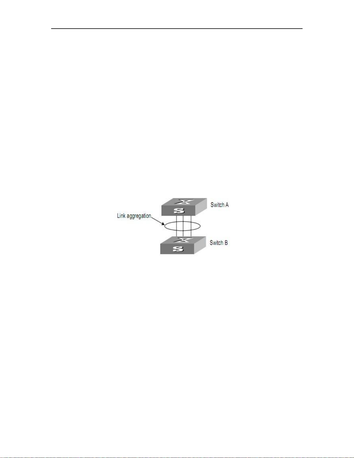
Link Aggregation Configuration
52
Chapter 7. Link Aggregation
Configuration
7.1 Overview
7.1.1 Introduction to Link Aggregation
Link aggregation means aggregating several ports together to form an aggregation group,
so as to implement outgoing/incoming load sharing among the member ports in the group and
to enhance the connection reliability.
Depending on different aggregation modes, aggregation groups fall into two types: static
LACP and dynamic LACP. Depending on whether or not load sharing is implemented,
aggregation groups can be load-sharing or non-load-sharing aggregation groups.
Figure 7-1 Network diagram for link aggregation configuration
For the member ports in an aggregation group, their basic configuration must be the same.
The basic configuration includes STP, QoS, VLAN, port attributes, and other associated
settings.
STP configuration, including STP status (enabled or disabled), link attribute (point-to-point
or not), STP priority, maximum transmission speed, loop prevention status.
QoS configuration, including traffic limiting, priority marking, default 802.1p priority, traffic
monitor, traffic redirection, traffic statistics, and so on.
VLAN configuration, including permitted VLANs, and default VLAN ID, tag vlan list for
hybrid port and allowed vlan list for trunk port.
Port attribute configuration, including port rate, duplex mode, and link type (Trunk, Hybrid
or Access). The ports for a static aggregation group must have the same rate and link type,
and the ports for a dynamic aggregation group must have the same rate, duplex mode (full
duplex) and link type.

Link Aggregation Configuration
53
7.1.2 Introduction to LACP
The purpose of link aggregation control protocol (LACP) is to implement dynamic link
aggregation and disaggregation. This protocol is based on IEEE802.3ad and uses LACPDUs
(link aggregation control protocol data units) to interact with its peer.
After LACP is enabled on a port, LACP notifies the following information of the port to its
peer by sending LACPDUs: priority and MAC address of this system, priority, number and
operation key (it is so called O-Key) of the port. Upon receiving the information, the peer
compares the information with the information of other ports on the peer device to determine
the ports that can be aggregated with the receiving port. In this way, the two parties can reach
an agreement in adding/removing the port to/from a dynamic aggregation group.
7.1.3 Operation Key (O-Key)
An operation key of an aggregation port is a configuration combination generated by
system depending on the configurations of the port (rate, duplex mode, other basic
configuration, and administrative key) when the port is aggregated.
1) The ports in the same aggregation group must have the same operation key (O-Key)
and administrative key (A-Key).
2) The administrative key (A-Key) and operation key (O-Key) of an LACP-enable
aggregation port is equal to its aggregation group ID+1.
3) The administrative key (A-Key) and operation key (O-Key) of an LACP-enable
aggregation port cannot be modified.
4) The operation key (O-Key) which is contained in LACPDU of an LACP-enable
aggregation port is the same as its peer.
7.1.4 Static Aggregation Group
7.1.4.1 Introduction to static aggregation
A static aggregation group is manually created. All its member ports are manually added
and can be manually removed. Each static aggregation group must contain at least one port.
When a static aggregation group contains only one port, you cannot remove the whole
aggregation group unless you remove the port.
LACP is disabled on the member ports of static aggregation groups, and enabling LACP
on such a port will not take effect.

Link Aggregation Configuration
54
7.1.4.2 Port status of static aggregation group
A port in a static aggregation group is only in one state: on, which means the port in a static
aggregation group must transceive packets. There can be at most 8 ports in a static
aggregation group.
7.1.5 Dynamic LACP Aggregation Group
7.1.5.1 Introduction to Dynamic LACP Aggregation Group
A dynamic LACP aggregation group is also manually created. All its member ports are
manually added and can be manually removed. Each dynamic aggregation group must
contain at least one port. When a dynamic aggregation group contains only one port, you
cannot remove the whole aggregation group unless you remove the port.
LACP is enabled on the member ports of dynamic aggregation groups, and disabling
LACP on such a port will not take effect.
7.1.5.2 Mode of Dynamic Aggregation Group
The mode of dynamic aggregation group can be active or passive. It is manually set by
users. The dynamic aggregation group in active mode will actively send LACPDUs; group in
passive mode will only response LACPDUs passively. When interconnecting with another
device, static mode can only interconnect with static mode; active mode can interconnect with
both active and passive mode, but passive mode can only interconnect with active mode. The
default mode is ACTIVE.
7.1.5.3 Port status of Dynamic Aggregation Group
A port in a dynamic aggregation group can be in one of the three states: bundle (bndl),
standby, and no-bundle (no-bndl). In dynamic aggregation group, only bundled ports can
transceive LACP protocol packets; others cannot.
Note:
In an aggregation group, the bundled port with the minimum port number serves as
the master port of the group, and other bundled ports serve as member ports of the
group.
No-bundled ports are the ports which fail to form link aggregation with other ports in
the dynamic aggregation.
There is a limit on the number of bundled ports in an aggregation group. Therefore, if
the number of the member ports that can be set as bundled ports in an aggregation
group exceeds the maximum number supported by the device, the system will
negotiate with its peer end, to determine the states of the member ports according to

Link Aggregation Configuration
55
the port IDs of the preferred device (that is, the device with smaller system ID). The
following is the negotiation procedure:
1) Compare device IDs (system priority + system MAC address) between the two
parties. First compare the two system priorities, then the two system MAC addresses
if the system priorities are equal. The device with smaller device ID will be considered
as the preferred one.
2) Compare port IDs (port priority + port number) on the preferred device. The
comparison between two port IDs is as follows: First compare the two port priorities,
then the two port numbers if the two port priorities are equal; the port with the
smallest port ID is the bundled port and the left ports are standby ports.
7.1.5.4 Configuring System Priority
LACP determines the bundled and standby states of the dynamic aggregation group
members according to the priority of the port ID on the end with the preferred device ID.
The device ID consists of system priority and system MAC address, that is, device ID =
system priority + system MAC address.
When two device IDs are compared, the system priorities are compared first, and the
system MAC addresses are compared when the system priorities are the same. The device
with smaller device ID will be considered as the preferred one.
Note:
Changing the system priority of a device may change the preferred device between
the two parties, and may further change the states (bundled or standby) of the
member ports of dynamic aggregation groups.
7.1.5.5 Configuring Port Priority
LACP determines the bundled and standby states of the dynamic aggregation group
members according to the port IDs on the device with the preferred device ID. When the
number of members in an aggregation group exceeds the number of bundled ports supported
by the device in each group, LACP determines the bundled and standby states of the ports
according to the port IDs. The ports with superior port IDs will be set to bundled state and the
ports with inferior port IDs will be set to standby state.
The port ID consists of port priority and port number, that is, port ID = port priority + port
number. When two port IDs are compared, the port priorities are compared first, and the port
numbers are compared if the port priorities are the same. The port with smaller port ID is
considered as the preferred one.

Link Aggregation Configuration
56
7.2 Redundancy of Interconnected Device
LACP provides link redundancy mechanism to guarantee the redundancy conformity of the
two interconnected devices and user can configure the redundant link which is realized by
system and port priority. The steps are as following:
Step 1 Selection reference. The two devices know the LACP sys-id and system MAC
address of each other through LACPDUs exchanges. The system priorities are compared first,
and the system MAC addresses are compared when the system priorities are the same. The
device with smaller device ID will be considered as the preferred one.
Step 2 Redundant link. The port priorities are compared first, and the port numbers are
compared if the port priorities are the same. The port with smaller port ID is considered as the
preferred one.
7.3 Load-balancing Policy
Load-balancing policy is specific physical link selection strategy when sending packets,
which can be source MAC, destination MAC, source and destination MAC, source IP,
destination IP, and source and destination IP. The default strategy is source MAC.
7.4 Link Aggregation Configuration
Link aggregation configuration includes:
Configuring a Static Aggregation Group
Configuring a Dynamic LACP Aggregation Group
Displaying and Maintaining Link Aggregation Configuration
7.4.1 Configuring a Static Aggregation Group
You can create a static aggregation group, or remove an existing static aggregation group
(before that, all the member ports in the group are removed).
You can manually add/remove a port to/from a static aggregation group, and a port can
only be manually added/removed to/from a static aggregation group.
Perform the configuration in global configuration mode.

Link Aggregation Configuration
57
Operation
Command
Description
Create a static
aggregation group
channel-group channel-group-number
channel-group-number ranges
from 0 to 12
If the group has already
existed, turn to step 2.
Configure
load-balancing
policy
channel-group load-balance
{dst-ip|dst-mac|src-dst-ip|src-dst-mac|sr
c-ip|src-mac}
Enter interface
configuration mode
interface ethernet interface_num
Enter the port mode which you
want to add to the aggregation
group.
Enter interface
range configuration
mode
interface range ethernet interface_list
If there are multiple ports to be
added, enter interface range
mode.
Add a port to the
aggregation group
channel-group channel-group-number
mode on
channel-group-number should
be existed .
Delete a port from
an aggregation
group
no channel-group
channel-group-number
This command used in global
configuration mode is for
deleting a static aggregation
group.
Back to global
configuration mode
exit
Delete a static
aggregation group
no channel-group
channel-group-number
This command used in
interface configuration mode is
for deleting a port from an
aggregation group.
Delete all ports from the group
first before deleting the group.
Step
Operation
Command
Description
1
Create a
dynamic
aggregation
group
channel-group
channel-group-number
channel-group-number ranges from 0 to
12
If the group has already existed, turn to
step 2.
2
Configure
load-balancing
channel-group load-balance
{dst-ip|dst-mac|src-dst-ip|src-
The default policy is source mac.
Table 7-1 Configure a manual aggregation group
7.5 Configuring a Dynamic LACP Aggregation Group
You can manually add/remove a port to/from a dynamic aggregation group, and a port can
only be manually added/removed to/from a dynamic aggregation group.
Perform the configuration in global configuration mode.
Table 7-2 Configure a dynamic LACP aggregation groups

Link Aggregation Configuration
58
policy
dst-mac|src-ip|src-mac}
3
Configure
system priority
lacp system-priority priority
priority ranges from 1 to 65535. The
default priority is 32768.
4(1)
Enter interface
configuration
mode
interface ethernet
interface_num
Enter the port mode which you want to
add to the aggregation group.
4(2)
Enter interface
range
configuration
mode
interface range ethernet
interface_list
If there are multiple ports to be added,
enter interface range mode.
5
Add a port to
the
aggregation
group
channel-group
channel-group-number
mode {active | passive}
channel-group-number should be
existed .
6
Configure port
priority
lacp port-priority priority
priority ranges from 1 to 65535. The
default priority is 128.
7
Delete a port
from an
aggregation
group
no channel-group
channel-group-number
This command used in global
configuration mode is for deleting a
static aggregation group.
8
Back to global
configuration
mode
exit
9
Delete a
dynamic
aggregation
group
no channel-group
channel-group-number
This command used in interface
configuration mode is for deleting a port
from an aggregation group.
Delete all ports from the group first
before deleting the group.
Operation
Command
Description
Show system LACP ID
show lacp sys-id
System LACP-ID consists of
16-bit system priority and
48-bit system MAC.
Show port member info of the
aggregation group
show lacp internal
[channel-group-number ]
Show neighbor port info of the
aggregation group
show lacp neighbor
[channel-group-number ]
7.6 Displaying and Maintaining Link Aggregation Configuration
After the above configuration, execute the show command in any mode to display the
running status after the link aggregation configuration and verify your configuration.
Table 7-3 Display and maintain link aggregation configuration
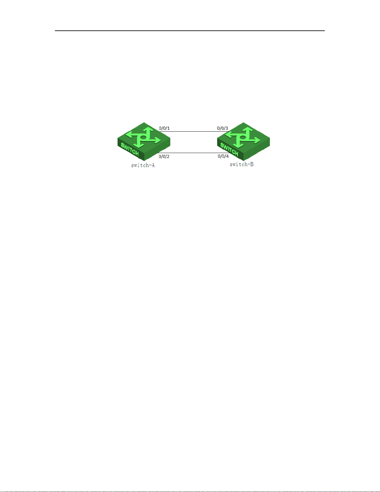
Link Aggregation Configuration
59
7.7 LACP Configuration Example
I. Network requirements
As shown in Figure 7-2, the link between switch-A and switch-B should be more reliable.
switch-A and switch-B should realize load-balance.
II. Network diagram
Figure 7-2 LACP network diagram
III. Configuration procedure
Create channel-group
#Configure switch-A
switch-A#configure terminal
switch-A(config)#channel-group 1
#Configure switch-B
switch-B#configure terminal
switch-B(config)#channel-group 1
Configure channel-group load-balance
#Configure switch-A
switch-A(config)#channel-group load-balance src-dst-mac
#Configure switch-B
switch-B(config)#channel-group load-balance src-dst-mac
Configure LACP system and port priority
#Configure switch-A
switch-A(config)#lacp system-priority 1024
switch-A(config)#interface range ethernet 0/0/1 to ethernet 0/0/2
switch-A(config-if-range)#lacp port-priority 64
switch-A(config-if-range)#exit
#Configure switch-B

Link Aggregation Configuration
60
switch-B(config)#lacp system-priority 2048
switch-B(config)#interface range ethernet 0/0/3 to ethernet 0/0/4
switch-B(config-if-range)#lacp port-priority 256
switch-B(config-if-range)#exit
Add port member for channel-group
1. Static
#Configure switch-A
switch-A(config)#interface range ethernet 0/0/1 to ethernet 0/0/2
switch-A(config-if-range)#channel-group 1 mode on
Remember to re-config mac-addresses associated with port e0/0/1
Remember to re-config mac-addresses associated with port e0/0/2
#Configure switch-B
switch-B(config)#interface range ethernet 0/0/3 to ethernet 0/0/4
switch-B(config-if-range)#channel-group 1 mode on
Remember to re-config mac-addresses associated with port e0/0/3
Remember to re-config mac-addresses associated with port e0/0/4
2. Dynamic
#Configure switch-A
switch-A(config)#interface range ethernet 0/0/1 to ethernet 0/0/2
switch-A(config-if-range)#channel-group 1 mode active
Remember to re-config mac-addresses associated with port e0/0/1
Remember to re-config mac-addresses associated with port e0/0/2
#Configure switch-B
switch-B(config)#interface range ethernet 0/0/3 to ethernet 0/0/4
switch-B(config-if-range)#channel-group 1 mode passive
Remember to re-config mac-addresses associated with port e0/0/3
Remember to re-config mac-addresses associated with port e0/0/4
Check the configuration
1)show lacp internal
#show lacp internal of switch-A
switch-A(config-if-range)#show lacp internal
Load balance: src-dst-mac

Link Aggregation Configuration
61
Channel: 1, static channel
Port State A-Key O-Key Priority Logic-port Actor-state
e0/0/1 bndl - - - 1 -
e0/0/2 bndl - - - 1 -
actor-state: activity/timeout/aggregation/synchronization
collecting/distributing/defaulted/expired
#show lacp internal of switch-A
switch-A(config-if-range)#show lacp internal
Load balance: src-dst-mac
Channel: 1, dynamic channel
Port State A-Key O-Key Priority Logic-port Actor-state
e0/0/1 bndl 2 2 64 1 10111100
e0/0/2 bndl 2 2 64 1 10111100
actor-state: activity/timeout/aggregation/synchronization
collecting/distributing/defaulted/expired
#show lacp internal of switch-B
switch-B(config-if-range)#show lacp internal
Load balance: src-dst-mac
Channel: 1, dynamic channel
Port State A-Key O-Key Priority Logic-port Actor-state
e0/0/3 bndl 2 2 256 3 00111100
e0/0/4 bndl 2 2 256 3 00111100
actor-state: activity/timeout/aggregation/synchronization
collecting/distributing/defaulted/expired
2)Show LACP neighbor
#Show LACP neighbor of switch-A
switch-A(config-if-range)#show lacp neighbor
Channel: 1

Link Aggregation Configuration
62
Local Port Key Pri ID Timeout Nei-state
e0/0/1 3 2 256 000a5a020305 82(90) 00111100
e0/0/2 4 2 256 000a5a020305 80(90) 00111100
nei-state: activity/timeout/aggregation/synchronization
collecting/distributing/defaulted/expired
#Show LACP neighbor of switch-B
switch-B(config-if-range)#show lacp neighbor
Channel: 1
Local Port Key Pri ID Timeout Nei-state
e0/0/3 1 2 64 000a5a010203 71(90) 10111100
e0/0/4 2 2 64 000a5a010203 69(90) 10111100
nei-state: activity/timeout/aggregation/synchronization
collecting/distributing/defaulted/expired
3)Show system ID
#Show switch-A system ID
switch-A(config-if-range)#show lacp sys-id
1024,000a5a010203
#Show switch-B system ID
switch-B(config-if-range)#show lacp sys-id
2048,000a5a020305
Delete port member from channel-group
#Configure switch-A
switch-A(config-if-range)#no channel-group 1
Remember to re-config mac-addresses associated with port e0/0/1
Remember to re-config mac-addresses associated with port e0/0/2
switch-A(config-if-range)#exit
#Configure switch-B
switch-B(config-if-range)#no channel-group 1
Remember to re-config mac-addresses associated with port e0/0/3
Remember to re-config mac-addresses associated with port e0/0/4
switch-B(config-if-range)#exit

Link Aggregation Configuration
63
Delete channel-group
#Configure switch-A
switch-A(config)#no channel-group 1
#Configure switch-B
switch-B(config)#no channel-group 1

Port Isolation Configuration
64
Operation
Command
Remarks
Enter global configuration
mode
configure terminal
Configure port isolation
isolate-port interface-number
Required
Chapter 8. Port Isolation
Configuration
8.1 Introduction to Port Isolation
To implement Layer 2 isolation, you can add different ports to different VLANs. However,
this will waste the limited VLAN resource. With port isolation, the ports can be isolated within
the same VLAN. Thus, you need only to add the ports to the isolation group to implement
Layer 2 isolation. This provides you with more secure and flexible networking schemes.
On the current device:
Currently, only one isolation group is supported on a device, which is created automatically
by the system as isolation group. The user cannot remove the isolation group or create other
isolation groups.
The number of the ports an isolation group can contain is total port number-1. Because
isolated ports are downlink ports. There should be at least one uplink port.
Note:
When a port in an aggregation group is configured as the member of isolation group,
the other ports of the aggregation group will not be downlink ports.
8.2 Port Isolation Configuration
8.2.1 Port Isolation Configuration
Add a port to port-isolation group. The isolated port members cannot communicate with
each other, but can only communicate with un-isolated port. Use no port-isolation command
to delete a port from the isolated group.
Table 8-1 Configure port isolation

Port Isolation Configuration
65
Operation
Command
Remarks
Show isolate-port configuration
show isolate-port
On any
configuration mode
8.2.2 Port-isolation Monitor and Maintenance
After finishing above configuration, user can check the configurations by command below.
Table 8-2 Port-isolation monitor and maintenance
8.3 Port-isolation Configuration Example
8.3.1 Port-isolation Configuration Example
I. Network requirements
User PC1,PC2,PC3 connect to switch e0/0/2,e0/0/3,e0/0/4. Switch connects to Internet
by e0/0/1. User PC1,PC2,PC3 need independent data exchange.
II. Networking diagram
III. Configuration procedure
Switch#configure terminal
Switch(config)#isolate-port ethernet 0/0/2 to ethernet 0/0/4
Add port isolation downlink port successfully.
Switch(config)#show isolate-port
Port isolation downlink port :
e0/0/2-e0/0/4

VLAN Configuration
66
Chapter 9. VLAN Configuration
9.1 VLAN Overview
Virtual Local Area Network (VLAN) groups the devices of a LAN logically but not physically
into segments to implement the virtual workgroups. IEEE issued the IEEE 802.1Q in 1999,
which was intended to standardize VLAN implementation solutions.
Through VLAN technology, network managers can logically divide the physical LAN into
different broadcast domains. Every VLAN contains a group of workstations with the same
demands. The workstations of a VLAN do not have to belong to the same physical LAN
segment.
With VLAN technology, the broadcast and unicast traffic within a VLAN will not be
forwarded to other VLANs, therefore, it is very helpful in controlling network traffic, saving
device investment, simplifying network management and improving security.
Figure 9-1 Vlan implementation
A VLAN can span across multiple switches, or even routers. This enables hosts in a VLAN
to be dispersed in a looser way. That is, hosts in a VLAN can belong to different physical
network segment.
Compared with the traditional Ethernet, VLAN enjoys the following advantages.
1) Broadcasts are confined to VLANs. This decreases bandwidth utilization and improves
network performance.
2) Network security is improved. VLANs cannot communicate with each other directly.
That is, a host in a VLAN cannot access resources in another VLAN directly, unless routers or
Layer 3 switches are used.
3) Network configuration workload for the host is reduced. VLAN can be used to group
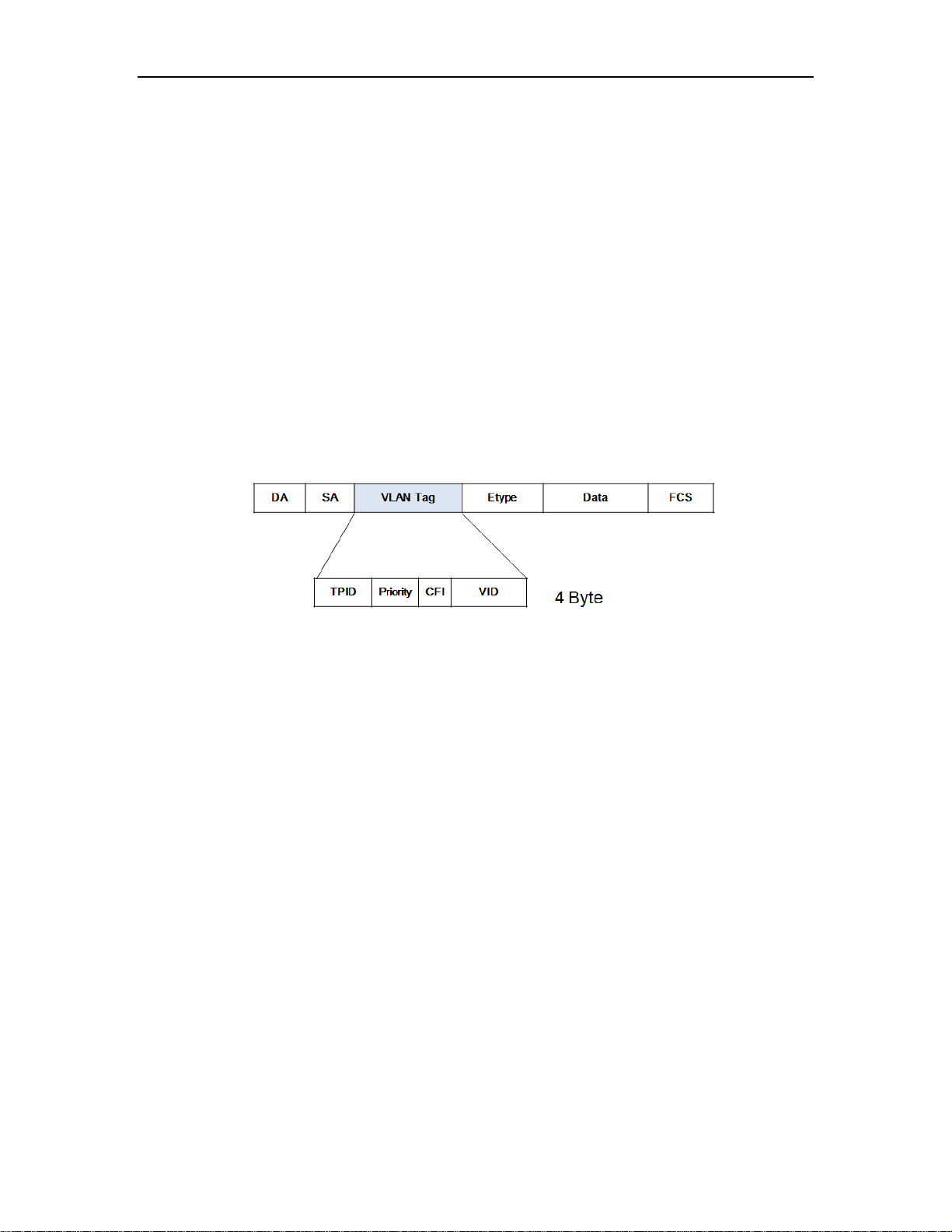
VLAN Configuration
67
specific hosts. When the physical position of a host changes within the range of the VLAN,
you need not change its network configuration.
9.2 VLAN Principles
VLAN tags in the packets are necessary for the switch to identify packets of different
VLANs. The switch works at Layer 2 (Layer 3 switches are not discussed in this chapter) and
it can identify the data link layer encapsulation of the packet only, so you can add the VLAN
tag field into only the data link layer encapsulation if necessary.
In 1999, IEEE issues the IEEE 802.1Q protocol to standardize VLAN implementation,
defining the structure of VLAN-tagged packets.
IEEE 802.1Q protocol defines that a 4-byte VLAN tag is encapsulated after the destination
MAC address and source MAC address to show the information about VLAN.
Figure 9-2 Format of VLAN tag
As shown in Figure 9-2, a VLAN tag contains four fields, including TPID (Tag Protocol
Identifier), priority, CFI (Canonical Format Indicator), and VID (VLAN ID).
TPID is a 16-bit field, indicating that this data frame is VLAN-tagged. By default, it is
0x8100.
Priority is a 3-bit field, referring to 802.1p priority. Refer to section “QoS & QoS profile” for
details.
CFI is a 1-bit field, indicating whether the MAC address is encapsulated in the standard
format in different transmission media. This field is not described in detail in this chapter.
VID (VLAN ID) is a 12-bit field, indicating the ID of the VLAN to which this packet belongs.
It is in the range of 0 to 4,095. Generally, 0 and 4,095 is not used, so the field is in the range of
1 to 4,094.
VLAN ID identifies the VLAN to which a packet belongs. When the switch receives an
un-VLAN-tagged packet, it will encapsulate a VLAN tag with the default VLAN ID of the
inbound port for the packet, and the packet will be assigned to the default VLAN of the
inbound port for transmission. For the details about setting the default VLAN of a port, refer to
section “02-Port Configuration”

VLAN Configuration
68
Port type
Ingress
Egress
Untagged
packet
Tagged packet
Access port
Receive it and
add a tag with
VID being
equal to PVID.
If VID of the
packet is equal
to the port
permitted VID,
receive it; if VID
is different,
discard it.
Strip the Tag and transmit the packet as
the VID of the packet is equal to the port
permitted VID
Hybrid port
If VID of the packet is equal to the port
permitted untag VID, remove the tag and
transmit it; If VID of the packet is equal to
the port permitted tag VID, keep the tag
and transmit it.
Trunk port
If VID of the packet is equal to the port
permitted VID, keep the tag and transmit
it.
9.3 802.1Q VLAN
9.3.1 VLAN Link Type of Ethernet Ports
An Ethernet port can operate in one of the three link types:
Access: An access port only belongs to one VLAN, normally used to connect user device.
Trunk: A trunk port can belong to more than one VLAN. It can receive/send packets from/to
multiple VLANs and is generally used to connect another switch. The packet sent from this
port can only be with tag label.
Hybrid: A hybrid port can belong to multiple VLANs, can receive or send packets for
multiple VLANs, used to connect either user or network devices. It allows packets of multiple
VLANs to be sent with or without the Tag label
9.3.2 Default VLAN
Details refer to 02-Port configuration.
9.3.3 Handling Packets
Different ports have different ways to handle the packet. Details are in Table 9-1
Table 9-1 Different port handles different packet

VLAN Configuration
69
Parameter
Default
Description
Existed VLAN
VLAN 1
The vlan-id argument ranges from 1 to
4,094.
VLAN 1 is the default VLAN of all ports.
VLAN description
/
VLAN description is characters ranged
from 1 to 32.
Port member of VLAN
All ports are the
members of VLAN 1.
Operation
Command
Description
Enter global configuration
mode
configure terminal
Create a vlan and enter
vlan configuration mode
VLAN vlan-list
If the VLAN to be created exists, enter
the VLAN mode directly. Otherwise,
create the VLAN first, and then enter the
VLAN mode.
Vlan-id allowed to configure is in the
range of 1 to 4094. Vlan-list can be in the
form of discrete number, a sequence
number, or the combination of discrete
and sequence number, discrete number
of which is separate by comma, and
sequence number of which is separate
by subtraction sign, such as: 2, 5, 8,
10-20.
Add port member to a
vlan
switchport ethenet
device-num/slot-num/portnum
Configure vlan
description
description vlan-name
By default, vlan description is empty.
Display the related
information about VLAN
show vlan vlan_id
Chapter 10. VLAN Configuration
10.1 Default VLAN Configuration
Table 10-1 Default VLAN configuration
10.2 Create and Modify VLAN
Switch supports 4094 VLANs.
Perform following commands in privilege mode.
Table 10.2 Create and modify VLAN

VLAN Configuration
70
Operation
Command
Description
Enter global configuration
mode
configure terminal
/
Enter vlan configuration mode
vlan vlan-list
/
Delete port member from
VLAN
no switchport { all |
ethernet port_list }
/
Display the related information
about VLAN
show vlan vlan_id
/
Operation
Command
Description
Enter global configuration mode
configure terminal
Delete VLAN
no vlan {vlan-list |all}
Display the related information
about VLAN
show vlan vlan_id
10.3 Delete Port Members from VLAN
Perform following commands in privilege mode.
Table 10-3 Delete port members from a VLAN
Note:
A port whose VLAN should not the default VLAN.
10.4 Delete VLAN
Perform following commands in privilege mode.
Table 10-4 Delete vlan
Note:
After perform no vlan all, system will delete all vlan except VLAN 1. In other words,
VLAN 1 cannot be deleted.
The VLAN to be removed cannot exist in the multicast group. So please remove the
related multicast group first.
10.5 VLAN Configuration Example
Networking Requirements
Create VLAN2 and VLAN3. Add GigabitEthernet0/0/1 and GigabitEthernet0/0/2 to VLAN2
and add GigabitEthernet0/0/3 and GigabitEthernet0/0/4 to VLAN3. Delete
GigabitEthernet0/0/1 to GigabitEthernet0/0/4 from VLAN1.

VLAN Configuration
71
Figure 10-1 Networking diagram
Networking configuration
! Create VLAN 2 and enter it.
Switch(config)# vlan 2
! Add Ethernet0/01 and Ethernet0/0/2 to VLAN2.
Switch(config-if-vlan)#switchport ethernet 0/0/1 ethernet 0/0/2
! Create VLAN 3 and enter it.
Switch(config)# vlan 3
! Add Ethernet0/0/3 and Ethernet0/0/4 to VLAN3.
Switch(config-if-vlan)#switchport ethernet 0/0/3 ethernet 0/0/4
! Set the default vlan of Ethernet0/0/1and Ethernet0/0/2
Switch(config)#interface range ethernet 0/0/1 to ethernet 0/0/2
Switch(config-if-range)# switchport default vlan 2
! Set the default vlan of Ethernet0/0/3 and Ethernet0/0/4
Switch(config)#interface range ethernet 0/0/3 to ethernet 0/0/4
Switch(config-if-range)# switchport default vlan 3
! Enter VLAN view and delete Ethernet0/0/1 to Ethernet0/0/4 from VLAN1.
Switch(config)#vlan 1
Switch(config-if-vlan)#no switchport ethernet 0/0/1 to ethernet 0/0/4

GVRP Configuration
72
Chapter 11. GVRP Configuration
11.1 Brief Introduction to GVRP
1. GARP
Generic Attribute Registration Protocol (GARP) provides a mechanism that allows
participants in a GARP application to distribute, propagate and register with other participants
in a bridged LAN that attributes specific to the GARP applications, such as the VLAN or
multicast address attribute.
GARP itself does not exist on a device as an entity. GARP-compliant application entities
are called a GARP application. It primarily applies to GVRP and GMRP. When a GARP
application entity is present on a port on your device, this port is regarded as a GARP
application.
The GARP mechanism allows the configuration of a GARP participant to propagate
throughout a LAN quickly. In GARP, a GARP participant registers or deregisters its attributes
with other participants by making or withdrawing declarations of attributes and at the same
time, based on received declarations or withdrawals handles attributes of other participants.
GARP participants exchange attributes primarily by sending the following three types of
messages:Join、Leave and LeaveAll.
I. Join to announce the willingness to register some attribute with other
participants.
II. Leave to announce the willingness to deregister with other participants.
LeaveAll to deregister all attributes. A LeaveAll message is sent upon expiration of a
LeaveAll timer, which starts upon the startup of a GARP application entity.
Together with Join messages and Leave messages help GARP participants complete
attribute registration and deregistration. All the attributes messages can forward to all
switches in the same network.
GARP application entities send protocol data units (PDU) with a particular multicast MAC
address as destination. Based on this address, a device can identify to which GARP
application, GARP for example, should a GARP PDU be delivered.
GARP is described in IEEE 802.1Q.
2. GVRP
GVRP is a GARP application. It functions based on the operating mechanism of GARP to
maintain and propagate dynamic VLAN registration information for the GVRP devices on the

GVRP Configuration
73
Configuration
Remark
Detailed
configuration
Configure GVRP
Startup GVRP
Required
11.2.2
Configure VLAN under
GVRP
required
11.3
Display and maintain GVRP
optional
11.3.1
Operation
Command
Remark
Enter global configuration
mode
configure terminal
-
Enable GVRP in global
configuration mode
gvrp
required
Enter port configuration
mode
interface ethernet device/slot/port
-
Enable GVRP in port
configuration mode
gvrp
required
network. It thus ensures that all GVRP participants on a bridged LAN maintain the same
VLAN registration information. The VLAN registration information propagated by GVRP
includes both manually configured local static entries and dynamic entries from other devices.
11.2 Configuring GVRP
11.2.1 Brief Introduction to GVRP Configuration
Table 11-1 GVRP configuration
11.2.2 Startup GVRP
Before enabling GVRP on a port, you must enable GVRP globally because it disables in
default.
Notes: you need to configure the port trunk to enable GVRP.
Table 11-2 Startup GVRP
11.3 Configuring VLAN Forwarded by GVRP
Obviously VLAN registration information forwarded by GVRP can be the local
configuration static VLAN, or be learned by GVRP dynamic protocols. But when the
administrator names, the permit VLANs can pass through the port to send GVRP packets.

GVRP Configuration
74
Operation
Command
Remark
Enter global configuration
mode
configure terminal
-
Configure VLAN forwarded by
GVRP
garp permit vlan vlan-list
required
Operation
Command
Remark
Show GVRP enable globally
show gvrp
Perform in any
configuration
mode
Show port enable maintained by
GVRP
show gvrp interface [ethernet
device/slot/port]
Show GVRP permit VLAN
show garp permit vlan
Table 11-3 Configure VLAN forwarded by GVRP
11.3.1 Displaying and Debugging
You can show the configuration through below commands when you finish all above
configuration.
Table 11-4 Displaying GVRP and debugging
11.3.2 GVRP Configuration Examples
As below, S1 and S3 forward respective static VLAN information to S2 by GVRP protocol,
S2 forwards to each other with local static and learning VLAN from GVRP. At the end, S1, S2,
S3 can share the dynamic VLAN information.
Figure 11.1 Network
Figure 11-1 Configuration procedure:
!Configure S1
***************************************************************
!Preparation before configure
Switch(config)#vlan 2,3,4
Switch(config-if-vlan)#switchport ethernet 0/0/1
Add VLAN port successfully.
Switch(config-if-vlan)#interface e 0/0/1
Switch(config-if-ethernet-0/0/1)#switchport mode trunk
Switch(config-if-ethernet-0/0/1)#exit
!Configure GVRP

GVRP Configuration
75
Switch(config)#gvrp
Turn on GVRP successfully.
Switch(config)#garp permit vlan 2,3,4
Switch(config)#interface e 0/0/1
Switch(config-if-ethernet-0/0/1)#gvrp
Switch(config-if-ethernet-0/0/1)#exit
!Verify GVRP configuration
Switch(config)#show gvrp
GVRP state : enable
Switch(config)#show gvrp interface ethernet 0/0/1
port GVRP status
e0/0/1 enable
Total entries: 1.
Switch(config)#show garp permit vlan
VLAN 1 is Garp default permit VLAN
Other Garp permit VLAN : 2-4
***************************************************************
!Configure S2
***************************************************************
!Preparation before configure
Switch(config)#vlan 5,6
Switch(config-if-vlan)#switchport ethernet 0/0/2
Add VLAN port successfully.
Switch(config-if-vlan)#switchport ethernet 0/0/3
Add VLAN port successfully.
Switch(config-if-vlan)#exit
Switch(config)#interface range ethernet 0/0/2 to ethernet 0/0/3
Switch(config-if-range)# switchport mode trunk
Switch(config-if-range)#exit
!Configure GVRP
Switch(config)#gvrp
Turn on GVRP successfully
Switch(config)#interface range ethernet 0/0/2 to ethernet 0/0/3
Switch(config-if-range)#gvrp.
Switch(config)#garp permit vlan 5,6
!Verify GVRP configuration

GVRP Configuration
76
Switch(config)#show gvrp
GVRP state : enable
Switch(config)#show gvrp interface ethernet 0/0/2 ethernet 0/0/3
port GVRP status
e0/0/2 enable
e0/0/3 enable
Total entries: 2.
Switch(config)#show garp permit vlan
VLAN 1 is Garp default permit VLAN
Other Garp permit VLAN : 5-6
***************************************************************
!Configure S3
***************************************************************
!Preparation before configure
Switch(config)#vlan 7,8
Switch(config-if-vlan)#switchport ethernet 0/0/4
Add VLAN port successfully.
Switch(config-if-vlan)#interface e 0/0/4
Switch(config-if-ethernet-0/0/4)#switchport mode trunk
!Configure GVRP
Switch(config)#gvrp
Turn on GVRP successfully.
Switch(config)#interface e 0/0/4
Switch(config-if-ethernet-0/0/4)#gvrp
Switch(config)#garp permit vlan 7,8
!Verify GVRP configuration
Switch(config)#show gvrp
GVRP state : enable
Switch(config)#show gvrp interface ethernet 0/0/4
port GVRP status
e0/0/4 enable
Total entries: 1.
Switch(config)#show garp permit vlan
VLAN 1 is Garp default permit VLAN

GVRP Configuration
77
Other Garp permit VLAN : 7-8
***************************************************************
After finishing the configuration, you can show VLAN to check the VLAN register
information learned by GVRP
!VLAN5,6,7,8 is learned by GVRP when showing S1 VLAN information
Switch(config)#show vlan
show VLAN information
VLAN ID : 1
VLAN status : static
VLAN member : e0/0/1-e0/2/2
Static tagged ports : e0/0/1
Static untagged Ports : e0/0/2-e0/2/2
Dynamic tagged ports :
show VLAN information
VLAN ID : 2
VLAN status : static
VLAN member : e0/0/1.
Static tagged ports : e0/0/1.
Static untagged Ports :
Dynamic tagged ports :
show VLAN information
VLAN ID : 3
VLAN status : static
VLAN member : e0/0/1.
Static tagged ports : e0/0/1.
Static untagged Ports :
Dynamic tagged ports :
show VLAN information
VLAN ID : 4
VLAN status : static
VLAN member : e0/0/1.
Static tagged ports : e0/0/1.

GVRP Configuration
78
Static untagged Ports :
Dynamic tagged ports :
show VLAN information
VLAN ID : 5
VLAN status : dynamic
VLAN member : e0/0/1
Static tagged ports :
Static untagged Ports :
Dynamic tagged ports : e0/0/1
show VLAN information
VLAN ID : 6
VLAN status : dynamic
VLAN member : e0/0/1
Static tagged ports :
Static untagged Ports :
Dynamic tagged ports : e0/0/1
show VLAN information
VLAN ID : 7
VLAN status : dynamic
VLAN member : e0/0/1
Static tagged ports :
Static untagged Ports :
Dynamic tagged ports : e0/0/1
show VLAN information
VLAN ID : 8
VLAN status : dynamic
VLAN member : e0/0/1
Static tagged ports :
Static untagged Ports :
Dynamic tagged ports : e0/0/1
Total entries: 8 vlan.

ARP Configuration
79
Chapter 12. ARP Configuration
12.1 ARP Overview
12.1.1 ARP Function
Address Resolution Protocol (ARP) is used to resolve an IP address into a data link layer
address.
An IP address is the address of a host at the network layer. To send a network layer packet
to a destination host, the device must know the data link layer address (such as the MAC
address) of the destination host. To this end, the IP address must be resolved into the
corresponding data link layer address.
Unless otherwise stated, the data link layer addresses that appear in this chapter refer to
the 48-bit Ethernet MAC addresses.
ARP Address Resolution Process as below:
Suppose that Host A and Host B are on the same subnet and that Host A sends a
message to Host B, as show in Figure 12-1. The resolution process is as follows:
1) Host A looks in its ARP mapping table to see whether there is an ARP entry for Host B. If
Host A finds it, Host A uses the MAC address in the entry to encapsulate the IP packet into a
data link layer frame and sends the frame to Host B.
2) If Host A finds no entry for Host B, Host A buffers the packet and broadcasts an ARP
request, in which the source IP address and source MAC address are respectively the IP
address and MAC address of Host A and the destination IP address and MAC address are
respectively the IP address of Host B and an all-zero MAC address. Because the ARP
request is sent in broadcast mode, all hosts on this subnet can receive the request, but only
the requested host (namely, Host B) will process the request.
3) Host B compares its own IP address with the destination IP address in the ARP request.
If they are the same, Host B saves the source IP address and source MAC address into its
ARP mapping table, encapsulates its MAC address into an ARP reply, and unicasts the reply
to Host A.
4) After receiving the ARP reply, Host A adds the MAC address of Host B into its ARP
mapping table for subsequent packet forwarding. Meanwhile, Host A encapsulates the IP
packet and sends it out.

ARP Configuration
80
Figure 12-1 ARP address resolution process
When Host A and Host B are not on the same subnet, Host A first sends an ARP request to
the gateway. The destination IP address in the ARP request is the IP address of the gateway.
After obtaining the MAC address of the gateway from an ARP reply, Host A encapsulates the
packet and sends it to the gateway. Subsequently, the gateway broadcasts the ARP request,
in which the destination IP address is the one of Host B. After obtaining the MAC address of
Host B from another ARP reply, the gateway sends the packet to Host B.
12.1.2 ARP Message Format
Figure 12-2 ARP Message Format
The following explains the fields in Figure 12-2.
Hardware type: This field specifies the hardware address type. The value “1” represents
Ethernet.
Protocol type: This field specifies the type of the protocol address to be mapped. The
hexadecimal value “0x0800” represents IP.
Hardware address length and protocol address length: They respectively specify the
length of a hardware address and a protocol address, in bytes. For an Ethernet address, the

ARP Configuration
81
value of the hardware address length field is "6”. For an IP(v4) address, the value of the
protocol address length field is “4”.
OP: Operation code. This field specifies the type of ARP message. The value “1”
represents an ARP request and “2” represents an ARP reply.
Sender hardware address: This field specifies the hardware address of the device sending
the message.
Sender protocol address: This field specifies the protocol address of the device sending
the message.
Target hardware address: This field specifies the hardware address of the device the
message is being sent to.
Target protocol address: This field specifies the protocol address of the device the
message is being sent to.
12.2 Configuring ARP Attack Spoofing
12.2.1 Brief Introduction to ARP Spoofing
ARP provides no security mechanism and thus is prone to network attacks. An attacker
can construct and send ARP packets, thus threatening network security.
A forged ARP packet has the following characteristics:
The sender MAC address or target MAC address in the ARP message is inconsistent with
the source MAC or destination MAC address in the Ethernet frame.
The mapping between the sender IP address and the sender MAC address in the forged
ARP message is not the true IP-to-MAC address binding of a valid client.
ARP attacks bring many malicious effects. Network communications become unstable,
users cannot access the Internet, and serious industrial accidents may even occur. ARP
attacks may also intercept accounts and passwords of services such as games, network
banks, and file services.
12.2.2 ARP Anti-Spoofing Protection
ARP spoofing attacks to protection, the key is to identify and prohibit forwarding spoofed
ARP packets. From the principle of ARP spoofing, we can see, to prevent ARP spoofing
attack requires two ways, first to prevent the virus disguised as the gateway host, it will cause
the entire segment of the user can not access; followed by preventing the virus from the host
masquerade as another host, eavesdropping data or cause the same network segment can’t
communicate between the individual host.

ARP Configuration
82
Step
Command
Operation
step1
configure terminal
Enter global configuration mode
Step2
arp anti-spoofing
Enable ARP anti-spoofing
Step3
arp anti-spoofing unknown
{diacard | flood}
Configure the method of unknown
static ARP packet
Step4
end
return to privilege mode
Step5
copy running-config
startup-config
save modified configuration
S6424-S2C2 switches provide active defense ARP spoofing function, in practical
applications, the network hosts the first communication, the switch will record the ARP table
entries, entries in the message of the sender IP, MAC, VID, and port correspondence.
To prevent the above mentioned ARP attacks, S6424-S2C2 launches a comprehensive
ARP attack protection solution.
An access switch is a critical point to prevent ARP attacks, as ARP attacks generally arise
from the host side. To prevent ARP attacks, the access switches must be able to
Establish correct ARP entries, detect and filter out forged ARP packets, and ensure the
validity of ARP packets it forwards
Suppress the burst impact of ARP packets.
After configuring the access switches properly, you do not need to deploy ARP attack
protection configuration on the gateway. This relieves the burden from the gateway.
If the access switches do not support ARP attack protection, or the hosts are connected to
a gateway directly, the gateway must be configured to
Create correct ARP entries and prevent them from being modified.
Suppress the burst impact of ARP packets or the IP packets that will trigger sending of
ARP requests.
The merits of configuring ARP attack protection on the gateway are that this gateway
configuration hardly affects the switches and can properly support the existing network, thus
effectively protecting user investment
12.2.3 Configuring Anti-Spoofing
Table 12-1 Configure anti-spoofing

ARP Configuration
83
Step
Command
Operation
step1
configure terminal
Enter global configuration mode
step2
arp anti-spoofing valid-check
Configure ARP Packet Source MAC
Address Consistency Check
step3
show arp anti-spoofing
validation operation
step4
end
return to privilege mode
step5
copy running-config
startup-config
save modified configuration
Function
Default
arp anti-spoofing
disable
Configure ARP Packet Source MAC Address
Consistency Check
enable
arp anti-spoofing unknown {diacard | flood}
discard
Command
Operation
show arp anti-spoofing
Display the status of anti-spoofing
show mac-address-table blackhole
Display users whether add into black hole
12.2.4 Configuring ARP Packet Source MAC Address Consistency Check
This feature enables a gateway device to filter out ARP packets with a source MAC
address in the Ethernet header different from the sender MAC address in the message body,
so that the gateway device can learn correct ARP entries.
By default, system disables gateway spoofing.
Table 12-2 Configure ARP Packet Source MAC Address Consistency Check
12.2.5 Configuring Default of Anti-Spoofing
Table 12-3 Configure default of anti-spoofing
12.2.6 Displaying and Maintain Anti-Spoofing
Table 12-4 Configure default of anti-spoofing
12.3 Configuring against ARP Flood
12.3.1 ARP Flood
Flood attacks are based on the principle of the general flow of a large number of attack
packets in the network equipment such as routers, switches, and servers, leading to depletion

ARP Configuration
84
Command
Operation
Remark
Enter global
configuration mode
configure terminal
Enable ARP flooding
arp anti-flood
required
Configure safety trigger
arp anti-flood threshold threshold
optional
of network equipment, leaving the CPU down the network.
Flood attacks are based on the principle of the general flow of a large number of attack
packets in the network equipment such as routers, switches, and servers, leading to depletion
of network equipment, leaving the CPU down the network.
12.3.2 Configuring against ARP Flood
ARP flood attack is aimed mainly at the impact of network device's CPU, the core CPU
resources leading to depletion. To defend this type of attack, the switch must determine in
advance and to prohibit flood packet forwarding.
S6424-S2C2's ARP anti-flood function to identify each ARP traffic, according to the ARP
rate setting security thresholds to determine whether the ARP flood attack, when a host's ARP
traffic exceeds a set threshold, the switch will be considered a flood attack , immediately
pulled into the black host of the virus, banned from the host and all packet forwarding.
In order to facilitate the management of the network administrator to maintain,
S6424-S2C2, while the automatic protection will be saved in the system log related to alarms.
For disabled users, administrators can set automatic or manual recovery.
In the S6424-S2C2 switch on the entire process is as follows:
Enable ARP anti-flood function will be broadcast ARP packets received on the CPU,
according to an ARP packet source MAC address to identify the different streams.
Set security ARP rate, if the rate exceeds the threshold, the switch that is ARP attack.
If you select the above command deny-all, when an ARP traffic exceeds the threshold set,
the switch will determine the source MAC address, the MAC address to the black hole list of
addresses to ban this address to forward all subsequent messages.
If you select the above command deny-arp, ARP traffic when more than a set threshold,
the switch will be judged based on the source MAC address, the address against all
subsequent handling of ARP packets.
For recovery to be disabled in the user's forwarding, administrators can set up automatic
or manual recovery time in two ways.
12.3.3 Configuring against ARP Flood
Table 12-5 Configure against ARP flood

ARP Configuration
85
threshold
By default, the safety
trigger threshold 16PPS
Configure approach for
the attacker
arp anti-flood action {deny-arp|deny-all}
threshold threshold
optional
By default,for the
attacker's approach to
deny ARP
Configure automatically
banned user recovery
time
arp anti-flood recover-time time
optional
Configurable time range
is <0-1440> minutes, set
to 0, said to be manually
restored.
By default,the user
automatically banned
recovery time of 10
minutes.
Banned user manual
resume forwarding.。
arp anti-flood recover {H:H:H:H:H:H | all}
optional
Operation
Command
Remark
Display ARP anti-flood configuration and
attackers list
show arp anti-flood
Perform either of the
commands
12.3.4 Displaying and Maintain against ARP Flood
Table 12-6

IGMP Snooping
86
Configuration Task
Remark
Detailed
configuration
IGMP
Snooping
basic
configuration
Enable IGMP Snooping
required
3.2.2
Modify and
optimize
IGMP
Snooping
configuration
Configure IGMP Snooping multicast interface
aging time
optional
3.2.3
Configure IGMP Snooping
max-response-time
optional
3.2.3
Configure IGMP Snooping interface fast-leave
optional
3.2.4
Configure the number of the multicast group
allowed learning
optional
3.2.5
Configure IGMP-Snooping multicast learning
strategy
optional
3.2.6
Configure IGMP-Snooping CSS
optional
3.2.7
Configure route-port
optional
3.2.8
Configure IGMP Snooping multicast VLAN
optional
3.2.9
Configure port record host MAC
optional
3.2.10
Configure port whether waive research
optional
3.2.11
Chapter 13. IGMP Snooping
13.1 Brief Introduction to IGMP Snooping
IGMP (Internet Group Management Protocol) is a part of IP protocol which is used to
support and manage the IP multicast between host and multicast router. IP multicast allows
transferring IP data to a host collection formed by multicast group. The relationship of
multicast group member is dynamic and host can dynamically add or exit this group to reduce
network load to the minimum to realize the effective data transmission in network.
IGMP Snooping is used to monitor IGMP packet between host and routers. It can
dynamically create, maintain, and delete multicast address table according to the adding and
leaving of the group members. At that time, multicast frame can transfer packet according to
his own multicast address table.
13.2 IGMP Snooping Configuration
13.2.1 Brief Configuration of IGMP Snooping
Table 13-1 Brief configuration of IGMP Snooping

IGMP Snooping
87
packets or not
Configure port whether waive report packets
or not
optional
3.2.12
Configure multicast preview
optional
3.2.13
Configure IGMP Snooping profile name list
optional
3.2.14
Display and maintain IGMP Snooping
optional
3.2.15
Command
Operation
Remark
Enter global configuration mode
configure terminal
Enable IGMP Snooping
igmp-snooping
Command
Operation
Remark
Enter global configuration mode
configure terminal
-
Configure IGMP Snooping
multicast interface aging time
igmp-snooping
host-aging-time time
optional
By default, dynamic
interface aging time
is300S
Configure maximum leave time
igmp-snooping
max-response-time time
optional
by default, maximum
leave time is 10S
13.2.2 Enable IGMP Snooping
Table 13-2 Brief configuration of IGMP Snooping
13.2.3 Configuring IGMP Snooping Timer
Table 13-3 Configure IGMP Snooping timer
13.2.4 Configuring Port Fast-Leave
Under normal circumstances, IGMP-Snooping on IGMP leave message is received
directly will not remove the port from the multicast group, but to wait some time before the port
from the multicast group.
Enabling quickly delete function, IGMP-Snooping IGMP leave packet received, directly to
the port from the multicast group. When the port is only one user, can be quickly removed to
save bandwidth.

IGMP Snooping
88
Command
Operation
Remark
Enter global configuration mode
configure terminal
-
Enter port configuration
interface ethernet
interface-num
-
Configure port fast-leave
igmp-snooping fast-leave
optional
By default, port fast-leave
disables
Command
Operation
Remark
Enter global configuration mode
configure terminal
-
Enter port configuration
interface ethernet
interface-num
-
Configure the number of the
multicast group allowed
learning
igmp-snooping group-limit
number
optional
By default, the number of the
multicast group allowed learning
is NUM_MULTICAST_GROUPS
Table 13-4 Configure port fast-leave
13.2.5 Configuring Number of Multicast Group Allowed Learning
Use igmp-snooping group-limit command to configure the number of the multicast group
allowed learning.
Table 13-5 Configure the number of the multicast group allowed learning
13.2.6 Configuring IGMP Snooping Querier
In an IP multicast network running IGMP, a multicast router or Layer 3 multicast switch is
responsible for sending IGMP general queries, so that all Layer 3 multicast devices can
establish and maintain multicast forwarding entries, thus to forward multicast traffic correctly
at the network layer. his router or Layer 3 switch is called IGMP querier.
However, a Layer 2 multicast switch does not support IGMP, and therefore cannot send
general queries by default. By enabling IGMP Snooping on a Layer 2 switch in a VLAN where
multicast traffic needs to be Layer-2 switched only and no multicast routers are present, the
Layer 2 switch will act as the IGMP Snooping querier to send IGMP queries, thus allowing
multicast forwarding entries to be established and maintained at the data link layer.

IGMP Snooping
89
Command
Operation
remark
Enter global
configuration mode
configure terminal
-
Configuration is not black
and white list in the
multicast group to learn
the rules of the default
igmp-snooping {permit | deny}
{group all | vlan vid}
optional
By default, not black and white list
in the multicast group to learn the
rules for the learning of all
multicast group
Enter port configuration
interface ethernet interface-num
-
Configure the port
multicast black list
igmp-snooping {permit | deny}
group-range MAC multi-count
num vlan vid
optional
Configure the port to learn (not
learn) VID of the start of
continuous num mac multicast
groups
igmp-snooping {permit | deny}
group MAC vlan vid
optional
By default, any multicast group
are not black and white list are
added
Operation
Command
Remarks
Enter global configuration mode
configure terminal
-
Open the IGMP-Snooping querier
igmp-snooping querier
Configuring VLAN general query
messages
igmp-snooping querier-vlan vid
Optional
Configured to send general query
message interval
igmp-snooping query-interval interval
Optional
Configuration is generally the
maximum query response time of
message
igmp-snooping query-max-respond time
Optional
Configured to send general
inquiries packet source IP address
igmp-snooping general-query source-ip IP
Optional
Table 13-6 Configure IGMP Snooping querier
13.2.7 Configuring IGMP Snooping Multicast Learning Strategy
Configured multicast learning strategies, the administrator can control the router only to
learn the specific multicast group. If a multicast group is added to the blacklist, then the router
will not learn the multicast group; the contrary, in the white list in the router can learn multicast
group.
Table 13-7 Configuring IGMP Snooping multicast learning strategy
13.2.8 Configuring IGMP Snooping Router-Port
You can configure the router port will be automatically added to the dynamic IGMP

IGMP Snooping
90
Operation
Command
Remarks
Enter global configuration
mode
configure terminal
Configure hybrid routing port
igmp-snooping route-port forward
Optional
Configure dynamic routing
port aging time
igmp-snooping router-port-age {on | off |
age-time}
Optional
Configure static routing port
igmp-snooping route-port vlan vid interface {All |
ethernet interface-num}
Optiona
Operation
Command
Remarks
Enter global configuration mode
configure terminal
-
Enter port configuration mode
interface ethernet interface-num
-
Configure IGMP Snooping port
multicast VLAN
igmp-snooping multicast vlan vid
Optional
Operation
Command
Remarks
Enter global configuration mode
configure terminal
-
Enter port configuration mode
interface ethernet interface-num
-
Configure the host port record
MAC
igmp-snooping record-host
Optional
Snooping Multicast learn to make routing port also has a multicast packet forwarding
capability.
When the switch receives a host membership report sent packets, the port will be
forwarded to the route.
Table 13-8 Configuring Routing port
13.2.9 Configuring IGMP Snooping Port Multicast VLAN
Multicast VLAN on the port function, regardless of the port receiving the IGMP messages
belong to which VLAN, the switch will be modified as a multicast VLAN.
Table 13-9 Configure IGMP Snooping port multicast VLAN
13.2.10 Configuring Host Port Record MAC Functions
When this feature is enabled on the port, the switch will record the source packet IGMP
report MAC address.
Table 13-10 Configure the host port record MAC functions

IGMP Snooping
91
Operation
Command
Remarks
Enter global configuration mode
configure terminal
-
Enter port configuration mode
interface ethernet interface-num
-
Discard the query message to the
configuration port
igmp-snooping drop query
Optional
Configure the port to receive the
query message
no igmp-snooping drop query
Optional
Operation
Command
Remarks
Enter global configuration mode
configure terminal
-
Enter port configuration mode
interface ethernet interface-num
-
Configure the port discarded
packets report
igmp-snooping drop report
Optional
Configure the port to receive a
report with
no igmp-snooping drop report
Optional
13.2.11 Configuring Port of Dropped Query Packets or Not
When this feature is enabled on a port, the switch drops the IGMP query message. Default
port to receive all IGMP packets.
Table 13-11 Configure port of dropped query packets or not
13.2.12 Configuring Port of Discarded Packets Report or Not
When this feature is enabled on a port, the switch drops the IGMP report message. Default
port to receive all IGMP packets.
Table 13-12 Configure port of discarded packets report or not
13.2.13 Configuring Multicast Preview
Multicast IGMP Snooping provides preview feature, users can configure the multicast
channel preview, you can configure a single multicast length preview, preview interval,
duration, and reset to allow preview times.

IGMP Snooping
92
Operation
Command
Remarks
Enter global configuration mode
configure terminal
-
Configuring Multicast preview
igmp-snooping preview
-
Configure multicast channel
preview
igmp-snooping preview group-ip IP vlan vid
interface ethernet interface-num
Optional
Configuration when the long single
preview, preview interval, duration
and allows preview preview reset
the number of
igmp-snooping preview {time-once time-once
time-interval time-interval time-reset time-reset
permit-times preview-times }
Optional
Operation
Command
Remarks
Enter global configuration mode
configure terminal
-
Create a profile, and enter profile
configuration mode
igmp-snooping profile profile-id
Configuration profile types
profile limit {permit | deny}
Optional
Configuration profile ip range
ip range start-ip end-ip [vlan vlan-id]
Optional
Range of configuration profile
mac
mac range start-mac end-mac [vlan vlan-id]
Optional
Enter port configuration mode
interface ethernet interface-num
-
Reference configuration profile
igmp-snooping profile refer profile-list
Optional
Table 13-13 Configure multicast preview
13.2.14 Configuring Profile of Black and White List
IGMP Snooping provides the way black and white list feature profile, first in global
configuration mode to create a number of profiles, and then the port configuration mode to
configure the port reference profile list. Users can configure the IGMP Snooping profile of the
type and scope, which refers to the type of permit / deny, you can use the multicast IP address
range or MAC address to configure. IGMP Snooping profile only the port referenced to take
effect, the configuration port reference profile, the more the type of profile must be the same
between that port can only refer to the same type (permit or deny) the profile. When the port is
referenced permit the profile, the profile can only learn the definition of the corresponding
multicast group; when the port reference deny the profile, the profile can be defined in
addition to learning outside of all multicast group; when the port does not refer to any profile,
in accordance with Normally learning multicast group.
Table 13-14 Configure profile of black and white list
13.2.15 Displaying and Maintenance of IGMP Snooping
After completing the above configuration, can use the following command to view
configuration.

IGMP Snooping
93
Operation
Command
Remarks
See the related configuration IGMP
Snooping
show igmp-snooping
Performs either
of the
commands
See dynamic routing port
show igmp-snooping router-dynamic
Display static router port configuration
show igmp-snooping router-static
Display Record in host MAC
show igmp-snooping record-host
[interface ethernet interface-num]
Display information about multicast
preview
show igmp-snooping preview
Display the current state of multicast
channel preview
show igmp-snooping preview status
Display profile configuration
information
show igmp-snooping profile [interface
ethernet interface-num] [profile-list]
Display multicast group
show multicast [interface ethernet
interface-num]
S-switch-A
Ethernet0/0/3
Ethernet0/0/2
Host-A
Host-B
Host-C
Ethernet0/0/4
Table 13-15 Configure displaying and maintenance of IGMP Snooping
13.3 IGMP Snooping Configuration Examples
IGMP Snooping configuration examples as below:
Figure 13-1

IGMP Snooping
94
1. Network requirements
As shown in the figure 1-1,Host-A, Host-B, Host-C hosts separately belong to VLAN2,
VLAN3, VLAN4.Three hosts separately receive the data of the multicast address 224.0.1.1~
224.0.1.3 per configuring.
2. Configuration steps
Configuring S-switch-A
#Configure VLAN2 to 4,and add the ports separately into VlAN2,3,4 of Ethernet0/0/1,
Ethernet0/0/2 and Ethernet0/0/3.
S-switch-A(config)#vlan 2
S-switch-A(config-if-vlan)#switchport ethernet 0/0/1
S-switch-A(config-if-vlan)#exit
S-switch-A(config)#vlan 3
S-switch-A(config-if-vlan)#switchport ethernet 0/0/2
S-switch-A(config-if-vlan)#exit
S-switch-A(config)#vlan 4
S-switch-A(config-if-vlan)#switchport ethernet 0/0/3
S-switch-A(config-if-vlan)#exit
#Enable igmp snooping
S-switch-A(config)#igmp-snooping
When Host-A, Host-B, Host-C forward IGMP report to S-switch-A,S-switch-A will learn
corresponding multicast table entry port ;When the Multicast Source Router send igmp query
time to the S-switch-A message, S-switch-A will learn the appropriate router port entry.
Show the switch learned multicast group
S-switch-A(config)#show multicast
show multicast table information
MAC Address : 01:00:5e:00:01:01
VLAN ID : 2
Static port list :.
IGMP port list : e0/0/1
Dynamic port list :
MAC Address : 01:00:5e:00:01:02
VLAN ID : 3
Static port list :.

IGMP Snooping
95
IGMP port list : e0/0/2
Dynamic port list :
MAC Address : 01:00:5e:00:01:03
VLAN ID : 4
Static port list :
IGMP port list : e0/0/3.
Dynamic port list :
Total entries: 3 .
S-switch-A(config)#show igmp-snooping router-dynamic
Port VID Age Type
e0/0/4 2 284 { STATIC }
e0/0/4 3 284 { STATIC }
e0/0/4 4 284 { STATIC }
Total Record: 3
When Multicast Source Router sends 224.0.1.1-224.0.1.3 multicast serve data flow,
S-switch-A will forward corresponding to Host-A, Host-B, Host-C.
Static multicast configuration examples:
Configuration steps:
Configuring S-switch-A
#configure VLAN 2 to 4,and add the ports into VLAN2,3,4 of Ethernet0/0/1, Ethernet0/0/2
and Ethernet0/0/3.
S-switch-A(config)#vlan 2
S-switch-A(config-if-vlan)#switchport ethernet 0/0/1
S-switch-A(config-if-vlan)#exit
S-switch-A(config)#vlan 3
S-switch-A(config-if-vlan)#switchport ethernet 0/0/2
S-switch-A(config-if-vlan)#exit
S-switch-A(config)#vlan 4
S-switch-A(config-if-vlan)#switchport ethernet 0/0/3
S-switch-A(config-if-vlan)#exit

IGMP Snooping
96
#Add the ports into the VLAN2 to VLAN4 of Ethernet0/0/4,configure Ethernet0/0/4 as
static router port.
S-switch-A(config)#vlan 2-4
S-switch-A(config-if-vlan)#switchport ethernet 0/0/4
S-switch-A(config-if-vlan)#exit
S-switch-A(config)#igmp-snooping route-port vlan 2 interface ethernet 0/0/4
S-switch-A(config)#igmp-snooping route-port vlan 3 interface ethernet 0/0/4
S-switch-A(config)#igmp-snooping route-port vlan 4 interface ethernet 0/0/4
#configure static multicast group
S-switch-A(config)#multicast mac-address 01:00:5e:00:01:01 vlan 2
S-switch-A(config)#multicast mac-address 01:00:5e:00:01:01 vlan 2 interface ethernet
0/0/1
S-switch-A(config)#multicast mac-address 01:00:5e:00:01:02 vlan 3
S-switch-A(config)#multicast mac-address 01:00:5e:00:01:02 vlan 3 interface ethernet
0/0/2
S-switch-A(config)#multicast mac-address 01:00:5e:00:01:03 vlan 4
S-switch-A(config)#multicast mac-address 01:00:5e:00:01:03 vlan 4 interface ethernet
0/0/3
Show the switch learned multicast groups
S-switch-A(config)#show multicast
show multicast table information
MAC Address : 01:00:5e:00:01:01
VLAN ID : 2
Static port list :.e0/0/1
IGMP port list :
Dynamic port list :
MAC Address : 01:00:5e:00:01:02
VLAN ID : 3
Static port list : e0/0/2
IGMP port list :
Dynamic port list :
MAC Address : 01:00:5e:00:01:03

IGMP Snooping
97
VLAN ID : 4
Static port list : e0/0/3
IGMP port list :
Dynamic port list :
Total entries: 3 .
S-switch-A(config)#show igmp-snooping router-static
Port VID Age Type
e0/0/4 2 no age { STATIC }
e0/0/4 3 no age { STATIC }
e0/0/4 4 no age { STATIC }
Total Record: 3
When Multicast Source Router sends 224.0.1.1-224.0.1.3 multicast serve data flow
S-switch-A will forward corresponding to Host-A, Host-B, Host-C.

GMRP Configuration
98
Operation
Command
Remark
Enter globally configuration mode
configure terminal
-
Enable GMRP in global configuration
mode
gmrp
required
Enter port configuration
interface
ethernet device/slot/port
Enable GMRP in port configuration
mode
gmrp
required
Chapter 14. GMRP Configuration
14.1 Brief Introduction to GMRP
GMRP (GARP Multicast Registration Protocol) is a kind of application of GARP (Generic
Attribute Registration Protocol), which is based on GARP working mechanism to maintain the
dynamic multicast register information in switch. All switches supported GMRP can receive
multicast register information from other switches and upgrade local multicast register
information dynamically and transfer it to other switches to make the consistency of multicast
information of devices supported GMRP in the same switching network. Multicast register
information transferred by GMRP includes local manual configuration of static multicast
register information and the dynamic multicast register information of other switch
14.2 GMRP Configuration
14.2.1 Enabling GMRP
Enable GMRP needs in both globally and port configuration. By default, GMRP disable in
both globally and port configuration.
Table 14-1 Enable GMRP
14.2.2 Add Requisite Static Route Forwarded by GMRP
It forwards dynamically broadcast learning from GMRP when startup GMRP, but it is
necessary for administrator to configure manually when GMRP forwards local static
broadcast.

GMRP Configuration
99
Operation
Command
Remark
Enter globally configuration mode
configure terminal
-
Add requisite static route forwarded by
GMRP
garp permit multicast
mac-address mac vlan
vid
required
Operation
Command
Remark
display GMRP in globally configuration mode
show gmrp
Perform either of the
commands
Display GMRP in port configuration mode
show gmrp interface
[ethernet interface-nu
m]
Display GMRP permit multicast
show garp permit
multicast
Display local broadcast (including static and
learning broadcast by GMRP )
show multicast
Table 14-2 Add requisite static route forwarded by GMRP
14.2.3 Displaying and Maintaining GMRP
After finishing above configuration, you can use below commands to show GMRP client
configuration.
Table 14-3 Display and maintain GMRP
14.2.4 GMRP Configuring Examples
As shown below, S1 and S3 by GMRP protocol packets to its own static multicast
information circular to S2, S2 by GMRP packets will be learned by GMRP multicast
information circular to go out in the end, making S1, S2, S3 the multicast information to be
synchronized.
Figure 14-1 Network
Configuration steps:
!Configuration on S1
*************************************************************
!Before configuration
Switch(config)#vlan 111,333

GMRP Configuration
100
Switch(config-if-vlan)#switchport ethernet 0/0/1 to ethernet 0/0/10
Add VLAN port successfully.
Switch(config)#multicast mac-address 01:00:5e:01:01:01 vlan 111
adding multicast group successfully !
Switch(config)#multicast mac-address 01:00:5e:01:01:01 vlan 111 interface ethernet
0/0/1 to ethernet 0/0/10
adding multicast group port successfully !
Switch(config-if-vlan)#interface e 0/0/1
Switch(config-if-ethernet-0/0/1)#switchport mode trunk
Switch(config-if-ethernet-0/0/1)#exit
!Configure GMRP
Switch(config)#gvrp
Turn on GVRP successfully.
Switch(config)#gmrp
Turn on GMRP successfully.
Switch(config)#garp permit vlan 111,333
Switch(config)#garp permit multicast mac-address 01:00:5e:01:01:01 vlan 111
Switch(config)#interface e 0/0/1
Switch(config-if-ethernet-0/0/1)#gvrp
Switch(config-if-ethernet-0/0/1)#gmrp
Switch(config-if-ethernet-0/0/1)#exit
!GVRP configuration verification
Switch(config)#show gmrp
GMRP status : enable
Switch(config)#show gmrp interface ethernet 0/0/1
port GMRP status
e0/0/1 enable
Total entries: 1.
Switch(config)#show garp permit multicast
GARP permit multicast:
vlan 111, mac 01:00:5e:01:01:01
*************************************************************
!Configuration on S2
*************************************************************
!Before configuration
 Loading...