

CONTENTS
Texecom Serial SMS Communicator
Quick Start Guide
1) SIM Card Setup
) Texecom 412/816/832 Com Port Setup 2
3) Communicator Connection
4) Communicator Start Up
) Important Notes for SMS Commands. 5
6) Master User Setup
7) Add System User Numbers
8) ARM/DISARM/RESET Panel
9) Bypass Panel Zones
10) Set up Partition Profiles
11) Request Panel or Communicator Status
12) Troubleshooting
INPUT
1 2 3 4
OP1 OP2
NO/C COM
POS
NEG
12V DC
PWR
PGM
NO
NC
SIM
SIM 2
SIM
SIM 1
FOX
GSM52S
SIGNAL
STAT
SERIAL
PLEASE MAKE SURE THAT THIS MANUAL IS FOR THE
SOFTWARE VERSION OF THE COMMUNICATOR IN USE

SIM SIM SIM SIM SIM
SIM
SIM
SIM
SIM
SIM
1) SIM Card Setup
-Firstly, make sure you have a SIM Card that is active and can make calls and send
SMS’s.
-Record the Cell Number of the SIM Card you will be using for the Communicator.
OPTION 1-SIM PIN UNSECURED OPTION 2-SIM PIN SECURE
Step1: Insert SIM Card into Cell phone and make Step1: Insert SIM Card into Cell phone and make
REMOVE PIN CODE REQUEST. SIM PIN ‘0000’.
NB: SIM PIN options on Cell phone NB: SIM PIN options on Cell phone
Settings>Security>SIM Card Lock. Settings>Security>SIM Card Lock.
Step2: Remove the SIM from the Cell phone and Step2: Remove the SIM from the Cell phone and
and insert it into SIM1 on the GSM52s. and insert it into SIM1 on the GSM52s.
Selecting the ’SIM PIN Secure’ option will cause the SIM PIN to be automatically encrypted by the
Communicator and will need the Command ‘.RS’ to be sent in order to remove the SIM.
If DUAL SIM cards are installed SIM1 will be the first network accessed and SIM2 the backup.
TEXECOM 412/816/832 PANEL
Com 2
T R
T1 R1
W08
2200uF
Com 1
8765
4321
AUX
INP
Z8Z7Z6Z5
Z4Z3Z2
COMZ1COM
COM
COM
Aux12V
+ -
Sir/Spk
+ -
Network
+ -
T R
A.C. Batt
+
-
4
Menu
9
Scroll UP/DOWN until Value = 000
Yes
Scroll UP/DOWN until Value = 000
Yes
2
3
7
6
5
7
6 9
Programming Menu
Enter Code > ??
Com1 Device Type
Enter Value: 000
Com2 Device Type
Enter Value: 000
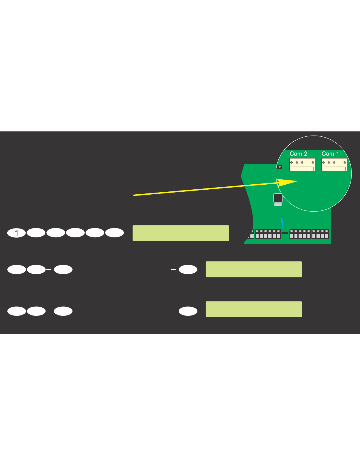
2) Texecom 412/816/832 Com Port Setup
To set up the Texecom Panel for EVENT REPORTING,
ensure the that the following settings on Panel are set.
First Check which Com Port has been
connected to the Communicator:
Enter programming menu (Default code used)
If connecting to Device Type = 000(PC-Com)Com1
if connecting to Device Type = 000(PC-Com)or Com2

Com Port Successfully
Connected & Time
Synced.
RECEIVED
.,!
GHI
ABC
DEF
JKL
MNO
PQRS
TUV
WXYZ
0
#
X
CELL PHONE
SMS
+27721234567
Set UDL Passcode:
Makes the UDL Passcode ‘1234’.
Enable Battery Monitoring:
IF REQUIRED
Enable Battery Load test &
Connection Supervision:
Exit Programming:
The setup is only done once. When the Master user is programmed, you will receive an SMS indicating
that the Serial Communication between the Panel and Communicator was successful after a powerup.
The communicator will with the network provider downloaded time.auto Sync the time
2 2
3
4
Yes
3
Menu
6
Make sure 6 is ON.
Yes
3
Make sure 2&3 are ON.
Yes
3
9 9
Master User.
Download Menu
Enter Option 0-9
Passcode1234
Download Menu
Enter Option 0-9
Programming Menu
Enter Code > ??
Programming Menu
Enter Code > ??
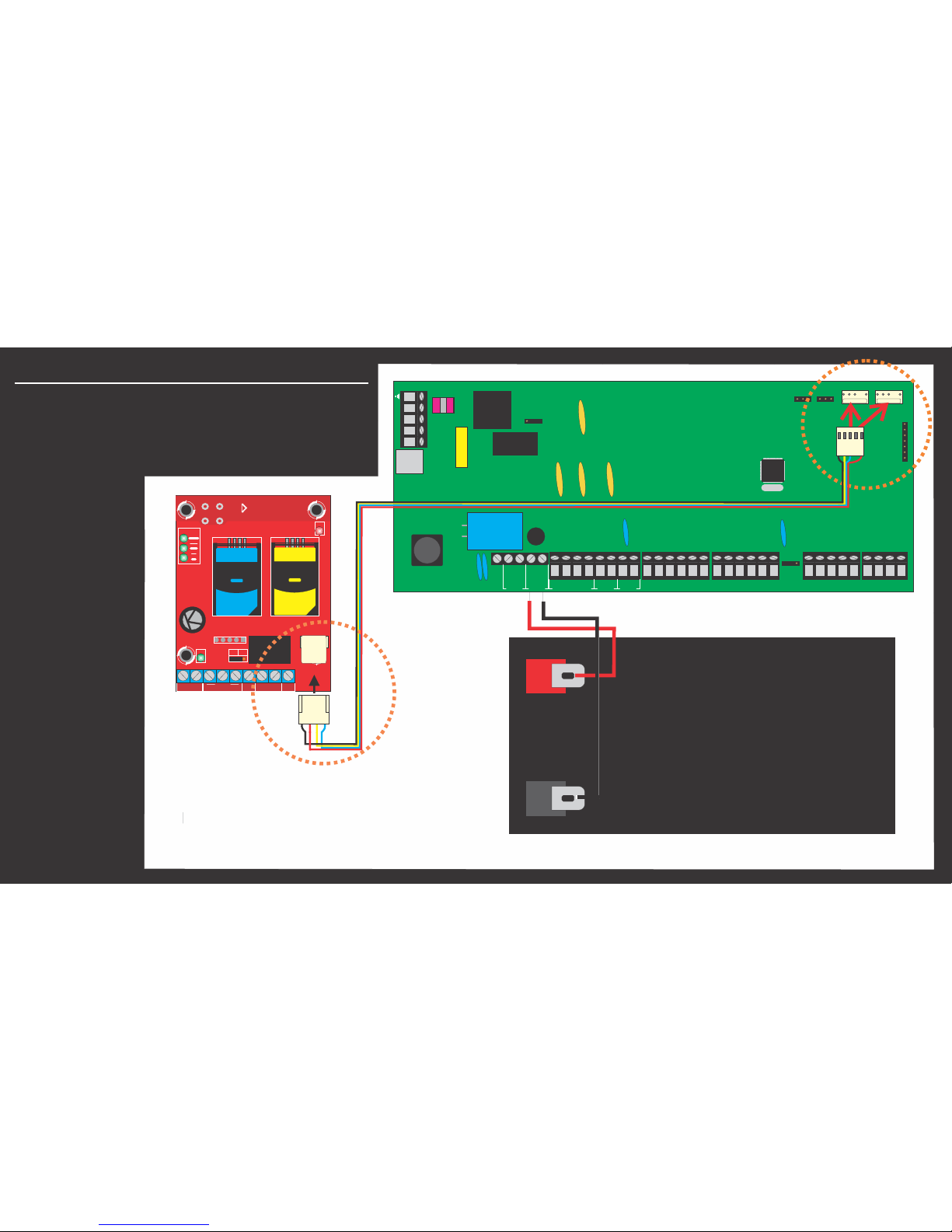
3) Communicator Connection
Connect the GSM52S SMS Communicator
with the serial cable supplied to Texecom
412/816/832 Alarm Panel as per the
following diagram
Fig 1.
TEXECOM 412/816/832 PANEL
Com 2
T R
T1 R1
W08
2200uF
Com 1
8765
4321
AUX
INP
Z8Z7Z6Z5
Z4Z3Z2
COMZ1COM
COM
COM
Aux12V
+ -
Sir/Spk
+ -
Network
+ -
T R
A.C. Batt
+
-
Fig 1
12v 7Ah Battery
The DC 12v power
directly is supplied
by the Serial Cable
from the Alarm Panel
SERIAL port on
Com1 OR Com2l.
Fox to Texecom
SERIAL/POWER Cable
INPUT
1 2 3 4
OP1 OP2
NO/C COM
POS
NEG
12V DC
PWR
PGM
NO
NC
SIM
SIM 2
SIM
SIM 1
FOX
GSM52S
SIGNAL
STAT
SERIAL
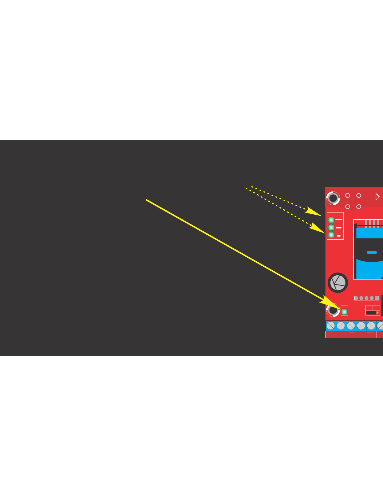
4) Communicator Start Up
With the SIM Card inserted and the Communicator DC 12V
power connected you will notice that the SIGNAL LEDs
run up and down and the flashes fast.PWR LED
This is the Normal Startup
procedure, it will continue like
this until the communicator is
registered on to the network.
You should notice that the SIGNAL LEDs STOP running
and the UPPER SIGNAL LED stays illuminated.
Every 10 seconds the signal LEDs will change to indicate
the signal level.
You are now ready to Learn the Master User.
INPUT
1 2 3 4
POS
NEG
12V DC
PWR
PGM
NO
NC
SIM
SIM 1
FOX
GSM52S
SIGNAL

5 mportant Notes for SMS Commands.) I
1. ALL Commands and custom Partition Phrases start with a ‘.’(Full stop)MUST
2. There Must be between the initial ‘.’(Full stop) and the command.NO SPACE
3. There Must be only a between a command and data.SINGLE SPACE
4. Commands are .CASE-SENSITIVE
5. Only a SINGLE Partition Phrase with per SMS is valid.ON/OFF/STAY
6. Please do not Include the words ‘ ’, ’ ’, ’ ’ or ‘ ’ in a CustomON OFF RESET STAY
Partition profile phrase.
7. Multiple setup SMS and Advanced SMS Command options are available to
execute various actions and settings. Please refer to the
‘SMS52S_AIR_TEXE_Command_Listxxxxx.pdf’ file for the latest commands.

6 Master User Setup)
The Communicator must have a valid Master User learnt in memory that allows
access to programming. The Communicator uses this Cell phone Number to validate
setup programming commands. NB: Enable SMS Delivery Reports to see that the commands
deliver to the Communicator.
From the Cell number you wish to use as the Master User, SMS the
Following:
From Master user SMS:
.M1#
To the Cell Number of
the SIM you inserted
into the Communicator.
Master User
added.
RECEIVED
.M1#
SENT
.,!
GHI
ABC
DEF
JKL
MNO
PQRS
TUV
WXYZ
0
#
X
CELL PHONE
SMS
+27721234567
This Command will add the number
of the sender as the andMaster User
will reply with an SMS confirming the
action.

7 Add System User Numbers)
The GSM52S Serial Communicator can store up to 50 Cell phone numbers.
The stored numbers will receive SMS Messages for valid events on the serial port as well as input
activations. .if the wants to receive activations, the number must also be added hereMaster User
Please note, all numbers must be entered in INTERNATIONAL FORMAT.
ie. +27xxxxxxxxx. For South African subscribers.
To add the Number 072 123 4567 which
is a South African Subscriber,
From Master User SMS:
.A +27721234567#
The newly added user is now ready to receive SMS
events from the Communicator, Activate Outputs and
Send Panel Commands.
Multiple Users may be added in one SMS by replacing
the consecutive number command with .A *A
USER Number
Successfully added:
+27721234567.
RECEIVED
.A +27721234567#
SENT
.,!
GHI
ABC
DEF
JKL
MNO
PQRS
TUV
WXYZ
0
#
X
MASTER CELL PHONE
SMS
+27xxxxxxxxx
Your Number was
added at GSM52S.
SMS Communicator.
RECEIVED
.,!
GHI
ABC
DEF
JKL
MNO
PQRS
TUV
WXYZ
0
#
X
USER CELL PHONE
SMS
+27xxxxxxxxx
Master User.
Newly Added User.

8 and Alarm ) ARM/DISARM RESET Panel
The Communicator can be used to Arm, Disarm, Stay Arm or Reset the Panel. A standard
command phrase, ‘ ’ can be used that will apply to ALL available Partitions(ie 1-4).System
Note: Up to 8 Custom Phrases can also be added. Section 10 explains how.
To ARM( ) the alarm Panel: To the alarm Panel:ON RESET
From any user SMS: From any user SMS:
.System ON# .System RESET#
OFF STAY To Disarm( ) the alarm Panel: To Arm the alarm Panel:
From any user SMS: From any user SMS:
.System OFF# .System STAY#.

Multiple Commands can also be issued after ‘ ’. The following are valid commands.System
After an alarm you might need to
remotely and then re-arm RESET
the system in mode:STAY
From any valid User SMS:
.System RESET STAY#
Arm the alarm in STAY mode.
From any valid User SMS:
.System RESET ON#
Arm all Available Partitions.
1234 Exit Started 00
1234 Remote Armed
RECEIVED
.System RESET ON#
SENT
.,!
GHI
ABC
DEF
JKL
MNO
PQRS
TUV
WXYZ
0
#
X
CELL PHONE
SMS
+27721234567

9) Bypass Panel Zones
Zones on the panel can also be Bypassed using the ‘ ’ command. Multiple zones can be .Bypass
bypassed using a single SMS. The success or failure of the zone bypass command will be indicated
via return SMS. A ‘,’(comma) must be used to separate zones to be bypassed. The zone bypass will
only be active for a single arming event.
To Bypass Zone 4:
From any valid User SMS:
.Bypass 4#
To Bypass Zones 3,6 & 7:
From any valid User SMS:
.Bypass 3,6,7#
1... Inter. 04 Byps
RECEIVED
.Bypass 4#
SENT
.,!
GHI
ABC
DEF
JKL
MNO
PQRS
TUV
WXYZ
0
#
X
CELL PHONE
SMS
+27721234567
1... Follow 03 Byps
.2.. Inter. 06 Byps
.2.. Inter. 07 Byps
RECEIVED
.Bypass 3,6,7#
SENT
.,!
GHI
ABC
DEF
JKL
MNO
PQRS
TUV
WXYZ
0
#
X
CELL PHONE
SMS
+27721234567
1... @@@@@@@
@@@@@@@@
RECEIVED
.Bypass 10#
SENT
.,!
GHI
ABC
DEF
JKL
MNO
PQRS
TUV
WXYZ
0
#
X
CELL PHONE
SMS
+27721234567
Zone 4 Successfully Bypassed
Zones 3,7 &7 Successfully Bypassed
Zone 10 does not exist on panel.

10) Set up Partition Profiles
Partition Profiles with Custom Phrases can be set up to ARM/DISARM/RESET specific Partitions,
using the .PR1 to .PR8 Commands. Up to 8 Profiles can be learned.
Please NOTE: the Phrases may NOT contain ‘*’(star) or ‘#’(hash) characters and
may NOT be longer that 14 characters.
Add Partition Profile1 called HOUSE
for activating Partition 1 only:
From Master user SMS:
.PR1 ‘HOUSE’ 1#
This will create a profile that ARMs/
DISARMs/RESETs Partition 1.
Now from any valid user SMS:
.HOUSE ON#
This will ARM Partition 1.
Profile Successfully
Learned: HOUSE.
RECEIVED
.PR1 ‘HOUSE’ 1#
SENT
.,!
GHI
ABC
DEF
JKL
MNO
PQRS
TUV
WXYZ
0
#
X
CELL PHONE
SMS
+27721234567
1... Exit Started 00
1... Remote Armed
RECEIVED
.HOUSE ON#
SENT
.,!
GHI
ABC
DEF
JKL
MNO
PQRS
TUV
WXYZ
0
#
X
CELL PHONE
SMS
+27721234567
User Activates Alarm Panel via SMS
Master User Creates Profile1

Please note that only a single space is used a separator after the Phrase and the partition
numbers follow directly after each other.
Add Partition Profile2 called Perimeter
for activating Partitions 2&3:
From Master user SMS:
.PR2 ‘Perimeter’ 23#
This will create a profile that ARMs/
DISARMs/RESETs Partitions 2&3.
Now from any valid user SMS:
.Perimeter ON#
This will ARM Partitions 2&3.
Profile Successfully
Learned: Perimeter.
RECEIVED
.PR2 ‘Perimeter’
23#
SENT
.,!
GHI
ABC
DEF
JKL
MNO
PQRS
TUV
WXYZ
0
#
X
CELL PHONE
SMS
+27721234567
.23. Exit Started 00
.23. Remote Armed
RECEIVED
.Perimeter ON#
SENT
.,!
GHI
ABC
DEF
JKL
MNO
PQRS
TUV
WXYZ
0
#
X
CELL PHONE
SMS
+27721234567
User Activates Alarm Panel via SMS
Master user Creates Profile2

IMPORTANT:
The words ‘ON’, ’OFF’, ’RESET’ or ‘STAY’ must NOT be used in a Partition phrase.
Add Partition Profile3 called Panel
for activating all available Partitions.
(Leave out Partition Numbers)
From Master user SMS:
.PR3 ‘Panel’#
This will create a profile that ARMs/
DISARMs/RESETs ALL Partitions.
Now from any valid userSMS:
.Panel ON#
This will ARM ALL Partitions.
1234 Exit Started 00
1234 Remote Armed
RECEIVED
.Panel ON#
SENT
.,!
GHI
ABC
DEF
JKL
MNO
PQRS
TUV
WXYZ
0
#
X
CELL PHONE
SMS
+27721234567
User Activates Alarm Panel via SMS
Master User Creates Profile3
CELL PHONE
SMS
+27721234567
SENT
.PR3 ‘Panel’#
RECEIVED
.,!
GHI
ABC
DEF
JKL
MNO
PQRS
TUV
WXYZ
0
#
X
Profile Successfully
Learned: Panel.

11) Request Panel or Communicator Status
The users can request the INPUT, voltage, signal strength and SIM slot used or airtime on SIM1
of the Communicator.
To request the Status( ealth) H
of the Texecom anelP
From any User SMS:
.HP#
NOTE: After airtime setup
is completed.
To request the time on AIR
the Communicator SIM1
Master or Admin User SMS:
.AIR#
RECEIVED
.H#
SENT
.,!
GHI
ABC
DEF
JKL
MNO
PQRS
TUV
WXYZ
0
#
X
CELL PHONE
SMS
+27721234567
Status Report-
Batt:13.8v
Sig:57%
IP1:H
IP2:L
IP3:H
IP4:L
OP1:L
OP2:L
AC Pwr: ON*
SIM1
V:xxxxxT
06/08/2017
19:38
RECEIVED
.AIR#
SENT
.,!
GHI
ABC
DEF
JKL
MNO
PQRS
TUV
WXYZ
0
#
X
CELL PHONE
SMS
+27721234567
Your balance is
R230.00.
08/11/2016
10:35

12) Troubleshooting
Use The following Table to identify any fault
conditions you might encounter with the
Communicator power supply.
Signal LEDs
According to RSSI*
Signal Level
According to RSSI*
Signal Level
According to RSSI*
Signal Level
All OFF
CONDITION
PWR LED
Battery Good-
AC OFF
Steady(0.5s ON,
0.5s OFF)
Battery Good-
AC ON
Quick(0.25s ON,
0.75s OFF)
Battery DC Over Voltage
(V>15.0v DC)
Solid(Peranently ON)
Battery Critical Shutdown
(V<8.5v DC)
OFF
SMS Sending
Slow(1.75s ON,
0.25s OFF)
Signal strength :
Low+Mid+High = 75%-100%
Low+Mid = 45%-75%
Low = 25%-45%
Low Flashing = 0%-25%
INPUT
1 2 3 4
OP1 OP2
NO/C COM
POS
NEG
12V DC
PWR
PGM
NO
NC
SIM
SIM 2
SIM
SIM 1
FOX
GSM52S
SIGNAL
STAT
SERIAL
Signal
LEDs
High
Mid
Low
PWR
LED

ERRORS
Signal LEDs
No SIM Inserted or
SIM not RECOGNIZED
LOW ONSignal LED ,
others off
SMS Sending Error/
No Air time**
MID ON Signal LED ,
others off
Signal Critically
Low**
Startup/Restart/
SIM Switching**
LOW FLASHING Signal LED ,
others off
Signal LEDs Pulsing
and UP DOWN
No Master User
In Memory**
HIGH ON Signal LED ,
others off
Use this table to identify system ERRORS. The
error conditions are indicated by the SIGNAL LEDs
when the PWR LED is flashing fast
NOTE: If on startup the Low Signal LED Flashes fast,
in stead of the Signal LEDs pulsing Up and Down,
the Battery Voltage is LOW.
INPUT
1 2 3 4
OP1 OP2
NO/C COM
POS
NEG
12V DC
PWR
PGM
NO
NC
SIM
SIM 2
SIM
SIM 1
FOX
GSM52S
SIGNAL
STAT
SERIAL
Signal
LEDs
High
Mid
Low
PWR
LED
 Loading...