

Page 1

Statement:
This manual is the intellectual property of Foxconn, Inc. Although the
information in this manual may be changed or modified at any time,
Foxconn does not obligate itself to inform the user of these changes.
Trademark:
All trademarks are the property of their respective owners.
Version:
User Manual V1.0 for X38A motherboard.
P/N: 3A220MJ00-000-G
Symbol description:
Note: refers to important information that can help you to use motherboard
better.
Attention: indicates that it may damage hardware or cause data loss,
and tells you how to avoid such problems.
Warning: means that a potential risk of property damage or physical
injury exists.
More information:
If you want more information about our products, please visit Foxconn’s
website: http://www.foxconnchannel.com
WEEE: The use of the symbol indicates that this product may not be
treated as household waste. By ensuring this product is disposed of
correctly, you will help prevent potential negative consequences for the
environment and human health, which could otherwise be caused by
inappropriate waste handling of this product. For more detailed informa-
tion about recycling of this product, please contact your local city office,
your household waste disposal service or the shop where you pur-
chased the product.
Page 2

Declaration of conformity
HON HAI PRECISION INDUSTRY COMPANY LTD
66 , CHUNG SHAN RD., TU-CHENG INDUSTRIAL DISTRICT,
TAIPEI HSIEN, TAIWAN, R.O.C.
declares that the product
Motherboard
X38A
is in conformity with
(reference to the specification under which conformity is declared in
accordance with 89/336 EEC-EMC Directive)
þ EN 55022: 1998/A2: 2003Limits and methods of measurements of radio disturbance
characteristics of information technology equipment
þ EN 61000-3-2/:2000 Electromagnetic compatibility (EMC)
Part 3: Limits
Section 2: Limits for harmonic current emissions
(equipment input current <= 16A per phase)
þ EN 61000-3-3/A1:2001 Electromagnetic compatibility (EMC)
Part 3: Limits
Section 2: Limits of voltage fluctuations and flicker in low-voltage
supply systems for equipment with rated current <= 16A
þ EN 55024/A2:2003 Information technology equipment-Immunity characteristics limits
and methods of measurement
Signature : Place / Date : TAIPEI/2007
Printed Name : James Liang Position/ Title : Assistant President
Page 3

Declaration of conformity
Trade Name: FOXCONN
Model Name: X38A
Responsible Party: PCE Industry Inc.
Address: 458 E. Lambert Rd.
Fullerton, CA 92835
Telephone: 714-738-8868
Facsimile: 714-738-8838
Equipment Classification: FCC Class B Subassembly
Type of Product: Motherboard
Manufacturer: HON HAI PRECISION INDUSTRY
COMPANY LTD
Address: 66 , CHUNG SHAN RD., TU-CHENG
INDUSTRIAL DISTRICT, TAIPEI HSIEN,
TAIWAN, R.O.C.
Supplementary Information:
This device complies with Part 15 of the FCC Rules. Operation is subject to the follow-
ing two conditions : (1) this device may not cause harmful interference, and (2) this
device must accept any interference received, including interference that may cause
undesired operation.
Tested to comply with FCC standards.
Signature : Date : 2007
Page 4

Table of Contents
Chapter
Product Introduction
Package List...........................................................................................2
Main Features........................................................................................3
Special Features....................................................................................5
Layout......................................................................................................7
Rear I/O Ports.........................................................................................8
Chapter
CPU.......................................................................................................10
Memory..................................................................................................12
Expansion Slots...................................................................................13
Connectors...........................................................................................15
Jumpers...............................................................................................21
Onboard Buttons..................................................................................22
Onboard LED Debug...........................................................................22
Chapter
Enter BIOS Setup.................................................................................24
Main menu............................................................................................24
Standard BIOS Features.....................................................................26
Advanced BIOS Features....................................................................26
Advanced Chipset Features...............................................................32
PCI/PNP Resource Management......................................................35
Boot Configuration Features..............................................................36
Power Management Features............................................................38
BIOS Security Features.......................................................................42
Fox Central Control Unit......................................................................43
Hardware Health Configure................................................................46
Load Optimal Defaults........................................................................47
Load Failsafe Defaults........................................................................47
Discard Changes................................................................................47
Save Changes and Exit.......................................................................47
Discard Changes and Exit..................................................................48
1
1
Installation Instructions
2
2
BIOS Description
3
3
Page 5

Table of Contents
Chapter
FOX ONE...............................................................................................50
FOX LiveUpdate...................................................................................57
FOX LOGO............................................................................................64
FOX DMI................................................................................................65
Chapter
RAID Configuration
Introduction...........................................................................................67
Installing Serial ATA Hard Disks.........................................................68
BIOS Configuration..............................................................................68
RAID BIOS Configuration....................................................................68
Creating a RAID Driver Floppy Disk...................................................74
Install OS on HDD with RAID set.......................................................74
44
Directions for Bundled Software
5
5
Appendix
CrossFireTM Technology......................................................................76
Page 6
Attention:
1.Attach the CPU and heatsink using silica gel to ensure full contact.
2.It is suggested to select high-quality, certified fans in order to avoid
damage to the motherboard and CPU due high temperatures.
3.Never turn on the machine if the CPU fan is not properly installed.
4.Ensure that the DC power supply is turned off before inserting or
removing expansion cards or other peripherals, especially when
you insert or remove a memory module. Failure to switch off the DC
power supply may result in serious damage to your system or
memory module.
Attention:
We cannot guarantee that your system will operate normally while
overclock. Normal operation depends on the overclock capacity of
your device.
Attention:
Since BIOS programs are upgraded from time to time, the BIOS
description in this manual is just for reference. We do not guarantee
that the content of this manual will remain consistent with the actual
BIOS version at any given time in the future.
Attention:
The pictures of objects used in this manual are just for your reference.
Please refer to the physical motherboard.
Attention:
Please visit the Foxconn English website (http://www.foxconnchannel.
com) to download the latest BIOS file and drivers for this motherboard.
Page 7
Chapter
1
1
X38A is the first product in a new series called Digital Life.
Digital Life motherboards combine high-performance
computing, wider options for accessing and managing other
devices, and technologies which enable easy access to a world
of digital entertainment via your PC.
Foxconn Digital Life products are engineered to maximize the
computing power at your fingertips, whilst providing a wider
range of connectivity options which enable more flexibility
from your PC for multimedia and entertainment applications.
The Digital Life series of products allow you to do more with
your PC.
This chapter includes the following information:
v Package List
v Main Features
v Special Features
v Layout
v Rear I/O Ports
Page 8
Chapter 1 Product Introduction
Package List:
Check your motherboard package for the following items:
Motherboard Foxconn X38A motherboard
I/O modules 1 X USB 2.0 x 2 ports and 1 x 1394a module
Cables 6 X SATA Power and SATA Signal cables
1 X Ultra DMA 133/100/66 and Floppy Disk Drive
cable
Accessory I/O Shield
1 X Foxconn Optional Fan
Application CD Foxconn motherboard support CD
Documentation User Manual
Easy Guide
Note:
If any of the above item is damaged or missing, please contact
your retailer.
2
Page 9
Main Features
Chapter 1 Product Introduction
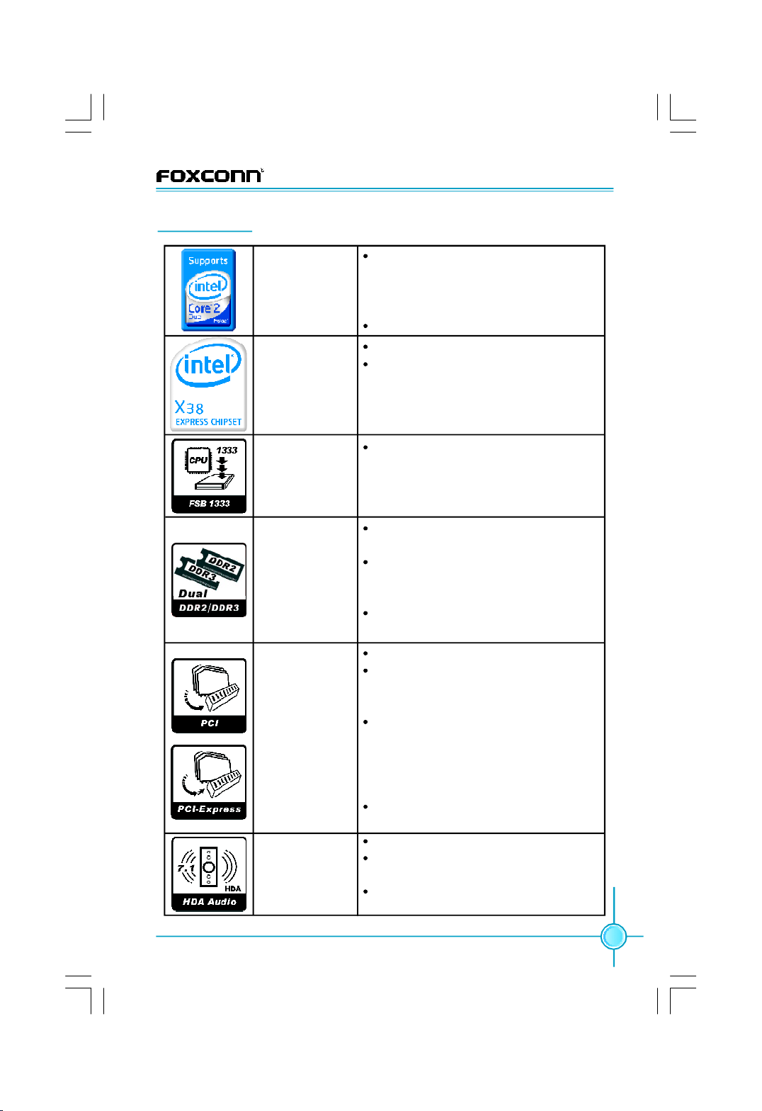
CPU
Supports Intel® CoreTM 2 Quad, Core
Extreme, CoreTM 2 Duo, Pentium® DualCore E2xxx processors in an LGA 775
package
Supports upcoming 45nm processors
Chipset
Northbridge: Intel® X38
Southbridge: Intel® ICH9R
Front Side Bus
Supports Front Side Bus(FSB) at
1333MHz / 1066MHz / 800MHz
Memory
Dual-Channel DDR2 and DDR3 memory
architecture
4 x 240-pin, 1.8V, DDR2 DIMM slots
support up to 8GB; 2 x 240-pin, 1.5V,
DDR3 DIMM slots support up to 4GB
DDR2 up to 1066 (O.C) MHz / 800MHz;
DDR3 up to 1333MHz
Expansion
Slots
2 X PCI Slots
2 X PCI Express x1 slots and support
250MB/s (500MB/s concurrent) bandwidth
2 x PCI Express x16 Graphics slots and
support 8GB/s (16GB/s concurrent)
bandwidth, 1 x PCI Express x16
Graphics slot (Black) and supports
1GB/s (2GB/s concurrent) bandwidth.
Low power consumption and power
management features
High
Definition
Audio
Supports S/PDIF output
Supports Jack-Sensing and Jackretasking function
Compliant with Intel® HD Audio specification
(continued on the next page)
TM
2
3
Page 10
Chapter 1 Product Introduction
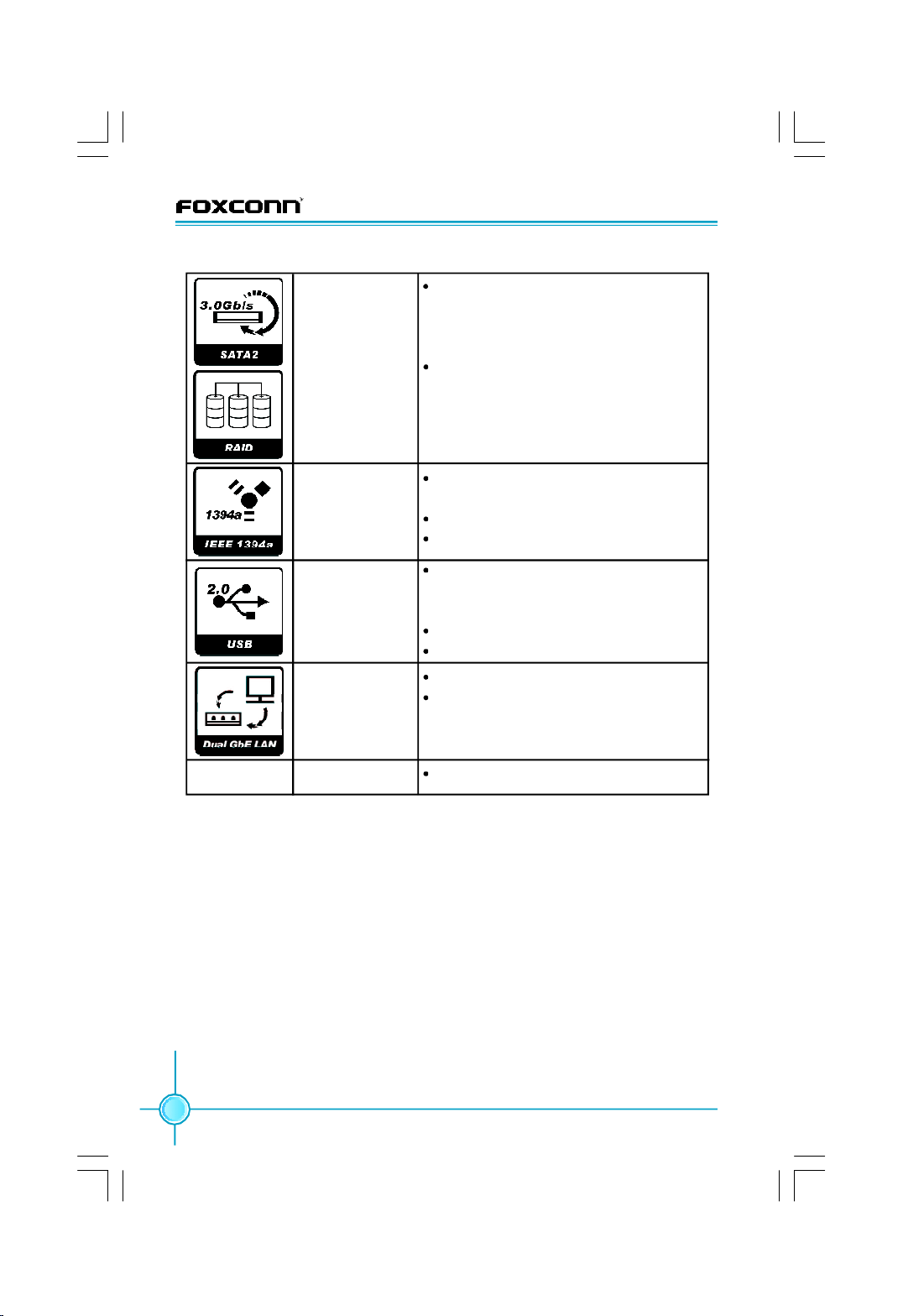
Storage
IEEE 1394a
USB 2.0 Ports
Gigabit LAN
Size
Supported by JMicron® JMB363
-2 x Ultra DMA 133/100/66 devices
-2 x eSATA devices
-RAID 0, 1, JBOD configuration
Supported by ICH9R
-6 x SATA devices
-RAID 0, RAID 1, RAID 5, RAID 0+1
configuration with Intel® Matrix Storage
Technology
2 x IEEE 1394a(one rear panel port, the
other onboard connector )
400Mb/s data transfer rate
Supports hot plug
8 x USB 2.0 Ports (4 rear panel ports, 2
x onboard USB headers providing 4 x
extra ports)
480Mb/s data transfer rate
Supports hot plug
Two LAN interfaces built-in onboard
Supports 10/100/1000Mb/s Ethernet
ATX form factor of 305mm x 244mm
·Specifications are subject to change without notice
4
Page 11
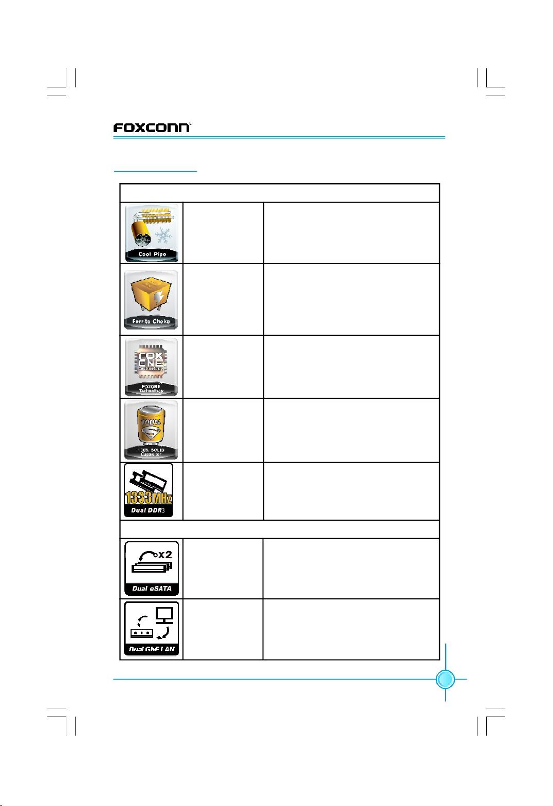
Special Features
ENGINEERED FOR PERFORMANCE COMPUTING
Cool Pipe
Chapter 1 Product Introduction
Removes heat from the critical VRM,
North and South Bridge areas, increas-
ing overclocking potential.
Ferrite Choke
FOX ONE
100% SOLID
Capacitor
DDR3 1333MHz
Support
Ferrite Choke design holds energy at a
higher frequency than traditional iron
cores, resulting in less power loss and
more stability and performance capability
for your system.
Onboard chipset and Windows-based
control panel for easy overclocking and
system monitoring capability.
100% SOLID Capacitor design for
improved reliability and performance.
Native DDR3 1333MHz support unlocks
more performance when overclocking
CPU with memory.
CONNECTIVITY FOR THE DIGITAL WORLD
Dual eSATA
Dual eSATA ports located on the rear I/
O enable connection of 2 external
devices via high-speed eSATA.
Dual Gigabit LAN
(continued on the next page)
Do more online with Dual Gigabit LAN;
connect to 2 independent networks
without speed loss.
5
Page 12
Chapter 1 Product Introduction
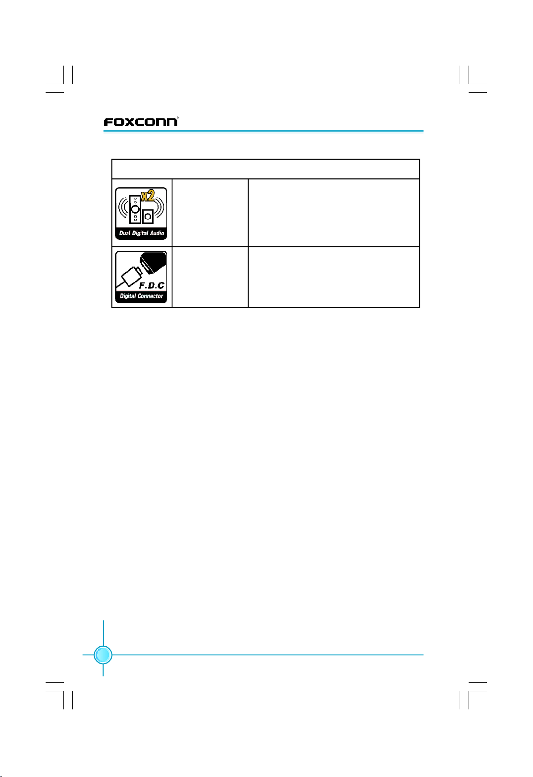
ENABLING DIGITAL ENTERTAINMENT
Dual Digital Audio
Foxconn Digital
Connector
Dual Digital Audio enables you to
configure up to 8 channels of audio
between the two outputs, so you can
isolate different sound sources on your
PC.
Enables connection to Foxconn digital
entertainment and communications
products, opening up a world of digital
possibilities.
6
Page 13
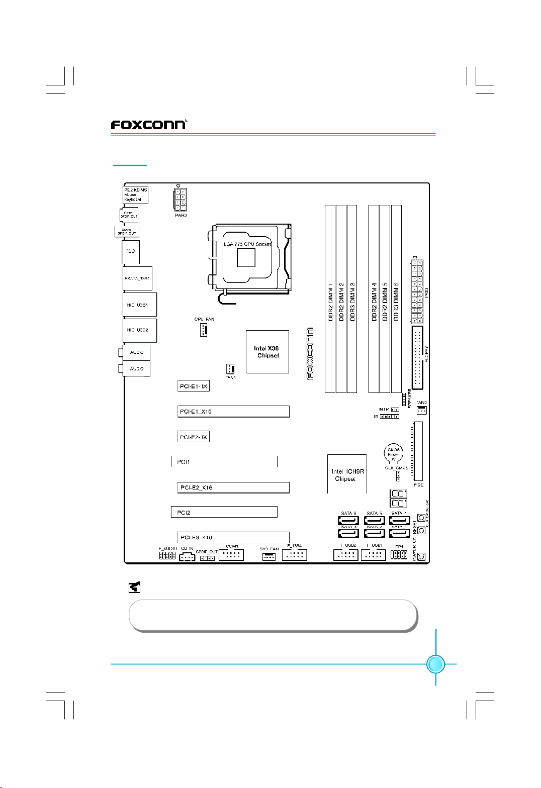
Layout
Chapter 1 Product Introduction
Note:
The above motherboard layout is provided for reference only,
please refer to the physical motherboard.
7
Page 14
Chapter 1 Product Introduction
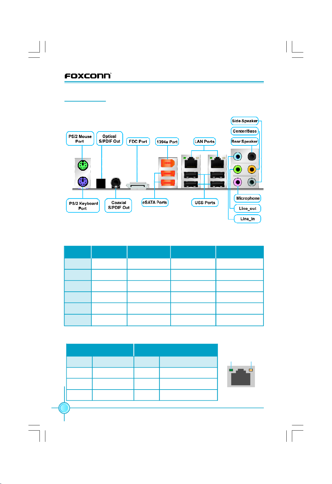
Rear I/O Ports
This motherboard provides the ports as below:
加个警告:
Line in, Line out, Microphone, Rear, Center/Bass and Side Jacks
Port 2-channel 4-channel 6-channel 8-channel
Blue Line_in Line_in Line_in Line_in
Green Line_out Front Speaker Front Speaker Front Speaker
Pink Microphone Microphone Microphone Microphone
Orange - - Center/Bass Center/Bass
Black - Rear Speaker Rear Speaker Rear Speaker
Grey - - - Side Speaker
LAN Port
Left : Link/Active LED Right: Speed LED
Status Description Status Description
Off No Link Off 10 Mb/s Connection
Green Linked Green 100 Mb/s Connection
Blinking Data Activity Orange 1 Gb/s Connection
Link/Active
LED
LAN Port
8
Speed
LED
Page 15

Chapter 1 Product Introduction
Chapter
This chapter introduces the hardware installation process, in-
cluding the installation of the CPU, memory, power supply, slots,
and pin headers, and the mounting of jumpers. Caution
should be exercised during the installation of these modules.
Please refer to the motherboard layout prior to any installation
and read the contents in this chapter carefully.
This chapter includes the following information:
v Onboard LED Debug
2
2
v CPU
v Memory
v Expansion Slots
v Connectors
v Jumpers
v Onboard Buttons
9
Page 16
CPU
Chapter 2 Installation Instructions
This motherboard supports Intel® CoreTM 2 Quad, Core
TM
2 Extreme, CoreTM 2
Duo, Pentium® Dual-Core E2xxx processors in an LGA775 package with Front
Side Bus (FSB) of 1333/1066/800MHz.
For the detailed CPU support list on this motherboard, please visit the
website: http://www.foxconnchannel.com
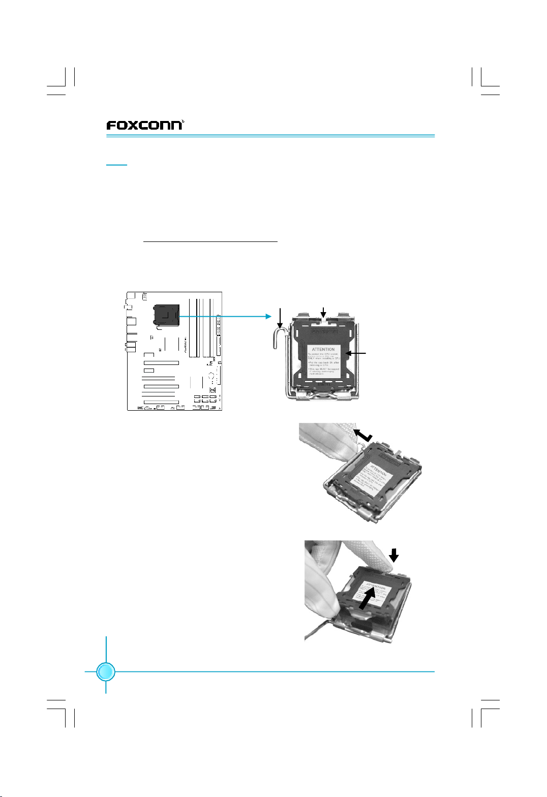
Installation of CPU
Below is the CPU socket illustration. Follow these procedures to install a CPU.
Load lever
Load plate
Protective cover
CPU Socket 775
1. Use thumb and forefinger to hold the
hook of the load lever and pull the
lever down and away from socket to
unlock it. Lift the load lever.
2. Push down the rear tab with your forefin-
ger to bring the front end of the load plate
up slightly. Open the load plate with
thumb. Be careful not to touch the
contacts.
10
Page 17
Chapter 2 Installation Instructions
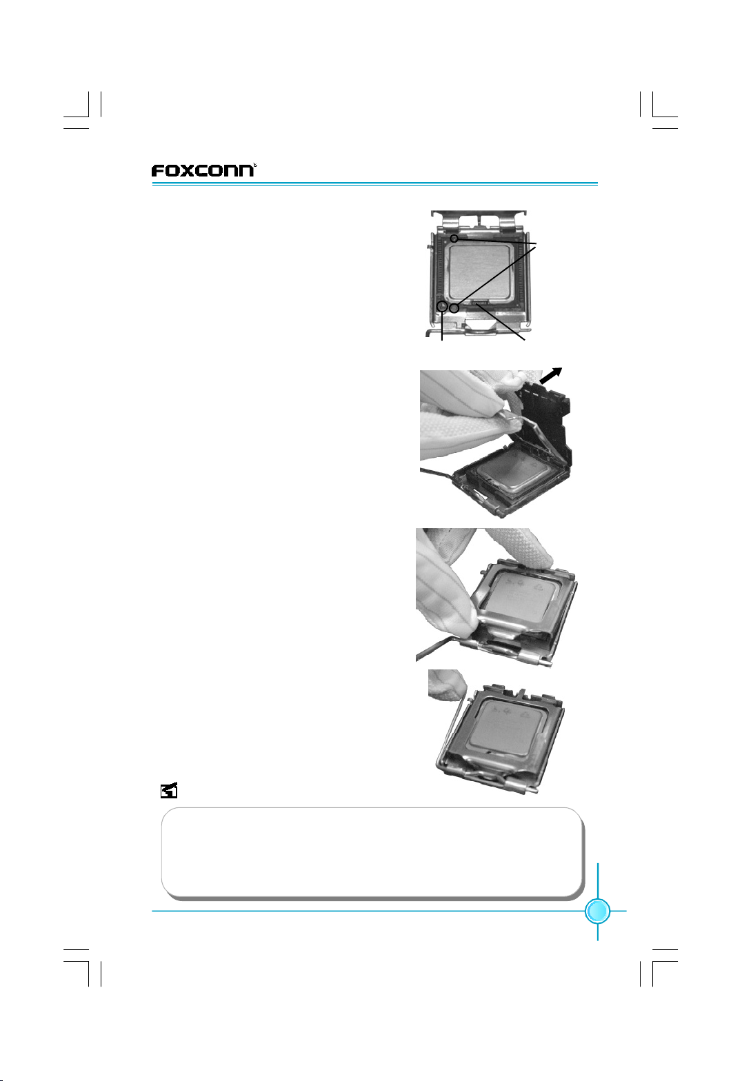
3. Hold CPU with thumb and forefinger.
Ensure fingers align to socket cutouts.
Match the CPU triangle marker to Pin 1
position as shown below. The alignment key also provides the orientation
directed function. Lower the CPU
straight down without tilting or sliding
the CPU in the socket.
4. After installing the CPU, remove the pro
tective cover from load plate. The protective cover is used to protect the contacts of
the socket. Do not discard the protective
cover. Always replace the socket cover if
the CPU is removed from the socket.
Alignment
Key
Socket CutoutsPin 1 position
5. Close the load plate, and slightly push
down the tongue side.
6. Lower the lever and lock it to the load
plate, then the CPU is locked completely.
Note :
Excessive temperatures will severely damage the CPU and system.
Therefore you should install the CPU cooling fan and make sure that it
works normally at all times in order to prevent overheating and damage
to the CPU. Please refer to your CPU fan user guide for correct
installation.
11
Page 18
Chapter 2 Installation Instructions
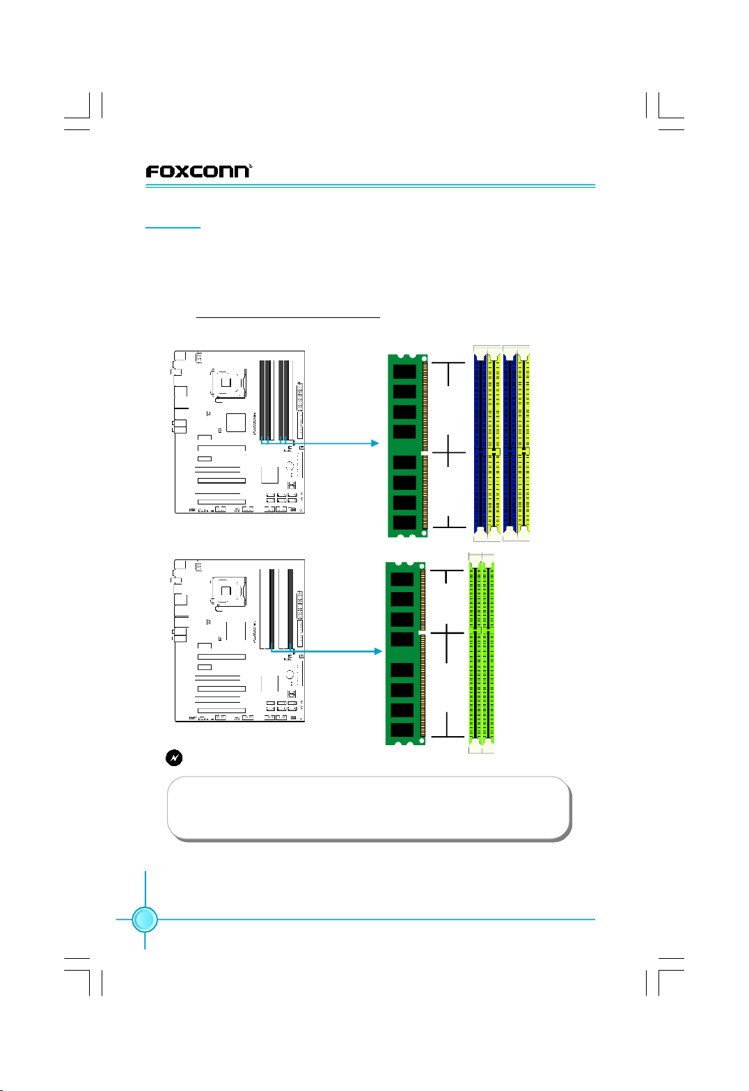
Memory
This motherboard includes four 240-pin slots with 1.8V for DDR2 and two 240pin slots with 1.5V for DDR3. You must install at least one memory bank to
ensure normal operation.
For the detailed memory support list on this motherboard, please visit the
website: http://www.foxconnchannel.com
The figures illustrate the location of the DDR2 and DDR3 DIMM slots:
112-Pin 128-P in
240-pin DDR2 DIMM Slots
96-Pin144-Pin
240-pin DDR3 DIMM Slots
Warning:
Do not install DDR2 and DDR3 memory modules simultaneously
on this motherboard, doing so may result in damage to the
motherboard and your system.
Installation a DIMM
1.There is one gap near the center of the DIMM slot, and the memory
module can be fixed in one direction only.
12
Page 19
Chapter 2 Installation Instructions
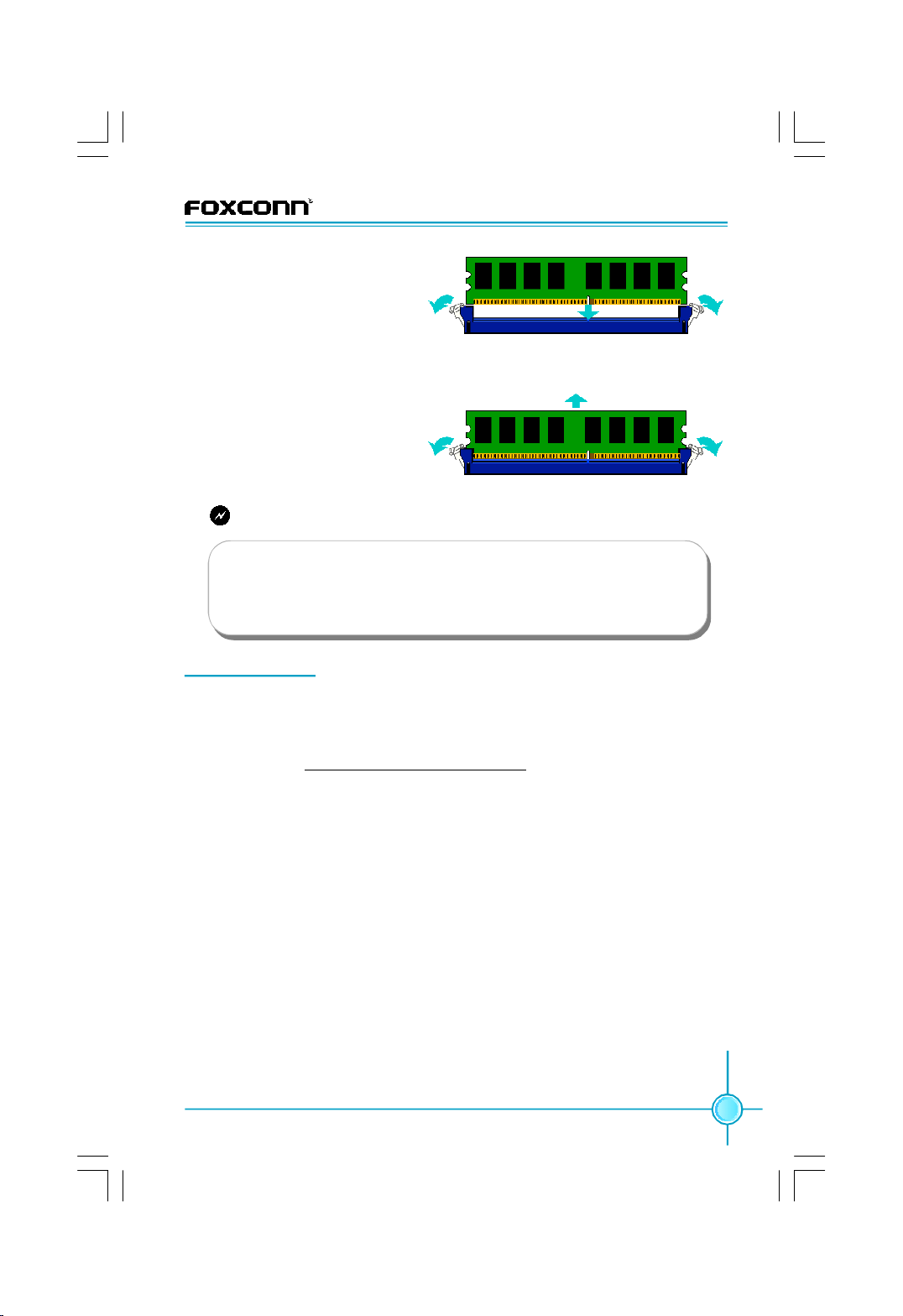
2.Align the memory module to
the DIMM slot, and insert the
module vertically into the DIMM
slot.
3.The plastic clips at both sides of the DIMM slot will lock automatically.
Removing a DIMM
1.Unlock the DIMM slot by pressing the module clips outward.
2.Remove the Memory bank
from the slot.
Warning:
Be sure to unplug the AC power supply before adding or removing
expansion cards or other system peripherals, especially the
memory modules, otherwise the motherboard or the system
might be seriously damaged.
Expansion Slots
This motherboard includes two 32-bit master PCI slots, two PCI Express x1
slots and three PCI Express x16 slots.
For the detailed PCI Express cards support list on this motherboard, please
visit the website: http://www.foxconnchannel.com
PCI Slots
The expansion cards can be installed in the two PCI slots. PCI slots support
cards such as a LAN card, USB card, SCSI card and other cards that comply
with PCI specifications.
PCI Express x1 Slots
This motherboard has two PCI Express x1 slots that designed to accommodate
less bandwidth-intensive cards, such as a modem or LAN card. The PCI Express x1 slot offering 250MB/s (500MB/s concurrent) of bandwidth.
PCI Express x16 Slots
This motherboard has three PCI Express x16 slots that reserved for graphics or
video cards. Two PCI Express x16 slots offering 8GB/s (16GB/s concurrent) of
bandwidth and One PCI Express x16 slot (Black) offering 1GB/s (2GB/s
concurrent) of bandwidth.
13
Page 20
Chapter 2 Installation Instructions
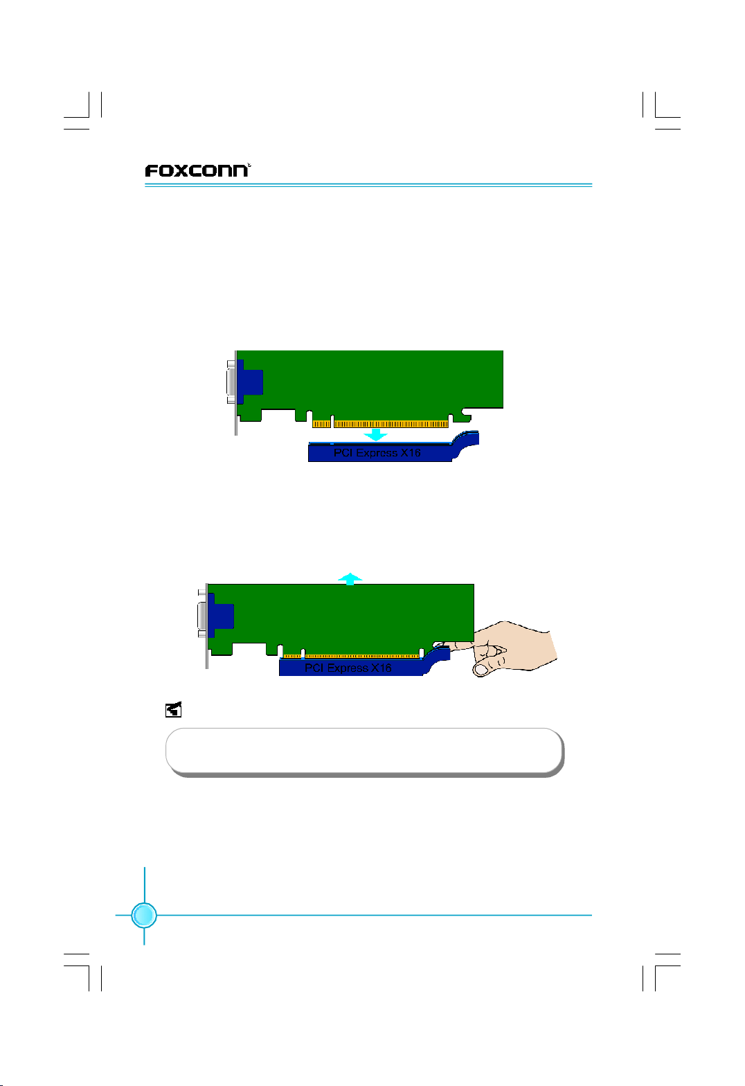
Installing an expansion card
1.Before installing the expansion card, read carefully the documentation that
comes with and make the necessary hardware settings for the card.
2.Make sure to unplug the power cord before adding any expansion cards,
Remove the bracket on the corresponding position of the rear panel.
3.Align the card with the interface of the slot and vertically press the card
down until it has been completely seated in the slot.
4.Secure the card onto the rear panel of the chassis with screws.
Uninstalling an expansion card
1.Make sure to unplug the power cord before removing the expansion card.
2.Remove the fixed screws on the real panel.
3.Press the retaining clip at one side (as show), then you can remove the
expansion card from the slot.
14
Note:
If a performance graphics card was installed into x16 PCI Express slot, 24-pin power supply was recommended.
Page 21
Chapter 2 Installation Instructions
Connectors
This motherboard includes connectors for power supply, FDD device, IDE device,
Serial ATA devices, USB devices, IR module, and others. Make sure that they
have been installed properly prior to connecting the power supply.
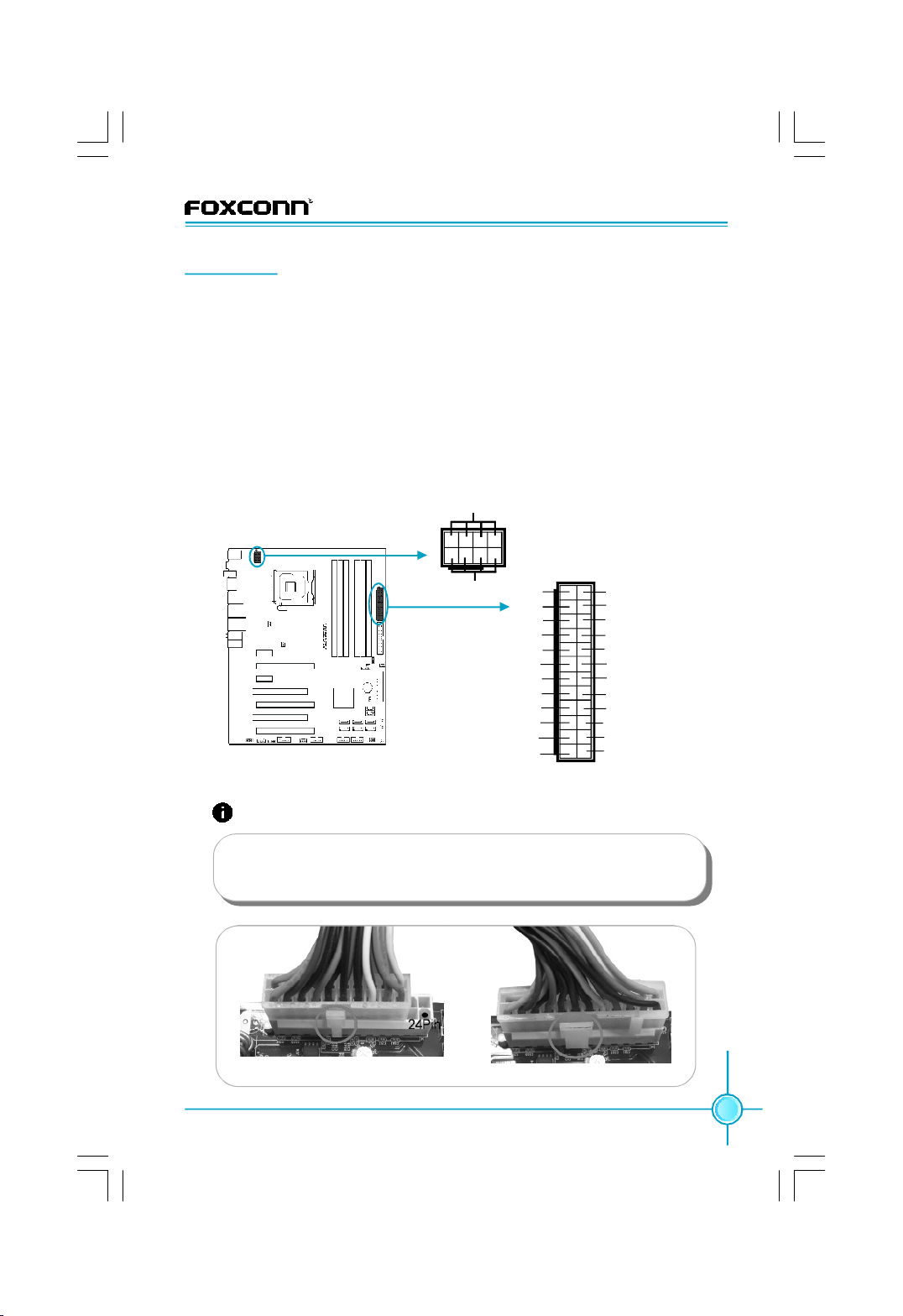
24-pin ATX power connector: PWR1
PWR1 is the ATX power supply connector. Make sure that the power supply
cable and pins are properly aligned with the connector on the motherboard.
Firmly plug the power supply cable into the connector and make sure it is secure.
8-pin ATX_12 V Power Connector: PWR2
The 8-pin ATX 12V power supply connects to PWR2 and provides power to the
CPU.
Power Connectors
GND
1
5
4
8-pin ATX_12 V
Power Connector
8
12V
+3.3V
-12V
GND
PSON
GND
GND
GND
NC
+5V
+5V
+5V
GND
24-pin ATX Power Connector
13 1
24 12
+3.3V
+3.3V
+5V_AUX
GND
+5V
GND
+5V
GND
PWROK
+12V
+12V
+3.3V
Attention:
We recommend you use 24-pin power supply. If you want to use
20-pin power supply, you need to align the ATX power connector
according to the following picture.
20-Pin Power 24-Pin Power
15
Page 22
Chapter 2 Installation Instructions
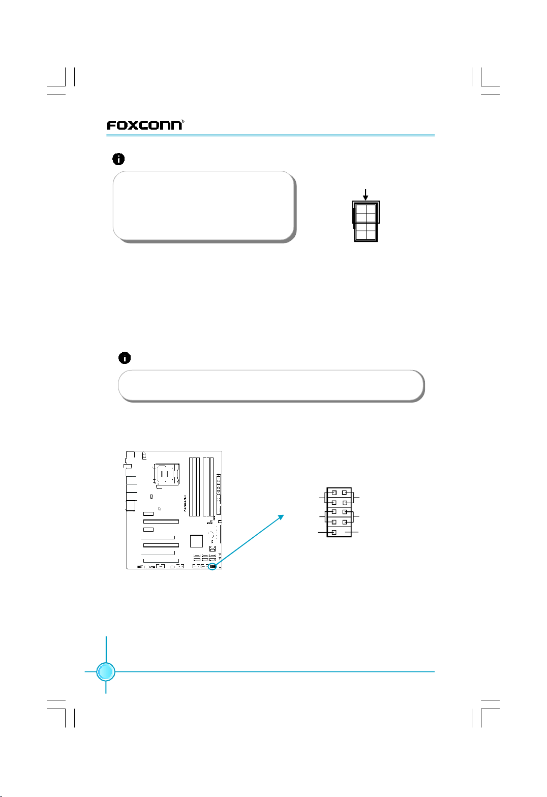
Attention:
Connect a 4-pin power
We recommend you use 8-pin ATX 12V
power supply. If you want to use 4-pin
power supply, you need to align the ATX
power connector according to the right
picture.
FDD Connector: FLOPPY
This motherboard includes a standard Floppy connector, supporting [360KB,
51/4 in], [1.2MB, 51/4in], [720KB, 31/2 in], [1.44MB, 31/2 in], [2.88 MB, 31/2 in] FDDs.
IDE Connectors: PIDE
This connector supports the provided Ultra DMA 133/100/66 IDE hard disk ribbon
cable and you can configure as a disk array through RAID controller.
Attention:
If you install two IDE devices, you must configure the second drive
as a slave device.
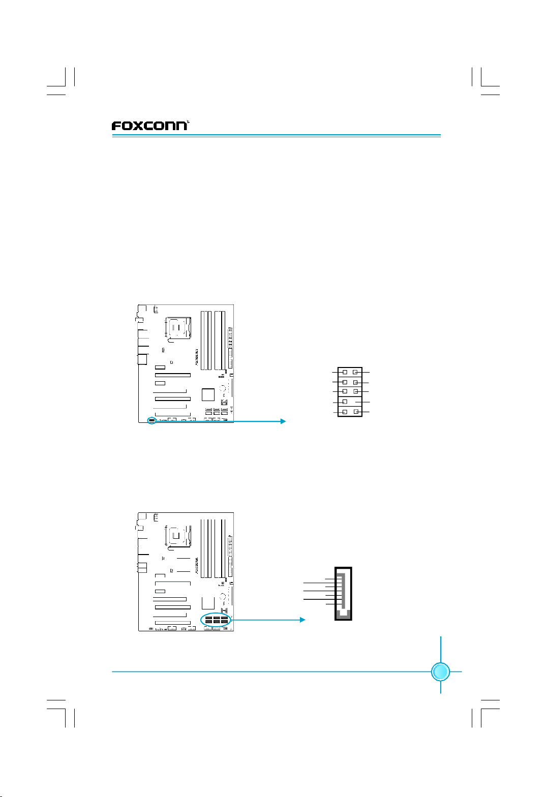
Front Panel Connector: FP1
This motherboard includes one connector for connecting the front panel switch
and LED indicators.
plug here
5
8
1
4
1 2
HD_LED
RESET
NC
+
-
+
PWR_LED
-
PWRSW
Empty
9 10
FPFP1!
Front Panel Connector
Hard Disk LED Connector (HD_LED)
The connector connects to the case’s IDE indicator LED indicating the activity
status of hard disks.
Reset Switch (RESET)
Attach the connector to the Reset switch on the front panel of the case; the
system will restart when the switch is pressed.
16
Page 23
Chapter 2 Installation Instructions
Power LED Connector (PWR_LED)
Attach the connector to the power LED on the front panel of the case. The Power
LED indicates the system’s status. When the system is in S0 status, the LED is
on; When the system is in S1 status, the LED is blink; When the system is in S3,
S4, S5 status, the LED is off.
Power Switch Connector (PWRSW)
Attach the connector to the power button of the case. Pushing this switch allows
the system to be turned on and off rather than using the power supply button.
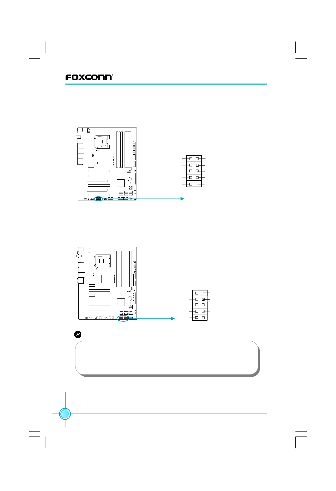
Front Audio Connector: F_AUDIO
This audio connector supports HD audio standard. Front Audio supports retasking function.
PORT1_L
PORT1_R
PORT2_R
SENSE_SEND
PORT2_L
Front Audio Connector
1 2
F_AUDIO (HD Audio)
9 10
AUD_GND
PRESENCE_J
SENSE1_RETURN
Empty
SENSE2_RETURN
Serial ATA II Connectors: SATA_1, SATA_2, SATA_3, SATA_4, SATA_5, SATA_6
The Serial ATA II connector is used to connect the Serial ATA II device to the
motherboard. These connectors support the thin Serial ATA II cables for Serial
ATA II devices. The current Serial ATA II interface allows up to 300MB/s data
transfer rate.
GND
RX+
RX-
GND
TX-
TX+
GND
SATA_1/2/3/4/5/6
Serial SATA II Connectors
1
17
Page 24
Chapter 2 Installation Instructions
Serial Port Connector: COM1
This connector is for a serial (COM) port. Connect the serial port module cable
to the connector, then install the module to a slot opening at the back of the
system chassis.
GND
RTS
1 2
SIN
DTR
DSR
CTS
RI
COM1
Empty
9
10
RLSD
SOUT
COM1 Connector
USB 2.0 Connectors: F_USB1/2
In addition to the USB ports on the rear panel, this series of motherboard also have
two 10-pin headers onboard, which may be used to connect two front panel USB
cables/brackets to provide additional four USB ports.
10 9
USB 2.0 Connectors
NC
D+
D-
VCC
F_USB 1/2
2 1
Empty
GNDGND
D+
D-
VCC
Warning:
Before installing the USB cables, please pay attention to the marker
of each individual USB cable; make sure to match them with each
USB pin headers correctly, otherwise the USB ports will not work.
Incorrect connection could also damage the motherboard.
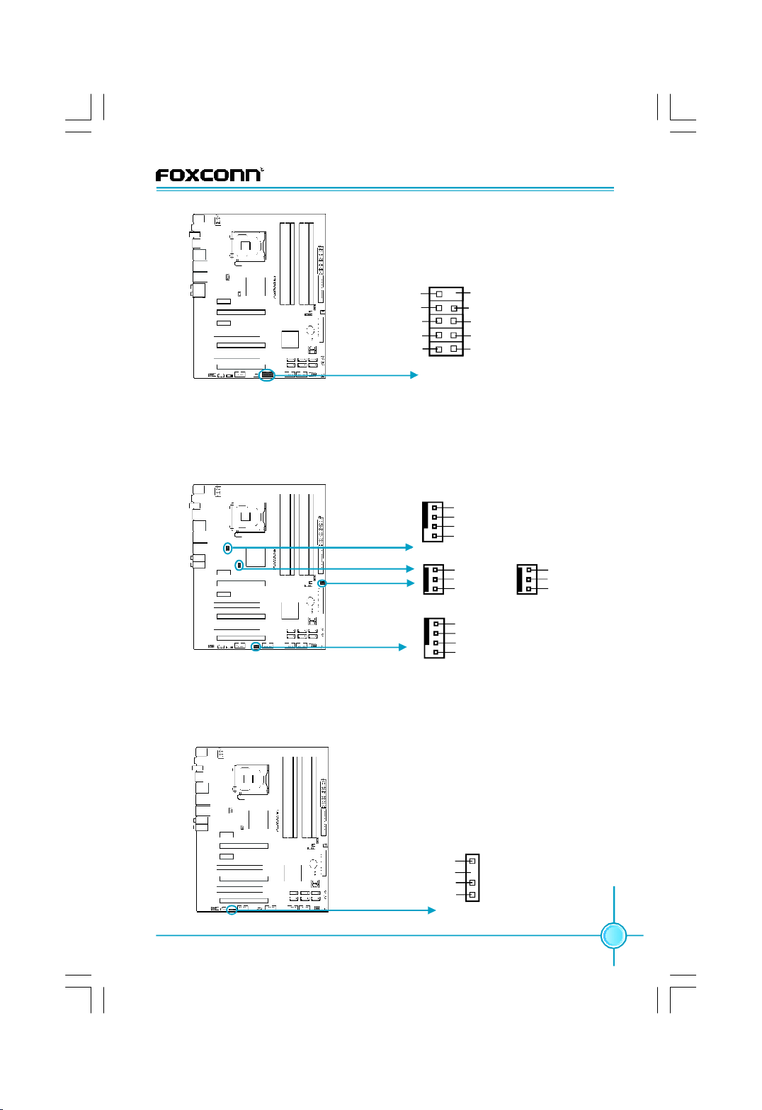
IEEE 1394a Connector: F_1394
The 1394 expansion cable can be connected to either the front (provided that
the front panel of your chassis is equipped with the appropriate interface) or
real panel of the chassis.
18
Page 25
Chapter 2 Installation Instructions
10 9
GND
+12V
TPB -
GND
TPA -
IEEE 1394a Connector
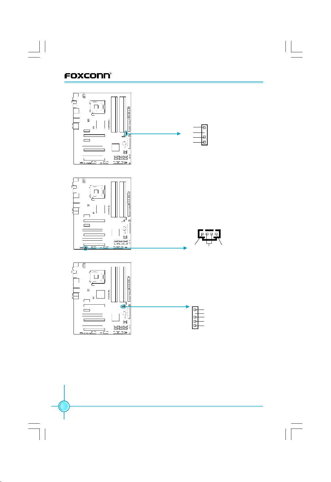
Fan Connectors: CPU_FAN, SYS_FAN, FAN1/2/3
There are five fan connectors on this motherboard. The fan speed can be
detected and viewed in “Hardware Health Configure” section of the CMOS
Setup. These fans will be automatically turned off after the system enters
S3, S4 and S5 mode.
Empty
+12V
TPB +
GND
TPA +
12
F_1394
1
GND
POWER
SENSE
CONTROL
CPU_FAN
Fan Connectors
1
FAN1
1
SYS_FAN
GND
+12V
SENSE
GND
POWER
SENSE
CONTROL
1
GND
+12V
Empty
FAN2/3(下
一版)
Digital Audio Connector: SPDIF_OUT
This connector is for an additional Sony/Philips Digital Interface (S/PDIF)
port. Connect the module cable to this connector, then install the module
to a slot opening at the back of the system chassis.
1
SPDIF_OUT
Digital Audio Connector
+5V
Empty
SPDIF_OUT
GND
19
Page 26
Chapter 2 Installation Instructions
Speaker Connector: SPEAKER
The speaker connector is used to connect
speaker of the chassis.
Speaker Connector
CD_IN Connector
IrDA Connector
+5V
Empty
NC
SPKJ
1
SPEAKER
Audio Connector: CD_IN
The connector allows you to receive stereo audio input from sound sources such
as a CD-ROM.
1
GND
CD_L
CD_R
CD_IN
IrDA Connector: IR
This header supports wireless transmitting and receiving device. Before using this
founction, configure the settings of “Serial
port2 Mode” in CMOS Setup.
1
+5V
Empty
IRRX
GND
IRTX
IR
Chassis Intruder Connector: INTR
The connector connects to the chassis security switch on the case. The system
can detect the chassis intrusion through the status of this connector. If the
connector has been closed, the system will send a message.
20
Page 27

Chapter 2 Installation Instructions
1
INTRUDERJ GND
INTR
Chassis Intruder Connector
Jumpers
This section explains how to setup jumpers. You should read the following
content carefully prior to modifying any jumper settings.
Attention
The jumpers on the motherboard, pin 1 can be identified by the
bold silkscreen next to it. and in this manual, pin 1 is simply labeled as “ 1”.
Clear CMOS Jumper: CLR_CMOS
The CLR_CMOS jumper allows you to clear the data in CMOS. The data
includes system setup information such as system password, data, time,
and system setup parameters. To clear and reset the system parameters to
default setup, please do as follows:
1. Turn off the computer and unplug the power cord from the power supply.
2. Move the jumper cap from pins 2-3 (default) to pins 1-2. Keep the cap on
pins 1-2 for several seconds, then move the cap back to pins 2-3.
3. Plug the power cord and turn on the computer, press <Del> to enter BIOS
setup during POST to load defaults.
1
Clear
1
Normal
(default)
Clear CMOS Jumper
CLR_ CMOS
21
Page 28

Chapter 2 Installation Instructions
Onboard Buttons
CLS_CMOS Button
(Yellow)
Reset Button
(Black)
Power on Button
(Red)
Onboard Buttons
Power on and Reset Buttons:
Power On / Off / Reset buttons are located directly on the motherboard PCB, so
you can easily start and reset your system whilst testing it on the workbench.
CLS_CMOS Button:
Easily reset CMOS on the workbench, when recovering from failed overclock
attempt.
Attention:
1. Make sure the power supply is turned off before pressing the
CLS-CMOS button to clear CMOS.
2. Press down the CLS_CMOS button and keep this for a moment
to clear CMOS completely.
Onboard LED Debug
Onboard LED Debug
Onboard LDE Debug:
2-digit LED readout displays hardware status and enables quick error diagnosis.
22
LED Debug
Page 29

Chapter 3 BIOS Description
Chapter
This chapter tells how to change system settings through the
BIOS Setup menus. Detailed descriptions of the BIOS param-
eters are also provided.
You have to run the Setup Program when the following cases
occur:
1.An error message appears on the screen during the system
2.You want to change the default CMOS settings.
This chapter includes the following information:
v Hardware Health Configure
3
3
POST process.
v Enter BIOS Setup
v Main Menu
v Standard BIOS Features
v Advanced BIOS Features
v Advanced Chipset Features
v PCI/PNP Resource Management
v Boot Configuration Features
v Power Management Features
v BIOS Security Features
v Fox Central Control Unit
v Load Optimal Defaults
v Load Failsafe Defaults
v Discard Changes
v Save Changes and Exit
v Discard Changes and Exit
23
Page 30

Chapter 3 BIOS Description
Enter BIOS Setup
The BIOS is the communication bridge between hardware and software,
correctly setting up the BIOS parameters is critical to maintain optimal system
performance. Power on the computer, when the following message briefly
appears at the bottom of the screen during the POST (Power On Self Test),
press <Del> key to enter the BIOS CMOS Setup Utility.
Press TAB to show POST Screen, DEL to enter SETUP
Note:
We do not suggest that you change the default parameters in the
BIOS Setup, and we shall not be responsible for any damage that
result from any changes that you make.
Main Menu
The main menu displays a list of options that are available. Use the arrow keys
to highlight an item, and execute the item by pressing <Enter>.
Main Menu
The items in the main menu are explained as below:
1. Standard BIOS Features
The basic system configuration can be set up through this menu.
2. Advanced BIOS Features
The advanced system features can be set up by the menu.
3. Advanced Chipset Features
The values for the chipset can be changed through this menu, and the sys tem performance can be optimized.
24
Page 31

Chapter 3 BIOS Description
4. PCI/PNP Resource Management
The system’s PCI/PNP settings and parameters can be modified through
this menu.
5. Boot Configuration Features
The menu is used for boot setting.
6. Power Management Features
Through this menu all the items of Green function features can be set up.
7. BIOS Security Features
The supervisor and user password can be set up through this menu.
8. Fox Central Control Unit
This menu is used to configure some special features of CPU、Memory
and all voltage values for overclocking.
9. Hardware Health Configure
This will display the current status of your PC.
10.Load Optimal Defaults
The optimal performance settings can be loaded through this menu. However,
the stable default values may be affected.
11.Load Failsafe Defaults
The Failsafe defaults BIOS settings can be loaded through this menu.
12.Discard Changes
Give up all CMOS value changes.
13.Save Changes and Exit
Save CMOS value settings to CMOS and exit setup.
14.Discard changes and Exit
Abandon all CMOS value changes and exit setup.
25
Page 32

Chapter 3 BIOS Description
1. Standard BIOS Features
Standard BIOS Features Menu
vSystem Time / Date
Use this item to change the system time and date. Highlight System Time
or System Date using <Arrow> key. Enter new values through the keyboard
with <hour><minute><second> and <day><month><date><year> format.
Press [ENTER], [TAB] or [SHIFT-TAB] key to select a field. Use [+] or [-] to
configure system time and date.
vFloppy A
This item allows you to select the type of FDD to be installed. Including
[360KB, 51/4 in], [1.2MB, 51/4in], [720KB, 31/2 in], [1.44MB, 31/2 in], [2.88 MB, 31/2 in].
2. Advanced BIOS Features
Advanced BIOS Features Menu
26
Page 33

Chapter 3 BIOS Description
2.1 IDE Configuration
Scroll to this item and press <Enter> to view the following screen:
IDE Configuration Menu
vSATA#1 / SATA#2 Configuration
This item is used to configure SATA 1 / SATA 2.
vConfigure SATA#1 as
The option uses to set the type of SATA.
vPrimary / Secondary / Third / Fourth / Fifth / Sixth IDE Master &
Primary / Secondary /Sixth IDE Slave
Leave this item at auto to enable the system to automatically detect and con-
figure IDE device on the channel. Press <Enter> to access its sub menu.
vHard Disk Write Protect
Set this item to protect the hard disk drive from being overwritten.
vIDE Detect Time Out (Sec)
This item is used to stop the BIOS from searching for IDE devices within the
specified number of seconds. Basically, this allows you to fine-tune the set-
tings to allow for faster boot times. Adjust this setting until a suitable timing
that can detect all IDE disk drives attached is found.
27
Page 34

Chapter 3 BIOS Description
2.2 USB Configuration
Scroll to this item and press <Enter> to view the following screen:
USB Configuration Menu
vLegacy USB Support
Legacy USB support refers to the USB mouse and USB keyboard support.
[Disabled]: to prevent the use of any USB device in DOS or during system boot.
[Enabled]: to allow the use of USB device during boot and while using DOS.
[Auto]: auto detects USB keyboard or mouse and if found, allows it to utilize
during boot and while using DOS.
vUSB 2.0 Controller Mode
This item is used to set the transmission rate mode of USB 2.0.
vBIOS EHCI Hand-Off
This item is used to enable or disable the BIOS EHCI Hand-Off.
This is a workaround for OSes without EHCI hand-Off support .
The EHCI ownership change should claim by EHCI driver.
2.2.1 USB Mass Storage Device
Press <Enter> to go to the next page sub menu.
vUSB Power Mode
This item is used to set the mode of USB power.
28
Page 35

Chapter 3 BIOS Description
USB Mass Storage Device Menu
vUSB Mass Storage Reset Delay
Number of seconds POST waits for the USB mass storage device after start
unit command.
vEmulation Type
This item is used to select the type of emulation used during the boot sequence.
2.3 SuperIO Configuration
Scroll to this item and press <Enter> to view the following screen:
SuperIO Configuration Menu
vOnBoard Floppy Controller
This item is used to enable or disable floppy controller.
vSerial Port1 / 2 Address
This item specifies the base I/O port address and interrupt request address
of serial port 1 / 2.
Note: Do not try to set the same values for serial ports 1 and 2.
29
Page 36

Chapter 3 BIOS Description
vSerial Port2 Mode
This item is used to set the serial Port2 mode.The available setting values
are: [Normal], [IrDA 1.6us] and [IrDA 3/16 bit].
vIR Duplex Mode
Select full or half duplex mode for serial port 2.
vIRTX Pin Select
This item allows BIOS to select transmit pin in normal condition or inverse the
IRTX.
vIRRX Pin Select
This item allows BIOS to select receiver pin in normal condition or inverse the
IRRX.
vIR TX to Rx Delay Select
Allows BIOS to select IR from Tx to Rx 4 characters time delay for serial port 2.
vIR RX to Tx Delay Select
Allows BIOS to select IR from Rx to Tx 4 characters time delay for serial port 2.
2.4 AHCI Configuration
Scroll to this item and press <Enter> to view the following screen:
AHCI Configuration Menu
vAHCI CD/DVD Boot Time out
This option is used to set AHCI CD / DVD boot time out.
vAHCI Port0/ 1 / 2 / 3 / 4 / 5
While entering Setup, BIOS auto detects the presence of IDE devices. This
displays the status of auto detection of IDE devices.
30
Page 37

Chapter 3 BIOS Description
2.5 Smbios Configuration
Scroll to this item and press <Enter> to view the following screen:
Smbios Configuration Menu
vSmbios Smi Support
Enable SMBIOS SMI wrapper support for PnP function 50h-54h.
2.6 MPS Configuration
Scroll to this item and press <Enter> to view the following screen:
MPS Configuration Menu
vMPS Revision
The BIOS support versions of the 1.1 and 1.4 of the intel multiprocessor
specification. Select the version supported by the operating system running
on the computer.
31
Page 38

Chapter 3 BIOS Description
2.7 OBD Configuration
Scroll to this item and press <Enter> to view the following screen:
OBD Configuration Menu
v1394 Controller
This item enables the onboard 1394 controller.
vRTL8110 / RTL8111B Lan Controller
This item is to activate the function of onboard RTL8110 or RTL8111 LAN
controller.
vRTL8110 / RTL8111B Lan BOOTROM
This item is used to enable or disable the onboard LAN BootROM.
vJMicron 36x ATA Controller
Select ATA controller operation mode.
3. Advanced Chipset Features
Advanced Chipset Features Menu
32
Page 39

Chapter 3 BIOS Description
3.1 North Bridge Configuration
Scroll to this item and press <Enter> to view the following screen:
North Bridge Configuration Menu
vMemory Remap Feature
Enable to allow remapping of overlapped PCI memory above the total physical
memory.
vMemory Hole
This reserves the 15MB to 16MB memory address space for use of ISA expan
sion card.
vInitate Graphic Adapter
Select which graphics controller to use as the primary boot device.
PEG Port Configuration
vPEI-E1 / E2_X16
This item is used to configure PEI-E1 / E2_X16.
3.2 South Bridge Configuration
Scroll to this item and press <Enter> to view the following screen:
South Bridge Configuration Menu
33
Page 40

Chapter 3 BIOS Description
vUSB Functions
This item enable or disable USB function.
vUSB Port Configure
The item is used to set USB port.
vUSB 2.0 Controller
This item is used to enable or disable the Enhanced Host Controller Interface
for USB.
vHDA Controller
Set HDA controller enabled.
vSMBUS Controller
This item is used to set SMBUS controller enabled.
vReserved Page Route
This item is used to configure reserved page route.
vSLP_S4# Min. Assertion Width
The option specifies SLP_S4#Min. Assertion Width.
vRestore on AC Power Loss
What action the PC will take with the power supply when it restores after the AC
power loss.
PCIE Ports Configuration
vPCIE Port 0 / 1 / 2 / 3
This item is used to set PCIE port 0 / 1 / 2 / 3.
vPCIE High Priority Port
Whether to set the high priority of PCIE port.
vPCIE Port 0 / 1 / 2 / 3 / 4 / 5 IOxAPIC Enable
Whether to enable PCIE port 0 / 1 / 2 / 3 / 4 / 5 I/OxAPIC.
34
Page 41

Chapter 3 BIOS Description
4. PCI/PNP Resource Management
PCI/PNP Resource Management Menu
vClear NVRAM
This sets the operating mode of the boot block area of the BIOS FLASH ROM
to allow programming in the Yes setting.
vPlug & Play O/S
Set this value to allow the system to modify the settings for plug and play
operating system support.
[No]: The setting is for operating systems that do not meet the plug and play
specifications. It allows the BIOS to configure all the devices in the system.
[Yes]: The setting allows the operating system to change the inerrupt, I/O, and
DMA setting. Set this vaule if the system is running plug and play aware oper-
ating system.
vPCI Latency Timer
Set this value to allow the PCI latency timer to be adjusted. This item sets the
latency of all PCI devices on the PCI bus.
vAllocate IRQ to PCI VGA
Set this item to allow or restrict the system from giving the VGA adaper card an
interrupt address.
vPalette Snooping
Whether to allow the systme to modify the palette snooping settings.
vPCI IDE BusMaster
Set this value to allow or prevent the use of PCI IDE busmastering.
vOffBoard PCI/ISA IDE Card
This item is used to allow the offboard PCI / ISA IDE card to be selected.
35
Page 42

Chapter 3 BIOS Description
vIRQ3 / 4 / 5 / 7 / 9 / 10 / 11 / 14 / 15 & DMA Channel 0 / 1 / 3 / 5 / 6 / 7
The items are for IRQ / DMA to decide whether or not to let PnP automatically
configrate. Specified IRQ / DMA is available to be used by PCI / PnP devices.
vReserved Memory Size
This item is used to set the size of memory block to reserve for legacy ISA
devices.
5. Boot Configuration Features
Boot Configuration Features Menu
5.1 Boot Settings Configuration
Scroll to this item and press <Enter> to view the following screen:
Boot Settings Configuration Menu
vQuick Boot
While Enabled, this item allows the BIOS to skip certain POST tests to boot
faster.
vQuiet Boot
Set this value to allow the boot up screen options to be modified between
POST messages or OEM logo.
36
Page 43

Chapter 3 BIOS Description
vAddOn ROM Display Mode
Set this item to display addon ROM (read-only memory) messages.
vBootup Num-Lock
The item defines if the keyboard Num Lock key is active when the computer
system is boot up.
vPS/2 Mouse Support
Whether to allow the system to use PS/2 Mouse while booting.
vWait For ‘F1’ If Error
The item is used to set whether wait for “F1” key to be pressed if error occurs.
Enabling this option causes the system to pause the POST if it encounters an
error, and wait for user to press the F1 key before resuming.
vHit ‘DEL’ Message Display
The item uses to set whether shows the information about press DEL to run
BIOS setup in POST.
vInterrupt 19 Capture
This option is used to set interrupt 19 capture.
5.2 Boot Device Priority
Scroll to this item and press <Enter> to view the following screen:
Boot Device Priority Menu
v1st Boot Device
This item specifies the boot sequence from the available device.
Note: A device enclosed in parenthesis has been disabled in the corre sponding type menu.
37
Page 44

Chapter 3 BIOS Description
5.3 Removable Drives
Scroll to this item and press <Enter> to view the following screen:
v1st Drive
The item is used to specify the boot sequence from the available removable
drives.
Removable Drives Menu
6. Power Management Features
Power Management Features Menu
6.1 APM Configuration
Scroll to this item and press <Enter> to view the following screen:
38
Page 45

Chapter 3 BIOS Description
APM Configuration Menu
vPower Button Mode
This item specifies how the externally mounted power button on the front of
the computer chassis is used.
vAdvanced Resume Event Controls
Resume On PME#
Disable / Enable PME to generate a wake event.
Resume On PCIE-PME#
Use this option to enable PCIE-PME to wakeup the system from a power
saving mode.
Resume On RTC Alarm
Use this option to enable RTC alarm to wakeup the system from a power
saving mode.
6.2 ACPI Configuration
Scroll to this item and press <Enter> to view the following screen:
ACPI Configuration Menu
39
Page 46

Chapter 3 BIOS Description
6.2.1 General ACPI Configuration
Press <Enter> to go to the following sub menu.
General ACPI Configuration Menu
vSuspend mode
This item is used to select the ACPI mode used for system suspend.
vRepost Video on S3 Resume
This item is used to set if opened the repost video on S3 resume function, it
allows the system to initialize the PCI BIOS POST from S3 (suspend to RAM)
sleep mode.
6.2.2 Advanced ACPI Configuration
Press <Enter> to go to the following sub menu.
Advanced ACPI Configuration Menu
vACPI Version Features
This item is used to select the ACPI version.
vACPI APIC support
This item is used to set if add the ACPI APIC table pointer to RSDT pointer list.
40
Page 47

Chapter 3 BIOS Description
vAMI OEMB table
Set this value to allow AMI OEMB table enable support.
vHeadless mode
This option is used to update the ACPI FACP table to indicate headless
operations.
6.2.3 Chipset ACPI Configuration
Press <Enter> to go to the following sub menu.
Chipset ACPI Configuration Menu
vEnergy Lake Feature
This item is to activate the function of energy lake.
vAPIC ACPI SCI IRQ
Whether to enable to APIC ACPI SCI IRQ function.
vUSB Device Wakeup From S3
Use this item to enable USB devices to wakeup the system from a power
saving mode.
vHigh Performance Event Timer
Enable the item to accurate control of multimedia events.
vEnable KB MS wake from S5
Enable KB MS wakeup the system from S5.
41
Page 48

Chapter 3 BIOS Description
7. BIOS Security Features
BIOS Security Features Menu
vChange Supervisor / User Password
Install or change supervisor / user password.
vUser Access Level
This item is used to set user access level.
vClear User Password
Press <Enter> to clear user password.
vPassword Check
Whether to check the password.
vBoot Sector Virus Protection
The item is used to protect your PC from being affected by viruses.
42
Page 49

Chapter 3 BIOS Description
8. Fox Central Control Unit
Fox Central Control Unit menu
8.1 CPU Configuration
Scroll to this item and press <Enter> to view the following screen:
CPU Configuration Menu
vSuper Clock Free
Enables or disables CPU clock free. It is available only when the CPU is not
the XE CPU and EIST is enabled.
vIntel(R) SpeedStep(tm) tech
Whether to enable the Intel speedstep technology.
vCPU Ratio Setting
This item is used to set CPU ratio.
vC1E Support
This item is used to enable or disable C1E (Enhanced Halt State) function.
Note: This function will not be displayed until a CPU supports C1E function.
43
Page 50

Chapter 3 BIOS Description
vAdjacent Cache Line Prefetch
Enables or disables adjacent cache line prefetch function.
vHardware Prefetcher
Enables or disables hareware prefetcher feature.
vIntel(R) Virtualization Tech
Virtualization solutions allow a platform to run multiple operating systems and
applications as independent virtual machines. Using virtualization capabilities,
one computer system can function as multiple "virtual" systems.
vExecute-Disable Bit Capability
When disabled, force the XD feature flag to always return 0.
vPECI
Enable PECI(Platform Environment Control Interface) to provide excellent digi-
tal thermal control.
vCore Multi-Processing
This item is used to enable or disable Core Multi-Processing function.
8.2 Memory Timing Config
Scroll to this item and press <Enter> to view the following screen:
vDRAM Frequency
This item is used to set DRAM frequency.
vConfigure DRAM Timing by SPD
Whether to let the BIOS read the DRAM module SPD data and automatically
set to the values stored in it.
vDRAM CAS# Latency
This Item controls the CAS latency, which determines the timing delay (in clock
cycles) before SDRAM starts a read command after receiving it.
44
Memory Timing Config Menu
Page 51
Chapter 3 BIOS Description
vDRAM RAS# ro CAS# Delay
This item allows you to select a delay time (in clock cycles) between the CAS
and RAS strobe signals.
vDRAM RAS# Precharge
This item allows you to select the DRAM RAS precharge time (in clock cycles).
vDRAM RAS# Activate to Prec
This item allows you to select the DRAM RAS activate to precharge time (in
clock cycles).
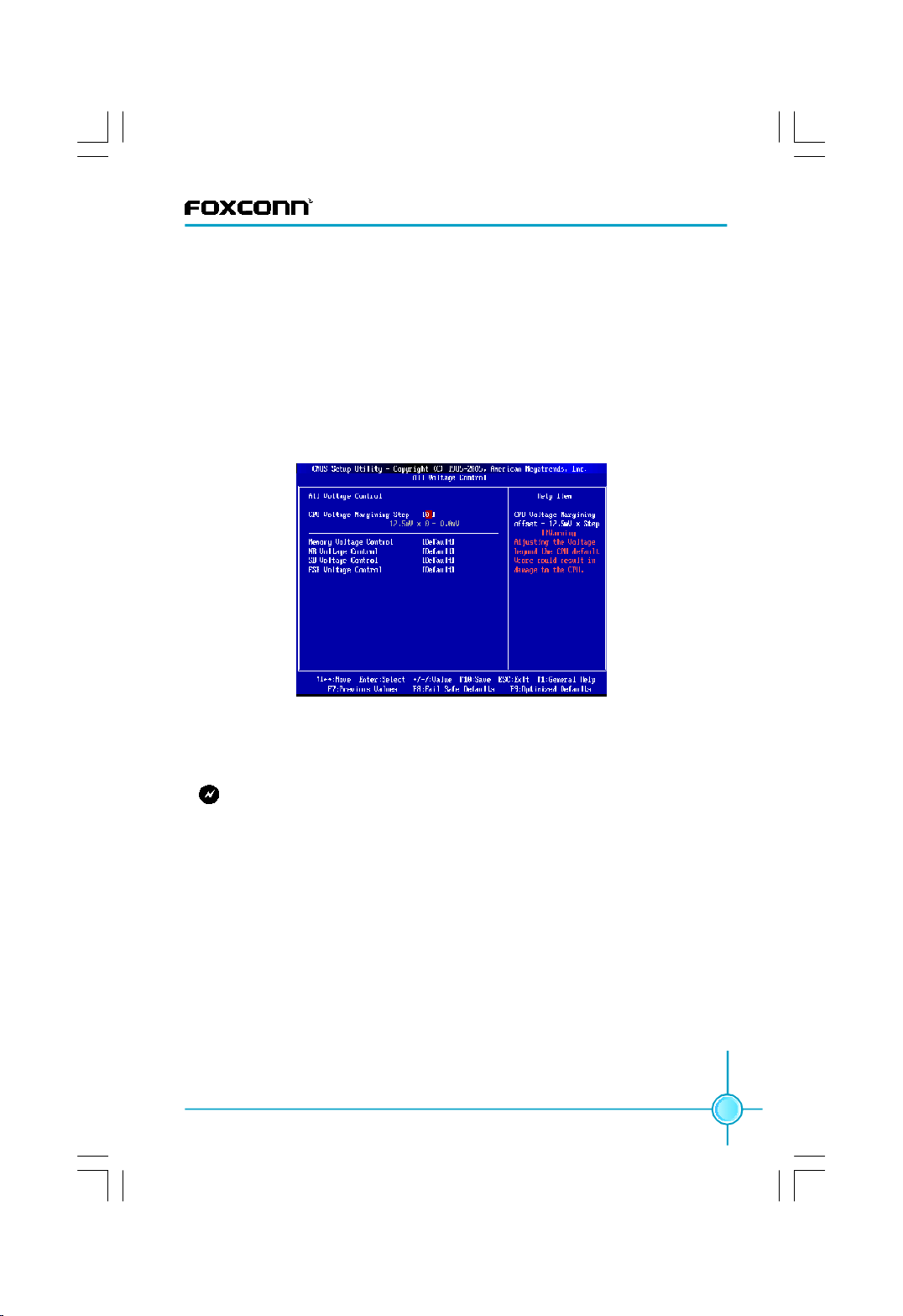
8.3 All Voltage Control
Scroll to this item and press <Enter> to view the following screen:
All Voltage Control Menu
vCPU Voltage Margining Step
This item is used to set CPU Voltage Margining Step. CPU Voltage Margining
offset = 12.5mV x Step.
Warning: Adjusting the Voltage beyond the CPU default Vcore could re-
sult in damage to the CPU.
vMemory / NB / SB / FSB Voltage Control
This item is used to change Memory / NB / SB / FSB Voltage.
8.4 Fox Intelligent Stepping
You can select different overclocking options by this item.
8.5 ******* Ratio and Clock Setting *******
vCPU Frequency Setting
This item is used to set CPU frequency.
vCPU Frequency : Memory Speed
The option specifies CPU frequency : memory speed.
vPCIE Frequency Setting
This item is used to set PCIE frequency.
vPCI Clock
This item is used to set PCI clock.
45
Page 52

Chapter 3 BIOS Description
8.6 ************ Miscellaneous ************
vPCI Clock Auto Detect
This item is used to set whether allow the system to supply the PCI slot bus
clock if system detected PCI add-on card on the slot.
vPCIE / CPU Spread Spectrum
If you enable PCIE / CPU spread spectrum, it can significantly reduce the EMI
(Electro-Magnetic Interference) generated by the system.
vSmart Power LED
Whether to enable the function of smart power LED.
vSmart Boot Menu
Whether to enable the function of smart boot menu.
9. Hardware Health Configure
Hardware Health Configure Menu
vH/W Health Function
Enables hardware health monitoring device.
vCPU / Sys Temperature, CPU / Sys / Fan1 Fan Speed, Vcore / Vdimm / Vmch
/ 5v / 12v / 3.3v / VCC / VSB / VBAT
The values will automatically detected by the system.
vChassis Intrusion
Whether to enable the function of chassis intrusion.
vCPU / Sys FAN Mode Setting
Select CPU / System fan mode.
vTemperature Limit of Highe / Secon / Third / Lowes
Set temperature limit of highest / second / third / lowest. Min is 0 and the Max
is 127.
46
Page 53

Chapter 3 BIOS Description
vFan Highest / Second / Third / Fourth / Lowest Setting
Set Fan Highest / Second / Third / Fourth / Lowest Setting. Min is 0 and the Max
is 100.
10. Load Optimal Defaults
Automatically sets all setup options to a complete set of default settings when
you select this option. This Optimal settings are designed for maximum system
performance, but may not work best for all computer applications. In particular,
do not use the optimal setup options if your computer is experiencing system
configuration problems.
Select Load Optimal Defaults from the Exit menu and press <Enter>
Load Optimal Defaults?
[Ok] [Cancel]
appears in the window. Select Ok to load optimal defaults.
11. Load Failsafe Defaults
Automatically sets all setup options to a complete set of default settings when
you select this option. This Failsafe settings are designed for maximum system
stability, but not maximum performance. Select the Failsafe Setup options if
your computer is experiencing system configuration problems.
Select Load Failsafe Defaults from the Exit menu and press <Enter>.
Load Failsafe Defaults?
[Ok] [Cancel]
appears in the window. Select Ok to load Failsafe defaults.
12. Discard Changes
Select Discard Changes from the Exit menu and press <Enter>.
Discard Changes?
[Ok] [Cancel]
Select Ok to discard changes.
13. Save Changes and Exit
When you have completed the system configuration changes, select this option
to leave setup and reboot the computer, so the new system configuration parameters can take effect. Select Save Changes and Exit from the Exit menu and
press <Enter>.
47
Page 54

Chapter 3 BIOS Description
Save Configuration Changes and Exit?
[Ok] [Cancel]
appears in the window. Select Ok to save changes and exit.
14. Discard Changes and Exit
Select this option to quit setup without making any permanent changes to the
system configuration. Select Discard Changes and Exit from the Exit menu and
press <Enter>.
Discard Changes and Exit?
[Ok] [Cancel]
appears in the window. Select Ok to discard changes and exit.
48
Page 55

Chapter 4 Driver CD Introduction
Chapter
This chapter will introduce how to use bundled software.
This chapter provides the following information:
4
4
v FOX ONE
v FOX LiveUpdate
v FOX LOGO
v FOX DMI
49
Page 56

Chapter 4 Directions for Bundled Software
FOX ONE
FOX ONE is a powerful utility for easily modifying system settings. It also allows
users to monitor various temperature values, voltage values, frequency and fan
speed at any time.
With FOX ONE, you can modify system performance settings such as bus speed,
CPU voltage, fan speed and other system performance options that are supported
by the BIOS and you also can monitor hardware temperature, voltage, frequency
and fan speed.
Supported Operating Systems:
-Windows 2000
-Windows XP (32-bit and 64-bit)
-Windows 2003 (32-bit and 64-bit)
-Windows Vista (32-bit and 64-bit)
Using FOX ONE:
1. Main Page
Show CPU Information
50
Use the toolbar to navigate to
other pages
Alert Lamp
Switch Button
Skin Button
Exit
Minimum
Configuration
Homepage
Monitor Frequency/Voltage/Fan speed/Temperature value
Page 57

Chapter 4 Directions for Bundled Software
Toolbar
Use the toolbar to navigate to other pages.
Alert Lamp
When the system is in healthy status, the alert lamp color is green. And if the system
is in abnormal status, the alert lamp color will turn red.
Switch Button
Click this button, it will simplify the interface to HW monitor information bar as the
below figure shows. The bar could help you to monitor if your system is in the
healthy status at any time.
Click here to return to
previous status
Skin Button
Click this button, you will see the additive figures such as “Crystal”and “Rock”.
Please select your favorite skin.
Apply the changes
Cancel the changes
Exit
Click this button to exit the program.
Minimum
Click this button to minimize the window.
Click the new skin
picture to select the
new skin
51
Page 58

Chapter 4 Directions for Bundled Software
Configuration
This function is used to configure the parameters for the program. It determines
which items will be shown in simple mode. Besides, it also provides F.I.S cali-
bration function which will recalibrate the CPU’s loading. F.I.S calibration func-
tion is optional.
Homepage
Click this button to visit Foxconn motherboard website.
2. CPU Page - CPU Control
This page is used to select and run the CPU frequency to determine the current
performance level of the system. You can adjust manually or select “Auto
Overclock”. Otherwise, it also provides FOX Intelligent Stepping, but this func-
tion is optional.
Go to CPU page
52
Reset the
changes
Select the different
benchmarks
Apply the
changes
Close this page
Auto
Overclocking
Ajust by manual
Page 59

Chapter 4 Directions for Bundled Software
3. Freq. Page - Frequency Control
This page enables you to set memory and PCI Express frequency manually.
Go to Freq. page
Close this page
Select the option
you want to set
Adjust manually
Reset the changes
Apply the changes
4.1 Limit Setting - CPU Temp.
This page allows you to set CPU high limit temperature and enable the alert
function.
Go to limit Setting page
Show current CPU
temperature value
Enable alert function
when the CPU
temperature is higher
than high limit value
Show current high
limit value of CPU
temperature
Set high limit by
dragging the lever
53
Page 60

Chapter 4 Directions for Bundled Software
4.2 Limit Setting - Sys Temp.
This page helps you to set system high limit temperature and enable the alert
function.
Show current system
temperature value
Enable alert function
when the system
temperature is higher
than high limit value
Show current high
limit value of system
temperature
Set high limit by
dragging the lever
4.3 Limit Setting - CPU Fan
This page allows you to set CPU fan low limit rpm (revolutions per minute) and
enable the alert function.
54
Show current CPU
fan rpm value
Enable alert function
when the CPU fan rev
is lower than low limit
rpm value
Show current low limit
rpm value of CPU fan
Set low limit rpm by
dragging the lever
Page 61

Chapter 4 Directions for Bundled Software
4.4 Limit Setting - Sys Fan
This page enables you to set system low limit rpm (revolutions per minute) and
enable the alert function.
Show current system
fan rpm value
Enable alert function
when the system fan
is lower than low limit
rpm value
Show current low limit
rpm value of system
fan
Set low limit rpm by
dragging the lever
4.5 Limit Setting - FAN1 Fan
This page helps you to set FAN1 fan low limit rpm (revolutions per minute) and
enable the alert function.
Show current FAN1
fan rpm value
Enable alert function
when the FAN1 fan is
lower than low limit
rpm value
Show current low limit
rpm value of FAN1 fan
Set low limit rpm by
dragging the lever
55
Page 62

Chapter 4 Directions for Bundled Software
5. Voltage Page - Voltage Control
This page is used to set CPU voltage, memory voltage and northbridge voltage
manually.
Go to Voltage page
Select the option
you want to set
Adjust by manual
Reset the changes
Apply the changes
6. Fan Page - Fan Control
This page helps you to enable smart fan function or set fan speed manually.
Go to Fan page
Whether to enable
smart fan function
Set fan speed by
dragging the lever
Reset the changes
Apply the changes
56
Page 63

Chapter 4 Directions for Bundled Software
FOX LiveUpdate
FOX LiveUpdate is a useful utility to backup and update the system BIOS online
or locally. Drivers and utilities are aslo can be updated online.
Supported Operating Systems:
-Windows 2000
-Windows XP (32-bit and 64-bit)
-Windows 2003 (32-bit and 64-bit)
-Windows Vista (32-bit and 64-bit)
Using FOX LiveUpdate:
1.1 Local Update - BIOS Info.
This page tells you the system BIOS information.
Toolbar
Link to website
Minimum
Exit
Show current BIOS information
57
Page 64

Chapter 4 Directions for Bundled Software
1.2 Local Update - Backup BIOS
This page could backup your system BIOS. Please click “Backup” and key in a
BIOS name, then click “Save” to finish the backup operation.
Key in a BIOS name
Click here
1.3 Local Update - Update BIOS
This page helps to update your system BIOS. After click “Update”, there will show
warning message, please read it carefully. If you still want to continue, click “Yes”.
Then load a local BIOS file and follow the wizard to finish the operation.
58
Note:
FOX LiveUpdate will auto backup BIOS before update because we
have enabled this function in Configure option.
Page 65

Chapter 4 Directions for Bundled Software
2.1 Online Update - Update BIOS
This page lets you update your system BIOS from Internet. Click “start”, it will
search for the new BIOS from Internet. Then follow the wizard to finish the update
operation.
Click here
Current information
Search new BIOS
from Internet
Select BIOS to update
Browse detail
information
Update BIOS
Close the window
59
Page 66

Chapter 4 Directions for Bundled Software
2.2 Online Update - Update Driver
This page allows you to update your system drivers from Internet. Click “start”, it
will search for the new drivers. Then follow the wizard to finish the update operation.
Click here
Current information
Search new drivers
from Internet
Select the drivers to update
60
Browse detail
information
Install the selected
drivers
Close the window
Page 67

Chapter 4 Directions for Bundled Software
2.3 Online Update - Update Utility
This page helps you to update utilities from Internet. Click “start”, it will search for
the new utilities. Then follow the wizard to finish the update operation.
Click here
Current information
Search new utilities
from Internet
2.4 Online Update - Update All
This page enables you to update all of your system BIOS, Drivers, Utilities from
Internet. Click “start”, it will start searching. Then follow the wizard to finish the
update operation.
Click here
Current information
Search all new
BIOS/drivers/utilities
from Internet
61
Page 68

Chapter 4 Directions for Bundled Software
3.1 Configure - option
This page provides auto search options and version filter. After setting the auto search
options, the utility will work in the background and the related information will show in
a pop balloon notification.
Click here
Set auto
search options
Select search
which kind of
versions
62
Apply the changes
Reset to default value
Note:
When enable auto search function, FOX LiveUpdate will appear search-
ing result in a pop balloon notification. Double click icon, you can see
the detail information.
Double click here
Page 69

Chapter 4 Directions for Bundled Software
3.2 Configure - System
In this page, you can set the backup BIOS location and change different skin of
the utility.
Click here
Set the location of
download files or
auto backup BIOS
Select different skin
of the software
Reset to default value
Determine if the FOX liveUpdate can
auto run when the system starts up
Apply the changes
3.3 Configure - Advance
This page helps you to flash BIOS, Boot Block and Clear CMOS .
Click here
Select which BIOS ROM
to flash (Only available to
the motherboard with
backup BIOS ROM )
Select to flash Boot Block
Select to clear CMOS
Apply the changes
Attention:
we recommend that you keep the default setting unchanged to
avoid damagement.
Reset to default value
63
Page 70

Chapter 4 Directions for Bundled Software
4. About & Help
This page shows some information about FOX LiveUpdate.
Click here
Show information
about FOX LiveUpdate
FOX LOGO
FOX LOGO is a simple and useful utility to backup, change and delete the boot
Logo. The boot Logo is the image that appears on screen during POST (Power-
On Self-Test).
Supported Operating Systems:
-Windows 2000 -Windows XP (32-bit and 64-bit)
-Windows 2003 (32-bit and 64-bit) -Windows Vista (32-bit and 64-bit)
Using FOX LOGO:
Main Page
Main screen
Backup
Change
Delete
64
Exit
Minimize
Website
About
Page 71

Chapter 4 Directions for Bundled Software
Warning:
When you change Logo or delete current Logo, the system will flash BIOS
file automatically. During this time, please DO NOT shut down the application
and the system, or the motherboard will be damaged seriously.
FOX DMI
FOX DMI is a full DMI information viewer, and it supports three kinds of DMI Data
format: Report, Data Fields and Memory Dump.
Supported Operating Systems:
-Windows 2000 -Windows XP (32-bit and 64-bit)
-Windows 2003 (32-bit and 64-bit) -Windows Vista (32-bit and 64-bit)
Using FOX DMI:
Please operate this utility as the comments shows .
Click here to select
the DMI Data format
you need
Click here to select
the type you want
to view.
65
Page 72

Chapter 5 RAID Configuration
Chapter
This chapter will introduce Intel® RAID Configurations .
This chapter provides the following information:
5
5
v Introduction
v Installing Serial ATA Hard Disks
v BIOS Configuration
v RAID BIOS Configuration
v Creating a RAID Driver Floppy Disk
v Install OS on HDD with RAID set
66
Page 73

Chapter 5 RAID Configuration
Introduction
RAID (Redundant Array of Independent Disks) is a method of combining two hard
disk drives into one logical unit. The advantage of an Array is to provide better
performance or data fault tolerance. The motherboard comes with the Intel ICH9R.
The following RAID configurations are provided for users.
RAID 0 (Striping)
RAID 0 reads and writes sectors of data interleaved between multiple drives. If
any disk member fails, it affects the entire array. The disk array data capacity is
equal to the number of drive members times the capacity of the smallest member.
The striping block size can be set from 4KB to 128KB. RAID 0 does not support
fault tolerance.
RAID 1 (Mirroring)
RAID 1 writes duplicate data onto a pair of drives and reads both sets of data in
parallel. If one of the mirrored drives suffers a mechanical failure or does not
respond, the remaining drive will continue to function. Due to redundancy, the
drive capacity of the array is the capacity of the smallest drive. Under a RAID 1
setup, an extra drive called the “spare drive ” can be attached. Such a drive will be
activated to replace a failed drive that is part of a mirrored array. Due to the fault
tolerance, if any RAID 1 drive fails, data access will not be affected as long as
there are other working drives in the array.
RAID 5
RAID 5 Provides data striping at the byte level and also stripe error correction
information. This results in excellent performance and good fault tolerance. Level
5 is one of the most popular implementations of RAID.
RAID 10 (0+1)
RAID 10 is a combination of striping and mirroring. This configuration provides
optimal speed and reliability, but you need four SATA hard disks.
Intel® Matrix Storage
The Intel® Matrix Storage technology supports RAID 0 ,RAID 1, RAID 5, and RAID
10 (0+1) functions. It allows you to combine two RAID functions to get high performance with fault tolerance, big capacity or data safety provided by different RAID
function.
67
Page 74

Chapter 5 RAID Configuration
Installing Serial ATA Hard Disks
1. Install SATA hard disks into the drive bays.
2. Connect one end of the SATA cable to motherboard’s SATA onnectors and the
end to SATA hard disk.
3. Connect SATA power cable to the power connector of SATA hard disk.
BIOS Configuration
1. Enter the BIOS setup by pressing <Del> key during the POST.
2. Select the “Integrated Peripherals” form the “Main menu”, then select the
“OnChip IDE Device” item and press <Enter> to display the configuration
items.
3. Switch the “SATA Mode” option to [RAID].
4. Press <F10> to save the BIOS setting and then exit the BIOS setup program.
RAID BIOS Configuration
Enter RAID BIOS Setup
Enter the Intel® Matrix Storage Manager Option ROM Utility main menu by
pressing <Ctrl+I> keys When the following message appears on the screen
During the POST:
Press the <Ctrl-I> to enter Configuration Utility.
Note:
The RAID BIOS Setup pictures shown in this chapter are for reference
noly, please refer to the practical screen.
Creating RAID 0
1.Select “1.Create RAID Volume” from the utility main menu and press <Enter>.
The screen shows:
68
Page 75

Chapter 5 RAID Configuration
2. Enter a name for the RAID 0 according to the [DISK/VOLUME INFORMATION]
and press <Enter> to confirm.
3. Press <Tab> to switch to “RAID Level” item, and then use Up or Down arrow
key to select RAID0 (Stripe), press <Enter> to confirm.
4.Select “Disks” item and press <Enter> to display the [SELECT DISKS] screen
shown as below:
5. using up or down arrow key to select the hard disks you want to configure as
RAID 0from the list, then press <Space> key to confirm, and <Enter> key to
finish the selection.
6.Use Up or Down arrow key to select desired strip size when enter “Strip Size”
menu. The available values range from 4KB to 128KB. The strip value should
be based on the planned drive usage. Some suggested selections are listed
below. The default value is 128KB.
16K_Best for sequential transfer
64K_Good general purpose strip size
128K_Best performance for most desktops and workstations
69
Page 76

Chapter 5 RAID Configuration
7.key in the RAID volume “Capacity” value, then Press <Enter>. The default value
indicates the maximum capacity.
8.Select “Create Volume” and Press <Enter>, a warning message will appear
as below:
Press <Y> to create the volume and return to the main menu.
Press <N> to return to the “Create RAID Volume” menu.
Attention:
You will lost all data on the selected hard disk when you press <Y>
to create the volume.
Creating RAID 1
1.Select “1.Create RAID Volume” from the utility main menu and press <Enter>.
2. Key in a name for the RAID 1 according to the [DISK/VOLUME INFORMATION]
and press <Enter> to confirm.
70
Page 77

Chapter 5 RAID Configuration
3. Press <Tab> to switch to “RAID Level” item, and then use Up or Down arrow
key to select RAID1 (Mirror), press <Enter> to confirm.
4.Select “Disks” item and press <Enter> to choose the hard disks that you want
toconfigure as RAID 1.
5.key in the RAID volume “Capacity” value, then Press <Enter>. The default value
indicates the maximum capacity.
6.Select “Create Volume” and Press <Enter>, a warning message will appear
as below:
Press <Y> to create the volume and return to the main menu.
Press <N> to return to the “Create RAID Volume” menu.
Attention:
You will lost all data on the selected hard disk when you press <Y>
to create the volume.
Creating RAID 10 (0+1)
1.Select “1.Create RAID Volume” from the utility main menu and press <Enter>.
2. Key in a name for the RAID 10 according to the [DISK/VOLUME INFORMATION]
and press <Enter> to confirm.
3. Press <Tab> to switch to “RAID Level” item, and then use Up or Down arrow
key to select RAID10 (RAID 0+1), press <Enter> to confirm.
4.Select “Disks” item and press <Enter> to choose the hard disks that you want
toconfigure as RAID 10.
5.Use Up or Down arrow keys to select desired strip size for RAID10. The available values range from 4KB to 128KB. The default value is 64KB.
16K_Best for sequential transfer
64K_Good general purpose strip size
128K_Best performance for most desktops and workstations
71
Page 78

Chapter 5 RAID Configuration
6.key in the RAID volume “Capacity” value, then Press <Enter>. The default value
indicates the maximum capacity.
7.Select “Create Volume” and Press <Enter>, a warning message will appear
as below:
Press <Y> to create the volume and return to the main menu.
Press <N> to return to the “Create RAID Volume” menu.
Attention:
You will lost all data on the selected hard disk when you press <Y>
to create the volume.
Creating RAID 5 (Parity)
1.Select “1.Create RAID Volume” from the utility main menu and press <Enter>.
2. Key in a name for the RAID 5 according to the [DISK/VOLUME INFORMATION]
and press <Enter> to confirm.
3. Press <Tab> to switch to “RAID Level” item, and then use Up or Down arrow
keys to select RAID5 (Parity), press <Enter> to confirm.
4.Select “Disks” item and press <Enter> to choose the hard disks that you want
toconfigure as RAID 10.
5.Use Up or Down arrow key to select desired strip size for RAID 5. The available values range from 4KB to 128KB. The default value is 64KB.
16K_Best for sequential transfer
64K_Good general purpose strip size
128K_Best performance for most desktops and workstations
6.key in the RAID volume “Capacity” value, then Press <Enter>. The default value
indicates the maximum capacity.
7.Select “Create Volume” and Press <Enter>, a warning message will appear
as below:
72
Page 79

Chapter 5 RAID Configuration
Press <Y> to create the volume and return to the main menu.
Press <N> to return to the “Create RAID Volume” menu.
Attention:
You will lost all data on the selected hard disk when you press <Y>
to create the volume.
Delete RAID Volume
1.Select “2. Delete RAID Volume” in main menu and press <Enter>.
2.Use Up or Down arrow key to select the RAID set you want to delete and
press <Del>, the screen appears as below:
3.Press <Y> key to confirm the volume deletion, and press <N> to cancel the
operation.
Attention:
You will lost all data on the selected hard disk when you press <Y>
to delet the RAID volume.
Reset RAID
1.Select “3. Reset Disk to Non-RAID” in main menu and press <Enter> to reset
the RAID setting and delet all RAID structures on the drive. The following
message appears:
Are you sure you want to reset RAID data on selected? (Y/N):
2.Press <Y> to reset and press <N> to cancel the operation.
73
Page 80

Chapter 5 RAID Configuration
Exiting the Intel® Matrix Storage Manager Option ROM Utility
1.Select “4. Exit” in main menu and press <Enter>, The following message
appears:
Are you sure you want to exit? (Y/N):
2.Press <Y> to exit and press <N> to cancel the operation.
Creating a RAID Driver Floppy Disk
It requires a floppy disk with RAID driver when installing Windows Vista/XP/2000
Operating System on HDD that is included in a RAID set. There is a 32bit Intel
Matrix Storage Manager RAID Driver Floppy Disk that comes with the motherboard
package, if it can’t be used or you need the 64bit one, you have two ways to create
it by yourself in Windows environment:
To create RAID deiver Floppy Disk by using “Create RAID Drive Floppy”
1.Insert the attached Utility CD into the optical drive, the CD will automatically
displays the main menu.
2.Click on “Create RAID Drive Floppy”, and then select the type of RAID drive disk.
3.Insert a formatted FDD into the floppy disk drive.
4.Following the screen message to complete the drive floppy creating.
To create RAID driver Floppy Disk by copying
Copy the RAID driver from the CD to you floppy disk.
Directory: \Driver\IMSM\floppy32(32bit)
\Driver\IMSM\floppy64(64bit)
Note:
The RAID driver Floppy Disk has no use for Windows Vista which
has in-box driver it own.
Install OS on HDD with RAID set
1.Entering BIOS Setup during POST.
2.Set the “First Boot Device” to “CDROM”, save changes and exit the BIOS setup.
3.Insert the OS installation CD into the optical drive and restart the computer.
4.When the following picture appears, press <F6>, then insert the RAID driver
FDD to the floppy disk drive.
74
Page 81

Chapter 5 RAID Configuration
5.When the following picture appears, press <S> and then follow the screen
message to complete the OS installation.
Attention:
1. Make sure the floppy disk drive works normally.
2. Formatting will erase ALL data on your floppy disk, so please take care.
75
Page 82

Appendix
CrossFire
TM
Technology
Introduction
CrossFire
TM
technology is a recently introduced product from ATI Technologies
designed to dramatically improve the graphics performance of hardware and
software applications designed for gamers and other high-end users.
The CrossFireTM aspect requires the following components to be available in
order to appear as an option within CatalystTM Control Center:
· CrossFire
· CrossFire
· CrossFire
TM
Ready motherboard, such as Foxconn Digital Life Series: X38A
TM
Edition graphics card that works as the master graphics card
TM
Ready graphics card from the same brand-family that works as
the slave graphics card
For the detailed CrossFire Graphics cards support list on this motherboard,
please visit the website: http://www.foxconnchannel.com
Using CrossFireTM Technology
Step 1. Please uninstall any existing graphics card drivers that could possibly
create a conflict before attempting to install this display card.
Step 2. Install the Radeon CrossFireTM Edition graphics card (master) to
PCI-E1_X16 (Blue) slot.
Step 3. Install the Radeon CrossFireTM Ready graphics card (slave) to
PCI-E2_X16 (Blue) slot.
CrossFire
Edition graphics
card (Master)
TM
CrossFire
TM
Ready graphics
card (slave)
Step 4. Connect an auxiliary power source from the power supply to the graphics
card.
76
Page 83

Appendix
Power
Extension
Cable
Step 5. Correctly connect the DMS-59 cable to the DVI monitor connector and two
graphics cards that you install as shown.
Connect to master
graphics card DMS
Connect to monitor
connector
Connect to slave
graphics card DVI
connector
Step 6. Power on your computer and boot into OS(Windows® XP 32-bit with SP2
or Windows® XP Professional 64-bit Edition).
Step 7. Install Microsoft’s .NET Framework Version 1.1.Without it, The ATI Cata-
lystTM Control Center will not launch properly.
Step 8. Install the ATI graphics card drivers and restart your computer. Then you
will find “ATI Catalyst Control Center” on your desktop.
Step 9. Double-click the icon to launch it. Click “View”-->Select
“Advanced View” -->Click “CrossFireTM”-->Set “Enable CrossFireTM” to
Yes.
77
Page 84

Now you can enjoy the advanced CrossFireTM technology.
Note:
1. It is recommended to use 400-450 W power supply or above to enjoy
the benefit of CrossFireTM technology.
2. Two PCI Express x16 slots will work in x16 mode and one (Black)
will work in x4 mode when you use CrossFireTM technology.
3. The all-new Radeon X1300 and X1600 graphics cards do not need
a CrossFireTM Edition co-processor or external cable.
Appendix
78
 Loading...