

Fox Composites ME-163 KOMET Instructions For Use Manual
Fox Composites Co., Ltd.
February 2008 version: 1.0
FFooxx CCoommppoossiitteess MMee--116633 ‘‘KKoommeett’’

Instructions for Me-163 Komet model airplane
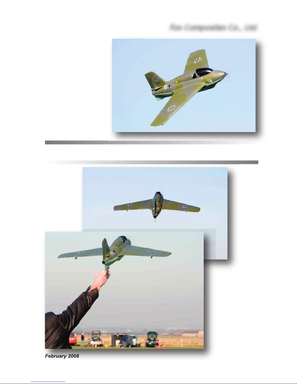
Thank you for purchasing the Messerschmitt 163 ‘Komet’ kit (37”, 94cms span) manufactured by
Fox Composites. These instructions are available as a free full-colour down-loadable Adobe Acrobat .pdf file on our website (www.fox-composites.com), and also on a CD-Rom in every kit box,
which you can print onto A4 paper if you wish. The .pdf file is viewable at 200%, without loss of
quality, so you can see the photos clearly. In addition, we have included high resolution versions
of all the photos used in the Manual, and some extra ones, on the CD for your assistance.
We strongly advise that you read this Instruction Manual completely, and make sure you understand all of it, before commencing assembly of the ‘Komet’ kit. Note that we have shown photos
of several different planes in these instructions; both the original ‘prototypes’, and all-red and allgrey ‘production’ kits - so please don’t get confused!
We hope you have much enjoyment and many safe flights with your ‘Komet’, and always welcome
feedback from Customers, and photos of your completed plane. If you have any technical questions about this product, or require spare parts, please contact us at:
email: jim@fox-composites.com alternative email: jimjet45@gmail.com
website: http://www.fox-composites.com
address: Fox Composites Co., Ltd. 19/88 Moo 5. Soi 53, Nongprue. Banglamung.
Pattaya. Chonburi 20150. Thailand.
Liability Exclusion
You have acquired a kit which can be assembled into a fully working and flying radio-controlled
model airplane when properly fitted with suitable equipment and accessories, and constructed according to the current instructions provided by Fox Composites Co., Ltd. for the kit.
However, as the manufacturers of this kit, Fox Composites Co,. Ltd cannot influence the manner
in which the model is built, fitted out and operated, and we are unable to control the methods and
equipment you use to install, operate and maintain the radio control system components. Therefore we are obliged to deny all responsibility and liability for any direct, or consequential, injury, loss,
damage or costs involved due to the incorrect or incompetent assembly, use or operation of this
product, or any circumstances connected with it. When operating this product you must assume
all responsibility for any resulting consequences.
Unless otherwise determined by binding law, Fox Composites Co,. Ltd. are excluded from paying
any compensation with regard to operation of our products. The maximum liability of Fox Composites Co., Ltd with regard to this product is limited to the amount that you actually paid for the
kit in all circumstances.
Fox Composites Co., Ltd are unable to monitor whether you follow our instructions with regard to
assembly, operation & maintenance of the model airplane. Therefore we are not able to guarantee or provide any contractual agreement with the operator or owner of the product that it will function correctly and safely. The operator of the product must rely on their own judgement in obtaining,
constructing and operating this model airplane.
Fox Composites Co., Ltd.
2
Safety
All model airplanes can provide a potential hazard for personal injury or damage to property if not
operated with care, and assembled and used in accordance with the instructions of the manufacturers of all the parts contained within it. It is your responsibility to operate and fly your ‘Komet’ in
accordance with all current laws & regulations governing model flying in the country of operation.
Before the first engine run, make sure that the motor, control surfaces, R/C gear and all servos with
their associated linkages are all attached securely. Double-check that heavy items, like batteries,
are attached very securely in the plane and cannot move.
Make absolutely sure that the Centre of Gravity is in the position shown at the end of this manual.
Carry out a proper range check with your R/C system, in both motor 'running' and motor 'off' states,
and ensure that the range achieved before fail-safe occurs is at least in accordance with the R/C
manufacturers minimum recommendations.
When starting and running the motor on the ground, make sure that the plane is firmly secured so
that it cannot move and ensure that all spectators are at least 10 metres behind or to the sides, or
far in front of the plane.
Adhesives
Gluing composite parts together does not require any special types of glue, but due to the high
flight speeds attainable with this type of model it is absolutely necessary to use high quality adhesives and proper gluing techniques to ensure airframe integrity, and safety.
For a strong glue joint it is equally important to use high-quality glue
and to prepare both parts to be joined properly. When joining any combination of fibreglass and wood parts together you must lightly sand
both parts (to provide a mechanical 'key' for the glue) and clean off
the dust caused by sanding, before joining them. You can use many
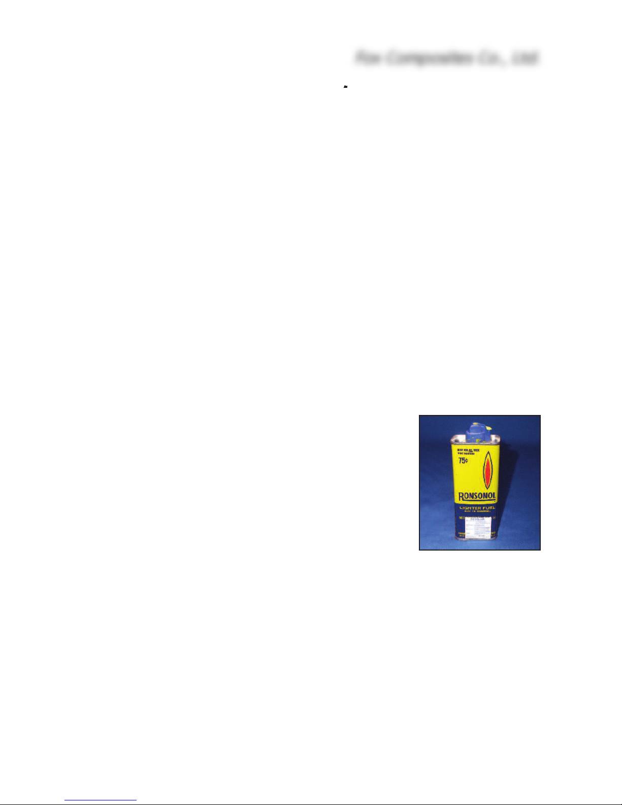
cleaning agents for this, however some of them may damage the 2pack polyurethane paint used to colour the parts in the mold. Therefore we highly recommend that you use de-natured alcohol or common
lighter-fluid, such as 'Ronsonol'. This is what we use at the factory,
and it can also be used to wipe uncured glue off painted surfaces, without damaging the paint.
When sanding the inside surface of the foam vacuum-sandwich parts (eg: wings and fin) be careful not to sand right thru' the lightweight glasscloth, as this will reduce the rigidity of the parts. Only
a light sanding with 120 - 240 grit is necessary, followed by cleaning.
The fuselage is a fibreglass and epoxy moulding, without a foam sandwich, and we suggest that
you sand the complete inside surface of it before starting any assembly - using 180 or 240 grit, or
red Scotchbrite pad. This will also remove any loose fibreglass strands.
At Fox Composites we only use 1st quality slow (24hr) laminating epoxy mixed with micro-balloons, ZAP 30 minute epoxy (mixed with micro-balloons), ZAP CA glues and Hysol 9462 thixotropic
epoxy for assembly and important joints, and can highly recommend these types. Micro-balloons
are added to all epoxy mixtures to increase the gap-filling ability, without adding weight. Milled
fibre is added to epoxy to increase the strength of the adhesive. Do not use any polyester-based
glues under any circumstances.
Fox Composites Co., Ltd.
3
B
efore starting assembly of your ‘Komet’ it is also wise to give the complete outer surface of all
t
he parts at least 2 coats of clear car wax (not the silicone based type) wiped on with a soft cloth.
This usually makes is possible to remove any accidental small spots of glue or finger marks that
get on there during building. Of course you must make sure to remove this wax completely before
doing any painting or adding trim and markings/decals to your model at the finishing stage. Fortunately the wax is easy to remove using 'Ronsonol' lighter fluid, or equivalent.
Take Care
The vacuum-cured foam sandwich construction used for the flying surfaces (Wings and Fin) gives
a very lightweight, but torsionally stiff and strong structure. However it is relatively easy to 'dent'
the outer surface, and so it is really necessary to protect the model during assembly by covering
your workbench with soft carpet or foam.
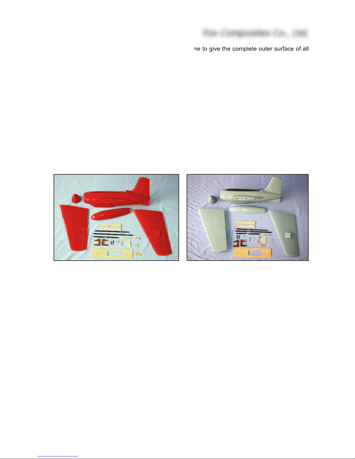
The Kit
Shown above are views of the complete kit contents as shipped, except for the CD-Rom that is
also included (with this Instruction Manual & additional photos). Currently kits are manufactured
in all-grey and all-red, but we may produce a ‘camouflage’ version later. A full list of kit contents,
including wood parts and hardware is included at the end of this manual.
The Komet is a full-ARF kit. The wings have been jig-aligned at the factory and fixings are completed. The elevon control surfaces and servo hatches are elastic-hinged and alreday cut out for
your convenience. All fuselage bulkheads, and the nose-ring, are factory-installed. Certainly it is
quite possible to complete the Komet assembly in about 10 hours.
The ‘ready-to-fly’ weight of an electric ‘Komet’ should be approx. 1kg (2.2Lbs), if built according to
these instructions, and using the recommended accessories and equipment. The total fibreglass
parts in the kit (fuselage, wings, nose, canopy & wing joiners) weigh approx. 450grams.
Fox Composites reserve the right to make changes to the kit for reasons of constant improvement, or production reasons, so it is possible that your moulded parts, milled wood parts or hardware might not look exactly as shown in the photos in this manual. Therefore, please check our
website for any instruction changes, or important updates, before commencing the assembly of
your ‘Komet’.
Fox Composites Co., Ltd.
4
Equipment and Accessories
In addition to the kit contents you will need some accessories, R/C, and small hardware items to
complete your ‘Komet’. Below are our recommendations, from experience with the prototypes.
Motor: The Komet has been designed primarily for electric flight, for a Speed-400 sized
motor of 400 - 700 watts. We used a Mega-motor 16/15/3 (400 watt) in the first prototype, which
gave more than adequate performance and ran very cool. Currently we are using a 700 watt Typhoon 2W-20 from Overlander Technologies, which gives amazing performance and easy handlaunches, even in zero-wind conditions. With both motors we’ve been using APC thin & Graupner
CAM electric propellers, both 4.75 x 4.75” size, and can recommend these. Larger props provide
too much load, and can lead to overheating of system components.
Speed-Controller (ESC): You will need a suitable speed-controller (with BEC circuit) that matches
your chosen electric motor and battery packs. Please follow the recommendations of the motor
supplier for the rating. For the 700 watt motor we have been using a ‘Castle Creations’ Phoenix
60 amp unit, which has been working very well indeed on both 3S1P and 4S1P Lipo packs.
The power package for this plane was developed in conjuction with Overlander Technologies in
the UK (www.overlander.co.uk). It is very important to have a well matched combination of motor,
ESC and batteries for good performance, without overheating any of the system components.
Flight batteries: Any good quality 3S1P or 4S1P Lipo pack of at least 2200mAH will be fine. Expect about 3.5 - 4.5 minute flights with a battery of this capacity. We are currently using Kokam
2200 (3S) and 3200 (4S) packs.
Servos: You will need 2 ‘thin’ digital wing servos for the elevons, of minimum 3.5kg torque,
such as the JR DS161 or Hitec HS-5125 MG, and the servo mounts are milled to suit these. If you
fit the optional rudder, then any mini servo of min. 2.5kg torque should be sufficient.
About the Me-163 ‘Komet’
The Fox Composites ‘Komet’ was designed as a semi-scale electric ‘fun-fly’ model. Normally the
model is hand-launched, but you could also use a very short bungee system if you fly on your
own. Performance is sparkling with a 700 watt motor, with shallow dive speeds of over 130 mph
(200 kph), and you have to be careful to keep it within eyesight range. It is fully aerobatic and will
perform all the usual manoeuvres that a tail-less plane is capable of, and it has great gliding characteristics. If you chose to fit the (optional) rudder you will be surprised at the excellent knife-edge
flight, which has no roll-coupling at all. Landing is also easy as it is very docile at slow speeds.
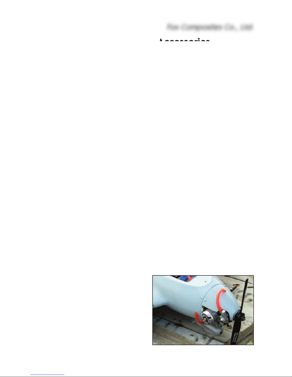
During testing of the 3 prototype models we experimented with the fitting of a small .15 glow
motor (Thunder Tigre .15), but the results were
rather disappointing ! It was much more work to
build, slightly heavier, noisy, dirty ... and did not
have the performance and ‘fun-factor’ of the electric versions. However we have included a couple
of photos of the glow motor installation, and a fibreglass fairing for the muffler is available as an
option, for anyone that wants to fit a small 2stroke motor.
Fox Composites Co., Ltd.
5
Building Instructions
The Komet is very quick and simple to build, but we recommend that you complete the fuselage
before the wings, as the front wing dowels and front wing joiner also hold the battery and R/C tray
into position in the fuselage - which means you need to complete this to fit your chosen Lipo flight
packs first.
Fuselage:
The lightweight fuselage is a fibreglass and epoxy moulding, with a vacuumed foam-sandwich
vertical fin, painted in the moulds in a single colour.
The 3 main bulkheads are made from a 6mm foam and glass sandwich, which is extremely lightweight, and these are factory installed for you. Their purpose is to maintain the fuselage shape and
support the battery tray. We have also installed the balsa/fibreglass composite root ribs, the 3mm
balsa/fibreglass composite ring bulkhead in the nose area, and the 5mm thick fin bulkhead/spar.
Motor installation
The motor is secured to the fibreglass
ring mount supplied, with small bolts,
and the complete assembly is glued
into the nose cone, which is finally
glued onto the fuselage permanently.
Tip: You can wait to glue the nose
cone on until the rest of the fuselage
is finished, which gives easier access
when installing the battery tray, etc,.
It is important to set a little right-thrust
(about 2 degrees) into the motor
when gluing the mounting ring into
the nose. Therefore you must offset
the motor about 1.5mm to the (pilots)
left when bolting it into the fibreglass
ring - so that the propeller is still centred on the fuselage when installed.
Drill the fibreglass mounting ring to
suit the mounting holes of your motor
(1.5mm offset to the left), and cut out
the cooling slots for the motor also.
Bolt the motor to the mount, and
chamfer the outside edge a little to fit
the tapered shape of the nose cone.
Sand the inside surface of the fibreglass nose cone with 120 grit and
clean off the dust. Cut the circular
hole in the front of the nose cone for
cooling, which also allows you to access the mounting bolts. This will
Fox Composites Co., Ltd.
6
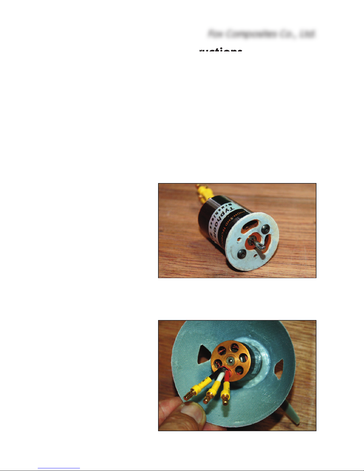
(above) Typhoon 2W-20 bolted to the fibreglass motor
mount, with cooling slots cut out.
(below) Motor mount glued into nose cone, about
1.5mm offset to allow for the necessary right-thrust.
 Loading...