

Fox Composites F-86 Sabre Instruction Manual
Fox Composites Co., Ltd.
January 2008 version: 1.0
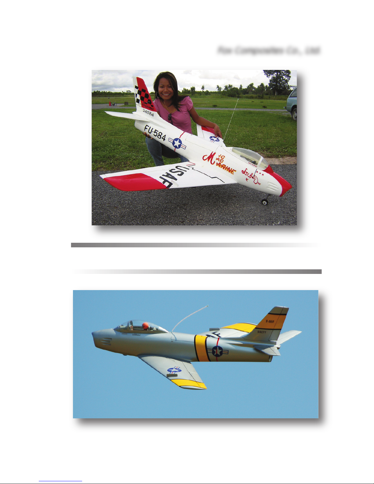
Fox Composites F-86 Sabre

Instruction Manual for F-86 Sabre model airplane kit
Thank you for purchasing the F-86 Sabre kit (55.5" span) manufactured by Fox Composites.
These instructions are available as a full-colour free down-loadable Adobe Acrobat .pdf file on our
website (www.fox-composites.com), and also on a CD-Rom in every kit box. In addition, we have
included high resolution versions of all the photos used in the Manual, and some extra photos
showing detailed construction areas, on the CD for your assistance.
We strongly advise that you read this Instruction Manual completely, and make sure you understand all of it, before commencing assembly of the Sabre kit.
Please remember that our Sabre kit is based on the original hand-made plugs from the ductedfan version flown since 1983 and, although fully re-engineered for the new full-composite 'turbine'
version, we are aware that it is not perfectly symmetrical in a few areas. However, these small
discrepancies have no affect on the accurate and docile flying characteristics of the plane.
We hope you have much enjoyment and many safe flights with your F-86, and always welcome
feedback from Customers, and photos of your completed plane. If you have any technical questions about this product, or require spare parts, please contact us at:
email: jim@fox-composites.com alternative email: jimjet45@gmail.com
website: http://www.fox-composites.com
address: Fox Composites Co., Ltd. 19/88 Moo 5. Soi 53, Nongprue. Banglamung.
Pattaya. Chonburi 20150. Thailand.
Liability Exclusion
You have acquired a kit which can be assembled into a fully working and flying radio-controlled
model airplane when properly fitted with suitable equipment and accessories, and constructed according to the current instructions provided by Fox Composites Co., Ltd. for the kit.
However, as the manufacturers of this kit, Fox Composites Co,. Ltd cannot influence the manner
in which the model is built, fitted out and operated, and we are unable to control the methods and
equipment you use to install, operate and maintain the radio control system components. Therefore we are obliged to deny all responsibility and liability for any direct, or consequential, injury, loss,
damage or costs involved due to the incorrect or incompetent assembly, use or operation of this
product, or any circumstances connected with it. When operating this product you must assume
all responsibility for any resulting consequences.
Unless otherwise determined by binding law, Fox Composites Co,. Ltd. are excluded from paying
any compensation with regard to operation of our products. The maximum liability of Fox Composites Co., Ltd with regard to this product is limited to the amount that you actually paid for the
kit in all circumstances.
Fox Composites Co.,Ltd are unable to monitor whether you follow our instructions with regard to
assembly, operation & maintenance of the model airplane. Therefore we are not able to guarantee or provide any contractual agreement with the operator or owner of the product that it will function correctly and safely. The operator of the product must rely on their own judgement in obtaining,
constructing and operating this model airplane.
Fox Composites Co., Ltd.
1
Safety
All model airplanes can provide a potential hazard for personal injury or damage to property if not
operated with care, and assembled and used in accordance with the instructions of the manufacturers of all the parts contained within it. It is your responsibility to operate and fly your Sabre in
accordance with all current laws & regulations governing model flying in the country of operation.
Before the first engine run, make sure that the motor, control surfaces, R/C gear and all servos with
their associated linkages are all attached securely. Double-check that heavy items, like batteries,
are attached very securely in the plane and cannot move at all.
Make absolutely sure that the Centre of Gravity is in the position shown at the end of this manual.
Carry out a proper range check with your R/C system, in both motor 'running' and motor 'off' states,
and ensure that the range achieved before fail-safe occurs is at least in accordance with the R/C
manufacturers minimum recommendations.
When starting and running the motor on the ground, make sure that the plane is firmly secured so
that it cannot move and ensure that all spectators are at least 15 metres behind or to the sides, or
far in front of the plane.
Adhesives
Gluing composite parts together does not require any special types of glue, but due to the high
flight speeds attainable with a jet model it is absolutely necessary to use high quality adhesives
and proper gluing techniques to ensure airframe integrity, and therefore safety.
For a strong glue joint it is equally important to use high-quality glue
and to prepare both parts to be joined properly. When joining any combination of fibreglass and wood parts together you must lightly sand
both parts (to provide a mechanical 'key' for the glue) and clean off
the dust caused by sanding before joining them. You can use many
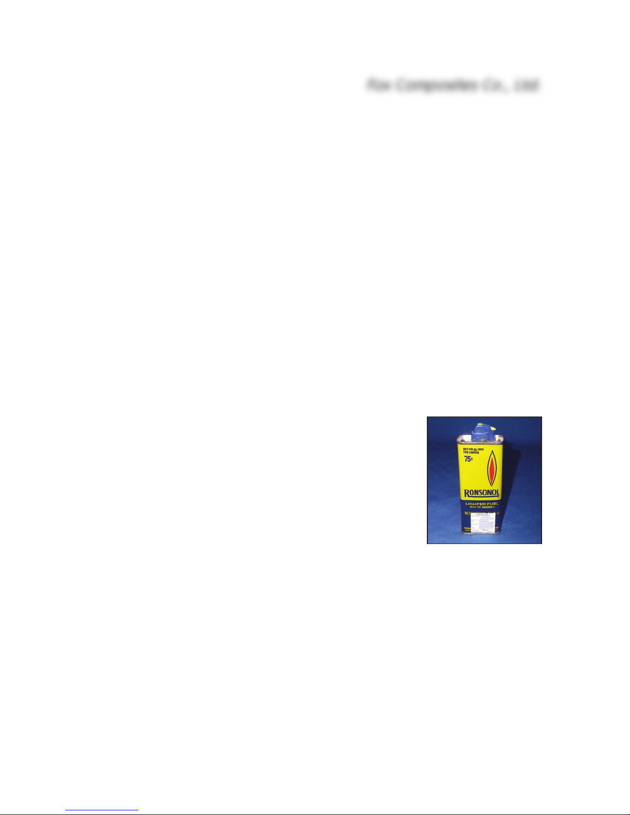
cleaning agents for this, however many of them will damage the 2pack polyurethane paint used to colour the parts in the mold. Therefore we highly recommend that you use de-natured alcohol or common
lighter-fluid, such as 'Ronsonol'. This is what we use at the factory,
and it can also be used to wipe uncured glue off painted surfaces, without damaging the paint.
When sanding the inside surface of the foam vacuum-sandwich parts (eg: wings, fins and stabilisers) be careful not to sand right thru' the lightweight glasscloth, as this will reduce the rigidity
of the parts. Only a light sanding with 120 - 240 grit is necessary, followed by cleaning.
The fuselage is a fibreglass and epoxy moulding, without a foam sandwich, and we strongly suggest that you sand the complete inside surface of it before starting any assembly - using 120 or
180 grit, or red Scotchbrite pad. This will also remove any loose glass strands that might otherwise
get into your hands! It is especially wise to sand very carefully inside the whole nose section of
the fuselage, as access is limited after the nosegear bay and inlet duct are glued in place.
At Fox Composites we only use 1st quality slow (24hr) laminating epoxy mixed with micro-balloons, ZAP 30 minute epoxy (mixed with micro-balloons), ZAP CA glues and Hysol 9462 thixotropic
epoxy for assembly and important joints, and can highly recommend these types. Micro-balloons
are added to all epoxy mixtures to increase the gap-filling ability, without adding weight. Milled
Fox Composites Co., Ltd.
2

fibre is added to epoxy to increase the strength of the adhesive. Do not use any polyester-based
glues under any circumstances.
Before starting assembly of your Sabre it is also wise to give the complete outer surface of all the
parts at least 2 coats of clear car wax (not the silicone based type) wiped on with a soft cloth. This
usually makes is possible to remove any accidental small spots of glue or finger marks that get on
there during building. Of course you must make sure to remove this wax completely before doing
any painting or adding trim and markings/decals to your model at the finishing stage. Fortunately
the wax is easy to remove using 'Ronsonol' lighter fluid, or equivalent.
Take Care
The vacuum-cured foam sandwich construction used for the flying surfaces gives a very lightweight, but torsionally stiff and strong structure. However it is relatively easy to 'dent' the outer
surface, and so it is necessary to protect the model during assembly by covering your workbench
with soft carpet or foam. Included in the kit are protective foam bags for the complete fuselage,
wings, vertical fin and horizontal stabs - and these should always be used during storage and
transport to protect your plane.
Included in the Kit
Shown above is a view of the complete kit contents as shipped, except for the CD-Rom that is also
included (with this Instruction manual and additional photos). A full list of kit contents, including
wood parts and hardware is included at the end of this manual.
The wing, horizontal stabiliser and vertical fin are all jig-aligned at the factory and fixings are completed - and it is possible to assemble the main parts of the model within 10 minutes or so. All
control surfaces are now elastic-hinged for your convenience.
Fox Composites reserve the right to make changes to the kit for reasons of constant improvement, or production reasons, so it is possible that your moulded parts or hardware might not look
exactly as shown in the photos in this manual. Therefore, please check our website for any instruction changes, or important updates, before commencing assembly of your F-86 Sabre.
Fox Composites Co., Ltd.
3

Equipment and Accessories
In addition to the kit contents you will need some accessories, R/C, additional equipment and
small hardware items to complete your Sabre. The list below can act as a 'Check-list' to remind
you of the main items that will be needed, and our recommendations - based on our own experience, and that of several respected customers who have been operating our Sabre successfully.
Turbine: (4.5 - 6.5kg thrust) and installation kit with ECU, mounting strap, fuel pump and so-
lenoid valves etc. (eg: Wren MW44, MW54, PST600, Jetcat P60). This model is designed to operate with turbines up to a maximum of 6.5kg (14lbs) thrust, and the fitting of a more powerful
turbine could cause excessive speed and structural failure, and consequentially injury or damage
to persons or property. No reference is made to EDF units in these instructions, but we know that
some customers have successfully flown our Sabre with Electric Ducted-Fan units.
Thrust Tube: You will need to supply a suitable thrust tube for your turbine. A good source of
lightweight, well-designed, thrust tubes is Wren Turbines (UK). (www.wren-turbines.com)
Retracts: The kit was designed around Spring-Air 300 (or 700) series main gears (90 de-
gree) and Spring-Air 300 (100 degree) nose gear but, of course, many other units of a similar size
can be used. The main gear units cannot be higher than 30mm if you want the legs to fit fully into
the wings. A 100 degree retracting nosegear also allows the wheel to fully retract into the fuselage,
and retain the slight forward rake on the extended leg for a more scale-like appearance.
Wheels: We used a Ø 45mm nosewheel (1.75"). A soft foam type helps to prevent bounc-
ing during landing. Main wheels should be Ø 56 - 60mm (2.25 - 2.5"), and as thin as possible to
fit completely flush in the wing. The Robart type shown in the photos is Ø 66mm (2.75") and a little too thick to fit totally flush.
Servos: For ease of installation we highly recommend that you use 4 'wing' servos such as
the 15mm thick digital JR3301 or Graupner 3328 for flaps and ailerons, as they have integrated
side-mounts on the servo case. In any case you should use digital types with a minimum torque
of 4kg. The horizontal stabiliser is quite thin, and therefore we recommend a pair of the 10.5mm
thick digital JR DS161's for the elevators. An alternative is the Hitech HS-5125 which is identical
in size, and has metal gears. Any mini-servo of minimum 4kg and 15mm thickness (eg: JR 3301,
3401 or Graupner 3328) will fit easily inside the vertical Fin for rudder control. A 'standard-sized'
servo easily fits in the nosegear bay for nose steering, preferably with metal output gear. Retract
valves, etc., can normally use any mini servos of at least 2kg torque.
Fuel System: A pair of fibreglass moulded main tanks (approx. 800cc each) are included in the
kit, which fit into bays in the wings. The tanks have an internal baffle installed during manufacture,
to prevent fuel surge. Included is basic stopper hardware, but you need to provide the brass tubing (1/8" O.D), kerosene stoppers (Dubro part #400), clunks and I.D 3 - 3.5mm Tygon tube. If fitting a turbine at the higher end of the thrust range you can fit an additional tank of about 300cc
(10 fl.oz) in the fuselage, just in front of, and below, the turbine.
We recommend a small 'hopper' tank between the main tanks and fuel pump, to prevent air bubbles getting to the turbine that could cause a 'flame-out'. Suitable tanks can easily be made from
any small 3 - 4oz tank, or you could use a BVM UAT, or the excellent small 'air-trap' from Intairco.
In addition you will need kerosene-proof fuel tube to suit your turbine, fuel filters etc.
Batteries/Switches: The Sabre has a tendency to be slightly tail-heavy if fitted with a turbine at
Fox Composites Co., Ltd.
4
the upper end of the thrust range, and all the batteries will normally be fitted in the nose. Using a
5 or 6-cell ECU/pump battery (sub C NiCad cells) and two 5 cell 800 mA (AA sized) NiMH receiver
packs no additional weight was needed in the nose of the factory PST 600 powered Sabre. Depending on the recommendations of your R/C manufacturer, be sure to use a voltage regulator to
limit the max. current to your receiver ! One simple way to achieve this is to use the excellent
(small & lightweight) Powerbox 'Sensor' switch which combines dual electronic 'fail-ON' switches
for dual Rx batteries, with dual inputs and outputs, and an integral 5.9v voltage regulator.
Building Instructions
There is no special sequence necessary for construction of the Sabre, and you can work on several areas at the same time if you wish, making it a very quick plane to build. However it is easiest to follow the sequence shown below for the the fuselage assembly, for ease of access.
It is wise to complete the rudder and elevator servos, and finish the wing servos and main
gear/wheels before commencing on the fuselage R/C and motor installation so that you can gauge
any CG problems you might have later, which might only occur if using a turbine at the higher end
of the recommended thrust range, or a very heavy exhaust duct/thrust tube. If using the recommended landing gear and servos and a smaller motor (eg: Wren MW44) you should have no problems in obtaining the correct CG without adding any additional weight in the nose at all.
Horizontal Stabiliser and Elevators:
The stabiliser is laminated from a lightweight fibreglass and foam sandwich (about 2mm thick),
cured under vacuum, and painted in the molds in a single colour. The one-piece stab has been factory-fitted onto your fuselage, and aligned with the wing in a jig, thereby also setting the correct
incidence. The upper fairing and stab fixings have also been completed, and glued into position
in the jig. The front of the stab is secured with a plywood tab into bulkhead in the fuselage, and
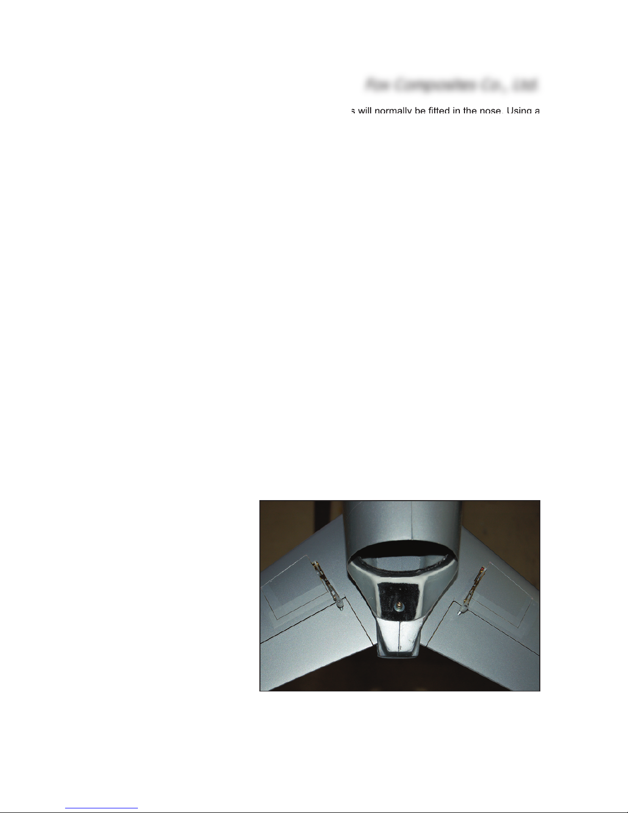
the back is held in position with an M4 x 25mm bolt, and washer, that is inserted from underneath
and passes through the stab into a factory-installed M4 T-nut inside the upper stab fairing.
The elevators are elastichinged in the mould. All you
need to do is install servos, elevator control horns & linkages.
The hatches for the servos are
pre-cut for you, and elastic
hinged at the front. The stab is
only about 12mm thick at the
outer edge of the servo pockets, so you will need to use
very slim servos such as the
recommended JR DS 161's
shown here (10.5mm thick).
You will need to use 2 receiver
channels to control the elevators (if fitted as shown), unless
Fox Composites Co., Ltd.
5
Completed stabiliser, hatches taped closed, and servo linkages, viewed from below. Also shows stab fixing bolt.
you have fitted both servos with
the same orientation. In that
case you will need to purchase
either 1 'reversed' servo - or
use an electronic reverser on
one servo (eg: JR Match-box).
The added advantage of using
a 'Match-box' is that it allows
you to separately set the neutral points & end-points of up to
4 servos on a single Rx channel servo to match each other.
Decide on the orientation of
your servos, and trial fit the 'Ushaped' milled lite-plywood
mounts, which are sized to suit
the DS161's (and the Hitec
#HS-5125MG). The wider part
fits towards the leading edge of
the stab, and the back of the
mount will be glued against the
rear spar in the stab. Remove
the mounts. Centre the servos
using your Transmitter, fit the
servo arms at 90° to the servo
case, set the travels to 125%
(or maximum) and screw the
servos onto the mounts. Sand
the bottom surface of the
mounts and the inside of the
stab skins in the servo pockets
carefully for a good glue bond.
Do not glue them in place yet!
Mark the position against the
inner edge of the hatches
where the servo arms will be,
and file slots in the skin for
them as shown. Now you can glue in the mounts into the stab, with the servos in place and the
servo arms exactly perpendicular to the leading edge of the elevators. Use a 30 minute epoxy and
micro-balloons mixture, and make sure that they are properly glued to the rear balsa/glass spar
in the stab. When the glue has cured, remove the servos and add glue to any parts that are not
properly bonded, making sure that they are well fixed to the rear balsa spar in the stab.
Tape the elevators into the neutral position. Carefully mark the line (on masking tape) of the linkage, exactly in line with the servo arms. The control horns are made from the 35mm lengths of M3
threaded rod included in hardware. There are small plywood blocks installed in the elevators for
the horns during manufacture. Drill right thru' the elevator on the marked line, exactly 10mm behind the front edge of the elevator, using a sharp Ø 2.2 or 2.3mm drill. Use a 90° square to keep
the drill perpendicular to the bottom surface of the elevators. The holes should be just behind, or
against, the balsa elevator spars.
Fox Composites Co., Ltd.
6
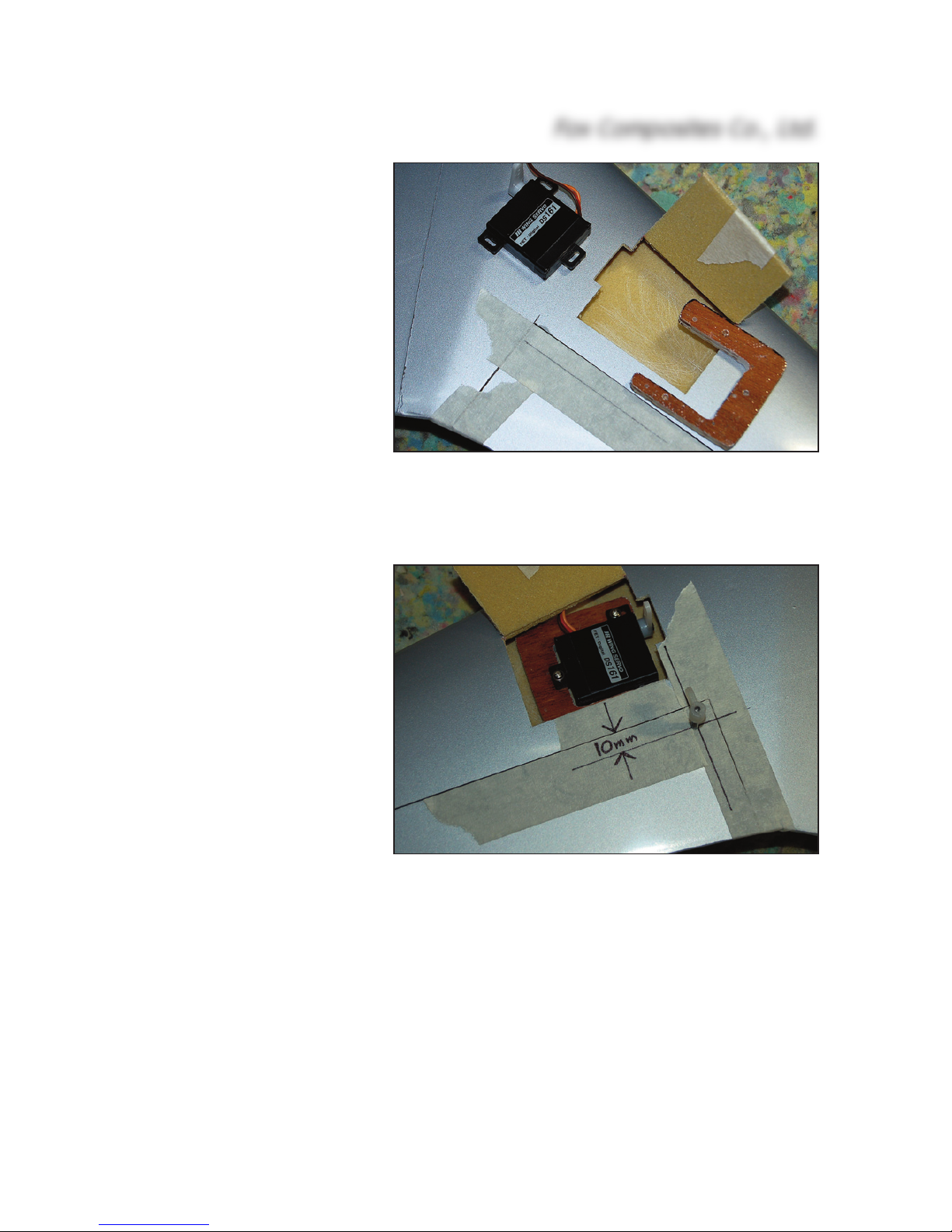
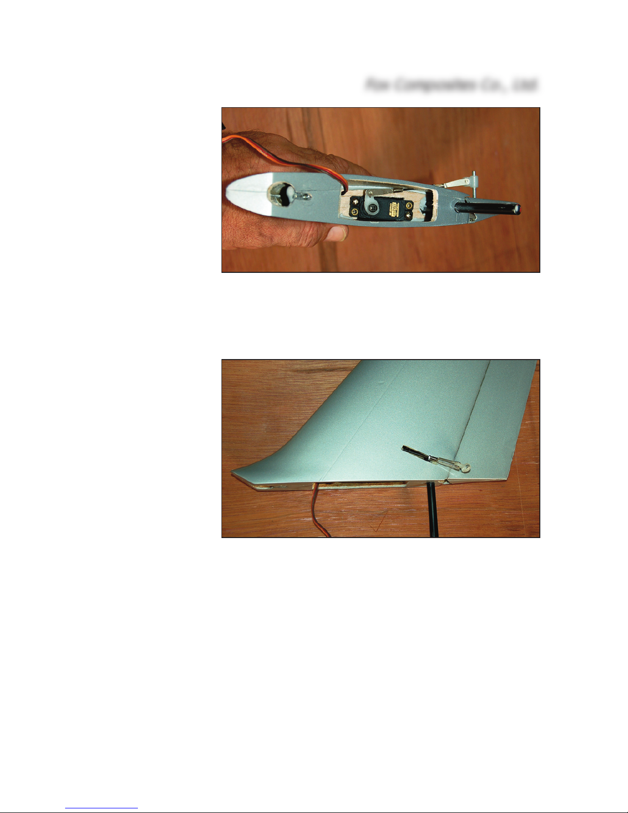
(above) Digital DS161 servos are installed in the milled ply
mounts supplied in the kit. Cut slot as shown for servo arm.
(below) The elevator horn must be installed in line with
the servo arm, and 10mm behind the leading edge of elevator. Drill Ø 2.2mm, and tap M3 for the M3 threaded rod.
Now thread these holes, right
thru' the elevators, using an M3
tap. Sand both ends of the
threaded rods flat, and screw
on the plastic adapters provided. Screw them into the
tapped holes until the upper
end is flush with the top surface
of the elevators. The M3 rods
must now be secured in place,
by applying glue through the
open (root) end of the elevators. Apply one drop of thick CA
and, when cured, add some 30
minute epoxy and micro-balloons mixture.
Make up the linkages between the servo and elevator horns, using M2 or 2 x 56 clevises and
threaded rods. The linkages will need to be approx. 45mm long, clevise pin-to-pin. Fit the clevise
on the servo arm as close to the servo centre as possible, and the clevise on the elevator horn as
far out from the elevator as possible - to maximise the mechanical advantage, whilst still obtaining the necessary maximum elevator throws of 10 - 11mm up and down. When the linkages are
finally adjusted the servo hatches can be held closed with 3 small strips of clear tape. It is not necessary to secure them with screws. Some small scraps of very thin ply or fibreglass sheet glued
inside the edges of the servo bays keep the hatches flush with the wing skin.
IMPORTANT: Do NOT use ball-joints or ball-links on the plastic horn adapters. They will cause
twisting, and almost certain flutter ! This also applies to the aileron and rudder linkages.
The servo extension cables should be passed thru' 2 separate small holes drilled in the bottom surface of the centre-section, as close to the fuselage sides as possible to keep them away from the
thrust-tube, and protected with small plastic grommets. As the servo cables are quite close to the
(hot) thrust-tube in the fuselage we strongly recommend that you additionally protect them by
wrapping the cables with self-adhesive aluminium tape and fixing them securely to the sides of the
fuselage - as far away from the thrust-tube as possible. This also applies to the servo extension
cable for the rudder servo.
Fin and Rudder:
The vertical fin and elastic-hinged rudder is laminated
from a lightweight fibreglass and foam sandwich, cured
under vacuum, and painted in the molds in a single
colour. It has been fitted to your stabiliser assembly at
the factory, and vertical alignment is already set. Small
directional adjustments can be made when installing
the retaining bolt at the front.
The fin is held onto the stab with a single Ø 7mm fibreglass spar rod, and is secured using an M4 bolt and Tnut at the front. The 6mm thick lite-ply servo mount is
already installed, but you may have to enlarge the
Fox Composites Co., Ltd.
7
milled slot to suit your
servo. Shown installed
here is a digital
JR3401 servo.
Centre the servo with
your Tx, set the travels
to maximum, and fix a
short servo arm onto it
at 90° to the servo
case as shown. Screw
the servo into place,
with the output shaft
towards the leading
edge of the Fin.
Route the extension
cable upward and forward, thru' the milled
hole in the front balsa
spar, and then down
and out of the bottom
of the fin. Apply some
masking tape to the
outside of the fin (left
side) and carefully
mark the position of
the servo arm centreline on it. Extend this
line onto the rudder,
exactly perpendicular
to the leading edge.
Drill a Ø 2.2mm hole
right thru the rudder,
on this line, 10mm
from the leading edge
and tap M3 for the
control horn in the same way as for the elevators and ailerons. Screw the M3 threaded rod into
the threaded hole, and secure with a drop of 30 minute epoxy and microballoons through an 8mm
hole drilled in the bottom of the rudder. Make up the linkage as shown, using your choice of hardware (M2 or 2 x 56 UNC). Cut a small slot in the outer skin of the rudder, as shown, and lengthen
the slot until you can fit the linkage as shown and obtain throws of 15mm both sides.
The fin is secured to the fuselage with a M4 x 25 bolt at the front, that screws into an M4 T-nut that
has been fitted into the fin already. The hole has been drilled in the fuselage for the bolt, but can
be adjusted if necessary. Cut a small reinforcing plate of 3mm plywood, 20 x 30mm, and drill a
4mm hole in the centre of it. Wax the M4 bolt thread. Pass the M4 bolt thru’ the hole and screw it
up into the stab from inside the fuselage. Make any small adjustments to the Fin position now, so
that it is straight with the fuselage centreline. Glue the plywood reinforcing plate to the inside of
the fuselage with 30 min. epoxy and micro. Secure the rudder servo extension cable to the side
of the fuselage and make sure that it cannot come into contact with the hot thrust tube.
Fox Composites Co., Ltd.
8
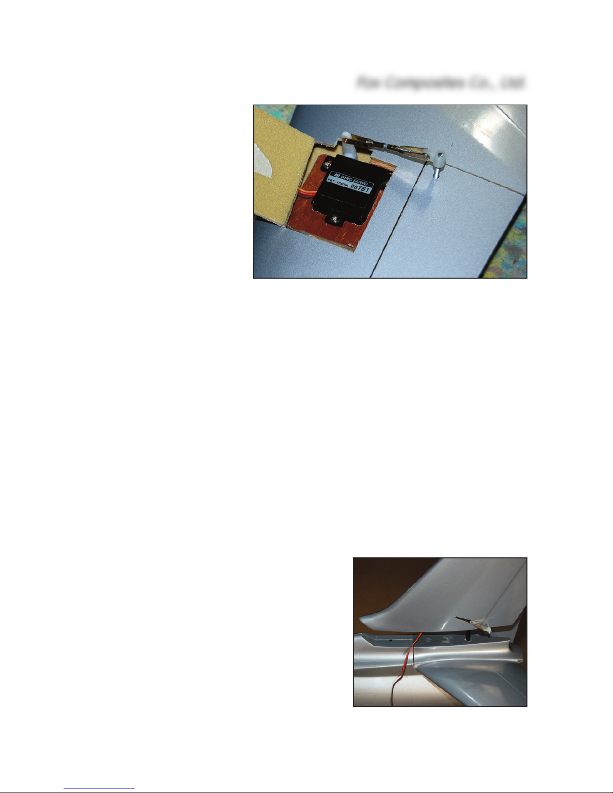
(above) Rudder is controlled by min. 4kg mini-servo servo screwed
to factory-installed plywood mount. Use a short servo arm and adjust
control horn to give 13 - 15mm throw each way.
(below) Fin is secured to the stabiliser with Ø7mm spar rod that fits
into a fibreglass tube, and an M4 bolt at the front into a T-nut in the
base of the fin - all factory-finished for you.
 Loading...