

Fox Composites BAe Hawk User Manual
Fox Composites Co., Ltd.
April 2008 version: 1
Fox Composites BAe Hawk

Instruction Manual for BAe Hawk model airplane kit
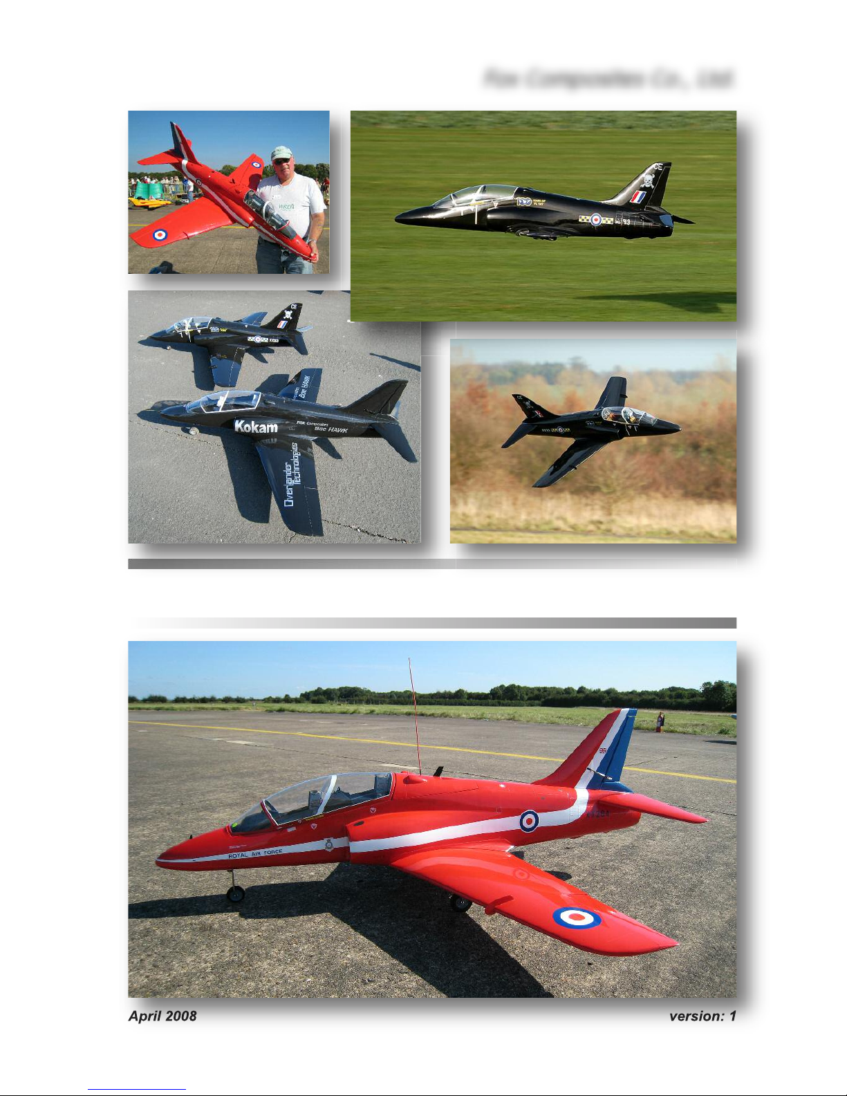
Thank you for purchasing the BAE Hawk kit (58"/147cm span) manufactured by Fox Composites.
These instructions are available as a full-colour freely down-loadable Adobe Acrobat .pdf file from
our website (www.fox-composites.com), and also on a CD-Rom in every kit box. In addition, we
have included high resolution versions of all the photos used in the Manual, and some extra photos showing detailed construction areas, on the CD for your assistance.
We strongly advise that you read this Instruction Manual completely, and make sure you understand all of it, before commencing assembly of the Hawk kit.
Please remember that our Hawk kit is based on the original hand-made plugs from the ducted-fan
version flown since 1983 and, although fully re-engineered for the new full-composite 'turbine' version, we are aware that it is not perfectly symmetrical in a few areas. However, these small discrepancies have no affect on the accurate and docile flying characteristics of the plane.
We hope you have much enjoyment and many safe flights with your Hawk, and always welcome
feedback from Customers, and photos of your completed plane. If you have any technical questions about this product, or require spare parts, please contact us at:
email: jim@fox-composites.com alternative email: jimjet45@gmail.com
website: http://www.fox-composites.com
address: Fox Composites Co., Ltd. 19/88 Moo 5. Soi 53, Nongprue. Banglamung.
Pattaya. Chonburi 20150. Thailand.
Liability Exclusion
You have acquired a kit which can be assembled into a fully working and flying radio-controlled
model airplane when properly fitted with suitable equipment and accessories, and constructed according to the current instructions provided by Fox Composites Co., Ltd. for the kit.
However, as the manufacturers of this kit, Fox Composites Co,. Ltd cannot influence the manner
in which the model is built, fitted out and operated, and we are unable to control the methods and
equipment you use to install, operate and maintain the radio control system components. Therefore we are obliged to deny all responsibility and liability for any direct, or consequential, injury, loss,
damage or costs involved due to the incorrect or incompetent assembly, use or operation of this
product, or any circumstances connected with it. When operating this product you must assume
all responsibility for any resulting consequences.
Unless otherwise determined by binding law, Fox Composites Co,. Ltd. are excluded from paying
any compensation with regard to operation of our products. The maximum liability of Fox Composites Co., Ltd with regard to this product is limited to the amount that you actually paid for the
kit in all circumstances.
Fox Composites Co.,Ltd are unable to monitor whether you follow our instructions with regard to
assembly, operation & maintenance of the model airplane. Therefore we are not able to guarantee or provide any contractual agreement with the operator or owner of the product that it will function correctly and safely. The operator of the product must rely on their own judgement in obtaining,
constructing and operating this model airplane.
Fox Composites Co., Ltd.
1
Safety
All model airplanes can provide a potential hazard for personal injury or damage to property if not
operated with care, and assembled and used in accordance with the instructions of the manufacturers of all the parts contained within it. It is your responsibility to operate and fly your Hawk in
accordance with all current laws & regulations governing model flying in the country of operation.
Before the first engine run, make sure that the motor, control surfaces, R/C gear and all servos with
their associated linkages are all attached securely. Double-check that heavy items, like batteries,
are attached very securely in the plane and cannot move at all.
Make absolutely sure that the Centre of Gravity is in the position shown at the end of this manual.
Carry out a proper range check with your R/C system, in both motor 'running' and motor 'off' states,
and ensure that the range achieved before fail-safe occurs is at least in accordance with the R/C
manufacturers minimum recommendations.
When starting and running the motor on the ground, make sure that the plane is firmly secured so
that it cannot move and ensure that all spectators are at least 15 metres behind or to the sides, or
far in front of the plane.
Adhesives
Gluing composite parts together does not require any special types of glue, but due to the high
flight speeds attainable with a jet model it is absolutely necessary to use high quality adhesives
and proper gluing techniques to ensure airframe integrity, and therefore increased safety.
For a strong glue joint it is equally important to use high-quality glue
and to prepare both parts to be joined properly. When joining any combination of fibreglass and wood parts together you must lightly sand
both parts (to provide a mechanical 'key' for the glue) and clean off
the dust caused by sanding before joining them. You can use many
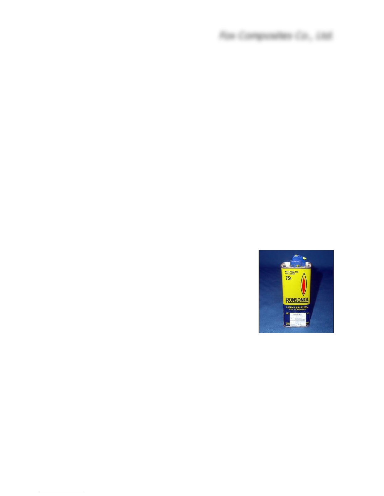
cleaning agents for this, however some of them may damage the 2pack polyurethane paint used to colour the parts in the mold. Therelighter-fluid, such as 'Ronsonol'. This is what we use at the factory,
and it can also be used to wipe uncured glue off painted surfaces, without damaging the paint.
When sanding the inside surface of the foam vacuum-sandwich parts (eg: wings, fins and stabilisers) don’t sand right thru' the lightweight glasscloth on the inner surface, as this will reduce the
rigidity of the parts. Only a light sanding with 120 - 240 grit is necessary, followed by cleaning.
Be careful if using thin CA on foam sandwich components, as it can soak into the foam and expand as it cures and heats up - causing a blemish (bump) on the outer skin. The use of Activator
(‘Kicker’) increases the chance of this even more!
The fuselage is a fibreglass and epoxy moulding, without a foam sandwich, and we strongly suggest that you sand the complete inside surface of it before starting any assembly - using 180 or
240 grit, or red Scotchbrite pad. This will also remove any loose glass strands that might otherwise
get into your hands! At Fox Composites we only use 1st quality slow (24hr) laminating epoxy
mixed with micro-balloons, ZAP 30 minute epoxy (mixed with micro-balloons) and Hysol 9462
thixotropic epoxy for assembly and important joints, and can highly recommend these types. Microballoons are added to all epoxy mixtures to increase the gap-filling ability, without adding weight.
Fox Composites Co., Ltd.
2
M
illed fibre is added to epoxy to increase the strength of the adhesive. Do not use any polyester-
b
ased glues under any circumstances, as they will not bond properly to the epoxy parts.
Before starting assembly it is also wise to give the complete outer surface of all the parts at least
2 coats of clear car wax (not silicone-based as very difficult to completely remove) wiped on with
a soft cloth. This usually makes it possible to remove any accidental small spots of glue or finger
marks that get on there during building. Of course you must make sure to remove this wax completely before doing any painting or adding trim and markings/decals to your model at the finishing stage. Fortunately the wax is easy to remove using 'Ronsonol' lighter fluid, or equivalent.
Take Care
The vacuum-cured foam sandwich construction used for the flying surfaces gives a very lightweight, but torsionally stiff and strong structure. However it is relatively easy to 'dent' the outer
surface, and so it is necessary to protect the model during assembly by covering your workbench
with soft carpet or foam. Included in the kit are protective foam bags for the complete fuselage,
wings, vertical fin and horizontal stabs - and these should always be used during storage and
transport to protect your plane.
Included in the Kit
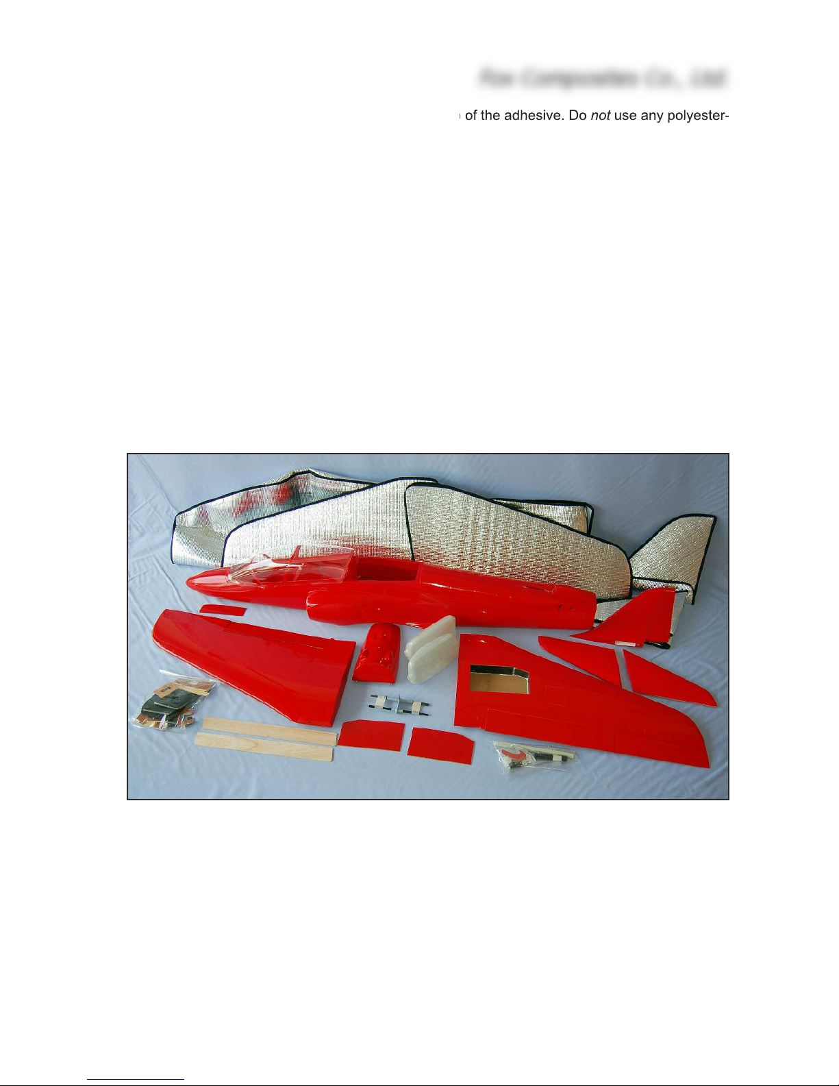
Shown above is a view of the complete (turbine) kit contents as shipped, except for the CD-Rom
that is also included, with this Instruction manual & additional photos. A full list of kit contents, including wood parts and hardware is included at the end of this manual.
‘Turbine’ and ‘Electric ducted-fan’ kit versions are available, and the differences between the kit
contents are shown at the end of this manual, which describes the assembly of the turbine version. All control surfaces are now elastic-hinged for your convenience.
Fox Composites reserve the right to make changes to the kit for reasons of improvement, or production reasons, so it is possible that your moulded parts or hardware might not look exactly as
Fox Composites Co., Ltd.
3

s
hown in the photos in this manual. Therefore, please check our website for any instruction
c
hanges, or important updates, before commencing assembly of your Hawk.
Equipment and Accessories
In addition to the kit contents you will need some accessories, R/C, additional equipment and
hardware items to complete your Hawk. The list below can act as a 'Check-list' to remind you of
the main items that will be needed, and our recommendations - based on our own experience, and
that of several respected customers who have been operating our Hawk successfully.
Turbine: (4.5 - 7kg thrust) and installation kit with ECU, mounting strap, fuel pump and so-
lenoid valves etc. (eg: Wren MW44, MW54, PST600, Jetcat P60). This model is designed to operate with turbines up to a maximum of 7kg (16lbs) thrust, and the fitting of a more powerful turbine
could cause excessive speed and structural failure, and consequentially injury or damage to persons or property.
EDF: The fitting of Electric Ducted Fan units is not described in these instructions, as
there are so currently many different systems being tried, but there is a good building thread about
both the turbine and electric versions (by Paul Gray) on the internet at RCUniverse at: www.rcuniverse.com/forum/m_5453789/mpage_1/key /tm.htm or just search for “Fox Composites”.
Thrust Tube: You will need to supply a suitable thrust tube for your turbine. A good source of
lightweight, well-designed, thrust tubes is Wren Turbines (www.wren-turbines.com). An alternative is PST Jets (www.pstjets.com) and their thrust tube is shown in this manual.
Retracts: The kit was designed around Spring-Air 300 (or 700) series main gears (90 de-
gree) and Spring-Air 100 or 300 series (90 or 100 degree) nose gear but, of course, many other
units of a similar size can be used. Main landing gear units of up to 35mm height can be installed,
with the wire leg and wheel still fitting inside, or flush, with the bottom wing surface. A 100 or 105
degree retracting nosegear (firewall style) also allows you to fit the ‘scale’ forward-retracting noseleg, but it is far easier to fit a 90 degree rearward-retracting unit, as described below.
Wheels: We used a Ø 50mm nosewheel (2"). A soft foam type helps to prevent bouncing
during landing. Main wheels should be Ø 56 - 67mm (2.5 - 2.75"). The Robart type main wheel
shown in the photos is Ø 67mm.
Servos: For the ailerons we recommend that you use 'wing-servos’, with integral side-
mounts - such as the (10.5mm thick) JR DS161 or Hitech 5125MG, or the (15mm thick) JR DS3301 or Graupner DS-3328, due to the limited space inside the wing. In any case you should use
digital types with a minimum torque of 4kg.
The flaps are large surfaces on the Hawk, and therefore we highly recommend using standard
sized servos, with a minimum of 5kg torque. Many servos will be adequate for these - for example the digital JR/Graupner 5391, 8231 or 8311 shown here.
The horizontal stabilisers are controlled by a single servo mounted in the fuselage, and this should
be a standard sized digital servo with at least 8kg torque. (eg: JR DS8311, DS8411). Fitting the
highest quality unit possible here will reward you with a responsive plane with good centering.
Any mini-servo of minimum 3kg and 15mm thickness (eg: JR 3301, 3401 or Graupner 3328) will
fit easily inside the vertical Fin for rudder control. We recommend a standard sized servo for
Fox Composites Co., Ltd.
4

n
osegear steering, as the larger gears (preferably metal) can handle any shock-loads better.
R
etract valves, etc., can normally use any mini servos of at least 2kg torque.
Fuel System: A pair of fibreglass moulded conformal main tanks (approx. 875cc each) are in-
cluded in the kit, which fit into the fuselage. Included is basic stopper hardware for these, but you
need to provide the brass tubing (1/8" O.D), kerosene stoppers (Dubro part #400), clunks and I.D
3 - 3.5mm Tygon tube.
We recommend a small 'hopper' tank between the main tanks and fuel pump, to prevent air bubbles getting to the turbine that could cause a 'flame-out'. Suitable tanks can easily be made from
any small 3 - 4oz tank, or you could use a BVM UAT, or the excellent small 'air-trap' from Intairco.
In addition you will need kerosene-proof fuel tube to suit your turbine, fuel filters etc.
If fitting a turbine at the higher end of the thrust range you can fit an additional tank of about 300cc
(10 fl.oz) in the fuselage, immediately in front of the rear cockpit bulkhead (under the hopper tank)
which will give you extended flight time.
Batteries/Switches: The Hawk has no tendency to be tail-heavy, and with a 6-cell ECU/pump
battery (sub-C cells) and two 5-cell 600 mAH (AA sized) NiMH receiver packs no additional weight
was needed in the nose of the factory PST 600 powered Hawk. Depending on the recommendations of your R/C manufacturer, be sure to use a voltage regulator to limit the max. current to your
receiver ! One simple way to achieve this is to use the excellent (small & lightweight) Powerbox
'Sensor' switch which combines dual electronic 'fail-ON' switches for dual Rx batteries, with dual
inputs and outputs, and an integral 5.9v voltage regulator.
Building Instructions
There is no special sequence necessary for construction of the Hawk, and you can work on several areas at the same time if you wish, making it a very quick plane to build. However it is necessary to complete the wing joiners and wing bolts before installing the stabilisers, so that you
can use the wings as a guide to set the correct alignment of the stabs.
If you complete the assembly in the order shown below you will have no access problems, and by
fitting the nosegear unit last you can adjust the position and leg length as necessary to obtain the
correct ground angle (wing incidence) for easy take-offs and bounce-free landings.
Wing:
The wings are laminated from a lightweight fibreglass and foam sandwich, cured under vacuum,
and are painted in the molds in a single colour. Ailerons and flaps are elastic-hinged for your convenience. The hatches in the bottom skin for the servos are also elastic hinged and already cut out
for you at the factory. Likewise the main landing gear bays are already trimmed, and separate
molded covers are supplied.
The instructions below refer to the larger 2-piece ‘Sport’ wing, whereas the smaller ‘Scale‘ wing is
a one-piece type, so no wing joiners are needed. However, the assembly and servo installation is,
otherwise, similar for both wing versions.
Fox Composites Co., Ltd.
5
Wing Joining
T
he left and right wing panels are connected together with a rectangular fibreglass rod (10 x 12 x
220mm long) and a Ø 7 x 90mm anti-rotation dowel
at the trailing edge. The joined wing is attached to
the fuselage with 2 more (factory-fitted) fibreglass
dowels in the leading edge, that fit into matching
holes in the fuselage bulkhead, and a pair of M4 x
25mm allen bolts at the back that screw thru' the
wing into T-nuts in the fuselage. All 3 dowels fit into
fibreglass tubes that are installed in the wing during
manufacture. You only need to glue in the rectangular wing joiner, the rear anti-rotation dowel, and fit
the wing bolts and T-nuts.
Check the fit of the rectangular wing joiner in the
tube in the wing. If it is too tight you can sand it a little with 600 grit sandpaper. Temporarily join the
wings, without gluing the joiners in, fit onto the fuselage and drill Ø 4mm holes thru’ the moulded dimples in the underside of the trailing edge for the wing
bolts, perpendicular the the bottom wing surface,
right thru’ the 6mm balsa/fibreglass plate inside the
fuselage. Counterbore the holes in the bottom surface of the wing for the M4 washers, Ø 10mm and
approx. 4mm deep, until you reach the factory-installed plywood plate inside the wing, so that the
washers will fit inside and the bolt heads will be almost flush with the surface. Open up the holes in the
balsa plate in the fuselage only to Ø 5.5m for the Tnuts. Reinstall the wings, screw the T-nuts onto the
wingbolts and then secure them to the plate with a
little 30 minute epoxy & micro-balloons mixture.
When cured, remove the wings.
The rectangular joining rod should be glued into one
panel, and the Ø 7mm dowel into the other panel, in
both cases with 50% of their length projecting out of
the wing roots. Glue the rectangular joiner into the
wing that it has a looser fit in, to reduce any play.
Lightly sand the outer surface of both joiners for half
their length, to provide a good key for the glue, and
wax the other half that will be exposed. Wax the surface of both wing roots. If the joiners can slide too far
into the wings that they will be glued into, then drop
a small scrap of balsa stick in the wing tubes first to
prevent that.
Apply a little slow (minimum 30 minute) epoxy and micro-balloons mixture into the 2 tubes in the
wings, and slide half the length of the wing joiners into them. Wipe off any excess epoxy that seeps
out with lighter-fluid, and re-wax the exposed joiners as necessary.
Fox Composites Co., Ltd.
6
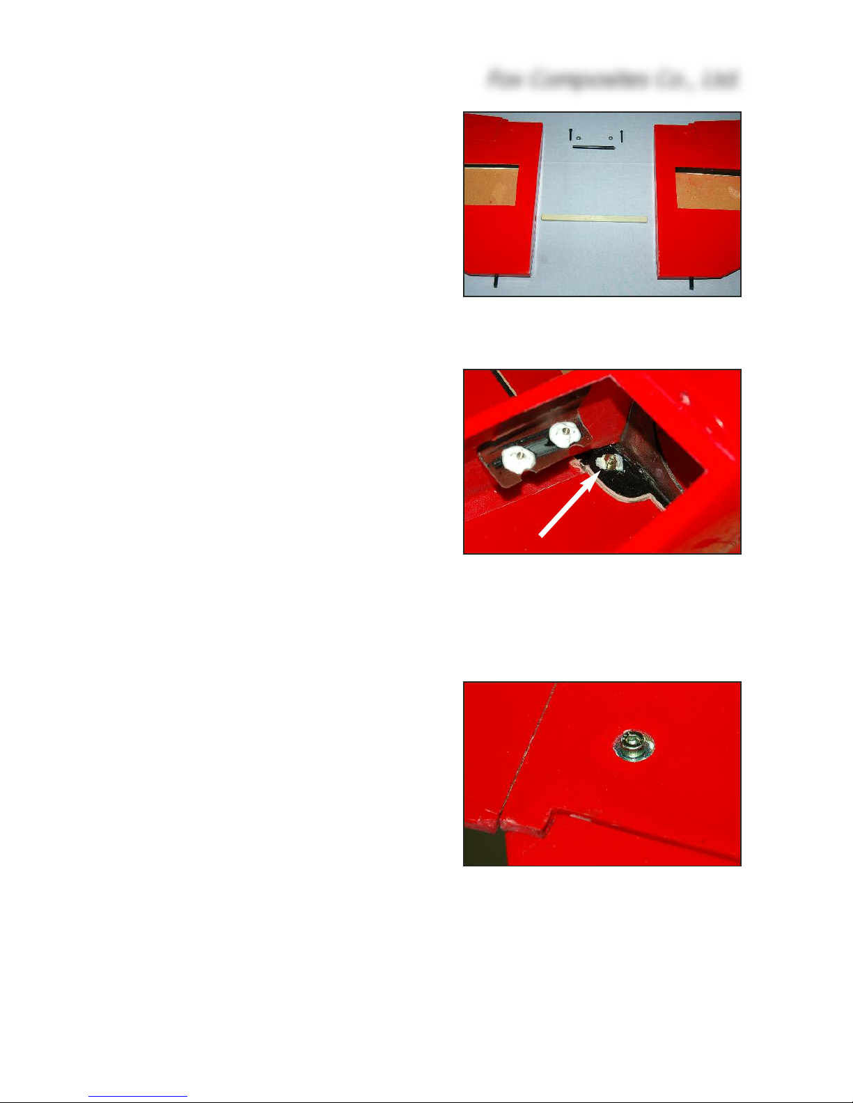
(above) T-nuts for the wing bolts are
glued onto the composite plate (arrowed). You can also see the T-nuts for
the turbine mounting here.
(below) Counterbore holes in wing underside for the M4 bolts & washers.
(above) Wing panels are joined with a
rectangular fibreglass rod and a Ø 7mm
dowel just in front of the trailing edge.
I
MPORTANT: Wait a minute
b
efore joining the wing panels
together - to make sure that the
glue does not slowly push the
joiners out of the wing they are
glued into. In this case you will
need to drill a very small (1mm)
hole through the sides of the
tubes at the outboard end (access from the landing gear bay)
to release the hydraulic pressure caused by the glue.
Now slide the wings together,
and bolt them to the fuselage,
which is supported upsidedown in a model stand, and
leave until the glue has completely cured. When the epoxy
has cured they should slide
apart easily. Remove the wax
from the exposed joiners and
wing roots with lighter-fluid. You can apply some soft pencil lead (graphite) to the exposed half of
the fibreglass wing joiner if it is a bit tight to make it slide smoothly into the other wing.
Servo Installation
Aileron servos
The ‘U-shaped’ milled lite-ply mounts for the aileron
servos are sized to suit the 30mm wide JR DS-161
or Hitech 5125 servos, but can be sanded to fit the
33mm wide JR DS-3301 or Graupner DS-3328 if
you prefer to use these - and they have slightly more
torque and larger gears. In any case we recommend
that you use aileron servos with a minimum of 4kg
torque. Fit the servos in the opposite orientation in
the 2 wings so that you can Y-lead them together,
and use a single Rx channel for operation.
Sand the upper surface of the 2 ply mounts and glue
them onto the 6mm thick balsa sheet doublers, as
shown, to position the servos closer to the lower
wing surface. Don’t forget to make a ‘left’ and a ‘right’
servo mount ! Sand the mounts and square-off the
radiused corners as necessary so that your servos
are snug fit. Centre the servos using your Transmitter, fit short servo arms at 90° to the case, set travels to 100%, and screw the servos onto the mounts.
Trial fit the mounts into the wing, and check that the
front of them fits up against the back of the wing
spar, and that the linkage will be exactly parallel to
Fox Composites Co., Ltd.
7
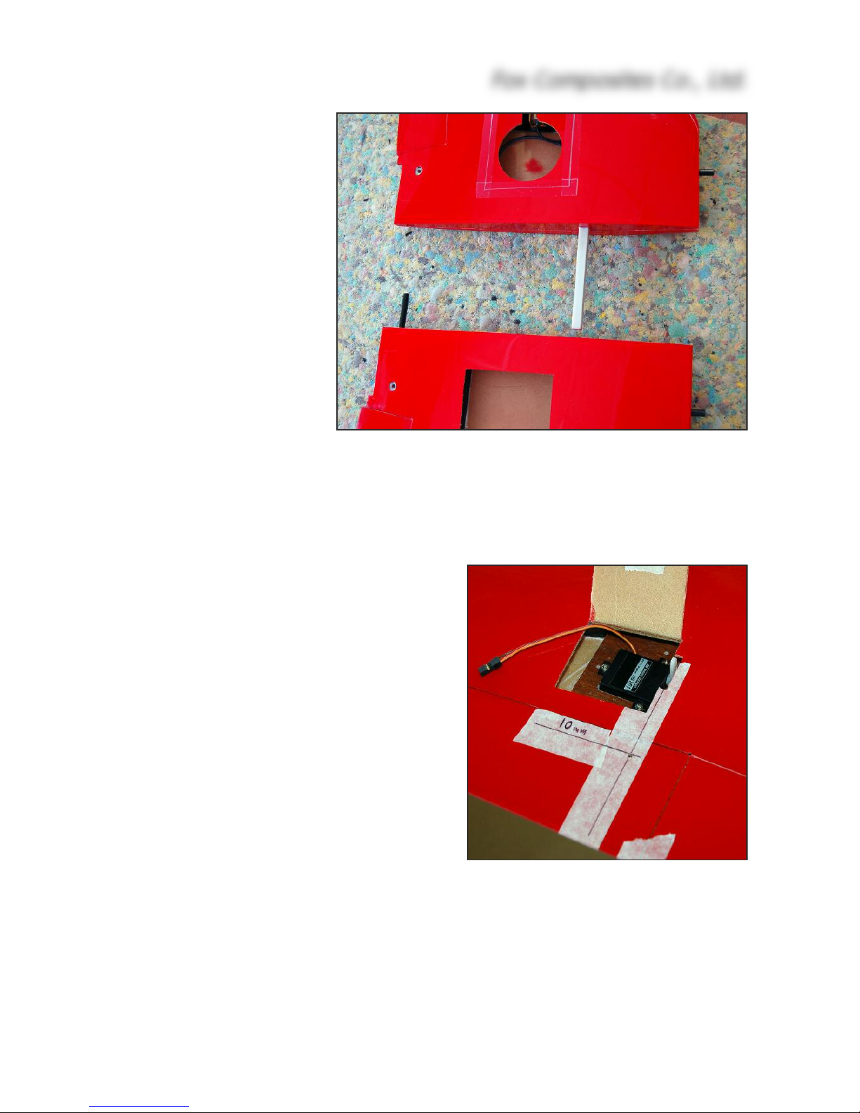
(above) Digital DS161 servo installed in
the milled ply mounts supplied in the kit.
Note the slot cut out for the servo arm,
the linkage line marked on the tape, and
the hole for the aileron horn 10mm back
from the aileron leading edge. The
aileron horn must be installed exactly in
line with the servo arm.
(above) Wing bolts & joiners completed. Note that they are
glued into opposite panels for the best fit, using slow epoxy.
t
he wing root, in line with the
a
ir-flow during flight. This only
a few degrees off the ‘ideal’ 90°
to the hinge line of the ailerons,
and is close enough that there
is no noticeable binding or lost
movement. If you want to add
‘scale’ linkage covers later you
will need the linkages at this
angle, and not at 90 degrees to
the aileron leading edge.
File or sand the 5mm x 20mm
notches on the inner edges of
the servo hatches, as shown,
for the servo arms to exit the
wing. Carefully sand the inside
surface of the wing skin and
back of the wing spar where
the mounts will be glued for a
good bond, and clean off the
dust. Glue the mounts into the
wing using a little 30 minute
epoxy and micro-balloons mixture. When cured, remove the
servos and apply a fillet of glue
all around the mounts, also
making sure that they are firmly
glued to the back of the spar.
Tape the ailerons in the neutral
position. Carefully mark the line
(on masking tape) of the linkage, exactly in line with the
servo arms and perpendicular
to the wing root. The control horns are made from the 35mm lengths of M3 threaded rod included
in the hardware. Insert the small plywood reinforcing strips (6 x 15 x 30mm) into the inboard ends
of the ailerons, in line with the linkage, and glue in place to the aileron leading edge and lower skin
with a little 30 minute epoxy and micro mixture.
Drill right thru' the aileron on the marked line, exactly 10mm behind the front edge of the aileron,
using a sharp Ø 2.2 or 2.3mm drill. Use a 90° square to keep the drill perpendicular to the bottom
surface of the elevators. The holes should be just behind, or against, the balsa elevator spars,
and must pass thru’ the ply reinforcing strips. Now thread these holes, right thru' the ailerons, using
an M3 tap. Sand both ends of the threaded rod flat, and screw on the plastic adapter provided.
Screw it into the tapped hole until the upper end is flush with the top surface of the aileron. The
M3 rod must now be secured in place, by applying glue through the open (root) end of the aileron.
Apply one drop of thick CA and, when cured, add some 30 minute epoxy and micro-balloons mixture to fill the space between the ply reinforcing strips and upper skin.
Make up the linkages between the servos and aileron horns using M2, M2.5 or 2 x 56 UNC clevises and threaded rods. The linkages will need to be approx. 55mm long, clevise pin-to-pin. Fit
Fox Composites Co., Ltd.
8
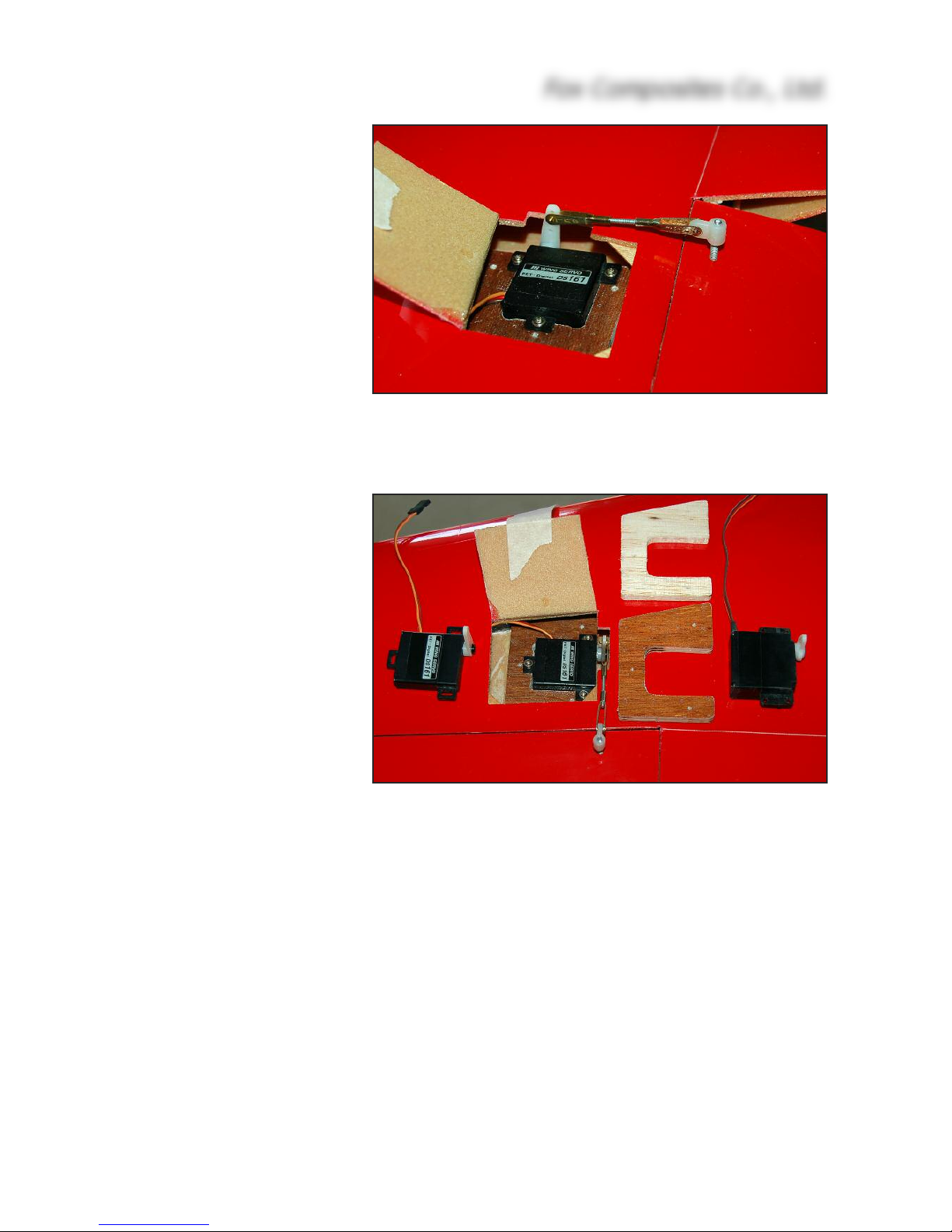
(above) Completed aileron servo, linkage and horn.
(below) We advise you to use ‘wing-mount’ servos with integral mounting tabs, like the digital JR DS-161 and DS3301/3328 servos shown here.
t
he clevise on the servo arm as close to the servo
c
entre as possible, and the clevise on the elevator
horn as far out from the elevator as possible - to
maximise the mechanical advantage, whilst still obtaining the maximum necessary aileron throws of
9mm up and down. Lengthen the servo arm exit slot
to clear the linkage on max. throws if needed.
IMPORTANT: Do NOT use ball-joints or ball-links on
the plastic horn adapters. They will cause twisting,
and almost certain flutter ! This also applies to the
rudder linkage.
When the linkages are finally adjusted the servo
hatches can be held closed with small strips of clear
tape. It is not necessary to secure them with screws.
Some small triangles of very thin ply or fibreglass
sheet glued inside the corners of the servo bays
keep the hatches flush with the wing skin.
Flap Servos
The flap servos require a little patience to install and
set up, but result in a very nice system that is completely hidden within the wing.
The servos are fitted in 6mm thick milled liteply
mounts that you glue into the wing, sized to suit
‘standard’ sized servos, and we recommend that you
use servos with not less than 6kg torque as the
Hawk flaps have quite a large surface area. We prefer to use a digital servo with at least 8kg torque, and
have installed JR 8311’s here.
If you want to use a single Rx channel and Y-lead
for operating the two flap servos, then you must fit
them both in the same orientation. In this case, then
the left flap servo will be fitted at the inboard side of
the hatch, and the right flap servo at the outboard
side of the hatch, as shown in the photos here.
Of course it is even easier to use a ‘Matchbox’ (or
equivalent) on one servo so that you can reverse it,
and adjust centres and end-points to match the other
one perfectly - and in this case you can install the
flap servos in 'mirror-image' (like the aileron servos).
As with the aileron linkages, we also prefer to make the flap linkages parallel to the wing root - although as they are fully hidden in the wing you can also choose to make them perpendicular to
the flap leading edges if you prefer. It’s your choice, and the angular difference is so small (6.5°)
that it does not affect the operation.
Carefully mark the line of both linkages on masking tape before starting. Centre both servos using
Fox Composites Co., Ltd.
9
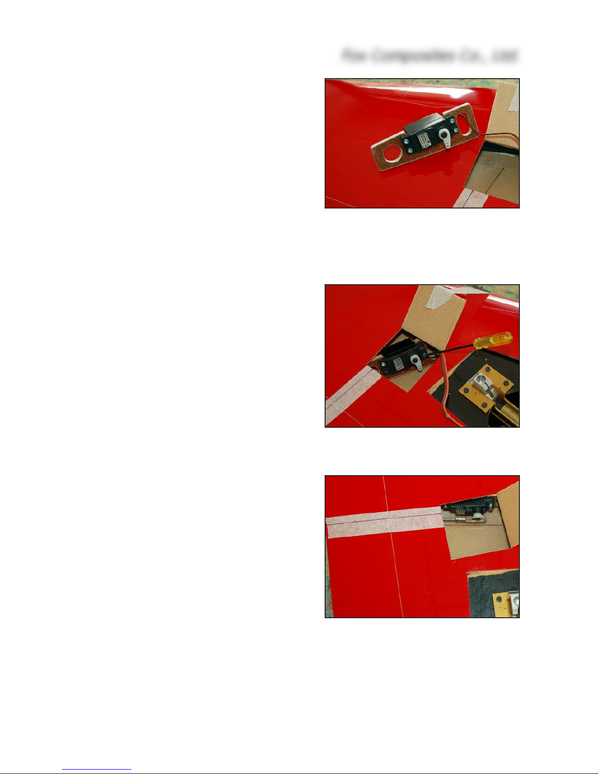
(above) Secure flap servos to mounts
with allen-head screws for easy removal.
(below) Hold plywood mount at an angle
inside the hatch to screw the servo into
place when trial fitting. Right wing shown.
(below) Notice that the servo is at a slight
angle to the hatch sides, but parallel to
the wing root. Right wing shown.
y
our transmitter and fit short servo arms now, at 90°
t
o the servo case in the neutral position. Check that
the milled mounts fit inside the wing (with the front
edge against the spar) without being too tight, sand
the U-shaped slots as necessary to fit your servos,
and drill the holes for the mounting screws. If you
use allen-head sheetmetal screws for this it is much
easier to remove the servos later using a ball-ended
allen wrench, because of the angle needed to access the screws thru’ the hatch. Cut holes as needed
for lightening and servo cable routes.
Note that the mount for the left wing is supplied
12mm longer to allow you to install them in the same
orientation, if you wish, as shown. If you use a 2
channels, a Matchbox, or one reversed servo, and
install the servos in mirror-image, then you can cut
the extra length off the front of the mount, and fit both
at the outboard side of the servo hatches.
We highly recommend that you install both mounts,
servos, linkages and horns and just tack everything
into place temporarily with very small drops of CA to
check for similar operation before gluing anything in
place permanently with epoxy and micro-balloons.
Install the flap horns before the servo mounts. They
should be close to the mid-span of the flap; we fitted
both 195mm outboard from the flap roots, so that the
servos are positioned at the edge of the servo
hatches - giving the shallowest angle for installing/removing the servo screws.
Take both the supplied fibreglass flap horns, lay them exactly on top of each other (sand
to make the shapes identical if
needed) and drill the hole
through the front for the clevise
pins, in the position shown in
the photos. Keep the hole at
least 3mm from the edge of the
horns. Scuff up both sides that
will be glued inside the flaps.
Mark the flap horn position on
the leading edge of the flaps,
and file slots 3mm wide and
12mm high against the upper
skin of the flaps.
Insert the horns, with the
curved part upwards, and push
Fox Composites Co., Ltd.
10
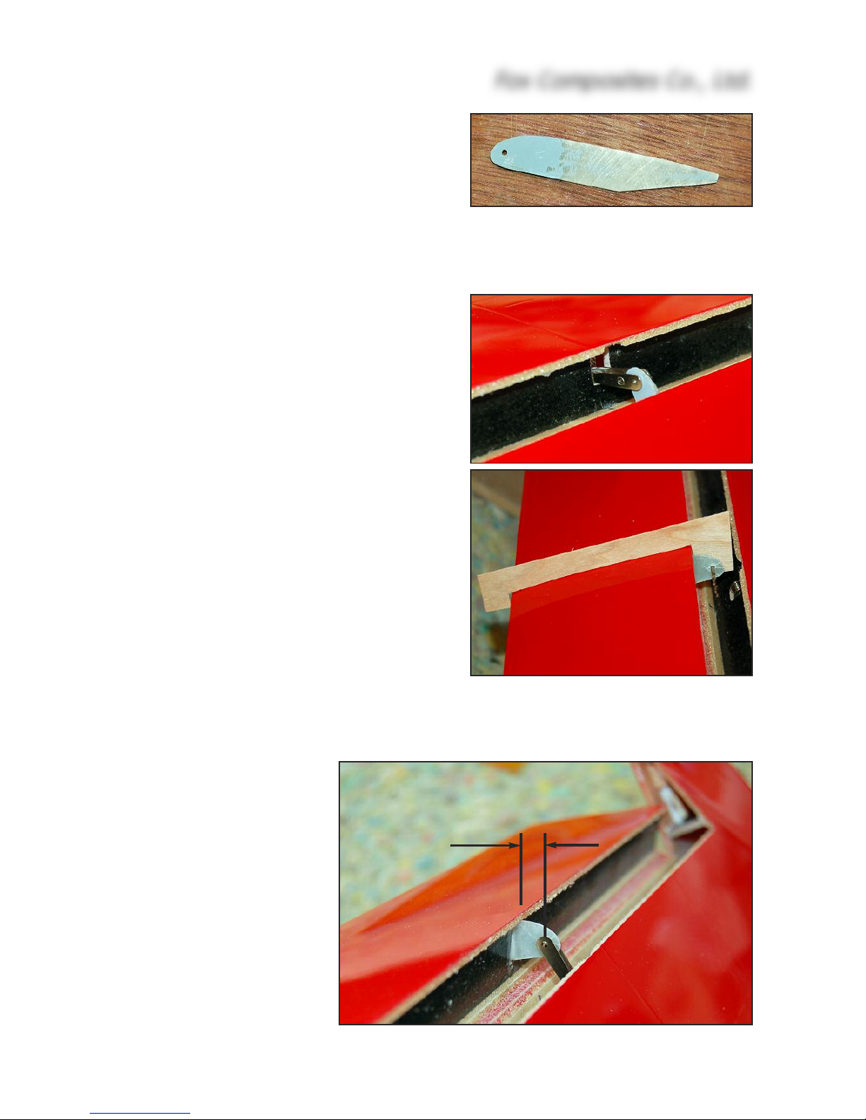
(above) Template made from scrap ply or card and a Ø
1.5mm drill sets both flap horns in identical positions.
(below) Flap horn glued in, with curved part at top, and
clevise hole 7 - 8mm in front of aileron top skin.
7 - 8mm
(above) Flap servo horn drilled for clevise pin, and prepared for installation.
(below) Sand 6 x 12mm slot in the wing
trailing edge for the flap horn & linkage.
t
hem into the flaps until the holes for the clevises are
7
- 8mm in front of the leading edge of the flap.
Especially if you want to connect the servos together
on a Y-lead and use a single channel it is important
to have the horns in identical positions on both flaps.
Make a small template from scrap plywood and an
old drill bit to copy the position of the first flap horn
to the other flap, as shown here. Tack glue both
horns in place with a small drop of thick CA. File
matching slots (approx. 6 x 12mm) in the trailing
edge of the wing for the horn & linkage to pass thru’.
Carefully prepare the inside of the wing skins where
the mounts will be glued in place. Insert the ply servo
mounts (only) into the wing, and hold them at an
angle so that you can insert the servos and screw
them into place thru’ the hatches. Just 2 servo
screws is enough for trial fitting. Twist the mounts
vertical again, push them forward to make contact
with the wing spar, and set the angle of the servo
arm parallel to the flap horns. Tack in place with a
drop of thick CA. Make up the linkages from your
preferred hardware - we used M3 threaded rod and
steel clevises, and they will need to be approx.
100mm long, clevise pin-to-pin.
NB: To obtain the best mechanical advantage (and
holding power) for the flaps you must set your servo
throws to the maximum possible and fit the clevise
into a hole on the servo arm as close as possible to
the servo centre !
Connect the linkages to the hole approx. 10mm from
the centre of the servo horn, with the servo horns
angled approx. 45° forward for
the ‘up’ flap position, and check
the flap travel by hand. You
only need 40° - 45° max. travel
for landing. When you are satisfied with both flap travels,
carefully remove the servos
and permanently glue the
mounts into place with slow or
30 min. epoxy and micro-balloons, making sure they are secured to the wing spar.
Also glue the flap horns securely to the inside surface of
the flaps, inserting the glue on
the end of a thin stick.
Fox Composites Co., Ltd.
11
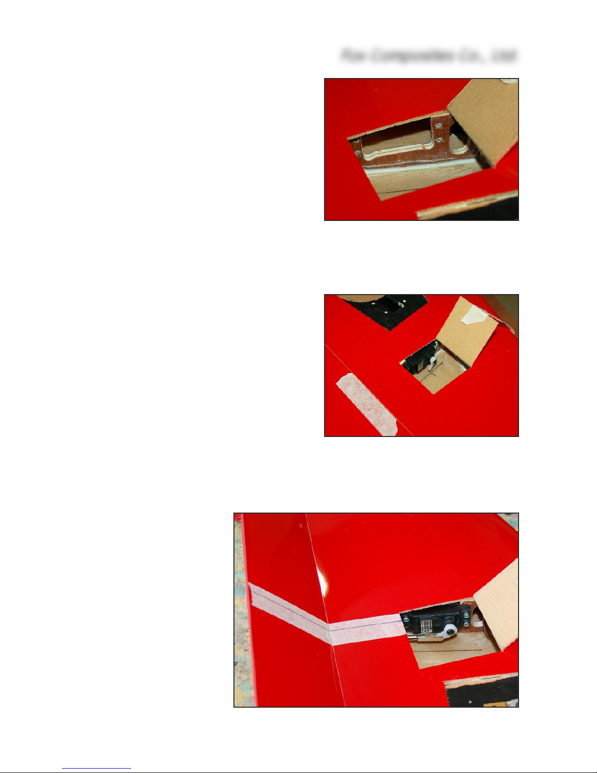
(below) Completed flap servo installation in right wing, at the outboard side
of the hatch, with flap in the fully down
(‘landing’) position, and the servo arm
angled backwards at about 45°.
(above) Ply mounts secured with a fillet
of epoxy/micro-balloons all around.
(below) Flap servo installed in left wing,
at inboard side of hatch, using the 12mm
longer plywood mount supplied.
 Loading...