

Foxcom Sat-Light 7410F, Sat-Light 7410FT, Sat-Light 7410FR Installation And User Manual

7410F Interfacility Link
Installation and User’s Guide
Copyright 2003

7410F IFL Installation and Users Guide
7410F Interfacility Link
Installation and User’s Guide
Foxcom Inc.
Princeton Forrestal Village
136 Main Street, Suite 300
Princeton NJ 08540
USA
Tel: 609-514-1800
Toll Free: 1-866-ONEPATH
Fax: 609-514-1881
Foxcom Ltd.
Beck Science Center
8 Hartom Street, Har-Hotzvim
P.O. Box 45092
Jerusalem 91450
Israel
Tel: +972-2-589-9888
Fax: +972-2-589-9898
Website: www.foxcom.com
e-mail: sales@foxcom.com
This manual contains PROPRIETARY and CONFIDENTIAL information of
Foxcom Inc. Reproduction, release to any third party, or any other unauthorized
use, of any information contained herein is expressly prohibited.
Foxcom Proprietary Information 2
Document No. 93-006-01-A

7410F IFL Installation and Users Guide
Table of Contents
1. Front Chapter................................................................................................7
1.1 Warranty and Repair Policy .................................................................... 7
1.2 Reporting Defects.................................................................................... 9
1.3 Certification............................................................................................. 9
1.4 Conventions............................................................................................. 9
1.5 Precautions ............................................................................................ 10
2. Introduction to the 7410F IFL ................................................................... 11
2.1 Options .................................................................................................. 11
2.2 Product Drawings .................................................................................. 13
2.3 Panel Descriptions................................................................................. 14
2.4 Block Diagrams..................................................................................... 15
3. Installation ................................................................................................... 16
3.1 Setting Up the Transmitter .................................................................... 17
3.2 Connecting the Fiberoptic Cable........................................................... 18
3.3 Setting Up the Receiver......................................................................... 19
3.4 Powering the IFL................................................................................... 20
3.5 Connecting the Back Panel Jumpers ..................................................... 21
3.6 Monitoring the Input/Output Signal...................................................... 24
3.7 Aligning the Fiberoptic Link................................................................. 24
4. Product Technical Description...................................................................25
4.1 7410F IFL Specifications ...................................................................... 25
4.2 Model Dimensions ................................................................................ 27
4.3 7410F IFL Pinouts................................................................................. 28
4.4 7180M Chassis Pinouts ......................................................................... 32
5. Troubleshooting...........................................................................................36
6. Appendix I Cleaning Fiberoptic Connections........................................... 38
6.1 Cleaning Procedures for FC/APC Connectors ...................................... 39
6.2 Cleaning Procedure for FC/APC Bulkhead Ports ................................. 40
7. Appendix II Installing a Standalone Unit .................................................41
8. Appendix III The 2380 Relay Adaptor...................................................... 42
8.1 Installing the 2380 - Parts Needed ........................................................ 42
8.2 Installing the 2380 - Procedure ............................................................. 42
8.3 2380 Dimensions and Front Panel Label .............................................. 44
Foxcom Proprietary Information 3
Document No. 93-006-01-A

7410F IFL Installation and Users Guide
8.4 2380 Pinouts .......................................................................................... 45
9. Appendix IV 7100M Chassis...................................................................... 47
9.1 Equipment Safety .................................................................................. 47
9.2 Installation ............................................................................................. 48
9.3 Model Dimensions ................................................................................ 54
9.4 7410F IFL Pinouts (7100M Chassis) .................................................... 55
9.5 7100M Pinouts ...................................................................................... 59
9.6 The 2300 Relay Adaptor ....................................................................... 63
9.7 Changing the Primary Power Setting .................................................... 69
10. Appendix V Pinouts, Detailed Information .......................................... 71
List of Figures
Figure 1 - Option Label ......................................................................................... 12
Figure 2 - 7410FT Transmitter Panels .................................................................. 13
Figure 3 - 7410FR Receiver Panels....................................................................... 13
Figure 4 - 7410FT Transmitter Block Diagram .................................................... 15
Figure 5 - 7410FR Receiver Block Diagram......................................................... 15
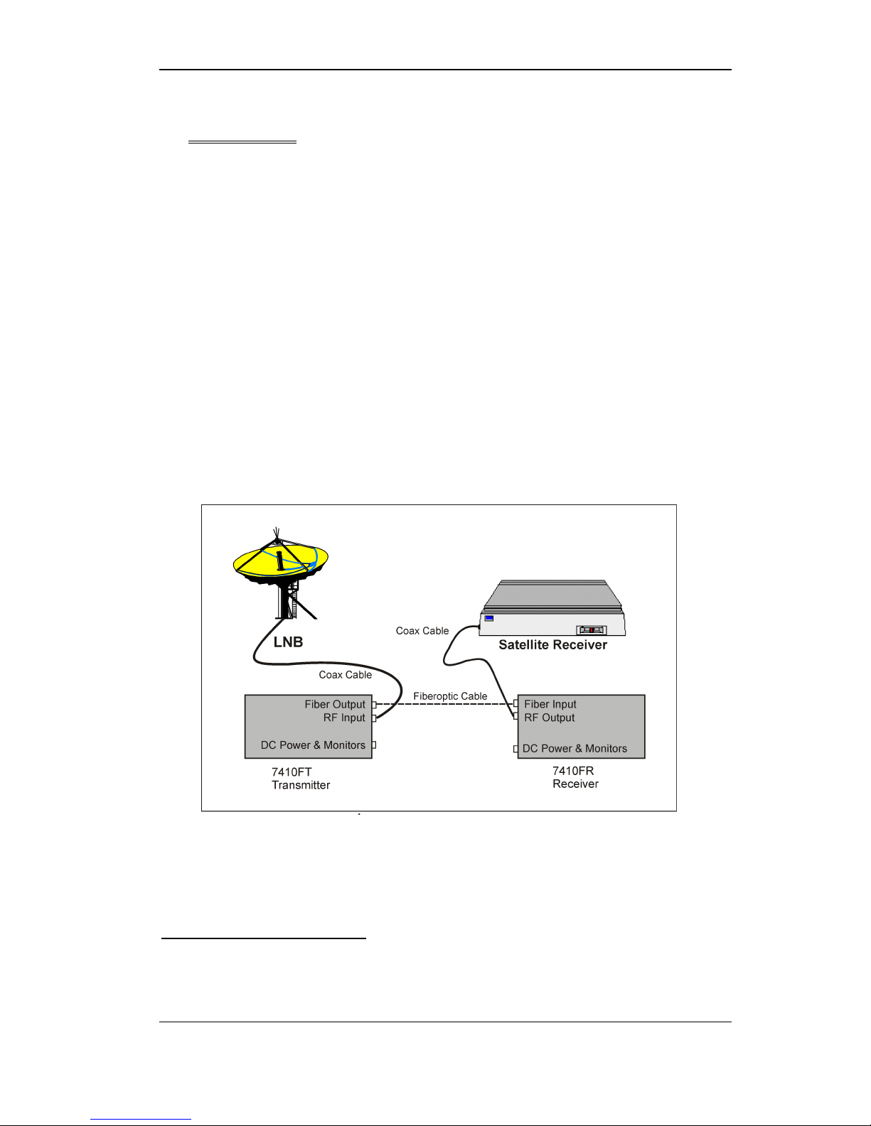
Figure 6 - Typical Application of a 7410F Link ................................................... 16
Figure 7 - 7180M Chassis Rear View ................................................................... 21
Figure 8 - Jumper Installation: Tx and Rx Only ................................................... 22
Figure 9 - Jumper Installation: 2000 Switch in Slot 2........................................... 22
Figure 10 - Jumper Installation: 2000 Switch in Slot 5......................................... 23
Figure 11 - Jumper Installation: 2000 Switch in Slots 2 and 5 ............................. 23
Figure 12 - Fiberoptic Alignment Setup................................................................ 24
Figure 13 - Unit Dimensions ................................................................................. 27
Figure 14 - 7180M Chassis Dimensions ............................................................... 27
Figure 15 - 7410FT Transmitter Pinout ................................................................ 29
Figure 16 - 7410FR Receiver Pinout..................................................................... 31
Figure 17 - 7180M Chassis Rear View ................................................................. 32
Figure 18 - 7180M Pin Numbers........................................................................... 35
Figure 19 - Wiping the Connector with a Kim Wipe ............................................ 39
Figure 20 - Wiping the Connector with a Kim Wipe (2) ...................................... 39
Figure 21 - Cleaning the Optical Port ................................................................... 40
Foxcom Proprietary Information 4
Document No. 93-006-01-A

7410F IFL Installation and Users Guide
Figure 22 - Cleaning the Optical Port (2).............................................................. 40
Figure 23 - Mounting the Chassis and Adaptor - Detail ....................................... 42
Figure 24 - Mounting the Pins and Adaptor.......................................................... 43
Figure 25 - Mounting the Screws (1) .................................................................... 43
Figure 26 - Mounting the Screws (2) .................................................................... 44
Figure 27 - Mounted 2380..................................................................................... 44
Figure 28 - 2380 Dimensions ................................................................................ 44
Figure 29 - 2380 Front Label ................................................................................ 44
Figure 30 - 2380 Pin Numbers .............................................................................. 46
Figure 31 - 7100M Chassis Rear View ................................................................. 51
Figure 32 - Jumper Installation: Tx and Rx Only ................................................. 52
Figure 33 - Jumper Installation: 2000 Switch in Slot 2......................................... 52
Figure 34 - Jumper Installation: 2000 Switch in Slot 5......................................... 53
Figure 35 - Jumper Installation: 2000 Switch in Slots 2 and 5 ............................. 53
Figure 36 - Unit Dimensions ................................................................................. 54
Figure 37 - 7100M Chassis Dimensions ............................................................... 54
Figure 38 - 7410FT Transmitter Pinout ................................................................ 56
Figure 39 - 7410FR Receiver Pinout..................................................................... 58
Figure 40 - 7100M Chassis ................................................................................... 59
Figure 41 - 7100M Pin Numbers........................................................................... 62
Figure 42 - Mounting the Chassis and Adaptor - Detail ....................................... 63
Figure 43 - Mounting the Pins and Adaptor.......................................................... 64
Figure 44 - Mounting the Screws (1) .................................................................... 64
Figure 45 - Mounting the Screws (2) .................................................................... 65
Figure 46 - Mounted 2300..................................................................................... 65
Figure 47 - 2300 Dimensions ................................................................................ 66
Figure 48 - 2300 Front Label ................................................................................ 66
Figure 49 - 2300 Pin Numbers .............................................................................. 68
Figure 50 - Fuse Drawer........................................................................................ 69
Figure 51 - Voltage Selector (230 Side)................................................................ 69
Figure 52 - Voltage Selector (115 Side)................................................................ 70
Foxcom Proprietary Information 5
Document No. 93-006-01-A

7410F IFL Installation and Users Guide
Figure 53 - Standard 7180M and 7180M with 2380 Relay Adaptor Pinout ......... 71
Figure 54 - 7180M with 2000 Switch Pinout ........................................................ 71
Figure 55 - Pinout of 7180M Jumper with 2000 Switch in Slot 2 and 5............... 71
Figure 56 - Pinout of 7180M Jumper with 2000 Switch in Slot 2 ........................ 71
Figure 57 - Pinout of 7180M Jumper with 2000 Switch in Slot 5 ........................ 71
Figure 58 - Pinout of 7180M Jumper with Tx or Rx only .................................... 71
List of Tables
Table 1 - 7410FT Transmitter LEDs..................................................................... 14
Table 2 - 7410FT Receiver LEDs ......................................................................... 14
Table 3 - 7410FT Transmitter Pinout.................................................................... 28
Table 4 - 7410FR Receiver Pinout ........................................................................ 30
Table 5 - 7180M Alarm Connector (J12) Pinout .................................................. 33
Table 6 - 7180M Monitor Connector (J13) Pinout................................................ 34
Table 7 - 7180M LNB Connector (J11) Pinout..................................................... 35
Table 8 - Troubleshooting ..................................................................................... 36
Table 9 - 2380 Alarms Pinout (J2) ........................................................................ 45
Table 10 - 2380 Monitor Connector Pinout (J4) ................................................... 46
Table 11 - 7410FT Transmitter Pinout.................................................................. 55
Table 12 - 7410FR Receiver Pinout ...................................................................... 57
Table 13 - 7100M Alarm Connector (J9) Pinout .................................................. 60
Table 14 - 7100M Monitor Connector (J10) Pinout.............................................. 61
Table 15 - 7100M LNB Connector (J11) Pinout................................................... 62
Table 16 - 2300 Alarms Pinout (J2) ...................................................................... 67
Table 17 - 2300 Monitor Connector Pinout (J4) ................................................... 68
Table 18 - AC Voltage Fuse Part Numbers........................................................... 70
Table 19 - DC Voltage Fuse Part Number ............................................................ 70
Foxcom Proprietary Information 6
Document No. 93-006-01-A

7410F IFL Installation and Users Guide
1. Front Chapter
Front Chapter
1.1 Warranty and Repair Policy
Foxcom performs testing and inspection to verify the quality and reliability
of our products. Foxcom uses every reasonable precaution to ensure that
each unit meets specifications before shipment. Customers are asked to
advise their incoming inspection, assembly, and test personnel as to the
precautions required in handling and testing our products. Many of these
precautions are to be found in this manual.
Nullification of Warranty
The Warranty is null and void if the product casing is opened.
The products are covered by the following warranties:
A) General Warranty
Foxcom warrants to the original purchaser all standard products sold
by Foxcom to be free of defects in material and workmanship for one
(1) year from date of shipment from Foxcom. During the warranty
period, Foxcom will repair or replace any product that Foxcom proves
to be defective. This warranty does not apply to any product which
has been subject to alteration, abuse, improper installation or
application, accident, electrical or environmental over-stress,
negligence in use, storage, transportation or handling.
B) Specific Product Warranty Instructions
All Foxcom products are warranted against defects in workmanship,
materials and construction, and to no further extent. Any claim for
repair or replacement of units found to be defective on incoming
inspection by a customer must be made within 30 days of receipt of
shipment, or within 30 days of discovery of a defect within the
warranty period.
This warranty is the only warranty made by Foxcom and is in lieu of
all other warranties, expressed or implied. Foxcom sales agents or
representatives are not authorized to make commitments on warranty
returns.
C) Returns
In the event that it is necessary to return any product against above
warranty, the following procedure shall be followed:
1. Return authorization is to be received from Foxcom prior to
returning any unit. Advise Foxcom of the model, serial
Foxcom Proprietary Information 7
Document No. 93-006-01-A

7410F IFL Installation and Users Guide
number, and discrepancy. The unit may then be forwarded to
Foxcom, transportation prepaid. Devices returned collect or
without authorization may not be accepted.
2. Prior to repair, Foxcom will advise the customer of our test
results and any charges for repairing customer-caused
problems or out-of-warranty conditions etc.
3. Repaired products are warranted for the balance of the original
warranty period, or at least 90 days from date of shipment.
D) Limitations of Liabilities
Foxcom's liability on any claim, of any kind, including negligence for
any loss or damage arising from, connected with, or resulting from the
purchase order, contract, quotation, or from the performance or breach
thereof, or from the design, manufacture, sale, delivery, installation,
inspection, operation or use of any equipment covered by or furnished
under this contact, shall in no case exceed the purchase price of the
device which gives rise to the claim.
Front Chapter
EXCEPT AS EXPRESSLY PROVIDED HEREIN, FOXCOM
MAKES NO WARRANTY, EXPRESSED OR IMPLIED, WITH
RESPECT TO ANY GOODS, PARTS AND SERVICES
PROVIDED IN CONNECTION WITH THIS AGREEMENT
INCLUDING, BUT NOT LIMITED TO, THE IMPLIED
WARRANTIES OF MERCHANTABILITY AND FITNESS FOR
A PARTICULAR PURPOSE. FOXCOM SHALL NOT BE
LIABLE FOR ANY OTHER DAMAGE INCLUDING, BUT NOT
LIMITED TO, INDIRECT, SPECIAL OR CONSEQUENTIAL
DAMAGES ARISING OUT OF OR IN CONNECTION WITH
FURNISHING OF GOODS, PARTS AND SERVICE
HEREUNDER, OR THE PERFORMANCE, USE OF, OR
INABILITY TO USE THE GOODS, PARTS AND SERVICE.
The Company's exclusive warranty and the remedy provided for
breach thereof shall not apply to (a) any Product used or operated other
than pursuant to the Company's written instructions, (b) damage or
deficiencies resulting from accident, alteration, modification, misuse,
tampering, negligence, improper maintenance, installation or abuse, (c)
use of any Product other than at the Installation Site, (d) use of any
Product that is defective or damaged due to misuse, accident, or
neglect, or due to external electrical stress, lightning or other acts of
nature, (e) use of any Product by a person who is not any authorized
employee of the Customer, or (f) used other than as explicitly
authorized in writing by the Company.
Foxcom Proprietary Information 8
Document No. 93-006-01-A

7410F IFL Installation and Users Guide
1.2 Reporting Defects
The units were inspected before shipment and found to be free of mechanical
and electrical defects. Examine the units for any damage which may have
been caused in transit. If damage is discovered, file a claim with the freight
carrier immediately. Notify Foxcom as soon as possible.
Note
Keep all packing material until you have completed the inspection.
1.3 Certification
The 7410F IFL has CE, FCC, FDA, and UL certification.
1.4 Conventions
In this manual the following special formats are used:
Note
Front Chapter
Notes contain information detailing the current topic.
CAUTION
Cautions contain information regarding situations or materials which
could damage your product.
WARNING
WARNINGS CONTAIN INFORMATION REGARDING DANGEROUS
FUNCTIONS.
Foxcom Proprietary Information 9
Document No. 93-006-01-A

7410F IFL Installation and Users Guide
1.5 Precautions
1.5.1. Personal Safety
WARNING
OPTICAL RADIATION
APPLYING POWER TO THE TRANSMITTER UNIT WILL
CREATE A LASER ENERGY SOURCE OPERATING IN CLASS I
AS DEFINED BY IEC 825-1. USE EITHER AN INFRARED
VIEWER, OPTICAL POWER METER OR FLUORESCENT
SCREEN FOR OPTICAL OUTPUT VERIFICATION.
AC POWER HAZARD
THE RACKMOUNT POWER SUPPLY LINE IS EMI FILTERED.
THE CHASSIS IS CONNECTED TO EARTH GROUND IN
COMPLIANCE WITH SAFETY REQUIREMENTS. ALWAYS USE
THE 3 PRONG AC PLUG WITH EARTH GROUND TO AVOID
POSSIBILITY OF ELECTRICAL SHOCK HAZARD TO
PERSONNEL.
Front Chapter
1.5.2. Equipment Safety
1. Fuses: The 7180M does not have fuses. If the unit fails, pull the
power supply out from the chassis and then push it back in.
2. The input of the transmitter has an optional built-in bias for
inserting DC power up the coax to the LNB. Make certain any
equipment or test equipment connected to the transmitter input can
withstand this bias.
3. The output of the receiver is AC coupled and can withstand the bias
from a satellite receiver. Do not exceed 25V DC bias.
4. Do not allow any dirt or foreign material to get into the optical
connector bulkheads. This may cause damage to the polished optical
connector end faces.
5. The optical fiber jumper cable bend radius is 3 cm. Smaller radii
can cause excessive optical loss and/or fiber breakage.
6. If multiple transmitters are installed in the chassis allow sufficient
room for adequate ventilation; otherwise the units may overheat
causing possible safety hazard or equipment damage.
7. When several units are installed on one 7180M chassis, ensure that
the total current consumption (including any LNB bias) does not
exceed 6A per chassis.
Foxcom Proprietary Information 10
Document No. 93-006-01-A

7410F IFL Installation and Users Guide
Introduction to the 7410F IFL
2. Introduction to the 7410F IFL
The Sat-Light 7410F IFL transmits an L-Band RF signal over singlemode fiber
from a satellite antenna LNB to control room equipment up to two kilometers
away. The 7410F IFL consists of an optical transmitter (7410FT) which receives
the L-Band signal from the LNB and an optical receiver (7410FR) which connects
to a satellite receiver.
The 7410FT and 7410FR modules plug into the 7180M1, a 3U chassis/power
supply, which enables expansion of the system to accommodate any 8 Sat-Light
modules. Accessories include the Model 7001P Power Supply, the Model 2000
1:1 Redundant Switch, the Model 2100 Amplifier, the 2300 Relay Adaptor, and
the Model 7050 Serial Data Multiplexer, an asynchronous data link.
The 7410F IFL is a broadband transmission link; all standard satellite modulation
formulas can be transmitted (i.e. QPSK, FM, etc.). The RF signal is directly
modulated and adds virtually no phase noise to the original signal. The direct
modulation, coupled with the 7410F Links RF circuitry, guarantees superior signal
quality. The 7410F gives more than 30 dB carrier to noise performance in a full
multichannel environment.
Automatic Gain Control (AGC) at the transmit site provides for optimized signal
levels over various input power levels. Manual Gain Control (MGC) at the
receive site provides compensation of any signal loss caused by the link. LEDs,
and back panel monitors and alarms allow for complete system status monitoring
and for interfacing with monitor and control (M&C) systems.
2.1 Options
The 7410F IFL comes with a variety of options:
1. LNB powering; the transmitter unit can provide 14 VDC for optional
LNB powering.
2. 50 Ω Input/Output Impedance/BNC or SMA RF connector; standard
impedance is 75 Ω/F type, female connectors.
3. Standalone unit; the 7410F IFL can be installed as a standalone unit. If
the 7410F is used as a standalone, a separate power supply must be
used.
1
7100M in older models; refer to Appendix IV 7100M Chassis.
Foxcom Proprietary Information 11
Document No. 93-006-01-A
7410F IFL Installation and Users Guide
Introduction to the 7410F IFL
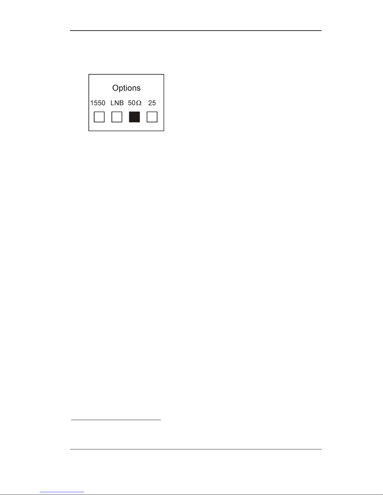
On the side of the 7410FT and the 7410FR units is a label which lists
options2. Under each option is a square. If the unit includes a particular
option the square under the option should be marked.
Figure 1 - Option Label
2
The label includes some options which are not relevant to the 7410F IFL.
Foxcom Proprietary Information 12
Document No. 93-006-01-A
7410F IFL Installation and Users Guide
Introduction to the 7410F IFL
2.2 Product Drawings
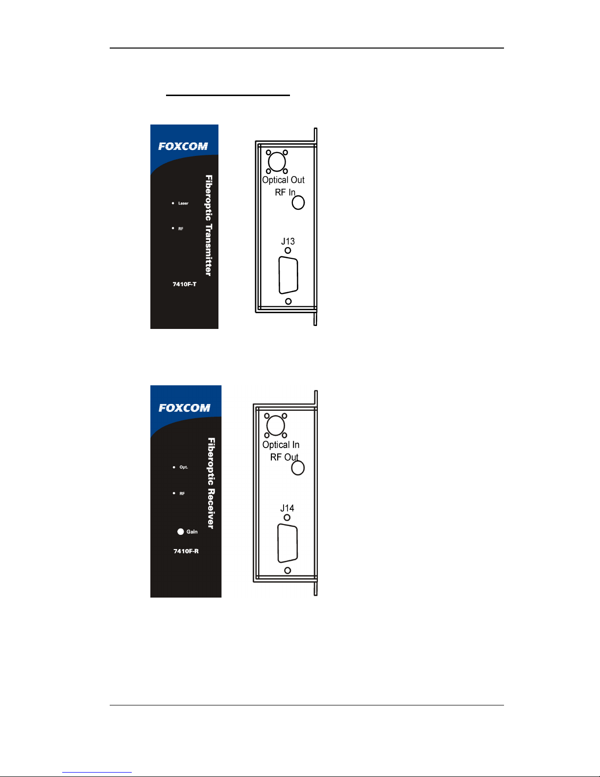
Figure 2 shows the front and rear panels of the 7410FT Transmitter units.
Figure 2 - 7410FT Transmitter Panels
Figure 3 shows the front and rear panels of the 7410FR Receiver units.
Figure 3 - 7410FR Receiver Panels
Foxcom Proprietary Information 13
Document No. 93-006-01-A
7410F IFL Installation and Users Guide
Introduction to the 7410F IFL
2.3 Panel Descriptions
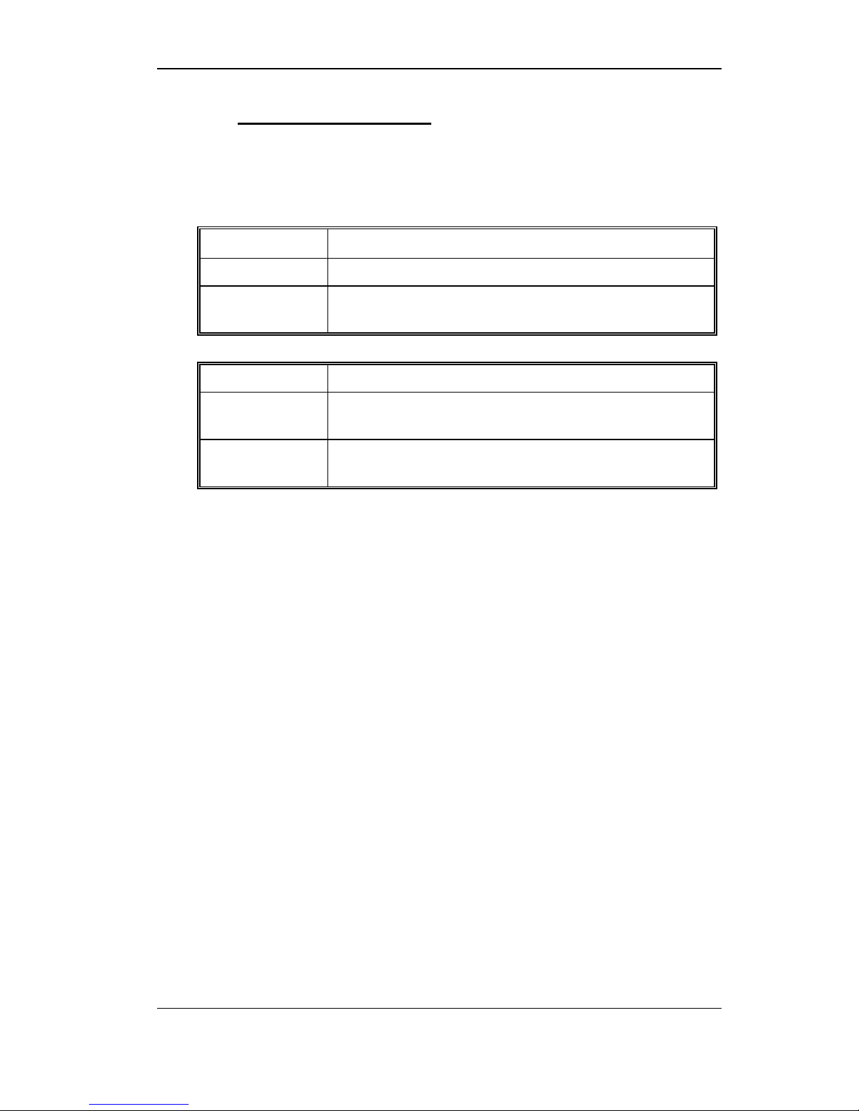
On the Front Panel of the 7410F Transmitter and Receiver unit are two
LEDs. The following tables describe the LEDs.
Table 1 - 7410FT Transmitter LEDs
LED Name LED Function
Laser
RF
Indicates that the laser is functioning
Indicates if the Automatic Gain Control is within
operating limits (-40 to -20 dBm)
Table 2 - 7410FT Receiver LEDs
LED Name LED Function
Opt.
Indicates if the optical input power is above the
minimal level (≥-7 dBm)
RF
Indicates if the RF signal is above the minimal level
(≥-40 dBm)
Foxcom Proprietary Information 14
Document No. 93-006-01-A
7410F IFL Installation and Users Guide
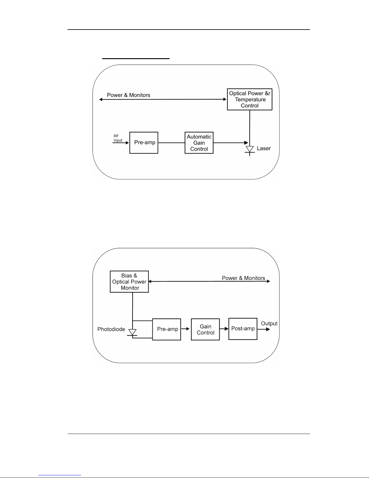
2.4 Block Diagrams
Figure 4 - 7410FT Transmitter Block Diagram
Introduction to the 7410F IFL
The 7410FT Transmitter accepts RF input signal levels ranging from
-40 to -20 dBm total power (i.e. at 10 channel loading this is equivalent to
-50 to -30 dBm per channel). The unit amplifies the signal, and feeds it to a
laser diode which linearly converts the broadband RF signal to light
intensity.
Figure 5 - 7410FR Receiver Block Diagram
The 7410FR Receiver receives the optical intensity signal, and linearly
converts the signal back to RF. The Receiver then amplifies and reproduces
the L-Band RF signal.
Foxcom Proprietary Information 15
Document No. 93-006-01-A
7410F IFL Installation and Users Guide
Installation
3. Installation
The following section details how to setup the 7410F IFL units3.
Setting up the 7410F IFL Transmitters and Receivers consists of the following
steps:
1. Setting up the transmitter
2. Connecting the fiberoptic cable
3. Setting up the receiver
4. Powering the IFL
5. Connecting the back panel jumpers
6. Monitoring the input/output signal
7. Aligning the fiberoptic link
Observe all warnings and cautions mentioned at the beginning of this manual
(page 10). If after set-up you experience problems, refer to Troubleshooting on
page 36.
Figure 6 - Typical Application of a 7410F Link
3
This section gives instructions on installing the transmitter and receiver in a chassis rackmount.
For instructions on installing standalone units refer to Appendix II Installing a Standalone Unit.
Foxcom Proprietary Information 16
Document No. 93-006-01-A

7410F IFL Installation and Users Guide
3.1 Setting Up the Transmitter
1. Place the 7410FT Transmitter in the 7180M Chassis. The operating base
plate temperature must be between -10° C to 55° C.
2. Apply AC power to the chassis. The Laser LED should be lit.
3. Using an optical power meter, measure the optical power. Insert the
meter’s cable into the Transmitter’s optical connector. Power levels should
be between 0.3 – 0.6 mW (-2 to -4 dBm).
Alternatively, use a DVM to measure the voltage at:
• pins J13-P17 through J13-P24 for the slot being measured (Refer to
Table 6 page 34 for details regarding J13 pinouts) (7180M
Rackmount)
• at pin #6 of the 9 pin connector (standalone)
The signal level should be -4.8 to -4.2 VDC.
4. On the rear panel, connect the coax cable to the RF Input Connector. The
RF LED should be lit.
Installation
5. On the rear panel, connect the fiberoptic cable to the Optical Connector.
6. The 7410FT Transmitter has AGC; no further adjustment is needed.
Note
If either LED is not lit, refer to Troubleshooting on page 36.
CAUTION
When monitoring the voltage outputs use a high resistance DVM only.
Foxcom Proprietary Information 17
Document No. 93-006-01-A
7410F IFL Installation and Users Guide
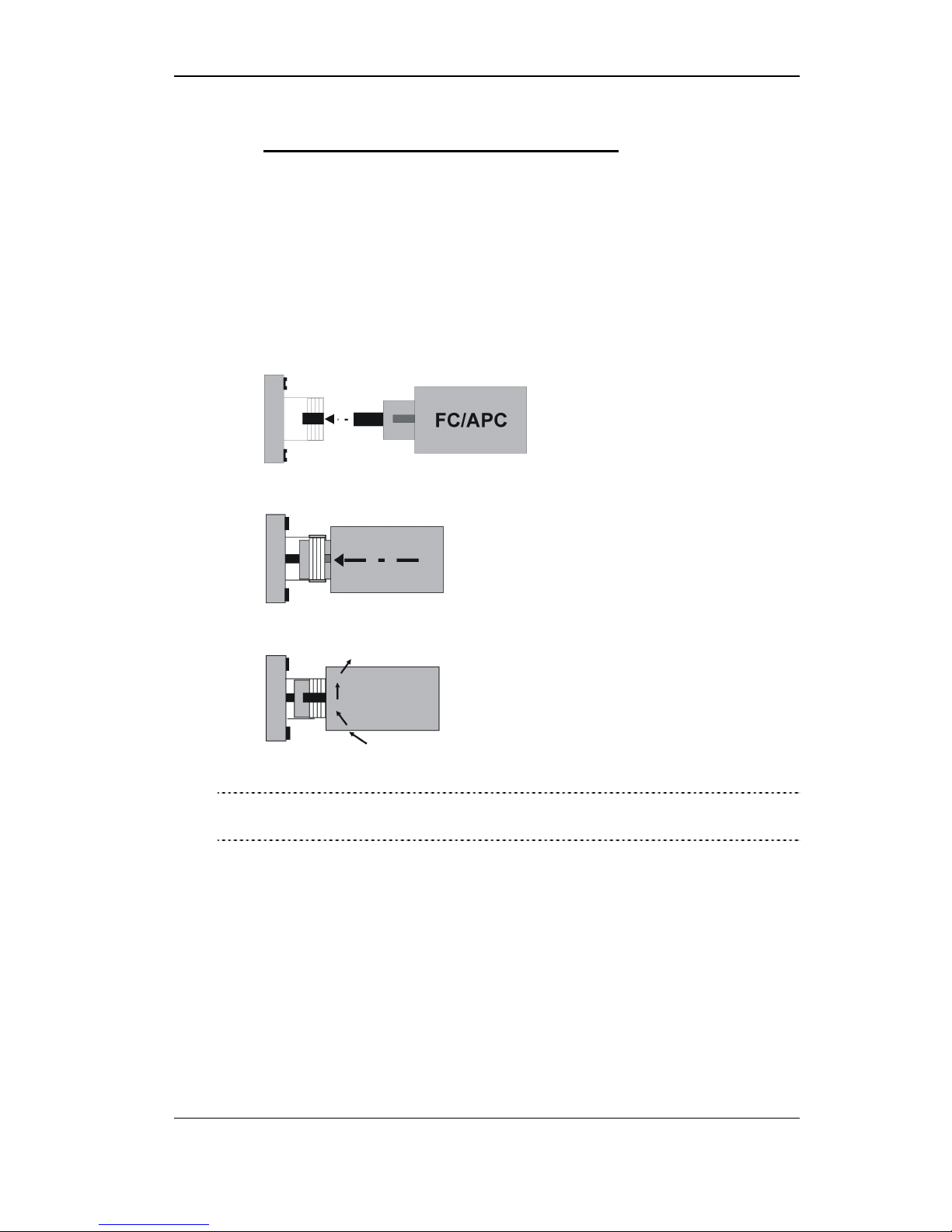
3.2 Connecting the Fiberoptic Cable
Before connecting the cable:
1. The fiberoptic cable must be either fusion spliced or connected via
FC/APC connectors.
2. Wipe the connector with a lint-free cotton cloth.
3. Note the polarity key of the optical connector before inserting.
To connect the cable:
1. Line Up the Polarity Key.
2. Insert the connector.
Installation
3. Tighten the connector.
CAUTION
Do not apply any glue, silicon adhesive, or any other material to the
fiberoptic connector!
Foxcom Proprietary Information 18
Document No. 93-006-01-A

7410F IFL Installation and Users Guide
3.3 Setting Up the Receiver
1. Place the 7410FR Receiver in the 7180M Chassis, unless a 2000 RF
Switch is installed (refer to Figure 7, page 21). The operating base plate
temperature must be between -10° C to 55° C.
Note
If a 2000 RF Switch(s) is being installed, then slots 2 and/or 5 of the 7180M
are reserved for the switch(es).
2. Apply AC power to the chassis. The Power Supply’s LED should be lit.
3. Using an optical power meter, measure the optical power coming to the
Receiver from the fiberoptic cable. The power levels of the Receiver should
be the power level measured at the Transmitter minus the fiber loss
Alternatively, use a DVM to measure the voltage at:
• pins J13-P9 through J13-P16 for the slot being measured (Refer to
Table 6 page 34 for details regarding J13 pinouts) (7180M
Rackmount). The voltage level should be 1V for each 1 mW measured
at the Receiver input.
Installation
4
.
• at pin #5 of the 9 pin connector (standalone)
4. On the rear panel connect the fiberoptic cable to the Optical Connector.
The Opt. and RF LEDs should be lit.
5. On the rear panel, connect the coax cable to the RF Output Connector.
6. Adjust the Gain Control Potentiometer to give the desired output power.
Using a small screw driver, turn the potentiometer (located on the front
panel) to increase or decrease the gain.
Note
If either LED is not lit, refer to Troubleshooting on page 36.
Note
The potentiometer is 10 turns potentiometer.
• To increase the gain, turn the potentiometer clockwise.
• To decrease the gain, turn the potentiometer counterclockwise.
For more information refer to Aligning the Fiberoptic Link on page 24.
4
Fiber loss is defined as:
(0.4 dB/km x length (km) of the fiberoptic cable) + (0.5 dB x number of connectors).
For example if a link was 10 kilometers long and had two connectors the loss would be:
(0.4 dB/km x 10 km) + (0.5 dB x 2) = 5.0 dB.
Foxcom Proprietary Information 19
Document No. 93-006-01-A

7410F IFL Installation and Users Guide
3.4 Powering the IFL
• Transmitter power requirement: +15VDC @ 300 mA
• Receiver power requirement: +15VDC @ 250 mA
• The Standalone Transmitter/Receiver can be powered by a
Foxcom-supplied external DC power supply.
• The Rackmount Transmitters/Receivers are plugged into the 7100M
rackmount chassis. The chassis can accept and power up to six units.
Note
At temperatures below 10° C, the Transmitter’s internal heater will require
an additional 100 mA. The Transmitter’s total power requirement will then
be 400 mA.
CAUTION
Ensure that there is a good airflow around the chassis rackmount.
There should be the space of a rackmount between chassis.
Installation
3.4.1. 7180M Chassis
The 7180M Chassis provides power to the plug in units. The power
supply is a switching type. Each plug-in regulates its own voltage.
The power supply provides:
• 14 VDC stable
• AC input; 100 - 240 VAC
• Units can be plugged in “hot standby”
Foxcom Proprietary Information 20
Document No. 93-006-01-A
7410F IFL Installation and Users Guide
Installation
Foxcom Proprietary Information 21
Document No. 93-006-01-A
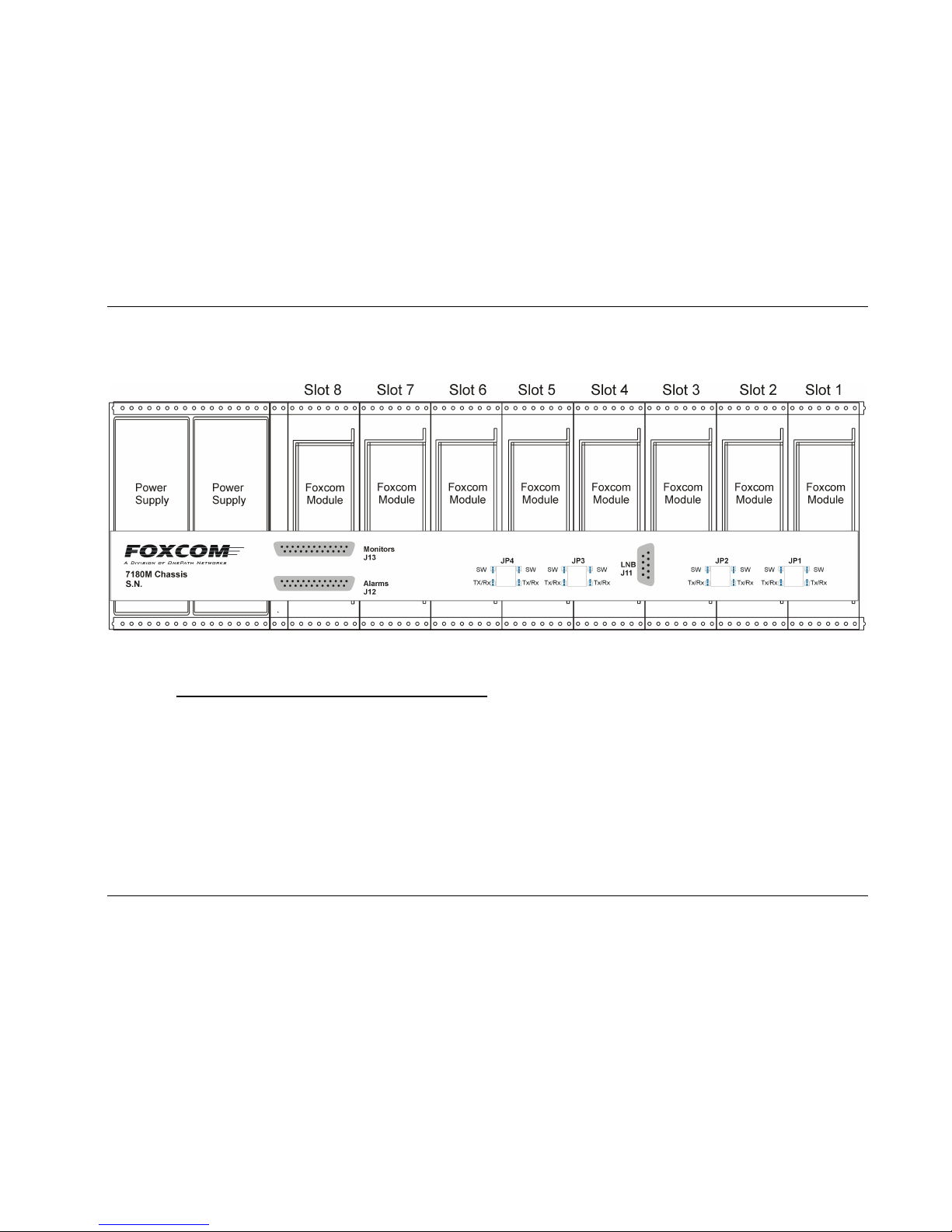
Figure 7 - 7180M Chassis Rear View
3.5 Connecting the Back Panel Jumpers
On the rear panel of the 7180M Back Panel are product selectors (JP1 to JP4). The 3 pin selectors (male) are the connecting
point between the slots and the back panel. One pin is for the transmitter/receiver (Tx/Rx), one is for the optional 2000 1:1
Redundant Switch, and one is for the 7180M. A 2 pin jumper (female) is placed on the relevant pins to complete the
connection between the 7180M and the units. For example, if a 2000 Switch is being used, the jumper is placed on the
Switch-7180M pins.
To connect the jumpers:
1. Each jumper has two sets of pins, upper and lower. The upper pins are labeled SW (Switch) and the lower pins Tx/Rx.
7410F IFL Installation and Users Guide
Installation
Foxcom Proprietary Information 22
Document No. 93-006-01-A
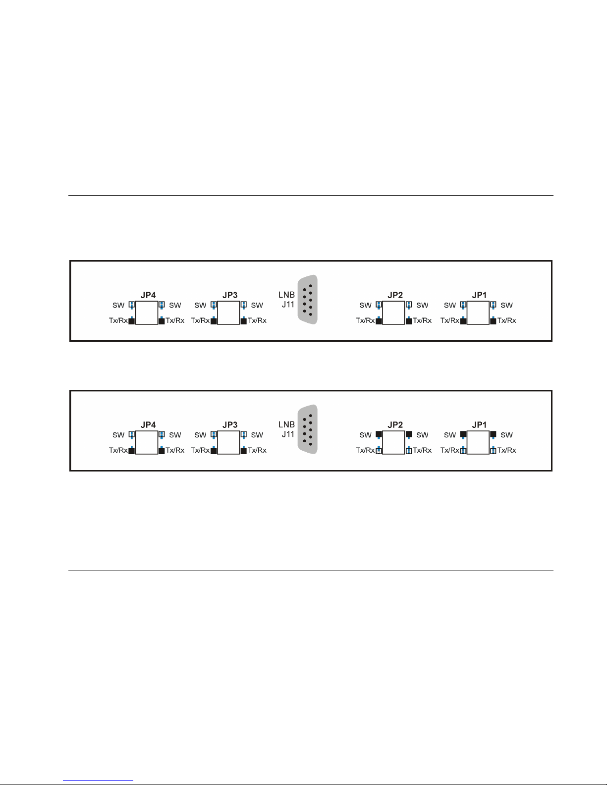
2. If the 7180M has Tx or Rx units only, place all jumpers on the lower two pins.
Figure 8 - Jumper Installation: Tx and Rx Only
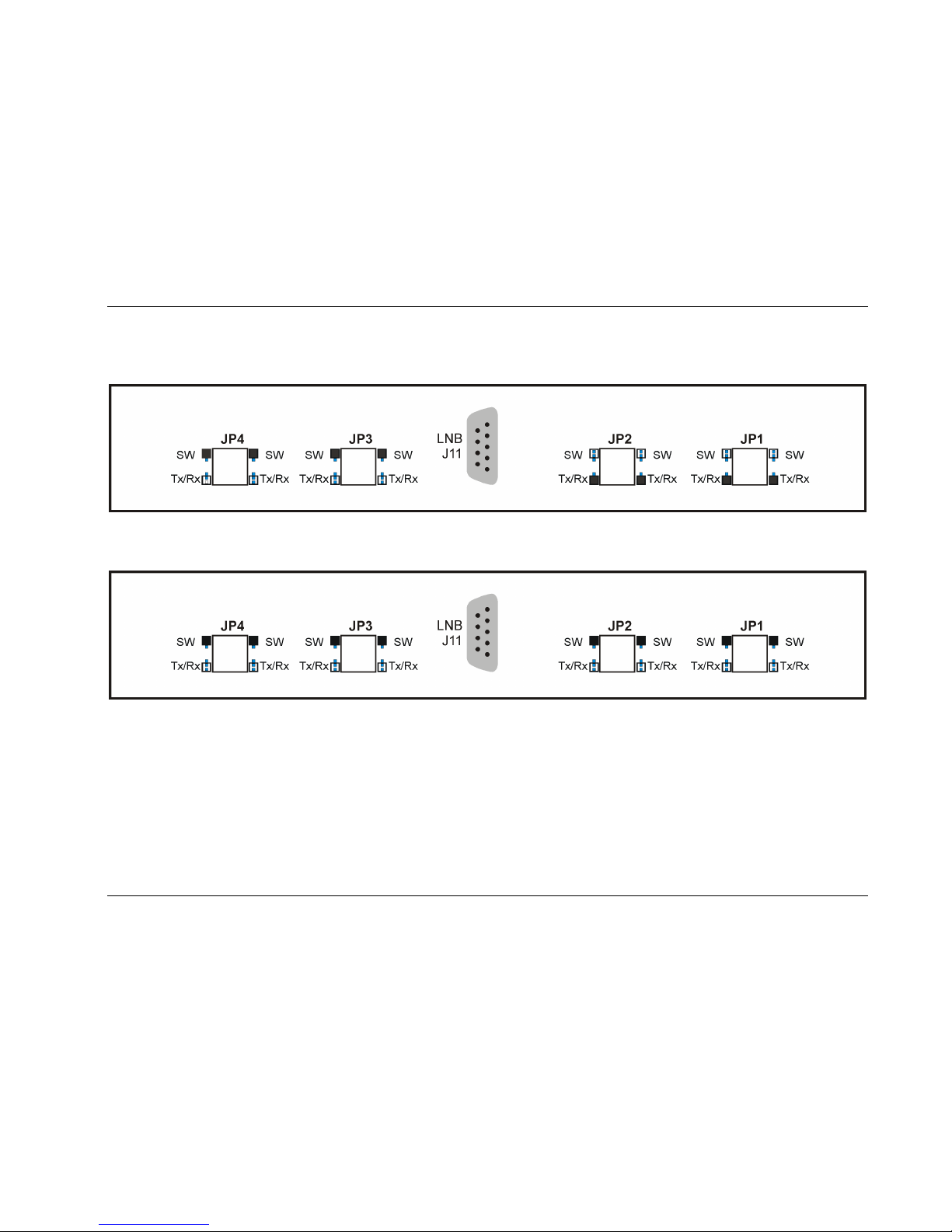
3. If the 2000 Switch is installed in Slot 2, place the JP1 and JP2 jumpers on the higher two pins and the JP3 and JP4
jumpers on the lower two pins.
Figure 9 - Jumper Installation: 2000 Switch in Slot 2
4. If the 2000 Switch is installed in Slot 5, place the JP1 and JP2 jumpers on the lower two pins and the JP3 and JP4
jumpers on the higher two pins.
7410F IFL Installation and Users Guide
Installation
Foxcom Proprietary Information 23
Document No. 93-006-01-A
Figure 10 - Jumper Installation: 2000 Switch in Slot 5
5. If the 2000 Switch is installed in Slots 2 and 5, place the JP1, JP2, JP3, and JP4 jumpers on the higher two pins.
Figure 11 - Jumper Installation: 2000 Switch in Slots 2 and 5
 Loading...