

Page 1
Fox Marine MEFI-1/2/3/4 Engine Gateway
Installation and Operating Instructions
Revised 05/29/21
Page 1 of 7
Thank you for your purchase of Fox Marine's MEFI Engine Gateway. The following details are provided
for installation and operating instructions. These instructions are intended for hardware shipped on or after
07/01/20. For older hardware, refer to the previous instruction revision.
NMEA 2000 Installation
Detailed NMEA 2000 (N2k) installation instructions should be provided by the manufacturer of your N2k
starter kit.
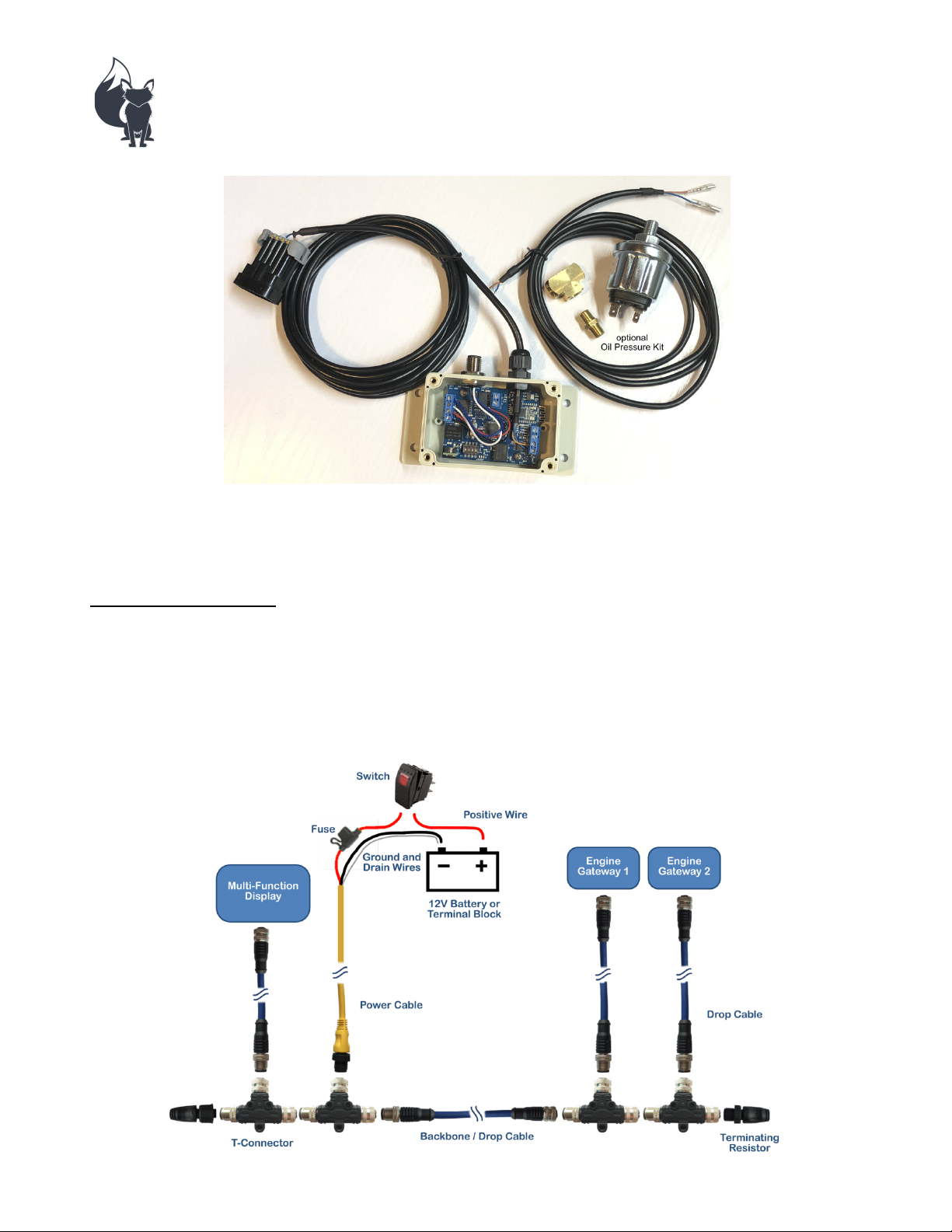
Reference the diagram below for a graphical representation of a basic N2k setup.
Page 2
Revised 05/29/21
Shared Data Connector
Shared Data Connector
Slave Ground
Page 2 of 7
The positive (red) lead from the power cable should contain a fuse and be connected to a switch of equal or
greater amperage rating. On single engine setups, N2k power can be connected to the ignition-key-on
circuit.
The negative (black) lead from the power cable should be connected with the drain (bare) wire at a suitable
ground source.
Fox Marine MEFI Engine Gateways receive power from the N2k bus. Switch your N2k bus off when not in
use.
Engine Gateway Installation
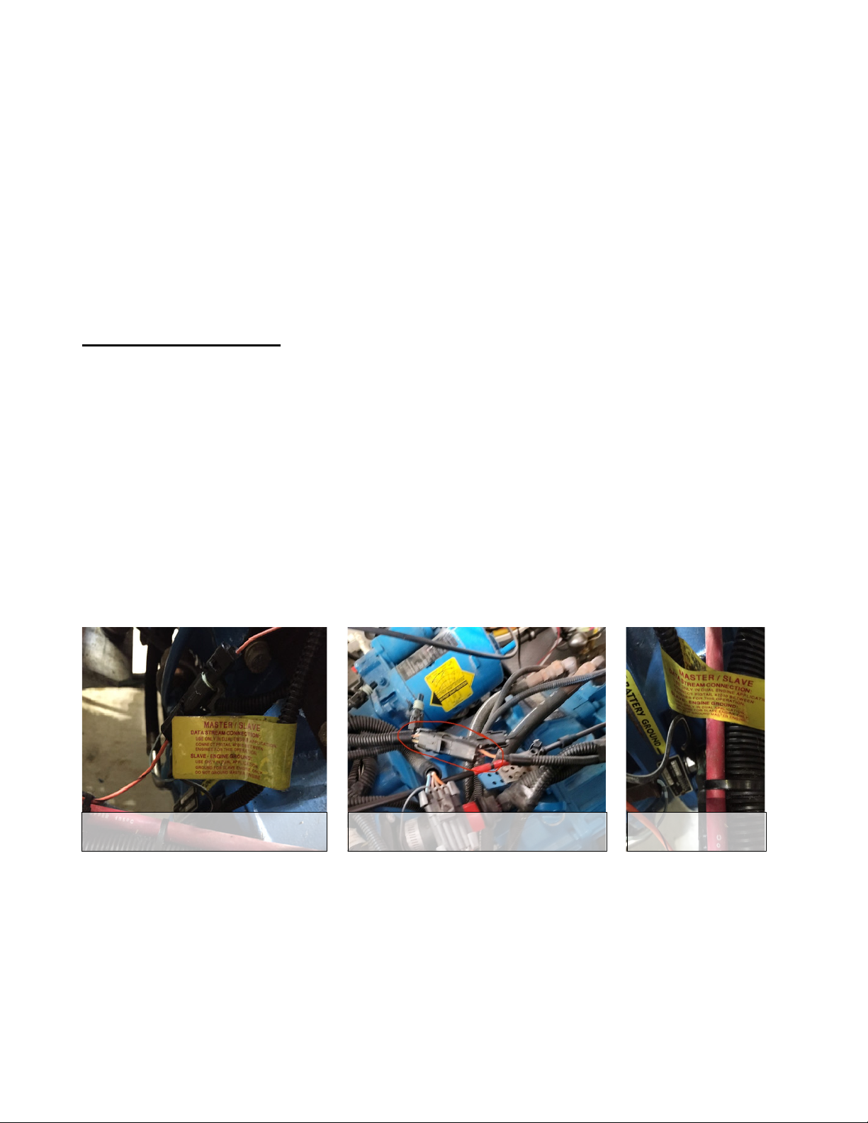
Certain dual engine setups share data between both engines through a single wire. The associated connector
must be unplugged to prevent data collisions while using Fox Marine MEFI Engine Gateways. Some
applications use a three-wire connector, others use a single-wire connector. This connector is usually found
in the engine wiring harness on the back of the engine (opposite of belts/pulleys) and contains an orange
wire with a black stripe.
These dual engine setups designate one engine as master and the other as slave. It is common for the
starboard engine to be master and the port as slave, but is not necessarily true for all applications. The
wiring harness on each engine may have a wire with labeling stating that it is to be grounded on the slave
engine and left disconnected on the master engine. Each Fox Marine MEFI Engine Gateway has a DIP
switch for master/slave that must be setup accordingly (DIP switch details below). If there is no common
data wire or master/slave grounding wire, than each engine will respond as master. Refer to the
troubleshooting section below after reading the entire manual for additional guidance on master/slave
setups.
Page 3

Revised 05/29/21
Page 3 of 7
Engine gateways that are purchased in pairs will be setup and labeled as Port and Starboard. If it is desired
to verify or change DIP switch positions, unscrew the 4 bolts to remove the lid of the engine gateway. DIP
switches are labeled 1, 2, 3, & 4 and have positions labeled OFF (down) and ON (up). Engine gateway
power should be off when changing DIP switch positions.
DIP switch 1 toggles between engine identifiers. OFF (down) designates the Engine Gateway as Port
(engine #1). ON (up) designates the Engine Gateway as Starboard (engine #2). We also support 3 and 4
engine applications when requested.
DIP switch 2 toggles between master/slave. See section above and troubleshooting section below for more
details. OFF (down) is used for master and single engine setups. ON (up) is used for slave.
DIP switch 3 allows or disables the ability to change gateway settings via bluetooth. Leave this switch OFF
(down) to allow bluetooth connection with the Fox Marine App to change gateway settings (such as alarm
throughput on the N2k network, fuel flow broadcast on the N2k network, RPM averaging, fuel flow scale
factor, clear engine codes). ON (up) disables the ability to change settings via bluetooth.
DIP switch 4 toggles normal/simulate mode. OFF (down) allows normal transmission of live engine data.
ON (up) enables the transmission of simulated engine data on the N2k network. Simulated data is not
transmitted via bluetooth.
Install the lid and proceed to mount the device as follows. The engine gateway is designed to be mounted in
the engine compartment away from excessive sources of heat and water. The enclosure is IP66 rated (dust
tight and water resistant to jet/spray). Ensure wires are routed away from sources of heat and rotating
equipment. Use zip ties as required.
If you purchased the optional Oil Pressure Kit, your engine gateway comes pre-programmed to read and
broadcast oil pressure. The software is optimized for the included oil pressure sending unit only. The
sending unit has two connection terminals labeled S and G.
Install the included oil pressure sending unit. An 1/8” pipe tee and pipe nipple is included to allow
installation at your existing oil pressure switch or gauge sending unit. Use pipe thread sealant or teflon tape.
Some Oil Pressure Kits have blue and brown wires. Some have red and black wires.
Connect the oil pressure data cable's blue or red wire to the S terminal.
Connect the brown or black wire to the G terminal.
Page 4
Revised 05/29/21
Protective Cap
Cap with Timing Tool
Page 4 of 7
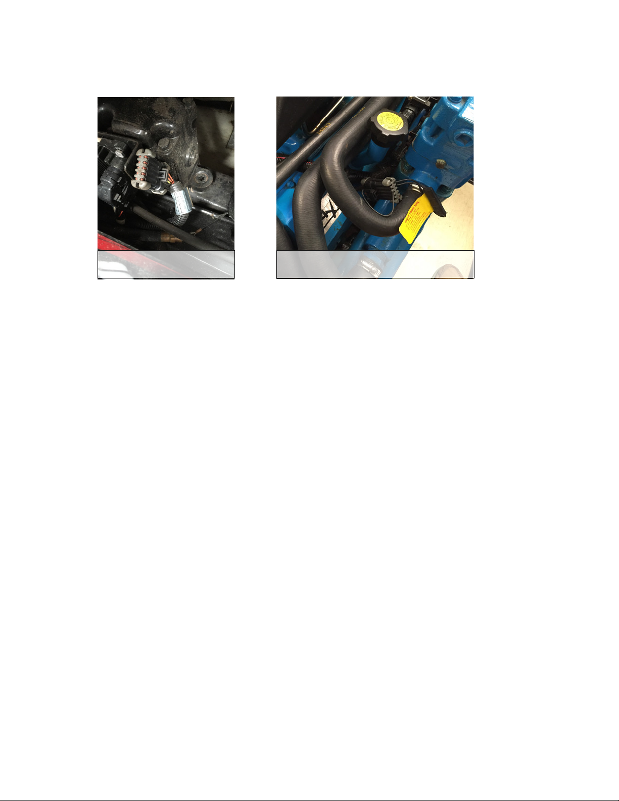
Plug the engine gateway into the boat's 10-pin diagnostic connector. This connector may already be plugged
in to a cap for protection. Some caps have a switch installed to allow for base timing adjustment.
Plug the engine gateway into the N2k network.
Page 5

Revised 05/29/21
Page 5 of 7
Operating Instructions
It is recommended to either key on your ignition(s) or fully start the engine(s) prior to turning on the N2k
bus power. This can be ignored if the N2k bus power is provided by the ignition circuit.
If the N2k bus power is turned on first, the MEFI ECM will not receive a notification when the engine
gateway powers up which may result in missed or sporadic data. The engine gateway will resubmit its
initial notification after several seconds if data is continuously missed.
Once communication has been established, live engine data will be broadcasted on the N2k bus and via
bluetooth. Engine RPM is broadcasted twice per second with the remaining data broadcasted once per
second. The Fox Marine iOS/Android app is available on Apple's App Store and Google's Play Store.
Instantaneous engine RPM is averaged with previous values to obtain a smoother RPM display. This allows
one to make fine throttle adjustments to match RPMs between two engines. The default setting averages 15
RPM values (i.e. 7.5 seconds of data). This setting can be changed from its default value using the iOS app
from a range of 1 (no averaging) to 30.
The engine gateway broadcasts the average RPM value on the N2k network only when the absolute
difference between the instantaneous RPM and the average RPM is less than a nominal value. When the
instantaneous RPM is outside of this band (during rapid acceleration and deceleration), the instantaneous
RPM value is broadcasted on the N2k network to prevent any delay in indicated RPM vs. actual.
Each N2k compatible GPS/Multifunction Display will have its own setup menus to obtain and view engine
data. Typically, you must adjust display settings to configure the number of engines on your boat before
data from the Starboard engine is available to be viewed. Display settings can be changed to adjust the
default units used for displaying engine parameters if desired.
The data broadcasted on the N2k network is as follows and may vary or have different meanings depending
on the model of ECM and unique manufacturer inputs and settings. For example, common Volvopenta
MEFI-3 ECMs trigger a low oil pressure alarm on either low oil pressure or high exhaust riser temperature.
Engine # (as determined by DIP switch), Engine RPM, Fuel Flow Rate, Coolant Temperature,
Alternator/Battery Voltage, Engine Run Hours, Throttle Position (Engine Load), Oil Pressure (with the
purchase and installation of the optional Oil Pressure Kit),
Active Alarms: General Warning 1 (MEFI-2/3/4), General Warning 2 (MEFI-2/3/4),
Low Fuel Pressure (MEFI-3/4), Engine Overheat (MEFI-1/2/3/4), Low Oil Pressure (MEFI-1/2/3/4), Low
Oil Level (MEFI-3/4), Low System Voltage (MEFI-2/3/4)
Data broadcasted via bluetooth is more extensive and is similar to what would be available to be seen on a
dealership diagnostic scanner. Active alarm codes can also be cleared using the Fox Marine iOS/Android
app.
Fuel flow rate is calculated internally by your ECM. The Fox Marine iOS/Android app can be used to
adjust the scaling of the broadcasted fuel flow rate to better reflect actual fuel usage if a deviation is
apparent.
Switch off your N2k bus when not in use as the engine gateway(s) will be consuming power (up to 80
milliamps each) while constantly trying to obtain/transmit engine data and bluetooth data.
Page 6

Revised 05/29/21
Page 6 of 7
Simple Troubleshooting
If RPM values are rounded to the nearest 25 rpm or some other standard value.
Some GPS/Multi-Function Displays round the RPM value to preset divisors. Consult the manufacturer of
your display for more details.
If single engine data is not displaying.
Ensure the engine gateway version matches the ecm MEFI version (MEFI-1/2/3/4). Refer to our FAQ page
to match GM/Delphi ecm numbers to a MEFI version. Most single engine setups are configured as master
(DIP Switch #2 OFF). If the setup is configured as slave, set DIP Switch #2 to ON. Contact Fox Marine for
additional troubleshooting details.
If twin engine data is missing or not displaying properly.
Ensure the port engine gateway has DIP Switch #1 OFF (down) and the starboard engine gateway has DIP
Switch #1 ON (up). If a common data wire exists between both engines, ensure it is unplugged per the
installation section above. Ensure DIP Switch #2 is properly set for master/slave. Ensure your GPS/MultiFunction Display is properly configured to expect to receive engine data from two engines. Consult the
manufacturer of your display for more details on display setup. Contact Fox Marine for additional
troubleshooting details.
If the master/slave setup is not known.
The following three sections should be followed to properly setup master/slave configuration for starboard
and port engines and to verify data collisions are not present due to a common data wire.
Establish master/slave configuration on the starboard engine:
1. Install only the starboard engine gateway with DIP Switch 1–ON, 2–OFF, 3–OFF, 4-OFF
2. Key on the starboard engine ignition (no need to start)
3. Turn on N2k network power
4. Open the Fox Marine iOS/Android app and connect to the starboard engine gateway
5. Raise the throttle on the starboard engine while observing the TPS response on the app
a. If the proper response is not observed, perform the following.
1. Position DIP Switch 2–ON (slave) on the starboard engine gateway
2. return to previous Step 5.
6. Key off the starboard engine ignition
7. Turn off N2k network power
Establish master/slave configuration on the port engine:
1. Unplug the N2k connector on the starboard engine gateway.
2. Install the port engine gateway with DIP Switch 1– OFF, 2– OFF, 3– OFF, 4- OFF
3. Key on the port engine ignition (no need to start)
4. Turn on N2k network power
5. Open the Fox Marine iOS/Android app and connect to the port engine gateway
6. Raise the throttle on the port engine while observing the TPS response on the app
a. If the proper response is not observed, perform the following.
1. Position DIP Switch 2–ON (slave) on the port engine gateway
2. return to previous Step 6.
7. Key off the port engine ignition
8. Turn off N2k network power
9. Plug in the N2k connector on the starboard engine gateway
Page 7

Revised 05/29/21
Page 7 of 7
The following steps help confirm there are no data collisions between the port and starboard engine
gateways due to a common data wire existing between both engines. This is only accurate after first
properly setting up the master/slave configurations.
1. Key on BOTH engine ignitions (no need to start)
2. Turn on N2k network power
3. Open the Fox Marine iOS/Android app and connect to the port engine gateway
4. Raise the throttle on the starboard engine and verify no TPS response on the app
a. If the starboard throttle was observed when viewing port engine data, then both engine ECM
data wires remain connected and will result in incorrect data displayed for both engines.
1. Disconnect the common data wire connecting both engine ECMs (single-wire or three-wire
connector is typical)
If the units for certain engine data is not preferred.
Changing the units for engine data is a function of your GPS/Multi-Function Display. Refer to your
GPS/Multi-Function Display settings or consult the manufacturer of your display for more details.
Please contact [email protected] with any questions/comments/concerns.
 Loading...