

Page 1
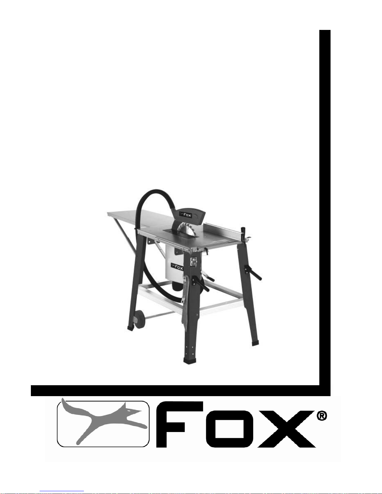
BANCO SEGA 315 mm
TABLE SAW 315 mm
Modello Fox F36-528
Fox model F36-528
MANUALE DI ISTRUZIONI / USER MANUAL
Page 2

2
SOMMARIO / INDEX
ITALIANO (IT) Manuale originale, Original manual 3÷24
ENGLISH (EN) Manuale tradotto dall’originale / Manual translated from the original 25÷46
DICHIARAZIONE DI CONFORMITA / DECLARATION OF CONFORMITY 47
ESPLOSO / EXPLODED VIEW 48
SCHEMA ELETTRICO / WIRING DIAGRAM 50
Page 3

3
Banco sega 315 mm (Modello F36-528)
SOMMARIO
• Sicurezza Pag. 4
• Regole generali di sicurezza Pag. 5
• Regole supplementari di sicurezza per le segatrici circolari Pag. 7
• Protezione dell’ambiente Pag. 9
• Simboli Pag. 9
• Collegamento alla corrente elettrica Pag. 10
• Uso conforme alle norme Pag. 11
• Caratteristiche tecniche Pag. 12
• Informazioni sul rumore Pag. 12
• Disimballo Pag. 13
• Descrizione del banco sega Pag. 14
• Montaggio Pag. 15
A. Montaggio del basamento della segatrice Pag. 15
B. Montaggio degli accessori della segatrice Pag. 16
C. Montaggio dell’estensione del piano di lavoro Pag. 16
D. Utilizzo delle ruote per lo spostamento Pag. 16
E. Montaggio / smontaggio della protezione della lama Pag. 16
• Regolazioni Pag. 17
A. Regolazione del coltello divisore Pag. 17
B. Sostituzione dell’inserto del piano di lavoro Pag. 18
C. Sostituzione della lama della sega Pag. 18
• Funzionamento Pag. 19
Premessa Pag. 19
A. Interruttore avvio / arresto Pag. 19
B. Protezione del motore Pag. 19
C. Frenatura della lama Pag. 20
D. Profondità di taglio Pag. 20
E. Guida parallela Pag. 20
F. Realizzazione dei tagli longitudinali Pag. 21
G. Taglio dei pezzi piccoli Pag. 21
H. Taglio obliquo Pag. 22
I. Taglio trasversale Pag. 22
J. Aspirazione della polvere Pag. 22
• Manutenzione Pag. 23
• Anomalie di funzionamento Pag. 23
• Assistenza Pag. 24
Page 4

4
ATTENZIONE:
Quando si utilizzano utensili elettrici si dovrebbero sempre rispettare, oltre a quelle riportate
in questo manuale, tutte le precauzioni base di sicurezza per ridurre il rischio di incendio,
scossa elettrica e danni personali.
Leggere attentamente tutte queste istruzioni prima di utilizzare questo prodotto e
conservarle scrupolosamente.
Le lavorazioni effettuate con un elettroutensile possono diventare pericolose per l’operatore
se non vengono rispettate norme operative sicure ed adeguate. Come per qualsiasi
macchina elettrica che ha un organo di lavoro in movimento, l’utilizzo dell’utensile comporta
alcuni rischi. Se la macchina viene utilizzata come indicato su questo manuale, prestando la
massima attenzione al lavoro che si sta facendo, rispettando le regole ed utilizzando gli
adeguati dispositivi di protezione individuali, la probabilità di incidenti sarà quasi nulla. I
possibili rischi residui sono relativi a:
1 – contatti diretti od indiretti con la scossa elettrica
2 – ferimenti per contatto con parti rotanti in movimento
3 – ferimenti per contatto con parti spigolose
4 – ferimenti per eiezioni di parti di utensile o di materiale in lavorazione
5 – danni causati dal rumore
6 – danni causati dall’inalazione di polveri pericolose
7 – ferimenti per utensili montati male
Le attrezzature di sicurezza previste sulle macchine, come le protezioni, i carter, gli
spingipezzo, i dispositivi di ritenuta, i dispositivi di protezione individuale come gli occhiali, le
maschere antipolvere, le protezioni auricolari, le scarpe e i guanti possono ridurre le
probabilità di incidente. Anche la migliore protezione, però, non può proteggere contro la
mancanza di buon senso e di attenzione. Abbiate sempre buon senso e prendete le
precauzioni necessarie. Fate solo i lavori che ritenete siano sicuri. NON DIMENTICATE: la
sicurezza è responsabilità di ognuno.
Questo utensile è stato concepito per un utilizzo ben preciso. DELTA France raccomanda di
non modificarlo o di non utilizzarlo per scopi diversi rispetto a quelli per cui è stato costruito.
Se avete dei dubbi relativamente ad applicazioni specifiche, NON utilizzate l’utensile prima di
aver contattato DELTA France e aver ricevuto informazioni in merito.
LEGGETE E CONSERVATE QUESTO MANUALE
SICUREZZA
Page 5

5
1. Mantenete l’area di lavoro pulita. Nelle zone o nei banchi di lavoro ingombri è più alta
la probabilità di incidenti.
2. Evitate un ambiente pericoloso. Non esponete gli utensili alla pioggia e non utilizzateli
in ambienti umidi o bagnati, per evitare i fenomeni di elettrolocuzione. Mantenete la
zona di lavoro ben illuminata. Non utilizzate l’utensile in presenza di gas o di liquidi
infiammabili.
3. Collegate il dispositivo di aspirazione della polvere. Se sono previsti dei metodi per il
recupero della polvere, assicuratevi che questi dispositivi siano collegati e utilizzati
correttamente.
4. Tenete gli estranei e i bambini lontani. Tutti gli estranei e i bambini devono mantenere
una distanza di sicurezza dall’area di lavoro.
5. Proteggetevi dalle scariche elettriche. Evitate di entrare in contatto con delle superfici
di messa a terra.
6. Non maltrattate il cavo elettrico. Non tirate mai il filo elettrico per scollegarlo dalla
presa. Mantenete il cavo elettrico lontano dal calore, dall’olio e dagli spigoli vivi.
7. Utilizzate delle prolunghe elettriche previste per l’esterno. Quando l’utensile viene
utilizzato all’esterno, utilizzate solamente delle prolunghe elettriche previste per
l’esterno e che riportino delle indicazioni in merito.
8. Siate vigili. Osservate attentamente quello che fate, abbiate buon senso. Non utilizzate
l’utensile quando siete affaticati.
9. Non utilizzate l’utensile se siete sotto l’effetto di medicinali, alcol, droghe.
10. Evitate l’avvio accidentale. Assicuratevi che l’interruttore sia nella posizione di arresto
prima di collegare l’utensile.
11. Indossate una tenuta appropriata. Non indossate vestiti ampi o gioielli che possono
impigliarsi nei pezzi mobili. Per il lavoro all’esterno sono particolarmente raccomandate
le scarpe antiscivolo. Portate un mezzo di protezione per i capelli lunghi.
12. Usate sempre i dispositivi di protezione personale: portate gli occhiali di sicurezza
e le mascherine nei casi in cui si producano polveri o trucioli. Indossate cuffie
antirumore o tappi protettivi in ambienti rumorosi. Usate guanti quando si maneggiano
particolari con spigoli vivi e taglienti.
13. Non sbilanciatevi sopra all’utensile. Mantenete sempre il vostro equilibrio.
14. Chiedete consigli a persone esperte e competenti se non avete familiarità con il
funzionamento dell’utensile.
15. Allontanate gli utensili inutilizzati. Quando gli utensili non vengono utilizzati, devono
essere sistemati in un luogo secco, chiuso a chiave, fuori dalla portata dei bambini.
REGOLE GENERALI DI SICUREZZA
Page 6

6
16. Non forzate l’utensile. La lavorazione sarà migliore e maggiormente sicura se l’utensile
viene utilizzato al ritmo per il quale è stato concepito.
17. Utilizzate l’utensile appropriato. Non forzate un piccolo utensile a fare il lavoro di un
utensile a utilizzo intensivo. Per esempio, non utilizzate una sega circolare per tagliare
dei rami o dei ceppi.
18. Fissate il pezzo. Utilizzate per quanto possibile dei morsetti a vite o una morsa per
bloccare il pezzo. E’ più sicuro che servirsi delle sole mani.
19. Mantenete gli utensili in perfetto stato. Tenete gli utensili affilati e puliti in modo da
ottenere un rendimento migliore e più sicuro. Seguite le istruzioni per lubrificare e
sostituire gli accessori. Controllate regolarmente il cavo elettrico e sostituitelo se è
danneggiato. Tenete le maniglie e le impugnature secche, pulite e prive di olio e di
grasso.
20. Scollegate l’utensile dalla rete quando non è utilizzato, prima della manutenzione e
della sostituzione degli accessori o utensili quali lame, punte, frese, ecc.
21. Allontanate le chiavi di serraggio e di regolazione. Prendete l’abitudine di verificare che
le chiavi di serraggio e di regolazione siano state allontanate dall’utensile prima di
avviarlo.
22. Controllate i particolari dell’utensile per verificare che non ci siano parti danneggiate.
Prima di continuare ad utilizzare l’utensile, controllate tutti i dispositivi di sicurezza o
qualsiasi altro pezzo che possa essere danneggiato in modo da assicurarvi che funzioni
bene e che riesca ad effettuare il compito previsto. Verificate che i pezzi mobili siano
ben allineati, non si blocchino e non siano rotti. Controllate anche il montaggio o
qualsiasi altra condizione che può influenzare il funzionamento. Qualsiasi pezzo o
qualsiasi protezione danneggiata deve essere riparata o sostituita da un centro di
servizio post-vendita autorizzato. Non utilizzate l’utensile se l’interruttore non funziona
correttamente.
23. Utilizzate l’elettroutensile, gli utensili e gli accessori nel modo e per gli sco pi riportati in
questo manuale; utilizzi e componenti diversi possono generare possibili rischi per
l’operatore.
24. Fate riparare l’utensile da una persona competente. Questo utensile elettrico è
conforme alle prescrizioni di sicurezza corrispondenti. Le riparazioni devono essere
realizzate solo da persone qualificate che utilizzino ricambi originali, altrimenti
potrebbero insorgere dei pericoli per l’utilizzatore.
Page 7

7
1. NON AVVIATE la sega finché non è completamente assemblata e installata secondo le
direttive del presente manuale.
2. UTILIZZATE sempre la protezione lama, il coltello divisore e lo spingipezzo per “tagliare
completamente”. Con questa espressione si intende “tagliare interamente” il pezzo in
tutto il suo spessore.
3. TENETE sempre il pezzo ben appoggiato alla guida obliqua o alla guida di taglio
parallela.
4. UTILIZZATE sempre uno spingipezzo per fare avanzare il legno oltre la lama e in
particolare per tagliare i pezzi piccoli. Per dettagli più specifici sullo spingipezzo, vedere
le sezioni sul taglio in lungo in queste istruzioni.
5. NON LAVORATE mai a “mano libera”. Utilizzate sempre la guida obliqua o la guida di
taglio parallela per posizionare e guidare il pezzo da tagliare.
6. NON POSIZIONATEVI mai nell’asse della lama. TENETE le mani distanti dalla
traiettoria della lama.
7. NON PASSATE mai le mani dietro o sopra la lama ed evitate di assumere posizioni
scomode con le mani e il corpo.
8. ALLONTANATE la guida di taglio parallela durante il taglio trasversale.
9. NON UTILIZZATE MAI la guida di taglio parallela come guida di tranciatura per il taglio
trasversale.
10. FATE sempre avanzare il pezzo da tagliare contro la lama o l’utensile.
11. NON TENTATE MAI di sbloccare la lama senza prima arrestare l’utensile. Anche se
volete interrompere il taglio, mettete l’interruttore in posizione di arresto e aspettate che
la lama si fermi. Intervenite solo con lama ferma e in mancanza di alimentazione
elettrica.
12. EVITATE di togliere pezzi di legno incastrati tra lama e asola con la lama in movimento.
Spegnete la macchina e aspettate che la lama si fermi, poi intervenite.
13. APPOGGIATE su dei cavalletti le estremità dei grandi pezzi che fuoriescono
lateralmente o posteriormente dal banco della sega.
14. EVITATE gli arretramenti violenti (pezzo che viene proiettato verso se stesso):
A. lavorando sempre con una lama ben affilata e adatta al materiale da tagliare;
B. controllando il parallelismo tra la guida e la lama;
C. utilizzando sempre il coltello divisore, lo spingipezzo e la protezione della lama;
D. non rilasciando il pezzo fino a quando non sia completamente tagliato;
E. evitando pezzi storti o deformati che non hanno un lato rettilineo che permette di
farli avanzare uniformemente lungo la guida.
REGOLE DI SICUREZZA GENERALI PER LE SEGHE CIRCOLARI
Page 8

8
15. NON UTILIZZATE mai dei solventi per pulire i pezzi in plastica. I solventi possono
sciogliere o danneggiare il materiale. Utilizzate solamente uno straccio umido per pulire
i pezzi in plastica.
16. INSTALLATE la sega in maniera PERMANENTE su una superficie in piano prima di
utilizzarla.
17. NON TAGLIATE mai dei metalli o dei materiali che possano produrre della polvere
pericolosa.
18. UTILIZZATE sempre il banco sega in un ambiente ben areato. Eliminate
frequentemente la segatura. Rimuovete bene la segatura che si trova all’interno della
sega per evitare il rischio di incendio.
19. NON UTILIZZATE delle lame danneggiate o deformate o lame in acciaio rapido ad alta
lega ( tipo HSS ).
20. UTILIZZATE solamente delle lame raccomandate dal fabbricante, conformi alla norma
EN 847-1.
21. UTILIZZATE lame adatte al materiale da tagliare e che abbiano marcata una velocità
maggiore di quella della macchina. Quando si sostituisce la lama, verificare che il
diametro esterno e il diametro del foro siano giusti, che la larghezza del taglio della
lama non sia inferiore allo spessore del coltello divisore e che lo spessore del corpo
lama non sia superiore a quella del coltello divisore. Trasportate sempre la lama
all’interno della sua custodia.
22. SOSTITUITE l’inserto in plastica posto sul piano attorno alla lama, quando è usurato o
danneggiato.
23. UTILIZZATE questo banco sega solamente per tagliare il legno e materiali simili.
24. CONTROLLATE regolarmente se il cavo di alimentazione è danneggiato, nel qual caso
fatelo riparare da un centro servizio post-vendita autorizzato. Controllate regolarmente
le prolunghe e sostituitele se sono danneggiate.
25. COLLEGATE un sistema di estrazione della polvere ed USATE protettori acustici e
mascherina antipolvere.
Page 9
9
INFORMAZIONE AGLI UTENTI
Ai sensi dell’art. 13 del Decreto Legislativo 25 luglio 2005, n. 151 “Attuazione delle Direttive
2002/95/CE, 2002/96/CE, e 2003/108/CE, relative alla riduzione dell’uso di sostanze
pericolose nelle apparecchiature elettriche ed elettroniche, nonché allo smaltimento dei
rifiuti”, si precisa quanto segue:
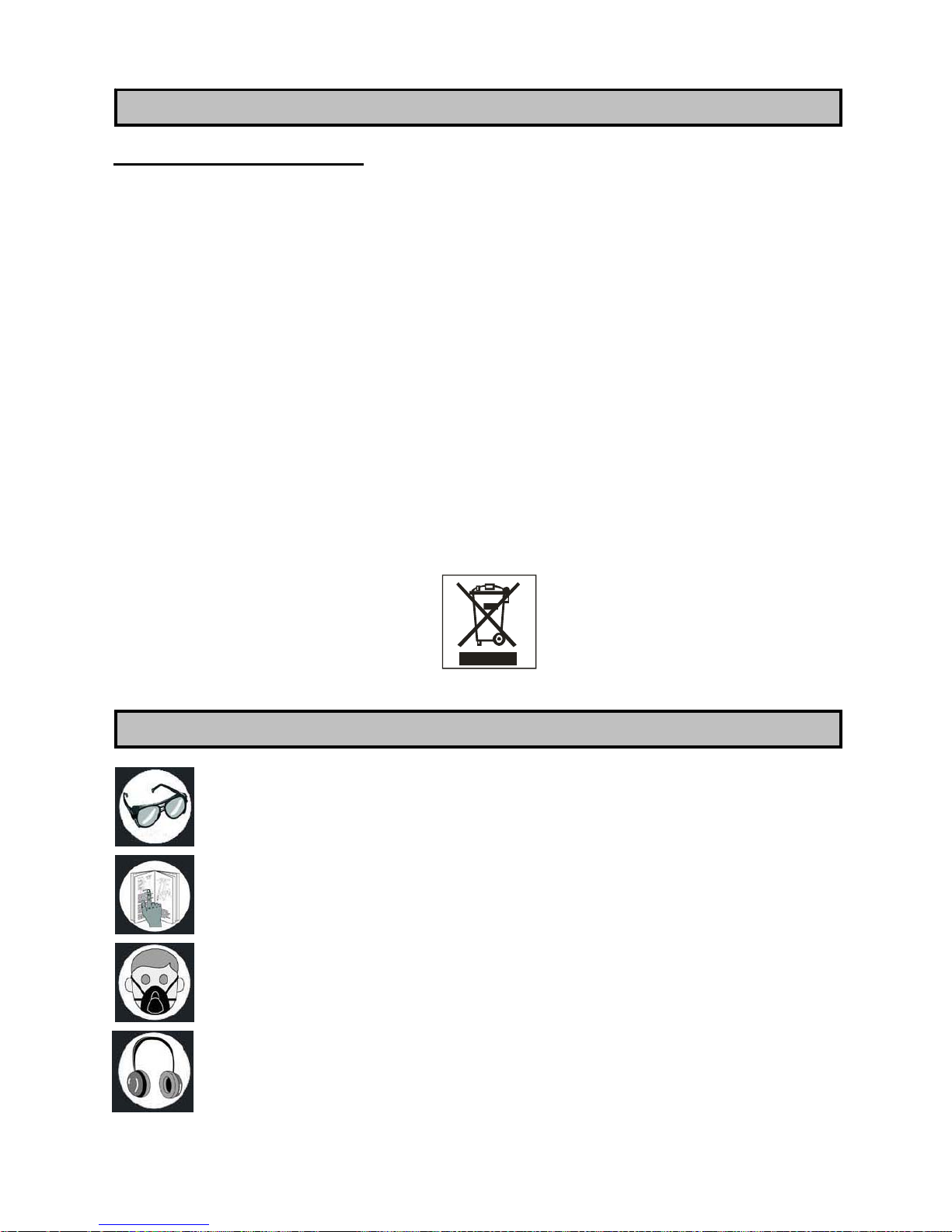
• Il simbolo del cassonetto barrato riportato sull’apparecchiatura o sulla confezione
indica che il prodotto alla fine della propria vita utile deve essere raccolto
separatamente dagli altri rifiuti.
• L’utente dovrà, pertanto, conferire l’apparecchiatura giunta a fine vita agli idonei centr i
di raccolta differenziata dei rifiuti elettronici ed elettrotecnici, oppure riconsegnarla al
rivenditore al momento dell’ acquisto di una nuova apparecchiatura di tipo equivalente,
in ragione di uno ad uno.
• L’adeguata raccolta differenziata per l’avvio successivo dell’apparecchiatura dismessa
al riciclaggio, al trattamento ed allo smaltimento ambientalmente compatibile,
contribuisce ad evitare possibili effetti negativi sull’ambiente e sulla salute e favorisce il
reimpiego e/o riciclo dei materiali di cui è composta l’apparecchiatura.
ATTENZIONE!
Lo smaltimento abusivo del prodotto da parte dell’utente comporta l’applicazione delle
sanzioni amministrative previste dalla normativa vigente.
Indossate sempre degli occhiali di protezione.
Leggete con attenzione il manuale di istruzioni prima di utilizzare la macchina.
Portare sempre una maschera di protezione contro la polvere.
Indossate sempre una cuffia per proteggervi dal rumore.
PROTEZIONE DELL’AMBIENTE
SIMBOLI
Page 10
10
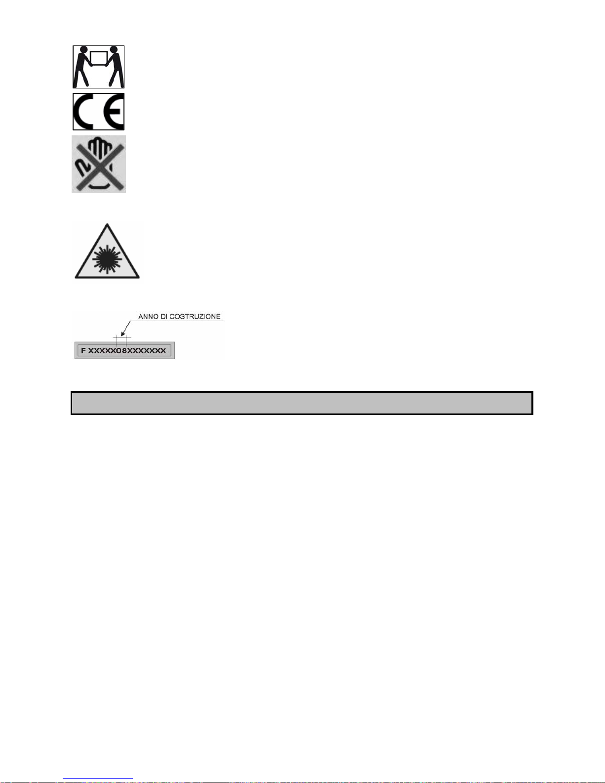
Imballaggio pesante. Il trasporto della macchina richiede due persone.
Prodotto conforme alle norme relative della CE.
E’ vietato inserire le mani in questa zona, utensile in funzione. Pericolo di
trascinamento/taglio.
Indica il servizio sull’ utensile di un puntatore laser (vedi paragrafo REGOLE
DI SICUREZZA PER IL PUNTATORE LASER)
Matricola / anno produzione
COLLEGAMENTO ELETTRICO
Per l’alimentazione della vostra macchina è necessaria una tensione alternata a 230 V 50 Hz
con conduttore di terra. Assicuratevi che la vostra alimentazione abbia queste caratteristiche,
che sia protetta da un interruttore differenziale e magnetotermico e che l’impianto di terra sia
efficiente. Se la vostra macchina non funziona quando è collegata ad una presa, verificate
attentamente le caratteristiche dell’alimentazione.
Per collegarla alla corrente serve una prolunga in quanto la sega è dotata di un gruppo spina,
ma non di un cavo elettrico.
ISTRUZIONI PER LA MESSA A TERRA
In caso di cattivo funzionamento o di corto circuito dell’utensile, la messa a terra fornisce un
cammino di minore resistenza alla corrente elettrica e riduce il rischio di scarica elettrica.
Questo utensile ha una spina, alla quale deve essere collegato un cavo di alimentazione o
una prolunga che a sua volta deve essere collegato ad una presa correttamente installata e
messa a terra in conformità alle normative e disposizioni locali. Assicuratevi della bontà del
vostro impianto di terra e che la vostra presa sia protetta a monte da un interruttore
differenziale e magnetotermico.
Un collegamento mal fatto del conduttore della messa a terra dell’attrezzo può comportare il
rischio di scarica elettrica. Il conduttore la cui guaina isolante è verde con o senza linea gialla
è il conduttore della messa a terra.
COLLEGAMENTO DELL’UTENSILE ALLA CORRENTE
Page 11
11
Informatevi presso un elettricista qualificato o da una persona responsabile della
manutenzione se non avete compreso o avete qualche dubbio sulle istruzioni della messa a
terra.
Se il cavo di alimentazione è danneggiato deve essere sostituito da personale qualificato.
Non fate funzionare l’utensile se il cavo di alimentazione è danneggiato.
PROLUNGHE
Utilizzate solamente delle prolunghe a tre conduttori con una spina a 2 spinotti e contatto di
terra e delle prese a due cavità e una terra corrispondenti alla presa dell’utensile. Quando
utilizzate un utensile elettrico ad una distanza apprezzabile dall’alimentazione, assicuratevi di
utilizzare una prolunga che abbia dimensioni sufficienti per trasportare la corrente di cui
l’utensile ha bisogno. Una prolunga sottodimensionata provocherebbe una caduta di tensione
nella linea comportando un surriscaldamento e una perdita di potenza. Possono essere
utilizzate solamente delle prolunghe che rispondono alle norme CE.
Lunghezza della prolunga: fino a 15 m
Dimensioni del filo: 3 x 2,5 mm²
Prima di utilizzare qualsiasi prolunga, verificate che non abbia dei fili scoperti e che l’isolante
non sia tagliato o usurato. Riparate o sostituite immediatamente la prolunga danneggiata o
usurata.
ATTENZIONE:
Le prolunghe devono essere sistemate fuori dalla zona di lavoro per evitare che possano
entrare in contatto con i pezzi in lavoro, l’utensile o altri particolari della macchina e creare
possibili rischi.
ATTENZIONE:
TENETE GLI UTENSILI E LE ATTREZZATURE FUORI DALLA PORTATA DEI BAMBINI
Questa macchina è stata concepita esclusivamente per le lavorazioni di rifilatura e taglio del
legno fino a 83 mm di spessore con la lama diritta e fino a 60 mm con lama inclinata di 45 °.
La macchina è dotata di sufficiente stabilità, ma ha comunque la possibilità, in caso di
necessità, di essere fissata al suolo.
LIMITI DI UTILIZZO
NON tagliate del legno con uno spessore superiore agli 83 mm
NON tagliate il metallo, la pietra, la gomma, la plastica, il gesso, la lana di vetro, ecc.
NON tagliate ceppi o pezzi di legno di forma irregolare.
NON montate altri utensili o lame diverse da quelle previste
NON utilizzate come una macchina portatile o una macchina non fissata.
NON modificate la macchina, i dispositivi di sicurezza, i protettori o gli interruttori.
USO CONFORME ALLE NORME
Page 12
12
NON utilizzate questa sega per fare delle scanalature cieche.
NON utilizzate per eseguire intagli o scanalature.
NON utilizzate in nessun modo la macchina senza protezione o senza i dispositivi di
sicurezza.
Potenza motore: 1800 W
Tensione di alimentazione e frequenza: 230 V - 50 Hz
Servizio: S2 20%
Velocità: 2860 min¯¹
Diametro della lama: 315 mm
Alesaggio della lama: 30 mm
Spessore corpo lama montato: 1,8 mm
Larghezza di taglio lama montata: 2,8 mm
Spessore del coltello e larghezza asola: 2,5 mm – 13 mm
Dimensioni del piano di lavoro: 800 x 550 mm
Dimensioni dell’estensione: 800 x 400 mm
Altezza di taglio a 90°: 83 mm
Altezza massima di taglio a 45°: 60 mm
Inclinazione della lama: 0 - 45 °
Attacco aspirazione: 100 mm
Dimensioni dell’imballo: 825 mm x 590 mm x 435 mm
Peso: 52 kg
Il rumore emesso, misurato conformemente alle norme EN18470, EN3744 e EN11201 è
risultato essere:
- Livello di pressione acustica
LpA = 83,2 dB(A) a vuoto e 94 dB(A) in lavoro
- Livello di potenza sonora
LWA = 96,1 dB(A) a vuoto e 108,7 dB(A) in lavoro
- Incertezza della misura K = 3 dB
Si consiglia di indossare adeguati protettori acustici.
Le sorgenti del rumore della sega sono: il motore elettrico e la sua ventilazione, la lama e
ovviamente il materiale da tagliare.
Per il motore e la sua ventilazione si consiglia di tenerlo controllato e di pulire i passaggi
dell’aspirazione, per le lame di utilizzare tipi silenziati e di tenerle sempre in perfetta
efficienza e per il materiale da tagliare di usare le lame giuste e di tenere sempre ben bloccati
i particolari da tagliare.
I valori indicati per il rumore sono livelli di emissione e non necessariamente livelli di lavoro
sicuro. Mentre vi è una correlazione tra livelli di emissione e livelli di esposizione, questa non
può essere usata con sicurezza per determinare se siano richieste o no ulteriori precauzioni.
I fattori che influenzano il reale livello di esposizione del lavoratore includono la durata
dell’esposizione, le caratteristiche dell’ambiente, altre sorgenti di rumore, per esempio il
numero di macchine e altre lavorazioni adiacenti. Inoltre i livelli di esposizione possono
variare da un Paese a Paese. Queste informazioni mettono comunque in grado l’utilizzatore
della macchina di fare la miglior valutazione dei pericoli e dei rischi.
CARATTERISTICHE TECNICHE
INFORMAZIONI SUL RUMORE
Page 13
13
Il vostro nuovo banco sega è consegnato completo in una scatola.
Togliere la sega e tutti i vari componenti dall’imballo, verificare che non manchi nulla e che
non ci sia niente di danneggiato.
Nel caso fossero presenti parti difettose o rovinate non utilizzarle per non compromettere
l’efficienza e la sicurezza dell’utensile. Rivolgersi ad un centro assistenza autorizzato per la
sostituzione dei particolari difettosi.
Per rendere perfettamente funzionante il banco sega devono essere montati vari particolari,
per i quali viene data una dettagliata spiegazione nel seguito.
Si consiglia di leggere attentamente le istruzioni di montaggio e di seguirle alla lettere.
Togliere eventuali protezioni con un detergente tipo WD40. Non utilizzare benzina o diluenti
per vernici.
La macchina, una volta montata, deve essere deve essere posizionata, per il suo utilizzo, su
una superficie perfettamente livellata, in un ambiente coperto, pulito, sgombro, ben aerato e
con un livello di illuminamento medio.
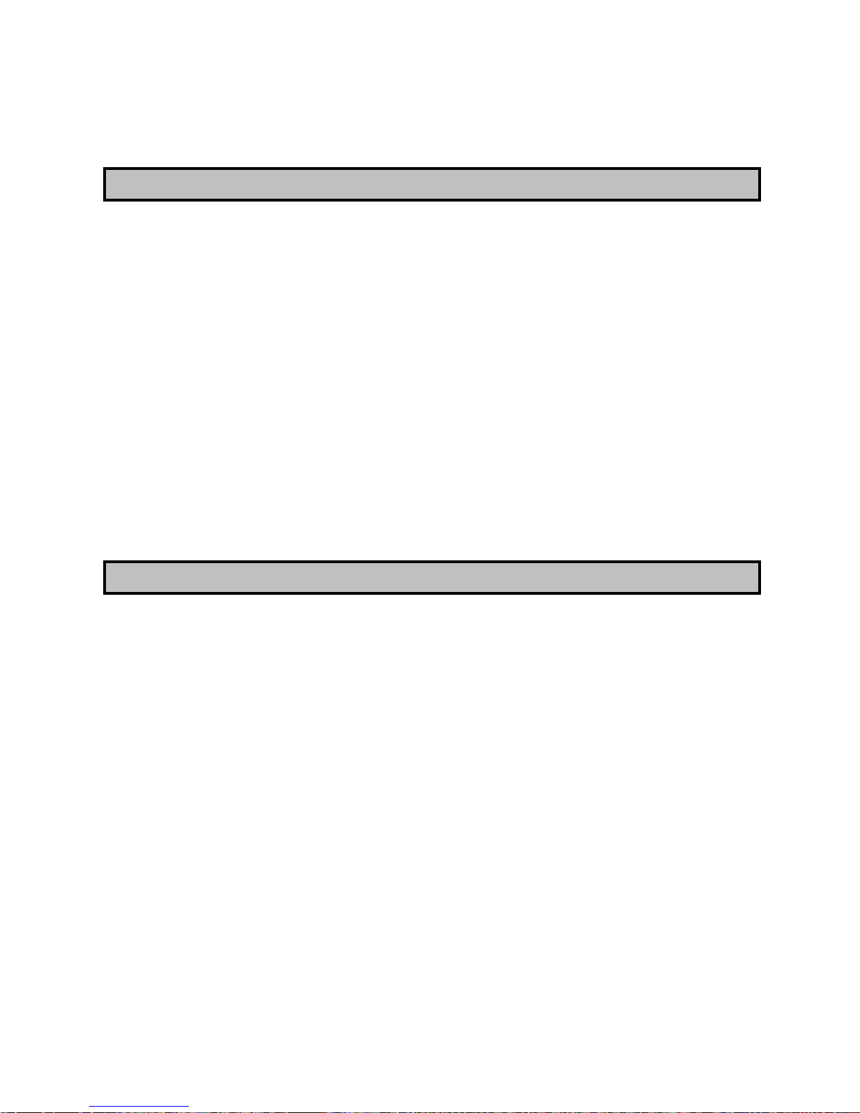
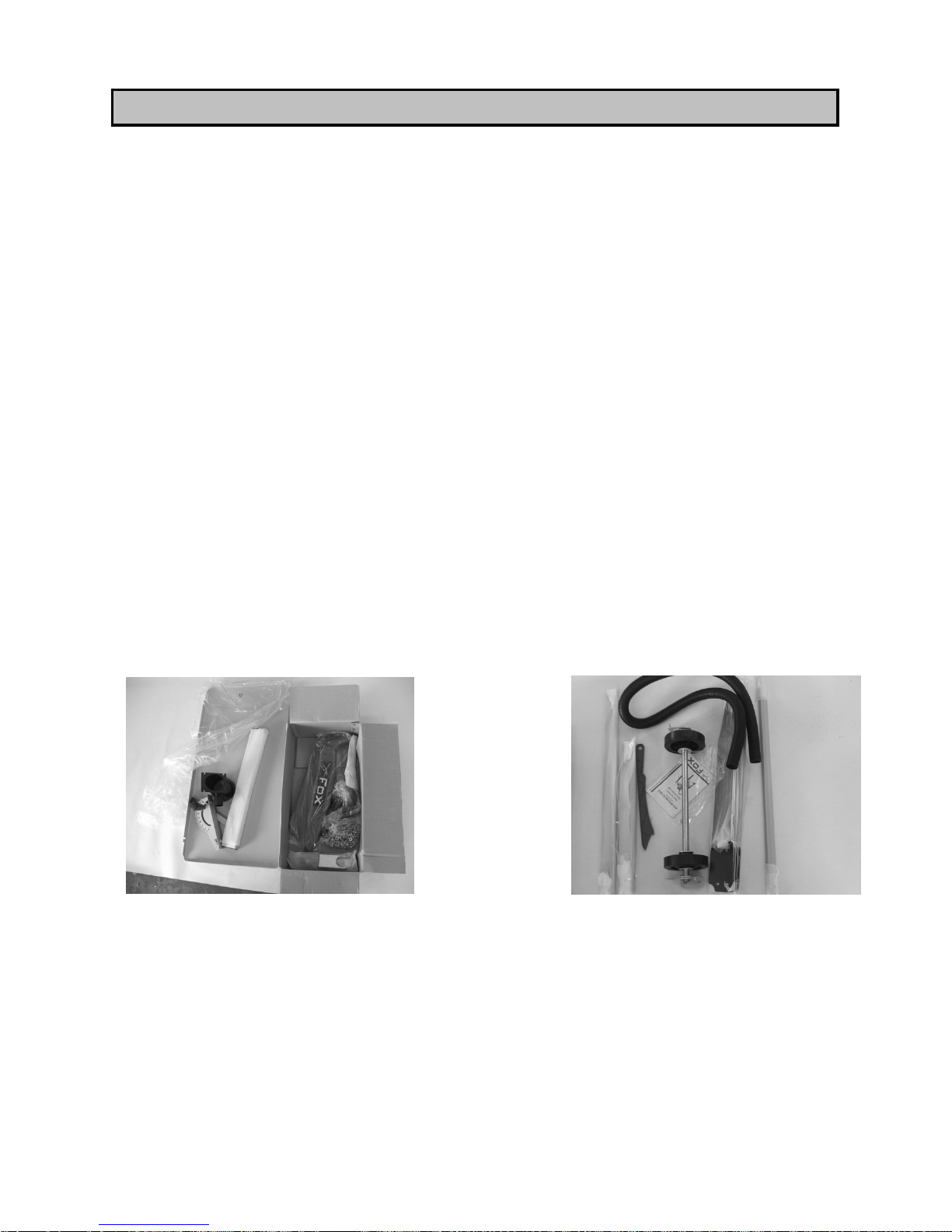
Nelle foto seguenti sono illustrati i componenti presenti nell’imballo oltre al corpo centrale
della macchina.
1 – N°2 Supporti estensioni 8 – N°1 Guida parallela/goniometro
2 – N°1 Tubo aspirazione 9 – N°1 Bocchetta aspirazione
3 – N°1 Gruppo ruote 10 – N°1 Protezione superiore
4 – N°4 Piedi + N°4 Gommini 11 – Viti e Rondelle
5 – N°2 Traverse Corte 12 – N°2 Chiavi per montaggio lama
6 – N°2 Traverse Lunghe 13 – N°1 Porta tubo aspirazione
7 – N°1 Spingilegno 14 – N°2 Maniglie
DISIMBALLO
Page 14
14
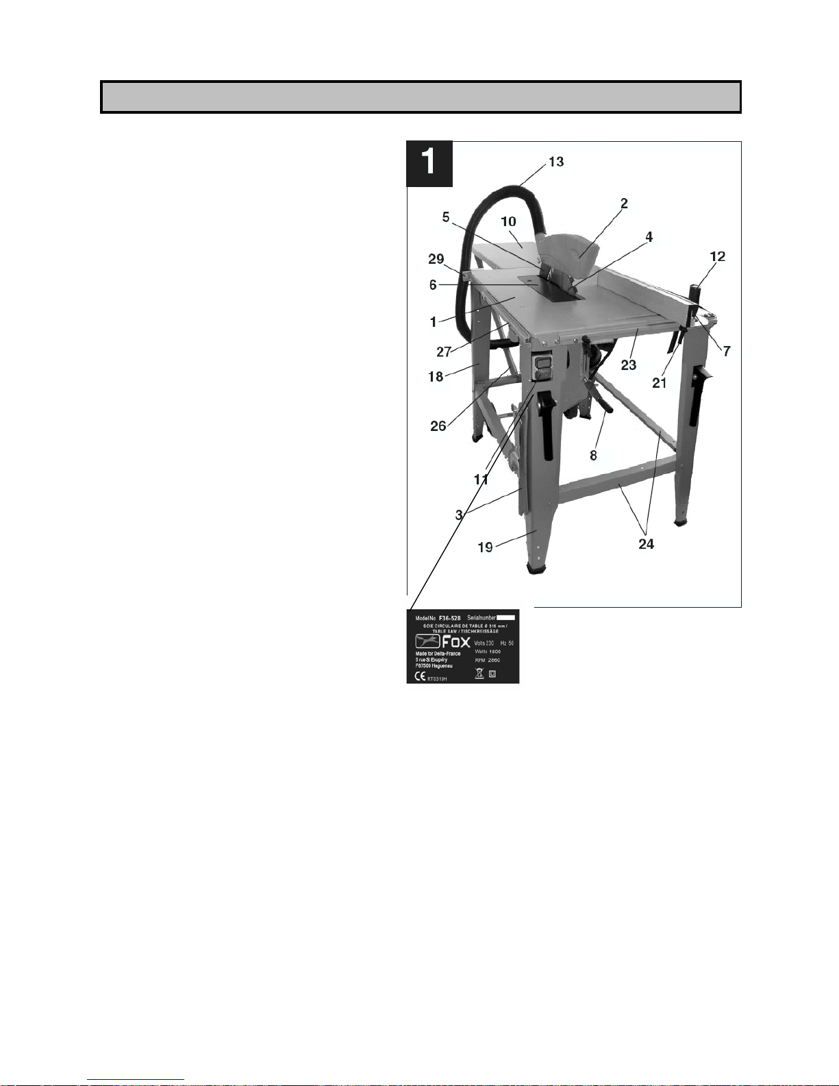
1. Piano di lavoro
2. Protezione della lama
3. Spingipezzo
4. Lama della segatrice
5. Coltello divisore
6. Inserto della tavola
7. Guida parallela e goniometro
8. Manovella di regolazione dell’altezza
della lama
9. Volantino di regolazione
dell’inclinazione della lama (Fig. 13)
10. Estensione posteriore del piano di
lavoro
11. Interruttore avvio / arresto
12. Impugnatura di bloccaggio del
goniometro
13. Tubo flessibile d’aspirazione
14. Manicotto d’aspirazione Ø 100 mm
(Fig. 2)
15. Supporto delle ruote per il trasporto
(Fig. 2)
16. Maniglia di spostamento (Fig. 2)
17. Raccogli segatura (Fig. 2)
18. Basamento della segatrice
19. Piede
21. Leva di bloccaggio della guida
parallela
22. Piastre di fissaggio delle ruote per il trasporto (Fig. 4)
23. Binario di scorrimento della guida parallela
24. Rinforzi dei piedi
25. Piedini in gomma (Fig. 2 )
26. Supporti dell’estensione posteriore del piano di lavoro
27. Binario di scorrimento della guida
28. Gancio portachiavi e porta spingipezzo (Fig. 6)
29. Supporto del tubo di aspirazione (Fig. 5)
30. Motore (Fig. 2)
DESCRIZIONE DEL BANCO SEGA
Page 15
15
ATTENZIONE!
Assicuratevi che la sega sia spenta e scollegata da ogni sorgente di corrente prima di
procedere al montaggio o di effettuare qualsiasi tipo di regolazione o manutenzione.
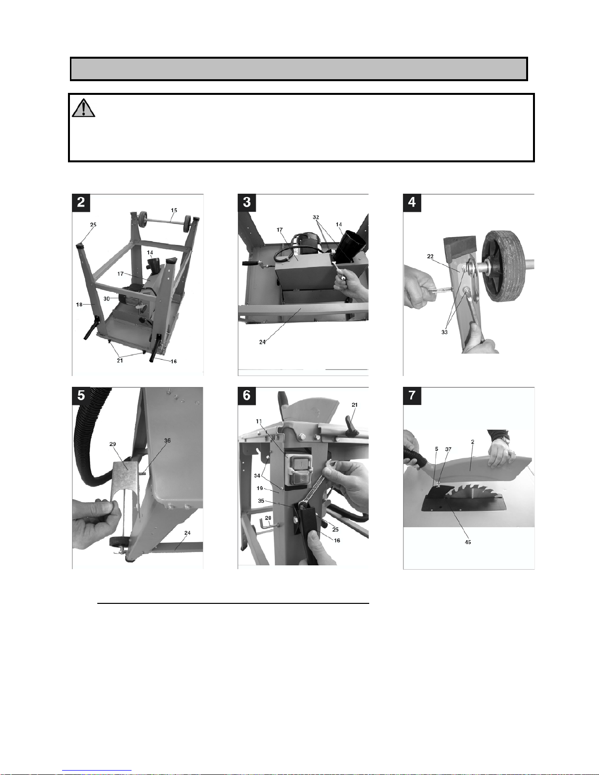
Fig. 1 - 6
A) MONTAGGIO DEL BASAMENTO DEL BANCO SEGA
• Posizionate il piano di lavoro (1) Fig. 1 su una superficie piana.
• Montate i piedi (18) sotto il piano di lavoro (1) senza stringere le viti Fig. 2.
Attenzione: sul piede (19) di Fig. 1 si deve fissare l’interruttore e quindi deve
essere montato correttamente (a sinistra del lato anteriore).
• Avvitate leggermente i rinforzi dei piedi (24) sui piedi della sega (18 e 19).
MONTAGGIO
Page 16
16
B) MONTAGGIO DEGLI ACCESSORI DEL BANCO SEGA
• Avvitate il manicotto d’aspirazione (14) sul lato inferiore della vaschetta di raccolta
segatura (17) con 4 viti (32) Fig. 3.
• Posizionat e i 4 piedini in gomma (25) sui piedi del banco sega Fig. 2.
• Montate le piastre di fissaggio (22) sul lato interno dei piedi posteriori (18) del banco
sega con 4 viti (33) Fig. 4.
• Capovolgete la sega e posizionatela sui suoi piedi.
• Inserite il gruppo dell’interruttore (11) nella fessura del piede (19) prevista a questo
scopo e avvitate saldamente usando due viti (34) Fig. 6.
• Montate le maniglie di spostamento (16) sui piedi anteriori con 2 viti (35) Fig. 6.
Attenzione: Le maniglie (16) sono dei pezzi mobili e devono abbassarsi
automaticamente!
• Avvitate il supporto del tubo di aspirazione (29) nella parte posteriore del piano di
lavoro (1) con 2 viti (36) Fig. 5.
• Regolate il basamento della macchina e avvitate correttamente tutte le viti utilizzate
precedentemente durante il montaggio
• Montate le due leve a scatto (21) Fig. 6 per fissare il binario della guida parallela
sulla parte frontale del piano di lavoro.
Attenzione: Avvitate le leve (21) ma non totalmente, altrimenti la guida parallela (7)
non può essere fissata.
• Montate il gancio porta-utensili (28) Fig. 6 sul lato di uno dei piedi della sega.
C) MONTAGGIO DELL’ESTENSIONE DEL PIANO DI LAVORO
• Montate l’estensione della tavola (10) nella parte posteriore del piano di lavoro (1)
con 2 viti, senza stringerle.
• Posizionate poi i supporti di appoggio (26) Fig. 1 dell’estensione del piano e fissateli
solidamente utilizzando i fori previsti a questo scopo.
• Abbiate cura di allineare l’estensione della tavola (10) con il piano di lavoro (1), poi
avvitate totalmente tutte le viti.
D) UTILIZZO DELLE RUOTE PER LO SPOSTAMENTO
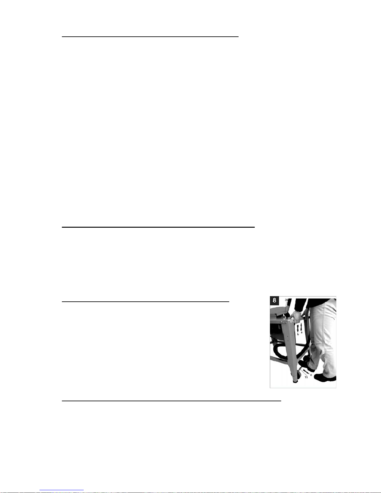
• Per utilizzare il telaio di trasporto, sollevate la sega dal retro
(a) Fig. 8 e spingete le ruote (15) indietro (b).
• Riabbassate il banco sega (c) Fig. 8.
• Sollevando il banco con le maniglie (16) Fig. 6 potete
spostare o trasportare facilmente la sega.
Attenzione: Dopo aver spostato la sega, il t elaio di trasporto
con le ruote (15) deve essere subito neutralizzato in modo da
garantire una posizione stabile al banco sega: per far ciò
procedete nell’ordine inverso.
E) MONTAGGIO / SMONTAGGIO DELLA PROTEZIONE DELLA LAMA
• Posizionate la protezione (2) Fig. 7 sul coltello divisore (5) e fate passare la vite (37)
attraverso il foro (45) del coltello divisore.
• Non avvitate la vite (37) totalmente; la protezione lama deve potersi alzare e
abbassare liberamente.
• Fissate una delle estremità del tubo di aspirazione (13) Fig. 1 sull’adattatore (14) Fig.
3 e l’altra estremità sull’attacco per il tubo della protezione della lama (2).
Page 17
17
• Collegate successivamente un sistema di aspirazione adeguato all’uscita
dell’adattatore di aspirazione.
Attenzione: la protezione della lama (2) deve essere abbassata sull’oggetto da tagliare
prima di cominciare l’operazione di taglio.
ATTENZIONE!
Prima di effettuare qualsiasi regolazione, manutenzione, intervento sulla sega,
assicuratevi che sia spenta e scollegata da qualsiasi fonte di corrente.
Per garantirvi una sicurezza ed un utilizzo preciso ed efficace della sega, dovete
osservare le procedure di regolazione seguenti.
Quando tutte le regolazioni sono state effettuate, assicuratevi che tutte le chiavi e gli
utensili siano lontani dalla macchina, e che tutte le viti, i bulloni e altri dispositivi di
fissaggio siano correttamente bloccati.
Non utilizzate la sega prima di aver seguito queste procedure.
Mentre effettuate queste regolazioni, controllate che tutti i pezzi esterni funzionino
correttamente e siano in buono stato.
I pezzi rotti o danneggiati devono essere riparati o sostituiti da una persona
qualificata prima dell’utilizzo della sega.
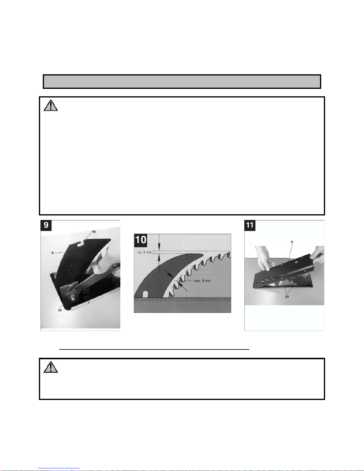
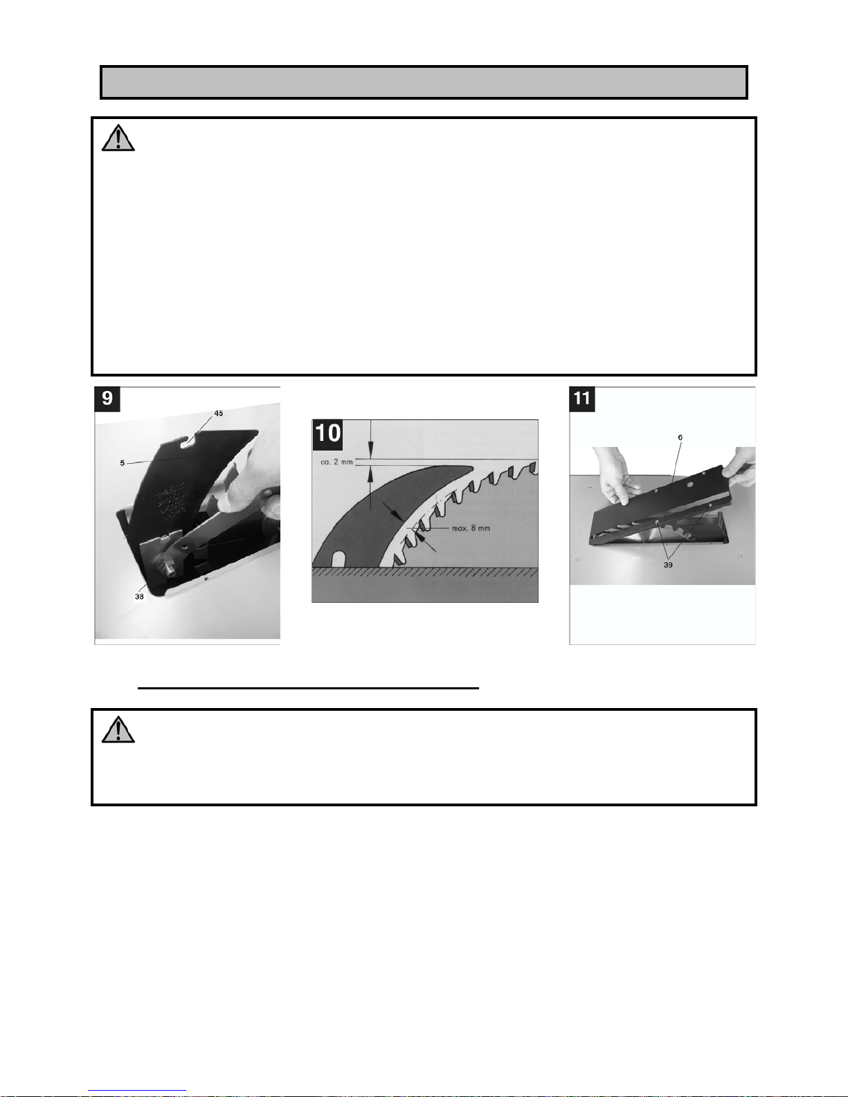
B) REGOLAZIONE DEL COLTELLO DIVISORE (Fig. 7, 9, 10, 11)
ATTENZIONE!
Assicuratevi che la sega sia spenta e scollegata da ogni sorgente di corrente prima di
procedere al montaggio o di effettuare qualsiasi tipo di regolazione.
• Posizionat e la lama (4) Fig. 1 a 0° e alla massima profondità di taglio.
• Smontate la protezione della lama (2) Fig. 1.
• Togliete l’inserto del piano di lavoro (6) Fig. 1 poi allentate la vite di fissaggio del
coltello (38) Fig. 9.
REGOLAZIONI
Page 18
18
• Tirate il coltello d ivisore (5) Fig. 9 al massimo verso l’alto in modo che la distanza tra
la superficie del piano di lavoro (1) Fig.1 e la parte superiore del coltello divisorio (5)
sia la più grande possibile.
• Posizionat e il coltello in modo che la distanza tra la lama della sega (4) e il coltello
divisore (5) sia al massimo di 8 mm.
• Riavvitate in modo energico il dado (38) Fig. 9 e rimontate l’inserto del piano di
lavoro (6).
• Rimontate la protezione mobile della lama.
C) SOSTITUZIONE DELL’INSERTO DEL PIANO DI LAVORO (Fig. 11)
• Quando l’inserto del piano di lavoro (6) è usurato o danneggiato deve essere
sostituito per evitare potenziali rischi.
• Levate la protezione della lama della sega (2) Fig. 7.
• Svitate le viti (39) Fig. 11.
• Togliete l’inserto del piano di lavoro (6) usurato dall’alto.
• Procedete in ordine inverso per rimontare l’inserto del piano di lavoro sul piano, fino
al rimontaggio della protezione.
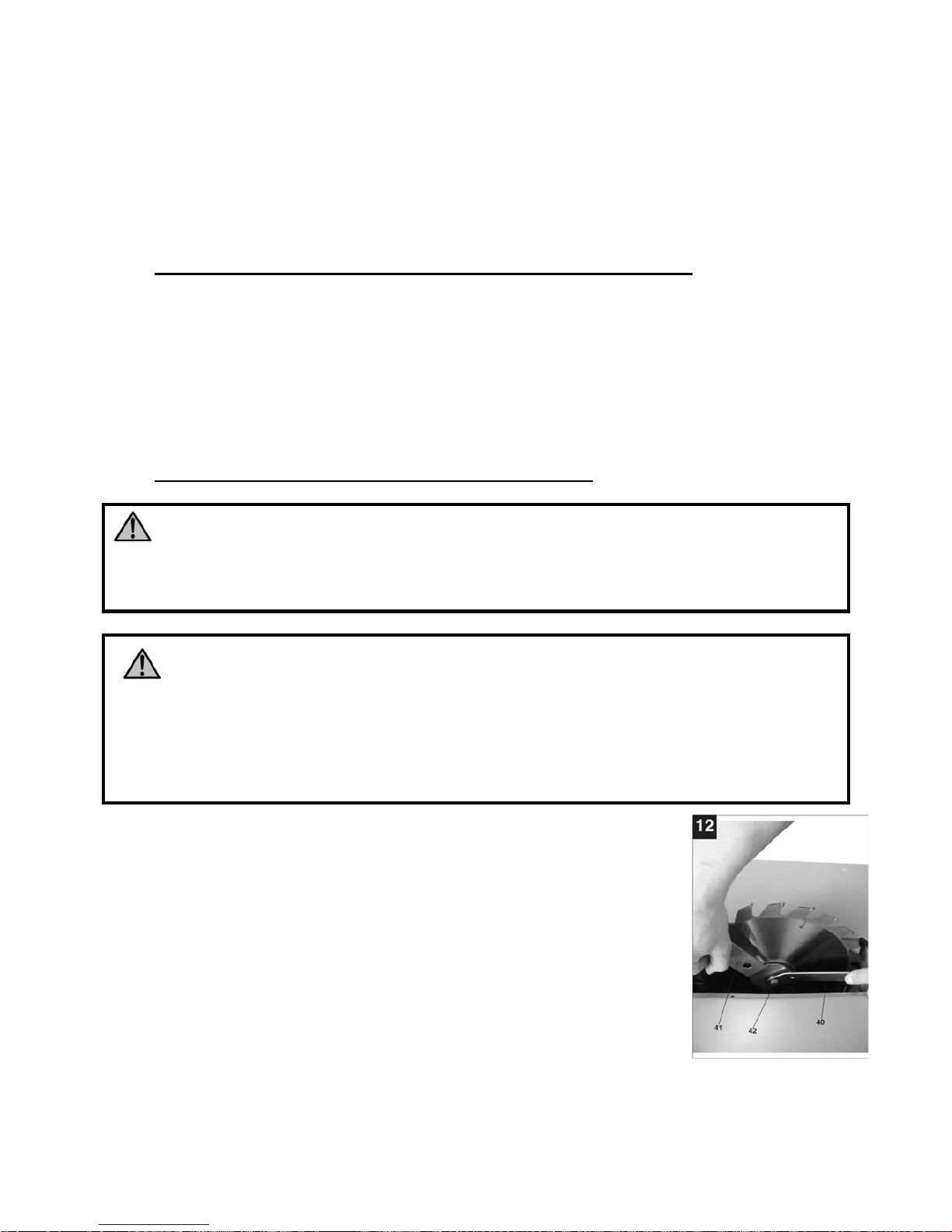
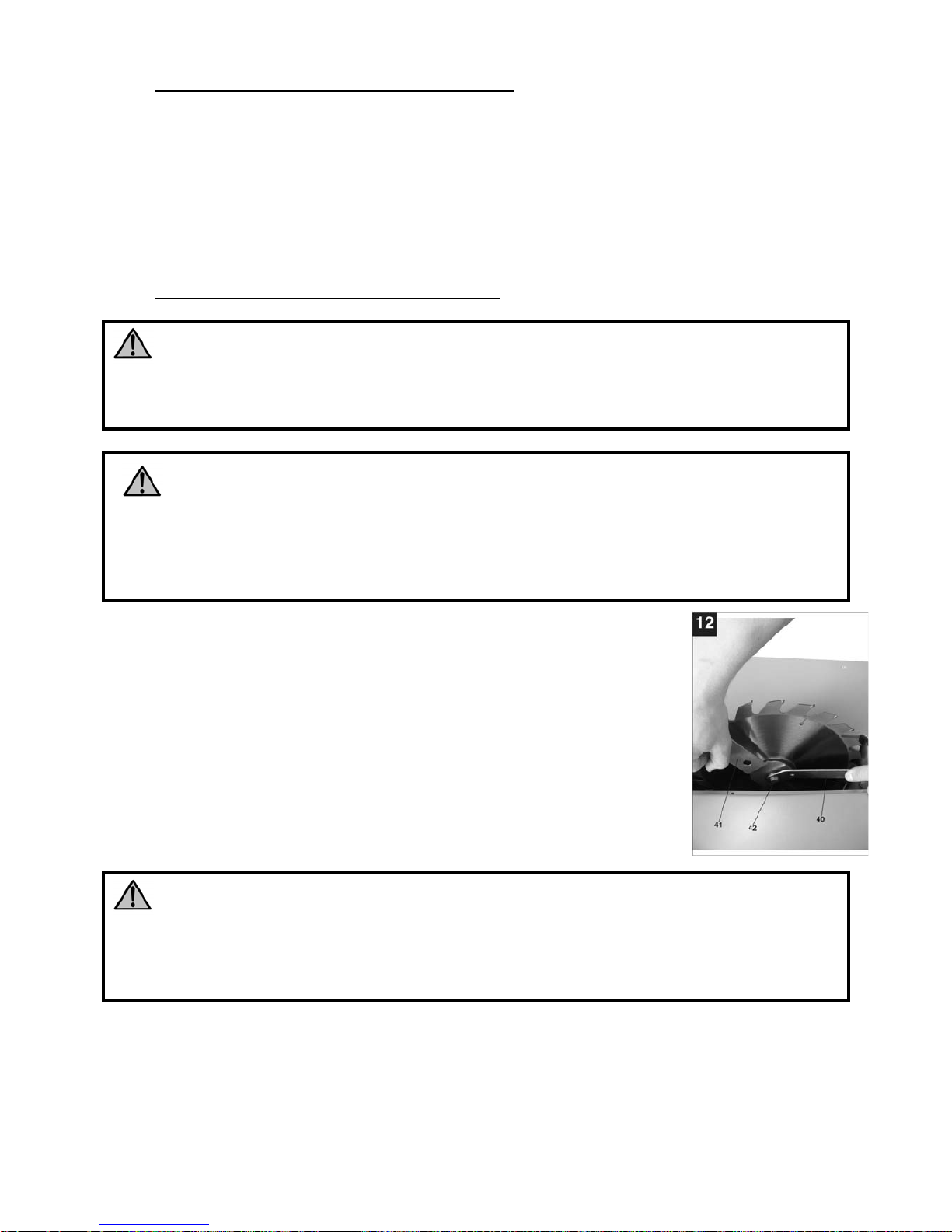
D) SOSTITUZIONE DELLA LAMA DELLA SEGA (Fig. 12)
ATTENZIONE!
Assicuratevi che la sega sia spenta e scollegata da ogni sorgente di corrente prima di
procedere al montaggio o di effettuare qualsiasi tipo di regolazione.
ATTENZIONE!
Verificate che le caratteristiche della lama che volete montare siano coerenti con
i dati riportati nella “Caratteristiche Tecniche“. Non utilizzate mai una lama di diametro
più grande rispetto alla dimensione di origine, in quanto potrebbe entrare in contatto
con la protezione. Non rispettare le dimensioni originali può comportare un grande
pericolo.
• Alzate al massimo la lama della sega (4).
• Levate la protezione della lama (2) (vedere par. “MONTAGGIO
E SMONTAGGIO DELLA PROTEZIONE DELLA LAMA”).
• Togliete l’inserto del piano di lavoro (6).
• Posizionate la chiave di bloccaggio dell’albero (41) a livello della
lama della sega Fig. 12 e svitate la vite (42) attraverso la chiave
(40) (nel senso di rotazione della lama della sega).
• Prima del montaggio della nuova lama della sega, le flangie
della lama devono essere pulite accuratamente.
• Posizionate la nuova lama della sega, la flangia e stringete in
modo energico la vite di fissaggio della lama.
Page 19
19
ATTENZIONE!
Rispettate il senso di rotazione della lama. I denti della lama devono sempre puntare
verso il basso e nel senso del movimento, cioè verso la parte frontale (vedere la
freccia sulla protezione della lama e sulla lama).
• Posizionate il coltello divisore e controllate che sia perfettamente allineato con la
lama.
• Montate l’inserto del piano di lavoro e la protezione mobile della lama, verificando
che funzioni correttamente
• Fate girare la lama a mano per verificare che non ci siano interferenze.
• Collegate la sega e avviatela un istante senza utilizzarla, per verificare che n on ci sia
alcun problema.
AVVERTENZA: Utilizzate solamente delle lame previste per il taglio trasversale. Quando
utilizzate delle lame con placchette in metallo duro, assicuratevi che abbiano un angolo di
taglio nullo o negativo. Non utilizzate delle lame con denti profondi in quanto possono
piegarsi ed entrare in contatto con la protezione della lama. Se possibile preferite lame
silenziate per attenuare il rumore.
PREMESSA
• Prima di utilizzare il banco sega, controllate che tutte le protezioni e i dispositivi di
sicurezza siano montati e funzionanti.
• La macchina deve essere stabile e saldamente fissata al suolo.
• La lama della segatrice deve poter ruotare liberamente.
• Se volete tagliare dei pezzi di legno già lavorati, fate attenzione che non ci siano dei
corpi estranei come per esempio chiodi o viti.
• Prima di avviare la segatrice, assicuratevi che la lama sia montata correttamente.
• Prima di collegare la macchina, accertatevi che la tensione di alimentazione corrisponda
a quella marcata sulla targhetta dati della macchina
A. INTERRUTTORE AVVIO / ARRESTO (Fig. 6)
Per avviare il banco sega, premete il pulsante verde ”I”
dell’interruttore.
Per spegnere la sega, premete il pulsante rosso ”O” dell’interruttore.
L’interruttore utilizzato su questa sega è del tipo a “minima
tensione“ ed impedisce il riavviamento automatico della sega in
caso di ripristino dell’energia elettrica dopo un’interruzione; quindi
quando si verificano interruzioni di energia elettrica la sega si ferma
e per farla ripartire si deve premere nuovamente il pulsante verde.
B. PROTEZIONE DEL MOTORE
La sega è dotata di un disgiuntore termico per la protezione del
motore. Prima che la temperatura del motore raggiunga valori
FUNZIONAMENTO
Page 20
20
pericolosi per l’integrità dell’avvolgimento, interviene il protettore termico che interrompe
l’alimentazione al motore. Per fare ripartire la sega si deve ripremere il pulsante verde, dopo
aver atteso il raffreddamento del motore.
C. FRENATURA DELLA LAMA
Questo utensile è dotato di un freno meccanico che ferma la lama in meno di 10 secondi dal
momento in cui si preme il tasto arresto. Controllare periodicamente l’efficienza della
frenatura; se non funzionante portarla ad un centro assistenza.
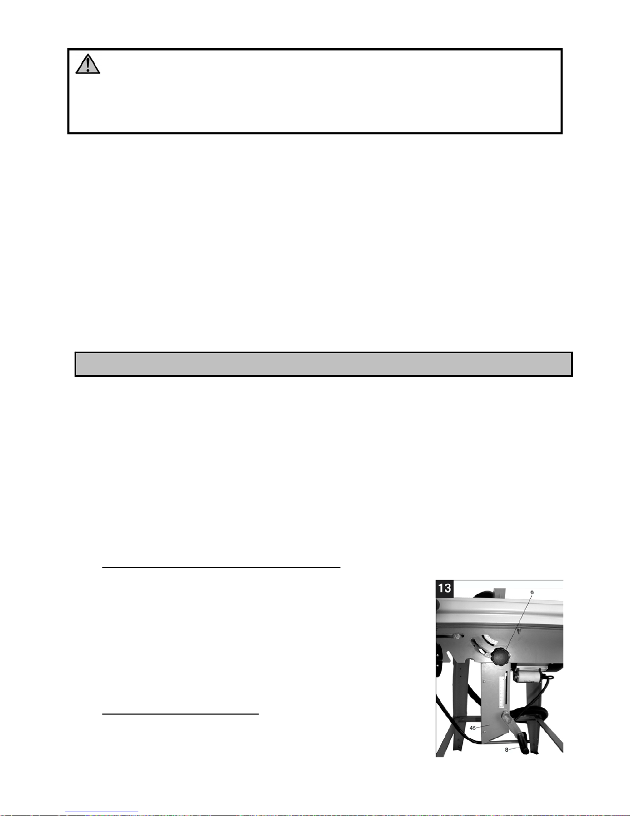
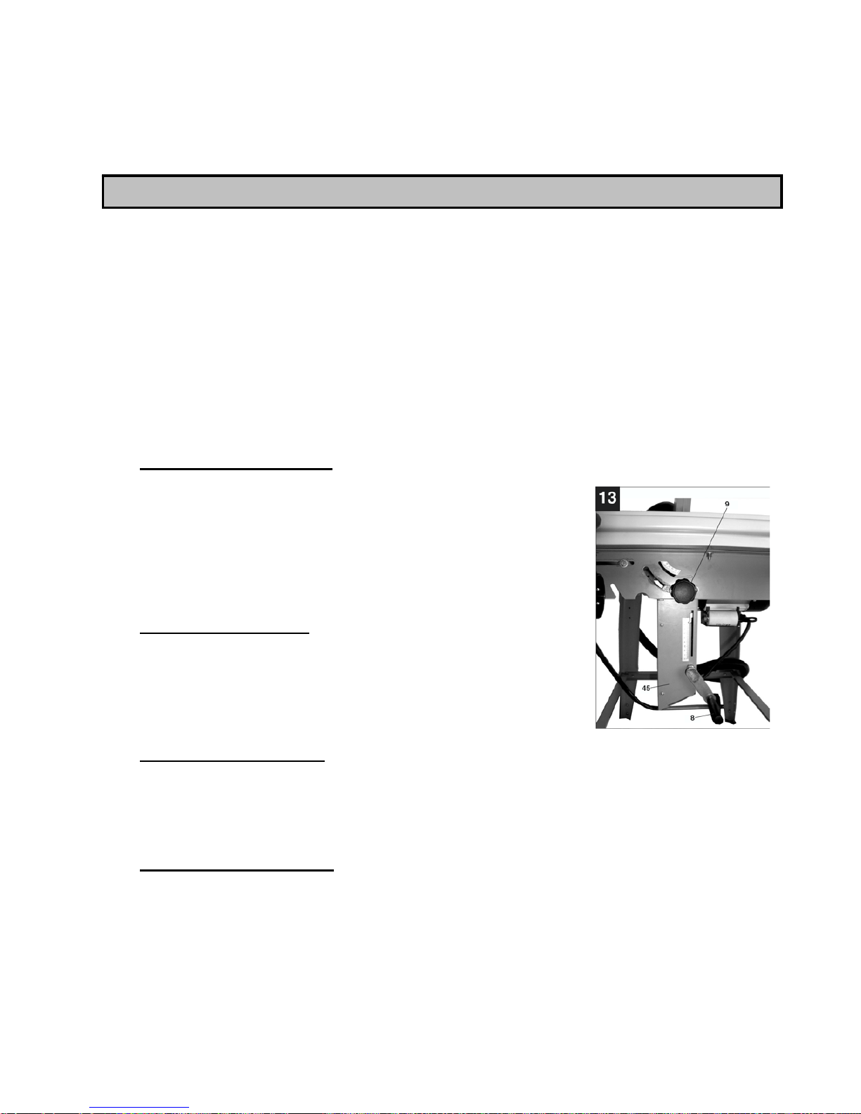
D. PROFONDITÀ DI TAGLIO (Fig. 13)
Per regolare la profondità di taglio ruotate la manovella (8) Fig. 13, che fa salire o scendere
la lama rispetto al piano di lavoro.
Ruotate la manovella in senso antiorario per aumentare la profondità di taglio, in senso orario
per diminuire la profondità di taglio. Una scala graduata di indicazione dell’altezza di taglio
permette di visualizzare con precisione la profondità di taglio desiderata Fig. 13.
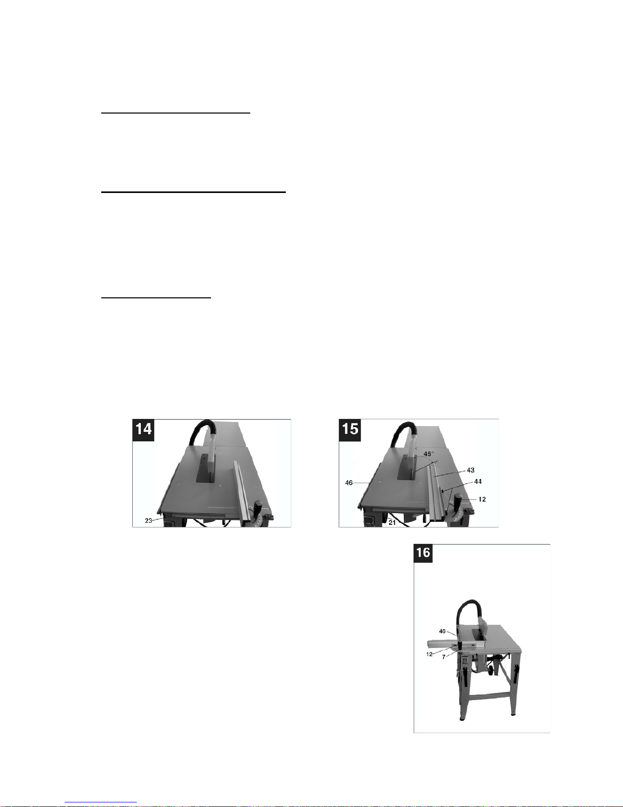
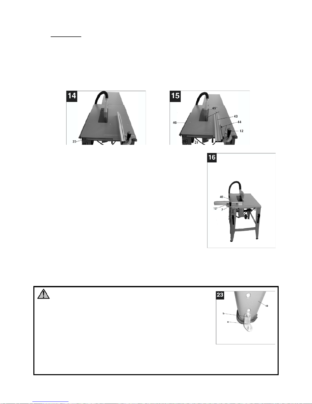
E. GUIDA PARALLELA
• La guida parallela (7) Fig. 1 è dotata di due altezze di guida diverse e serve per i tagli
longitudinale e quelli trasversali.
• In funzione dello spessore dei materiali da tagliare, la guida parallela (23) può essere
posizionata su uno dei suoi due lati di appoggio:
- per un pezzo di legno spesso, posizionate la guida come illustrato nella Fig. 14.
- per un pezzo di legno sottile, posizionate la guida sull’altro lato (vedere Fig.
15).
• La guida parallela (7), per tagli longitudinali, deve essere
montata sul lato destro della lama della sega (4) e deve
scorrere sul binario (23) situato sulla parte frontale del
piano di lavoro. Posizionate la guida parallela nella
posizione desiderata e bloccatela con le leve a scatto
(21).
• Per tagli trasversali inserite la guida parallela (7) nel
binario di guida (46) Fig. 16, nel quale deve scorrere
liberamente
• Allentate l’impugnatura del goniometro (12).
• Fate ruotare il goniometro (7) fino a che l’indicatore non
segnali l’angolo desiderato
• Successivamente stringete l’impugnatura del goniometro
(12) per bloccarlo in posizione.
• Attenzione: Non spingete la guida troppo vicina alla
lama della sega. La distanza tra la guida e la lama (4) deve essere di circa 2 cm.
Page 21
21
• Per tagli con lama inclinata: allentate il volantino di inclinazione della lama (9) Fig.
13.
• Spingete la protezione della lama e vaschetta di raccolta della segatura posta sotto il
piano (45) verso sinistra fino a che non ottenete l’angolo desiderato.
• Stringete completamente il volantino di regolazione dell’inclinazione (9).
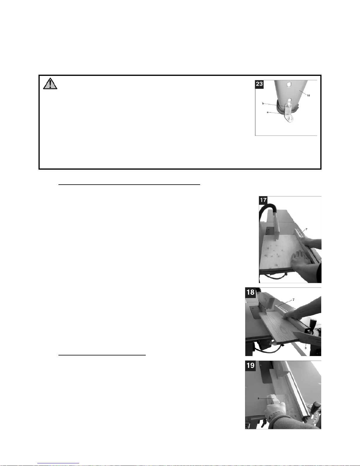
ATTENZIONE!
- Prima dell’avvio, la segatrice deve essere fissata al suolo tramite
le barrette a squadra metalliche fornite. Per fare ciò, fissate
il basamento come illustrato nella Fig. 23 tramite le barrette
in metallo (a) con le viti (b) nei piedi (18) e 4 tasselli per il cemento.
- Dopo ogni regolazione, fate delle prove di taglio per controllare
la sistemazione.
- Dopo l’avvio della sega, aspettate che la lama della segatrice
abbia raggiunto la sua velocità di rotazione massima prima di iniziare il taglio.
- Fate attenzione all’inizio del taglio!
F. REALIZZAZIONE DEI TAGLI LONGITUDINALI
Con i tagli longitudinali il legno si taglia nel senso della lunghezza. Un
bordo del pezzo da lavorare è appoggiato alla guida parallela (7) Fig.
17 mentre il lato piatto è posizionato sul piano di lavoro (1).
La protezione della lama della segatrice (2) deve essere sempre
abbassata sul pezzo da lavorare.
• Regolate la guida parallela (7) in funzione dell’altezza del pezzo
da tagliare e della larghezza desiderata.
• Avviate la segatrice.
• Posizionate le mani, a dita congiunte, sul pezzo da lavorare e
spingete il pezzo lungo la guida parallela (7) contro la lama
della segatrice (4).
• La spinta di avanzamento e laterale contro la guida è realizzata
con la mano sinistra fino a quando la parte frontale della
protezione (2) non è tornata in contatto con il piano di
lavoro.
• Spingete sempre il pezzo da lavorare fino alla parte
posteriore del coltello divisore (5).
• Il pezzo di legno di scarto che resta sul piano di lavoro (1)
si tolga a sega spenta e a lama ferma.
G. TAGLIO DEI PEZZI PICCOLI
• I tagli longitudinali dei pezzi di larghezza inferiore a 120
mm, per ridurre i rischi di contatto con la lama, devono
essere assolutamente effettuati con lo spingipezzo che è
fornito con la macchina. Sostituite immediatamente lo
spingipezzo usurato o danneggiato se necessario (Fig.
18).
• Per i tagli longitudinali di pezzi molto sottili (cioè di
larghezza di 30 mm o meno), utilizzate assolutamente uno
spingipezzo di legno (a) Fif. 19.
Page 22
22
• Osservate la Fig. 19 per vedere l’utilizz o di tale spingipezzo per il legno durante la
lavorazione di un pezzo di legno molto sottile.
• Questo tipo di spingipezzo, non fornito con la macchina, è facilmente reperibile ne i
negozi specializzati e deve essere sostituito se usurato o danneggiato.
• Durante il t aglio di un pezzo molto sottile, utilizzate la guida parallela come illustrato
nella Fig. 15.
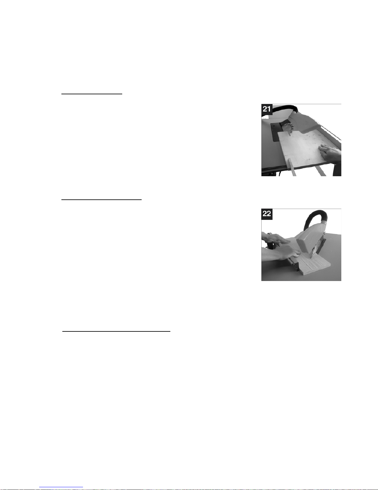
H. TAGLIO OBLIQUO
Il taglio obliquo si effettua normalmente in appoggio alla guida
parallela :
• Regolate la lama della sega (4) secondo l’angolo desiderato
(Fig. 21).
• Regolate la guida parallela (7) in funzione della larghezza e
dell’altezza del pezzo da lavorare.
• Effettuate il taglio secondo la larghezza del pezzo da
tagliare (vedere la procedura per tagliare i pezzi di legno
sottili e molto sottili).
I. TAGLIO TRASVERSALE
• Posizionat e la guida con goniometro sul binario a sinistra
del piano di lavoro e selezionate l’angolo desiderato.
• Il pezzo da tagliare deve essere appoggiato al goniom etro
(7) Fig. 22 e tenuto ben fermo.
• Avviate la macchina.
• Spingete il goniometro (7) e il pezzo da lavorare in direzione
della lama della segatrice per effettuare il taglio.
• Attenzione: Tagliate solo pezzi ben appoggiati e ben stretti.
Mai tentare di tagliare pezzi non adeguatamente bloccati.
• Continuate a spingere il goniometro (7) fino a che il pezzo da lavorare non sia
completamente tagliato.
• Arrestate nuovamente la sega. Eliminate la segatura del legno solamente quando la
lama si è completamente fermata.
J. ASPIRAZIONE DELLA POLVERE
La polvere di molti legni si è rivelata dannosa per la salute dell’uomo e, pertanto, si
raccomanda di collegare il banco sega ad un sistema di estrazione della polvere, singolo o
centralizzato, per l’eliminazione della segatura prodotta durante il lavoro; si raccomanda
anche di procedere ad una pulizia sistematica della macchina per l’eliminazione di tutta la
polvere che non viene aspirata nel corso del lavoro.
Collegare quindi il tubo di aspirazione al manicotto N.14 di Fig.2 di diametro 100 mm, posto
nella parte inferiore della macchina; in questo attacco arriva anche il tubo di aspirazione
collegato alla protezione superiore della lama, che deve sempre essere collegato per
garantire un’efficace estrazione della polvere.
L’impianto esterno dovrà avere una portata di aspirazione superiore a 800 m3/h, per
garantire una velocità di aspirazione di almeno 23 m/sec con polvere secca e di 28 m/sec
con polvere che abbia una percentuale di umidità superiore al 18%.
Page 23
23
MANUTENZIONE
ATTENZIONE!
Assicuratevi che la segatrice sia spenta e scollegata da ogni sorgente di corrente
prima di procedere al montaggio o di effettuare qualsiasi tipo di regolazione.
Qualsiasi danneggiamento delle protezioni, o anomalia riscontrata nel funzionamento o nel
corso del controllo della sega deve essere riparato immediatamente da personale qualificato
per quel tipo di intervento.
Prima di ogni utilizzo verificate che le protezioni e le sicurezze siano perfettamente efficienti e
al termine del lavoro spegnete e scollegate la sega e mettete in ordine il posto di lavoro.
Nel caso di un uso intensivo del banco sega, le periodicità delle verifiche potrebbe essere :
1. Quotidianamente
Aspirare la segatura che potrebbe accumularsi all’interno della macchina e pulire le apertura
di ventilazione del motore e il piano di lavoro.
Mantenere la protezione della lama sempre perfettamente scorrevole.
2. Settimanalmente
Mantenere scorrevole la salita-discesa e l’inclinazione da 0 a 45° del gruppo lama.
3. Mensilmente
Misurare il tempo di fermata della lama; se superiore a 10 secondi farla riparare da un centro
assistenza.
Verificare la rumorosità del motore.
Verificare l’integrità del cavo di alimentazione.
ANOMALIE DI FUNZIONAMENTO
La sega non parte:
- Mancanza di corrente nella presa in cui è inserito il cavo di alimentazione
- Cavo di alimentazione difettoso
- Motore in avaria
Vibrazioni sulla macchina:
- Pomello di fissaggio dell’inclinazione non bloccato
- Lama fissata male
Il legno si annerisce durante il taglio:
- Utensile non adeguatamente affilato
- Utensile montato al contrario
Usura rapida degli utensili:
- Utensile non adeguatamente affilato
- Legno sporco (cemento, sabbia, )
Funzionamento anomalo del motore:
- Possibile avaria del motore; fare controllare da un elettricista
La lama in lavoro si ferma:
- Sovraccarico (avanzamento troppo forte, utensile non affilato)
Il legno è respinto dalla lama:
- Mancanza di parallelismo della guida
- Cattivo allineamento del coltello divisore
Eventualmente:
- Rumore a livello dei cuscinetti: far sostituire i cuscinetti a sfera
Page 24

24
ASSISTENZA
Tutti gli utensili e accessori Fox sono costruiti e controllati utilizzando le più moderne e sicure
tecniche produttive. Se nonostante queste attenzioni un utensile dovesse guastarsi la
riparazione deve essere fatta da un centro riparazioni autorizzato Delta France.
L’elenco dei centri assistenza è reperibile presso i vari punti vendita o telefonando a
051/6946469 o inviando una richiesta all’ indirizzo di posta elettronica
[email protected]
Page 25

25
Table saw 315 mm (F36-528 model)
Index:
• Safety instructions 26
• General safety instructions 27
• Specific safety instructions for circular saws 29
• Environment protection 31
• Symbols 31
• Electrical connections 32
• Recommended use 33
• Technical specifications 34
• Noise conditions 34
• Removal of package 34
• Machine description 36
• Assembly instructions 37
A. Assembly of the base 37
B. Assembly of the accessories 38
C. Assembly of the workbench extension 38
D. Use of transport wheels 38
E. Assembly / removal of the protective cap 38
• Adjustments 39
A. Adjustment of the riving knife 39
B. Replacement of the bench inlay 40
C. Replacement of the saw blade 40
• Use 41
Introduction 41
A. On/Off switch 41
B. Engine protection 41
C. Saw braking system 41
D. Cutting depth 41
E. Rip fence 42
F. Longitudinal cutting 43
G. Cutting of small pieces 43
H. Mitre cut 43
I. Cross cutting 44
J. Dust collection 44
• Maintenance 44
• Malfunctions 45
• After sales service 46
Page 26

26
CAUTION:
Besides following the instructions mentioned in this manual, when using electric equipment
you must always observe all safety precautions to prevent risk of fire, electric shock and
personal injury.
Read this instruction manual before use and keep it carefully.
Working with an electric machine can be dangerous if you do not follow suitable safety
measures. As for any electric machine with moving parts, the use of a tool entails some risks.
If you use the machine as prescribed in this manual, you pay careful attention to the work you
are doing, you observe the regulations and you use the suitable personal devices of
protection, you can reduce the probability of risk. The possible remaining risks are related to:
1 – direct or in direct contacts with electrical shock
2 – injuries due to contact with moving parts
3 – injuries due to contact with angular parts
4 – injuries due to the ejection of tool parts or of the material you are processing
5 – injuries due to noise
The probability of risk can be reduced by the machine safety equipment of the machines, as
for example the protections, the blade case, the clamping, the stoppage and the personal
protection devices as protective goggles, the dust mask, ear plugs, protective shoes and
gloves. However, even the best protection devices cannot protect you from the risks due to
lack of good sense and attention. Have always good sense and observe the necessary
precautions. Carry out only the works that you consider safe. DO NOT FORGET: everyone is
responsible for his safety.
This tool has been designed for specific purposes. We recommend you not to modify it or use
it for purposes different from the ones for which it has been manufactured. If you have any
doubts regarding specific applications, do not use the machine before having contacted us
and received our instructions.
READ AND KEEP THIS MANUAL
SAFETY INSTRUCTIONS
Page 27

27
1. Keep the work surface clean. If the work area or surface is busy the probability of
injuries is higher.
2. Do not use the machine in dangerous environment conditions. In order to prevent
electric shock, do not expose the machine to rain and do not use it in a damp area.
Keep the work area illuminated. Do not use the machine near gas or inflammable
substances.
3. Connect the dust collection device. If the machine is provided with a dust collection
device, make sure that this system is connected and correctly used.
4. Keep unknown persons and childr en away from the machine. All unknown persons and
children must keep a safe distance from the work area.
5. Protect yourself from electric shock. Avoid any contact with earthing surfaces.
6. Handle the power supply cable with care. Do not pull the electric cable to disconnect it
from the plug. Keep the electric cable away from heat, oil and sharp edges.
7. Use extension cables designed for outdoor use. When using the machine outdoors, use
only extension cables suitable for outdoor use, having specific indications.
8. Be vigilant. Check carefully what you are doing, have good sense. Do not use the
machine if you are tired.
9. Do not use the machine if you are have taken medicines, alcohol, drugs.
10. Avoid accidental starts. Be sure that the switch is on the OFF position before inserting
the plug into the socket.
11. Wear appropriate clothing. Do not wear loose-sleeved garments or pieces of jewellery
which may get caught in the moving parts. For outdoor use we recommend non-slip
shoes. Use headgear to cover hair if necessary.
12. Use always personal protection devices: wear protective goggles and masks in case
dust or sawdust is produced. Wear ear muffs or plugs in noisy areas. Wear gloves when
handling parts with sharp edges.
13. Do not be off balance over the machine. Always keep stand firmly.
14. Ask for advices to expert and qualified people if you are not familiar with using such a
machine.
15. Remove the tools you do not use from the workbench. If you do not use the tools, you
must arrange them in a dry area which is locked and away from the reach of children.
16. Do not force the machine. You can obtain better and safer results if you use the
machine at the cutting pressure for which it has been designed.
GENERAL SAFETY INSTRUCTIONS
Page 28

28
17. Use the suitable tool. Do not use a small tool for an intensive job. Fox example, do not
use a circular saw to cut branches or stumps.
18. Block the piece. If possible, use C-clamps or a holder to fix the piece. It is safer than
using only your hands.
19. Keep the tools in perfect conditions. Keep the tools sharp and clean to obtain better and
safer results. Follow the instructions to grease and change the accessories. Check
regularly the electric cable and change it if it is damaged. Keep the handles and the
handgrips dry, clean, unoiled and ungreased.
20. Disconnect the tool from electricity if you do not use it, before maintenance and change
of the accessories or tools such as blades, drills, mills, etc.
21. Remove locking and adjustment wrenches from the workbench. Get used to check if
the locking and adjustment wrenches have been removed before starting it.
22. Check the parts of the tool to verify that there are not any damages. Before using the
machine, check if the safety devices or any other parts are damaged in order to be sure
that it works properly and that it can accomplish the tasks for which it has been
designed. Check that the moving parts are aligned, do not stop and are not broken.
Check the assembly and any other condition that can influence the functioning of the
machine. Any part or protection damaged must be repaired or changed from an
authorised after sales centre. Do not use the machine if the switch does not work
properly.
23. Use the machine, the tools and accessories in the way and for the purposes mentioned
i this manual. Different uses and parts can cause possible risks for the operator.
24. Get the machine repaired by a qualified person. This electric tool is in compliance with
local safety regulations. The machine must be repaired only by qualified people who
use original spareparts, otherwise risks may arise for the operator.
Page 29

29
1. DO NOT start the saw until it is assembled and inst alled according to the instructions of
this manual.
2. ALWAY S USE the protective cap, the riving knife and the clamping device in order to
cut the piece completely. This means cutting the piece in all its depth.
3. ALWAYS PRESS the workpiece firmly against the oblique guide or on the rip fence.
4. USE always a clamping device in order to push the piece of wood through the blade
and in particular to cut small pieces. To get further information on the clamping device,
check the sections regarding longitudinal cutting in this manual.
5. NEVER work freehand. Always use the oblique guide or the rip fence to position and
direct the piece you are cutting.
6. ALWAY S KEEP A SAFE DISTANCE from the blade axe. KEEP the hands away from
the blade’s track.
7. DO NEV ER keep your hands behind or over the blade and ensure that you and your
hands are in a comfortable position.
8. REMOVE the rip fence during cross cutting.
9. DO NOT USE the rip fence for cross cutting.
10. PUSH ALWAYS the piece you have to cut through the saw blade or the tool.
11. DO NOT TRY to remove the saw blade before switching off the tool. Also if you want to
stop cutting, put the switch on the OFF position and wait for the blade to stop rotating.
You can perform tasks of any kind only if the blade is still and the machine is
disconnected from the power supply.
12. DO NOT remove wood piles caught between the blade and the inlet if the blade is
rotating. You can intervene after switching off the machine and having waited for the
blade to stop rotating.
13. LEAN on a support the ends of big workpieces which come out sideways or behind the
workbench.
14. AVOID workpieces hittig back in your direction by taking the following measures:
A. Always use a sharp and suitable saw blade;
B. Check the parallelism between the guide and the blade;
C. Always use the riving knife, the clamping device and the protective cap;
D. Never release the workpiece before it has been completely pushed through the
saw;
E. Do not saw bent or deformed workpieces which do not have a straight side that
allows a regular advancement along the guide.
SPECIFIC SAFETY RULES FOR CIRCULAR SAWS
Page 30

30
15. NEVER USE thinners to clean the plastic pieces of the machine. Thinners can melt or
damage the material. Only use a damp cloth for cleaning plastic workpieces.
16. INSTALL the saw PERMANENTLY on a plane surface before using it.
17. DO NEVER CUT any metals or materials that can produce dangerous dust.
18. ALWAYS USE the table saw in a well ventilated area. Often remove the sawdust.
Remove carefully the sawdust that is inside the saw to avoid the risk of fire.
19. DO NOT use saw blades which are damaged or deformed or high speed blades in high
alloy ( as for example HSS ).
20. USE only saw blades recommended by the manufacturer, in complianc e with EN 847-1
standard.
21. USE only correct saw blades, which are suitable to the material to be cut and on which
the marked speed is higher than the one of the machine. When changing the blade,
check if external diameter and bore diameter are correct, that cutting width and the
blade body are not thinner than the riving knife width. Transport the saw blade inside its
case.
22. CHANGE the plastic table inlay which is located on the table around the blade when
worn or damaged.
23. USE this table saw only to cut wood and similar materials.
24. CHECK often if the supply cable is damaged, and in this case get it repaired by an
authorised after sales centre. Check often the extension cord and change it if it is
damaged.
25. CONNECT the machine to a dust-collecting device and USE ear protective devices and
the dust mask.
Page 31
31
INFORMATION FOR USERS
In accordance with art. 13 of Legislative Decree 25th July 2005, no. 151 “Implementation of
Directives 2002/95/EEC, 2002/96/EEC and 2003/108/EEC, relative to reducing the use of
hazardous substances in electric and electronic appliances and the disposal of waste”,
please take note of the following:
• The crossed out wheelie bin symbol found on the appliance or the packaging indicates
that the product must be disposed separately from ordinary household waste when it
reaches the end of its working life.
• The user must consign the unwanted appliance to an authorized waste dispos al centre
for electric and electronic goods, or alternatively, hand it over to the relative dealer at
the moment of purchasing a new appliance of the same type on a basis of a one to
one ratio.
• Differentiated disposal to enable possible recycling or environmentally compatible
elimination of the appliance, helps to limit undesirable effects on health and
environment and promotes the reuse and/or recycling of the materials that compose
the appliance.
WARNING!
In accordance with the relative legislation in force in the country of use, sanctions will
be imposed on the user if the appliance is disposed of illegally.
Always wear protective goggles.
Read carefully the instruction manual before use.
Always wear the dust mask.
Always wear ear protectors.
ENVIRONEMENT PROTECTION
SYMBOLS
Page 32
32
Heavy package. For the transport of the machine two persons are necessary.
Machine in conformity with relative CE standards.
Double insulation. Tools which have this symbol have not any earthing protection
systems.
It is forbidden to put your hands in this area. Danger of
dragging/cutting.
Indicates that this machine is equipped with a laser
Serial number / year of production
ELECTRICAL CONNECTIONS
Use 230 V 50 Hz alternate voltage equipped with a earthing conductor to supply your
machine. Ensure that the power supply corresponds to this voltage, that it is protected by a
differential and magnetothermal switch, and that the earthing system is efficient. If your
machine does not work when connected to a socket, check carefully the power supply
features.
Use an extension cable in order to connect the machine to the power supply.
EARTHING INSTRUCTIONS
If the tool does not work properly or in case of short-circuit, the earthing system provides the
current with a less resistance path and reduces the risk of electric shock. This tool has a plug
to which a supply or extension cable must be connected, which in turn must be connected to
a socket correctly installed and earthed, in conformity with local standards and regulations.
Be sure that your earthing system is in good conditions and that your plug is protected by a
differential and magnetothermal switch.
If the earthing conductor is not connected correctly the risk of electric shock can occur. The
conductor which has the green insulating jacket (with or without a yellow line) is the earthing
conductor.
ELECTRICAL CONNECTIONS
Page 33
33
Consult a qualified electrician or a person in charge of the maintenance if you have not
understood or you have some doubts on the earthing instructions.
If the supply cable is damaged it must be changed by qualified people. Do not switch on the
machine if the supply cable is damaged.
EXTENSION LEADS
Only use three conductors extension leads, with a plug with two plugs and a earthing contact
and sockets with two holes and a earth corresponding to the plug of the tool. When using an
electric tool at a remarkable distance from the power supply, use an extension lead with
sufficient dimensions to transport the current which the tool needs. If the extension lead has
not the sufficient dimensions a voltage drop can occur, thus causing an overheating and a
voltage loss. You can only use extension leads which are in compliance with CE standards.
Extension lead length: up to 15 m
Cable dimensions: 3 x 2,5 mm²
Before using any kind of extension lead, check that it has not bare wires and that the
insulation is not cut or worn. Repair and change immediately it if it is damaged or worn.
WARNING:
Extension leads must be arranged away from the working area in order that they not get in
touch with the workpieces, the tool or other parts of the machine, thus creating possible risks.
WARNING:
KEEP THE TOOLS AND THE EQUIPMENT AT A SAFE DISTANCE FROM CHILDREN
This machine has been manufactured only for wood cropping and cutting up to a width of 83
mm when the saw blade is in a straight position, and up to 60 mm when the saw blade is in a
45 ° inclined position.
The machine is stable enough, but if necessary, it is possible to fix it to the ground.
USE LIMITS
DO NOT cut wood wider than 83 mm
DO NOT cut metal, stone, rubber, plastics, chalk, glass wool, etc.
DO NOT cut stubs or irregular wood pieces.
NO NOT assemble other tools or different saw blades.
DO NOT use it as a portable tool or a not fixed machine.
DO NOT modify the machine, the safety and protection devices or the switches.
RECOMMENDED USE
Page 34
34
Engine power: 1800 W
Voltage and frequency: 230 V - 50 Hz
Service: S2 20%
Speed: 2860 min¯¹
Saw diameter: 315 mm
Bore diameter: 30 mm
Blade width when assembled: 1,8 mm
Cutting width when the blade is assembled: 2,8 mm
Workbench dimensions: 800 x 550 mm
Extension dimensions: 800 x 400 mm
Cutting height 90°: 83 mm
Max cutting height 45°: 60 mm
Blade inclination: 0 - 45 °
Packaging dimensions: 825 mm x 590 mm x 435 mm
Weight: 52 kg
The noise emitted, measured in conformity with the standards EN 3744 and EN 11201 is:
- Sound pressure level LpA = 83,2 dB(A) without load and 94 dB(A) with load
- Sound power level LWA = 96,1 dB(A) without load and 108,7 dB(A) with load
- Uncertainty of measurement K = 3 dB
We recommend you to use ear protection devices.
The sources of the noise of the saw are: the electric engine and its ventilation system, the
blade and the material to be cut.
We advise you to control the engine, its ventilation system and the aspiration passages. As
far as the saw blade is concerned, it is preferable to use silenced type of blades and to keep
them in good conditions. We recommend to use the correct saw blade and to keep firmly the
workpiece to be cut.
Noise levels are emission levels and do not necessarily indicate safe working conditions.
Even if there is a connection between emission levels and exposure levels, the first ones
cannot be used to determine safely if other precautions are necessary. The factors that can
influence the actual exposure level of the operator include the exposure length, environment
features and other sources of noise, as for example the number of machines and operations
present. Besides, exposure levels can change from country to country. However, these
instructions enable the user of the machine to better evaluate the dangers and risks.
Your table saw is delivered complete in a package.
Remove the table saw and all the parts from the packaging, check if there are any missing or
damaged parts.
If you find any faulty or damaged parts do not use them in order not to endanger the
efficiency and the safety of the machine. To change faulty parts consult an after sales centre.
TECHNICAL SPECIFICATIONS
NOISE CONDITIONS
REMOVAL OF PACKAGE
Page 35
35
To make the table saw work perfectly you must assemble the various parts, for which you
can find a detailed explanation later on.
We recommend you to read carefully the assembly instructions and to follow them to the
letter. Remove any protections with a cleansing, as for example WD40. Do not use petrol or
varnish thinner.
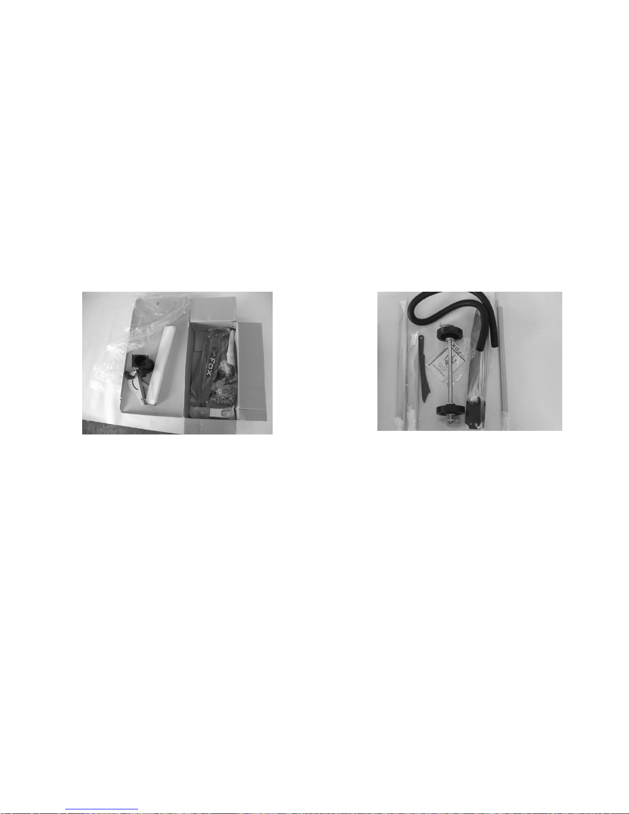
The following photos illustrate the parts included in the packaging besides the main body of
the machine.
1 – N°2 Extensions supports 9 – N°1 Rip fence
2 – N°1 Hind foot 10 – N°1 Goniometer
3 – N°1 Aspiration pipe 11 – N°1 Aspiration outlet
4 – N°1 Wheels group 12 – N°1 Upper protection
5 – N°4 Feet + N°4 rubber feet 13 – Screws and washers
6 – N°2 Short bars 14 – N°2 Wrenches for saw blade assembly
7 – N°2 Long bars 15 – N°1 Aspiration pipe case
8 – N°1 Pusher 16 – N°2 Handles
Page 36
36
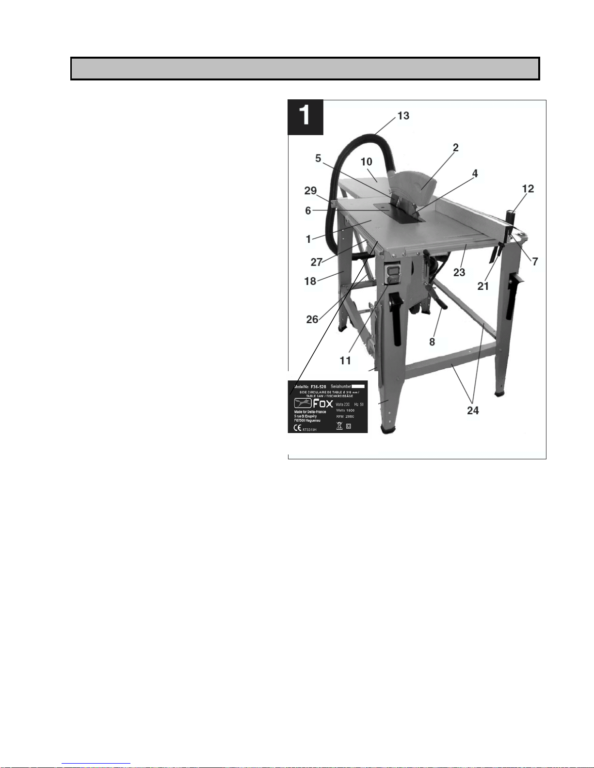
1. Workbench
2. Protection cap
3. Pusher
4. Saw blade
5. Riving knife
6. Bench inlay
7. Rip fence and goniometer
8. Height handle
9. Mitre handle ( Fig. 13)
10. Workbench’s back extension
11. ON/OFF switch
12. Hand grip for blocking the
goniometer
13. Flexible aspiration pipe
14. Aspiration coupling Ø 100 mm (Fig.
2)
15. Transport wheel holder (Fig. 2)
16. Transport handle (Fig. 2)
17. Chip pan (Fig. 2)
18. Machine’s base
19. Leg
21. Rip fence’s locking lever
22. Anchor plate for blocking the wheels
during transport (Fig. 4)
23. Rip fence’s slide rails
24. Feet backing strips
25. Rubber feet (Fig. 2 )
26. Workbench back extension bearings
27. Rip fence’s slide rail
28. Wrench and pusher hanger (Fig. 6)
29. Aspiration pipe holder (Fig. 5)
30. Engine (Fig. 2)
MACHINE DESCRIPTION
Page 37
37
WARNING!
Be sure that the saw is switched off and disconnected from any current source before
assembling it or carrying out any adjustment or maintenance task.
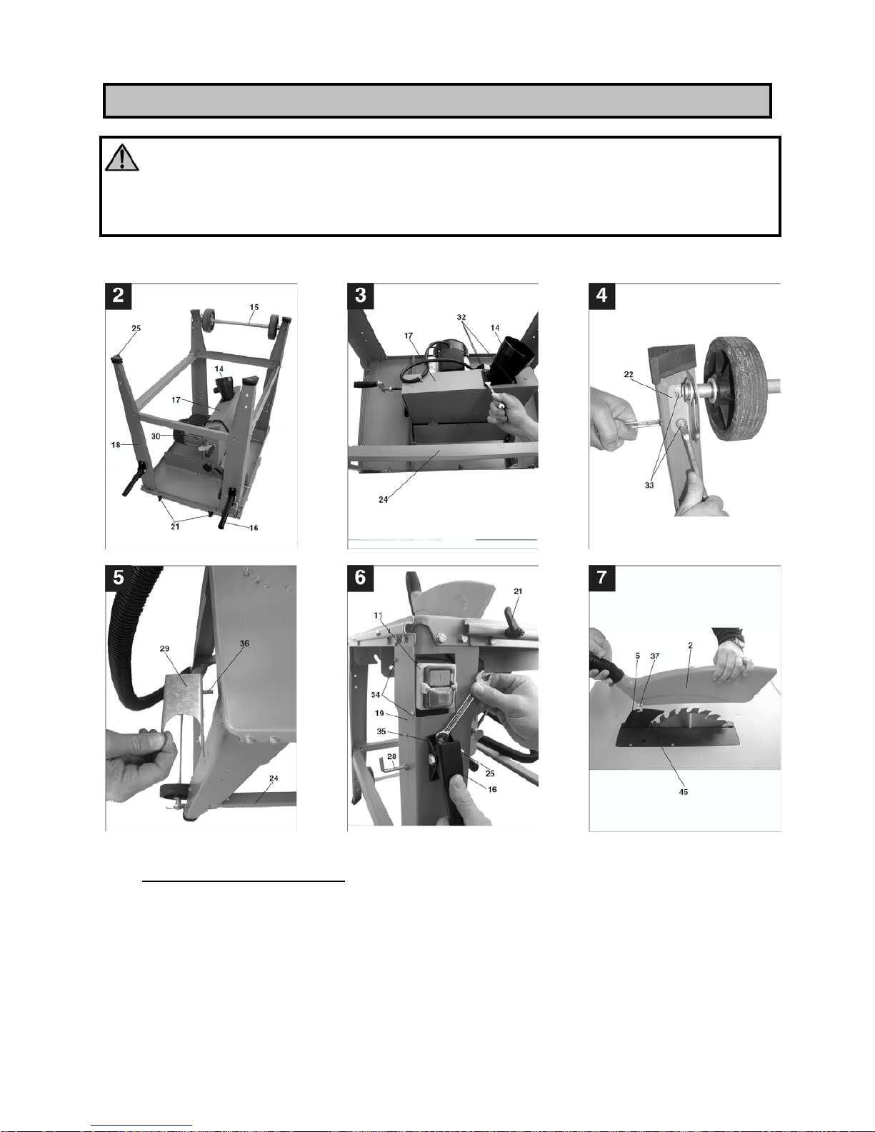
Fig. 1 - 6
A) ASSEMBLY OF THE BASE
• Put the workbench (1) Fig. 1 on a plane surface.
• Assemble the feet (18) under the workbench (1) without tightening the screws Fig. 2.
Warning: You must correctly fix the switch to the hind leg on the left (19) Fig. 1.
• Slightly tighten the leg backing strips (24) to the mitre saw’s legs (18 and 19).
ASSEMBLY INSTRUCTIONS
Page 38
38
B) ASSEMBLY OF THE ACCESSORIES
• Tighten the aspiration coupling (14) to the chip pan’s bottom side (17) by means of 4
screws (32) Fig. 3.
• Place the 4 rubber feet (25) on the mitre saw’s legs Fig. 2.
• Assemble the anchor plates (22) on the inner side of the hind leg (18) of the table
saw with 4 screws (33) Fig. 4.
• Turn the mitre saw upside down and position it on its legs.
• Insert the switch group (11) in the foot inlay (19) designed for this purpose and
tighten firmly with 2 screws (34) Fig. 6.
• Assemble the transport handle (16) on the front legs with 2 screws (35) Fig. 6.
Warning: The handles (16) are moving parts and must lower automatically!
• Tighten the aspiration pipe holder (29) in the workbench’s back side (1) with 2 screws
(36) Fig. 5.
• Adjust the machine’s base and tighten correctly all the screws that you have used
before during assembly.
• Assemble the two locking levers (21) Fig. 6 to block the rip fence’s slide rail on the
front side of the workbench.
Warning: Screw the levers (21) but not wholly, otherwise the rip fence (7) cannot be
fixed.
• Assemble the tool hanger (28) Fig. 6 on the side of one of the legs of the saw.
C) ASSEMBLY OF THE WORKBENCH EXTENSION
• Assemble the workbench extension (10) in the workbench’s backside (1) with 2
screws, but do not tighten them.
• Place the workbench’s extension bearings (26) Fig. 1 and fix them firmly using the
holes designed for this purpose.
• Align the workbench extension (10) with the workbench (1), then tighten firmly all the
screws.
D) USE OF TRANSPORT WHEELS
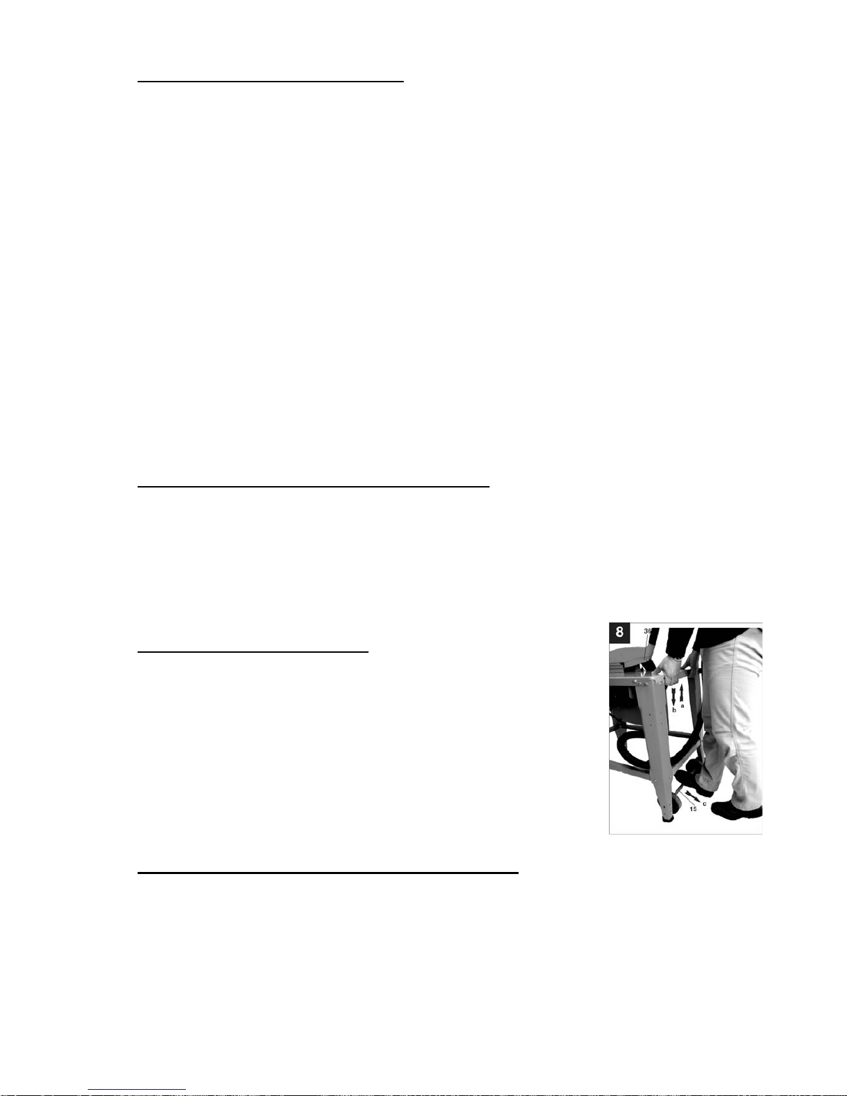
• Lift the machine from the backside (a) Fig. 8 and push
backwords (b) the wheels (15) to transport it.
• Lower the table saw (c) Fig. 8.
• Easily move or transport the mitre saw by using the handles
(16) Fig. 6.
Warning: After having moved the saw, the transport structure
with wheels (15) must be replaced in its initial position in order
to ensure a stable position of the table saw: to do this follow
these instructions in reverse order.
E) ASSEMBLY / REMOVAL OF THE PROTECTIVE CAP
• Position the protective cap (2) Fig. 7 on the riving knife (5) and let the screw (37)
pass through the riving knife’s hole (45).
• Do not tighten the screw (37) wholly; the protective cap must rise and lower freely.
• Fix an end of the aspiration pipe (13) Fig. 1 to the coupling (14) Fig. 3 and the other
end to the protective cap’s pipe (2).
• Connect a suitable aspiration device to the end of the coupling.
Warning: the protective cap (2) must be lowered on the workpiece before starting
cutting.
Page 39
39
WARNING!
Before carrying out any adjustment or maintenance task, ensure that the machine is
switched off and that the plug is removed from the socket.
Observe the following instructions to obtain precise and effective results.
After carrying out all the adjustments, be sure that all the wrenches and the tools are
far from the machine, and that all screws, bolts and other locking devices are blocked
correctly.
Do not use the saw before following these procedures.
While carrying out these adjustements, check that all external pieces work correctly
and are in good conditions.
Before use, broken or damaged parts must be repaired or changed by a qualified
person.
A) RIVING KNIFE ADJUSTMENT (Fig. 7, 9, 10, 11)
WARNING!
Before carrying out any adjustment or maintenance task, ensure that the machine is
switched off and that the plug is removed from the socket.
• Place the blade (4) Fig. 1 at 0° and at its maximum cutting depth.
• Remove the protective cap (2) Fig. 1.
• Remove the bench inlay (6) Fig. 1, then loosen the riving knife’s locking sc rew (38)
Fig. 9.
• Pull the riving knife ( 5) Fig. 9 upwards until it reaches its maximum height in order
that the distance between the workbench surface (1) Fig.1 ad the upper side of the
riving knife (5) is the biggest possible.
• Place the knife in or der that the distance between the saw blade (4) and the riving
knife (5) is a maximum of 8 mm.
• Firmly tighten the nut (38) Fig. 9 and re-assemble the bench inlay (6).
• Re-assemble the moving protection cap.
ADJUSTMENTS
Page 40
40
B) REPLACEMENT OF BENCH INLAY (Fig. 11)
• When the bench inlay (6) is worn or damaged, it must be changed to avoid possibl e
risks.
• Pull the protective cap (2) Fig. 7.
• Unfasten the screw (39) Fig. 11.
• Remove the worn bench inlay (6) from the top.
• To re-assemble the bench inlay on the workbench follow these instructions in reverse
order up to the re-assembly of the protection cap.
C) REPLACEMENT OF SAW BLADE (Fig. 12)
WARNING!
Before carrying out any adjustment or maintenance task, ensure that the machine is
switched off and that the plug is removed from the socket.
WARNING!
Check that the features of the saw blade you want to assemble correspond to
the data of the “technical specifications” paragraph. Do not use a saw blade with a
diameter bigger than the one of the original blade, since it could get in touch with the
protective cap. It can be dangerous not to respect original dimensions.
• Lift the saw blade to the highest degree (4).
• Remove the protective cap (2) (see par. “ASSEMBLY /
REMOVAL OF THE PROTECTIVE CAP”).
• Remove the bench inlay (6).
• Place the locking wrench of the axle (41) on the saw blade Fig.
12 and unfasten the screw (42) with the wrench (40) (in the
rotation sense of the saw blade).
• Before assembling the new saw blade, you must clean the
flanges carefully.
• Place the new saw blade and the flange and tighten firmly the
saw blade’s locking screw.
WARNING!
Respect the rotation sense of the saw blade. Saw blade’s teeth must point downwards
and in the moving direction, that is to say towards the front side (see the arrow on the
protection cap and on the saw blade).
• Place the riving knife and check that it is aligned to the saw blade.
• Assemble the bench inlay and the moving protective cap, and check that it works
properly.
• Let the saw blade rotate by hand to check that there are not any obstacles.
• To check there are not any problems, connect the mitre saw and start it for a while
without using it.
Page 41
41
CAUTION: Use only saw blades designed for cross cutting. When using saw blades with
hard metal plates, be sure that they have a null or negative cutting angle. Do not use saw
blades with deeply cut teeth since they can bend and get in touch with the protective cap. If
possible, use silenced blades to minimize the noise.
INTRODUCTION
• Before using the saw blade, check that all protection and safety devices are assembled
and work properly.
• The machine must be stable and firmly fixed to the ground.
• The saw blade must rotate freely.
• If you want to cut workpieces that have already been processed, be careful that there
are not any extraneous parts as for example nails or screws.
• Before starting the table saw, be sure that the blade is assembled correctly.
• Before connecting the machine, ensure that the voltage corresponds to what it is
marked on machine’s data plate.
A. ON / OFF SWITCH (Fig. 6)
To start the table saw press the green button ”I” of the switch.
To switch off the saw, press the red button ”O” of the switch.
The switch of this machine is a “minimum voltage“ switch and
prevents the start of the machine in case of recovery of the electrical
energy after an interruption. So, you must press the green button to
re-start the saw that has stopped.
B. ENGINE PROTECTION
The saw has a thermal cut-out to protect the engine. This device
stops the engine’s power supply before the temperature reaches a
dangerous level for the winding. After the engine has cooled down,
press the green button to start again the saw.
C. SAW BRAKING SYSTEM
This tool has a mechanical brake that stops the blade in less than 10 seconds since when
you push the button. Check the efficiency of the brake periodically, and if it does not work
take the machine to an after sales service.
D. CUTTING DEPTH (Fig. 13)
Rotate the handle (8) Fig. 13 which lifts of lowers the blade to adjust cutting depth.
Rotate the handle clockwise to increase cutting depth and anti-clockwise to decrease cutting
depth. You can check cutting height precisely by means of the graduated scale Fig. 13.
USE
Page 42
42
E. RIP FENCE
• The rip fence has two guiding heights (7) Fig. 1 and you can use it for longitudinal
and cross cutting.
• According to the width of the materials you have to cut, the rip fence (23) can be
placed on one of its support sides:
- If the workpiece is thick, place the rip fence as illustrated in Fig. 14.
- If the workpiece is thin, place the rip fence on the other side (see Fig. 15).
• For longitudinal cutting the rip fence (7) must be
assembled on the right side of the saw blade (4) and
must slide on the rail (23) on the front side of the
workbench. Place the rip fence in the desired position
and lock it with the jumper lifts (21).
• For cross cutting place the rip fence (7) in the rail (46)
Fig. 16, in which it must slide freely.
• Loosen the goniometer hand grip (12).
• Let the goniometer (7) rotate until the gauge signals
the desired angle.
• Tighten the goniometer hand grip (12) to lock it.
• Warning: Do not place the rip fence too near to the
saw blade. The distance between the rip fence and
the saw blade must be of 2 cm approximately.
• For angle cutting loosen the inclination handle (9) Fig.
13.
• Push the protective cap and the chip pan located under the bench (45) to the left
until you reach the desired angle.
• Screw firmly the inclination handle (9).
WARNING!
- Before switching on the machine, the saw must be fixed to
the ground by means of the metal square bars included in the
packaging. To do so, fix the base to the ground as illustrated in
Fig. 23 by means of the metal bars (a) with the screws (b) in the
legs (18) and 4 anchor for cement.
- After any adjustment, do a cutting test to check the correctness
of it.
- After the starting of the machine and before starting cutting, wait for the blade to
reach its maximum rotational speed.
- Be careful to the cutting start!
Page 43
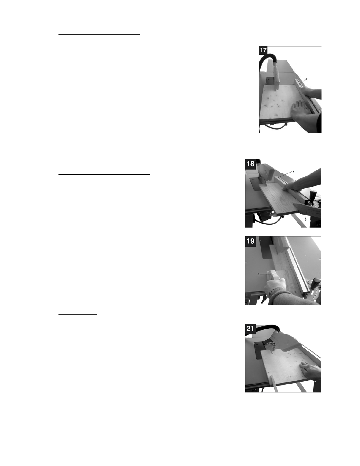
43
F. LONGITUDINAL CUTTING
A longitudinal cutting is a cutting carried out in the length sense of the
workpiece. A side of the workpiece is pressed to the rip fence (7) Fig.
17, while the plane side is placed on the workbench (1).
The protective cap (2) must be always lowered on the piece to be cut.
• Adjust the rip fence (7) according to the workpiece’s height and
to the desired width.
• Start the saw.
• Place the hands with joined fingers on the workpiece a nd push
it along the rip fence (7) through the saw blade (4).
• Push the workpiece forward and sideways with the left hand
until when the front side of the protective cap (2) gets in touch
with the workbench.
• Always push the workpiece beyond riving knife’s backside (5).
• Remove the waste wood which remains on the workbench (1) when the saw is
switched off and the blade is still.
G. CUTTING OF SMALL PIECES
• If you have to cut longitudinally any workpiece thinner t han
120 mm, you must absolutely use the pusher delivered
with the machine in order to avoid possible contacts with
the blade. Immediately change the worn or damaged
pusher if necessary (Fig. 18).
• If you have to cut longitudinally any workpiece thinner t han
30 mm, you must absolutely use a wooden pusher (a) Fig.
19.
• Observe Fig. 19 to see the use of the wooden pusher
during the processing of a very thin workpiece.
• This kind of pusher is not provided with the machine. You
can easily find it in specialised stores and must be
replaced if worn or damaged.
• During the cutting of a very thin piece, use the rip fence as
illustrated in Fig. 15.
H. ANGLE CUT
Normally angle cut is carried out with the workpiece pressed to the
rip fence:
• Adjust the saw blade (4) according to the desired angle
(Fig. 21).
• Adjust the rip fence (7) according to the width and the
height of the workpiece.
• Cut the workpiece according to the workpiece’s width (see
the paragraph about the cutting of small and very small
pieces).
Page 44
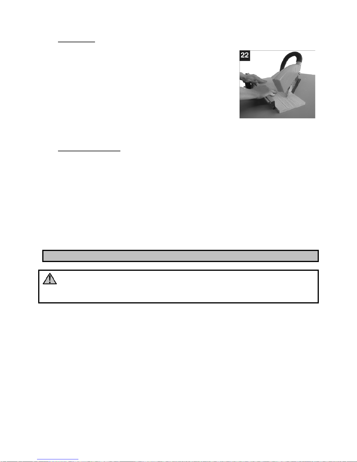
44
I. CROSSCUT
• Place the rip fence with goniom eter on the rail on the left
of the workbench and select the desired angle.
• The workpiece must be leant on the goniom eter (7) Fig.
22 and blocked firmly.
• Start the machine.
• Push the goniometer (7) and the workpiece against the
saw blade in order to cut.
• Warning: Cut only pieces properly leant and blocked. Do
never cut if the workpiece is not blocked properly.
• Keep on pushing the goniometer (7) until you cut it completely.
• Stop again the saw. Remove the chips only when the saw blad e is completely still.
J. DUST COLLECTION
The dust of various kinds of wood is dangerous for human health, so we recommend you to
connect the table saw to a single or centralized dust collection device to remove the dust
which has been produced during processing. We advise you also to make a general cleaning
of the machine to remove all the dust that has not been extracted during processing.
Connect the aspiration pipe to the Ø 100 coupling (14) Fig. 2 located in the lower part of the
machine. This coupling must always be connected also to the aspiration pipe of the upper
protective cap to extract the dust efficaciously.
The external device must have an aspiration capacity superior to 800 m3/h to ensure an
aspiration speed of at least 23/m>/sec with dry dust and of 28/m sec with dust having an
humidity percentage bigger than 18%.
MANTEINANCE
WARNING!
Before carrying out any adjustment or maintenance task, ensure that the machine is
switched off and that the plug is removed from the socket.
In case you find out any damage to the protection devices or irregularities while processing or
checking the machine, you must get it repaired immediately by qualified persons.
Before use check that the protection and safety devices are perfectly efficient. After carrying
out the work, make a general cleaning of the machine by removing dust and chips.
Extract periodically sawdust that can pile up inside the machine and clean the ventilation
inlets of the engine.
Be sure that the protective cap can slide freely.
Be sure that the saw blade group can smoothly lift, lower and angle from 0 to 45°.
Check the saw blade brake time, and if it is longer than 10 seconds take the machine to an
after sales service.
Check the noise of the engine periodically.
Periodically check that the supply cable is not damaged.
Remove the dirt from the workbench by means of a suitable maintenance spray.
Page 45

45
MALFUNCTIONS
The saw does not start:
- The electric current is missing in the socket to which the supply cable is connected.
- The supply cable is faulty
- The engine is damaged
Machine vibrations:
- The inclination handle is not blocked
- The blade is not fixed correctly
Wood darkens while cutting:
- The tool is not correctly sharpened
- The tool has been assembled back-to-front
The tools wear rapidly:
- The tool is not correctly sharpened
- The wood is dirty (cement, sand, etc.)
The engine does not work properly:
- The engine may be damaged: get the machine checked by an electrician
Blade stops rotating:
- Surcharge (the speed is too high, the tool is not sharpened)
The blade rejects the wood:
- The rip fence is not parallel
- The riving knife is not aligned correctly
Other:
- The bearings make noise: get them changed
Page 46

46
AFTER SALES SERVICE
All the tools and accessories are made and checked by using the safest and most modern
productive methods. However, if a tool get damaged, it must be repaired by an authorised
after sales centre.
You can call the phone number 051/6946469 or by sending a request to the e-mail address
[email protected]
Page 47
47
DICHIARAZIONE DI CONFORMITA’ CE DEL COSTRUTTORE
Femi SpA
Via Salieri 33/35 – 40024 - Castel S.Pietro Terme (BO) Italia
Tel. +39 051 6946469 - Fax +39 051 6946470
Dichiara che il: BANCO SEGA (F36/528)
è conforme alle disposizioni contenute nelle Direttive: (CEE 98/37) CEE 2006/42-2004/108-2006/95
CE DECLARATION OF CONFORMITY OF THE MANUFACTURER
Femi SpA
Via Salieri 33/35 – 40024 - Castel S.Pietro Terme (BO) Italia
Tel. +39 051 6946469 - Fax +39 051 6946470
Declares that the TABLE SAW (F36/528)
is in compliance with the regulations included in the Directives: (CEE 98/37) CEE 2006/42-2004/108-2006/95
15.11.2009
Il Presidente del Consiglio / The Director
Page 48
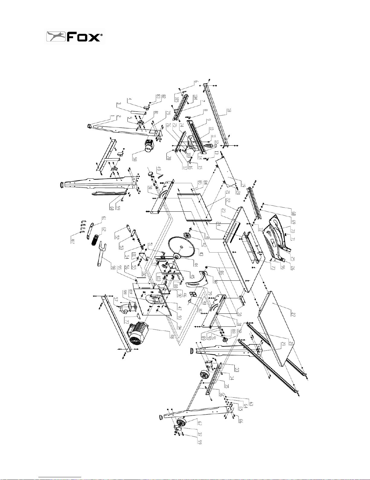
48
F36-528
BANCO SEGA 315 MM / TABLE SAW 315 MM
Page 49
49
F36-528
BANCO SEGA 315 MM / TABLE SAW 315 MM
N. Art. / Item N. Art. / Item
1 F36528-1 56 F36528-56
2 F36528-2 57 F36528-57
3 F36528-3 58 F36528-58
4 F36528-4 59 F36528-59
5 F36528-5 60 F36528-60
6 F36528-6 61 F36528-61
7 F36528-7 62 F36528-62
8 F36528-8 63 F36528-63
9 F36528-9 64 F36528-64
10 F36528-10 65 F36528-65
11 F36528-11 66 F36528-66
12 F36528-12 67 F36528-67
13 F36528-13 68 F36528-68
14 F36528-14 69 F36528-69
15 F36528-15 70 F36528-70
16 F36528-16 71 F36528-71
17 F36528-17 72 F36528-72
18 F36528-18 73 F36528-73
19 F36528-19 74 F36528-74
20 F36528-20 75 F36528-75
21 F36528-21 76 F36528-76
22 F36528-22 77 F36528-77
23 F36528-23 78 F36528-78
24 F36528-24 79 F36528-79
25 F36528-25 80 F36528-80
26 F36528-26 81 F36528-81
27 F36528-27 82 F36528-82
28 F36528-28 83 F36528-83
29 F36528-29 84 F36528-84
30 F36528-30 85 F36528-85
31 F36528-31 86 F36528-86
32 F36528-32 87 F36528-87
33 F36528-33 88 F36528-88
34 F36528-34 89 F36528-89
35 F36528-35 90 F36528-90
36 F36528-36 91 F36528-91
37 F36528-37 92 F36528-92
38 F36528-38 93 F36528-93
39 F36528-39 94 F36528-94
40 F36528-40 95 F36528-95
41 F36528-41 96 F36528-96
42 F36528-42 97 F36528-97
43 F36528-43 98 F36528-98
44 F36528-44 99 F36528-99
45 F36528-45 100 F36528-100
46 F36528-46 101 F36528-101
47 F36528-47 102 F36528-102
48 F36528-48 103 F36528-103
49 F36528-49 104 F36528-104
50 F36528-50 105 F36528-105
51 F36528-51 106 F36528-106
52 F36528-52 107 F36528-107
53 F36528-53 108 F36528-108
54 F36528-54 109 F36528-109
55 F36528-55
Page 50
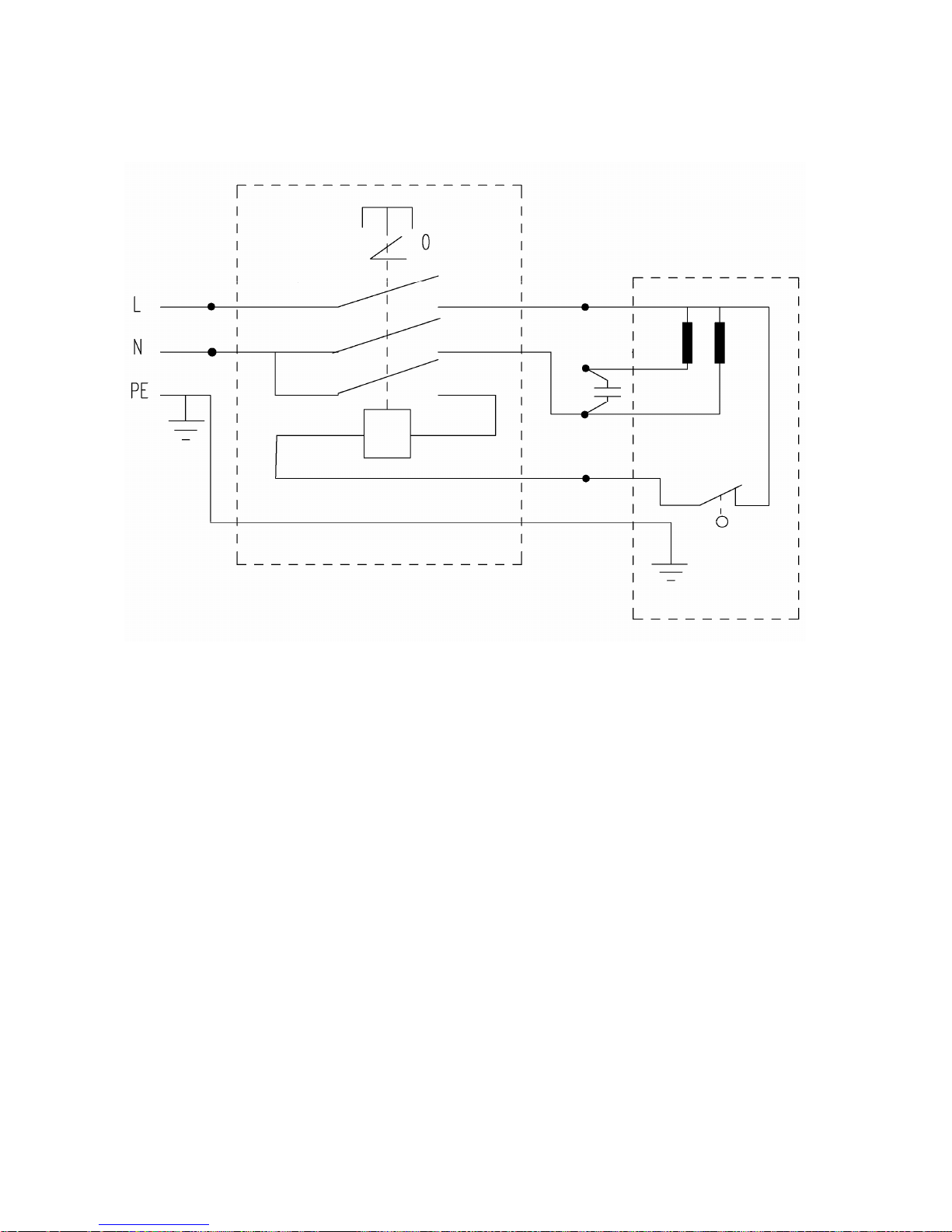
50
SCHEMA ELETTRICO / WIRING DIAGRAM
 Loading...