

Page 1
INSTRUCTION MANUAL
BANDSAW
(FOX model F28-186A)
Page 2
Page 3
Page 4
Page 5

5
BANDSAW
Index
Safety instructions 23
General safety instructions 24
Specific safety instructions for bandsaws 26
Environment protection 27
Symbols 27
Electrical connections 28
Recommended use 29
Technical specifications 29
Noise conditions 30
Removal of package 30
Machine description 31
Assembly of the bandsaw 32
I. Bandsaw fastening 32
II. Workbench assembly 32
III. Assembly of fence’s rail 32
IV. Assembly of the rip fence 33
V. Connection of the dust collection device 33
Protection of the blade 33
I. Upper protection of the saw blade 33
II. Lower protection of the saw blade 33
III. Flywheels’ doors 34
Functioning 34
I. ON / OFF switch 34
II. Saw blade’s tension 35
III. Knob for the adjustment of saw blade’s position 35
IV. Speed adjustment 35
V. Adjustment of workbench’s inclination 36
VI. Rip fence 36
VII. Cutting 36
Assembly of the blade and adjustments 37
I. Replacement of the saw blade 37
II. Adjustment of the saw blade 38
III. Adjustment of the upper blade guide 38
IV. Adjustment of the lower blade guide 38
Maintenance 39
I. General regulations 39
II. Replacement of the flywheels’ coatings 39
III. Replacement of the bench inlay 39
Malfunctions 40
After sales service 41
Page 6

6
CAUTION:
Besides following the instructions mentioned in this manual, when using electric equipment you
must always observe all safety precautions to prevent risk of fire, electric shock and personal
injury.
Read this instruction manual before use and keep it carefully.
Working with an electric machine can be dangerous if you do not follow suitable safety
measures. As for any electric machine with moving parts, the use of a tool entails some risks. If
you use the machine as prescribed in this manual, you pay careful attention to the work you are
doing, you observe the regulations and you use the suitable personal devices of protection, you
can reduce the probability of risk. The possible remaining risks are related to:
1 – direct or in direct contacts with electrical shock
2 – injuries due to contact with moving parts
3 – injuries due to contact with angular parts
4 – injuries due to the ejection of tool parts or of the material you are processing
5 – injuries due to noise
The probability of risk can be reduced by the machine safety equipment of the machines, as for
example the protections, the blade case, the clamping, the stoppage and the personal protection
devices as protective goggles, the dust mask, ear plugs, protective shoes and gloves. However,
even the best protection devices cannot protect you from the risks due to lack of good sense
and attention. Have always good sense and observe the necessary precautions. Carry out only
the works that you consider safe. DO NOT FORGET: everyone is responsible for his safety.
This tool has been designed for specific purposes. We recommend you not to modify it or use it
for purposes different from the ones for which it has been manufactured. If you have any doubts
regarding specific applications, do not use the machine before having contacted us and received
our instructions.
READ AND KEEP THIS MANUAL
SAFETY INSTRUCTIONS
Page 7

7
1. Keep the work surface clean. If the work area or surface is busy the probability of injuries
is higher.
2. Do not use the machine in dangerous environment conditions. In order to prevent electric
shock, do not expose the machine to rain and do not use it in a damp area. Keep the
work area illuminated. Do not use the machine near gas or inflammable substances.
3. Connect the dust collection device. If the machine is provided with a dust collection device,
make sure that this system is connected and correctly used.
4. Keep unknown persons and children away from the machine. All unknown persons and
children must keep a safe distance from the work area.
5. Protect yourself from electric shock. Avoid any contact with earthing surfaces.
6. Handle the power supply cable with care. Do not pull the electric cable to disconnect it
from the plug. Keep the electric cable away from heat, oil and sharp edges.
7. Use extension cables designed for outdoor use. When using the machine outdoors, use
only extension cables suitable for outdoor use, having specific indications.
8. Be vigilant. Check carefully what you are doing, have good sense. Do not use the machine
if you are tired.
9. Do not use the machine if you are have taken medicines, alcohol, drugs.
10. Avoid accidental starts. Be sure that the switch is on the OFF position before inserting the
plug into the socket.
11. Wear appropriate clothing. Do not wear loose-sleeved garments or pieces of jewellery
which may get caught in the moving parts. For outdoor use we recommend non-slip shoes.
Use headgear to cover hair if necessary.
12. Use always personal protection devices: wear protective goggles and masks in case
dust or sawdust is produced. Wear ear muffs or plugs in noisy areas. Wear gloves when
handling parts with sharp edges.
13. Do not be off balance over the machine. Always keep stand firmly.
14. Ask for advices to expert and qualified people if you are not familiar with using such a
machine.
15. Remove the tools you do not use from the workbench. If you do not use the tools, you must
arrange them in a dry area which is locked and away from the reach of children.
16. Do not force the machine. You can obtain better and safer results if you use the machine
at the cutting pressure for which it has been designed.
17. Use the suitable tool. Do not use a small tool for an intensive job. Fox example, do not use
a circular saw to cut branches or stumps.
18. Block the piece. If possible, use C-clamps or a holder to fix the piece. It is safer than using
only your hands.
19. Keep the tools in perfect conditions. Keep the tools sharp and clean to obtain better and
safer results. Follow the instructions to grease and change the accessories. Check regularly
the electric cable and change it if it is damaged. Keep the handles and the handgrips dry,
clean, unoiled and ungreased.
20. Disconnect the tool from electricity if you do not use it, before maintenance and change of
the accessories or tools such as blades, drills, mills, etc.
21. Remove locking and adjustment wrenches from the workbench. Get used to check if the
locking and adjustment wrenches have been removed before starting it.
22. Check the parts of the tool to verify that there are not any damages. Before using the
machine, check if the safety devices or any other parts are damaged in order to be sure
that it works properly and that it can accomplish the tasks for which it has been designed.
Check that the moving parts are aligned, do not stop and are not broken. Check the
assembly and any other condition that can influence the functioning of the machine. Any
part or protection damaged must be repaired or changed from an authorised after sales
centre. Do not use the machine if the switch does not work properly.
GENERAL SAFETY INSTRUCTIONS
Page 8

8
23. Use the machine, the tools and accessories in the way and for the purposes mentioned i
this manual. Different uses and parts can cause possible risks for the operator.
24. Get the machine repaired by a qualified person. This electric tool is in compliance with
local safety regulations. The machine must be repaired only by qualified people who use
original spareparts, otherwise risks may arise for the operator.
Page 9

9
1. ALWAYS DISCONNECT the bandsaw from the socket before any repair, maintenance or
cleaning task and while changing the blade.
2. DO NOT USE the bandsaw until it is not completely assembled or installed according to
this instruction manual.
3. START the bandsaw only after removing any object (tools, waste material, etc.) from the
workbench.
4. NEVER START the bandsaw when the blade is in contact with the workpiece.
5. START the bandsaw only after ensuring that the two doors are perfectly closed.
6. MOVE the upper guide the nearest to the workpiece.
7. CHECK that the blade guides and blade support bearings are correctly adjusted.
8. ENSURE that the blade is correctly tightened and that the teeth point downwards.
9. CHECK that the dimensions and the kind of blade are suitable to the work you must carry
out.
10. DO NOT TRY to cut a piece which has not any plane surface if you do not have a suitable
support.
11. PRESS the piece firmly to the bench and push it at a moderate speed.
12. STOP the machine if it rejects the workpiece before it is completely cut.
13. STOP the bandsaw to remove the stuck pieces or waste material on the workbench.
14. DO NOT CUT too small pieces that cannot be safely blocked.
15. CARRY OUT lightening cuts on the piece when you must do curved cuts.
16. NEVER CARRY OUT any preparation, assembly or adjustment tasks on the workbench
when the bandsaw is switched on.
17. KEEP always your hands and fingers far from the blade.
18. ALWAYS WEAR protective goggles.
19. AVOID uncomfortable positions in which your hands risk to slide or get in touch with the
blade.
20. DISCONNECT the machine, clean the workbench and lower the upper protective cap
before moving away from the machine. In case of long periods of inactivity loosen blade’s
tension.
21. CHANGE missing or damaged parts. Do not use the bandsaw if its parts do not perfectly
work.
22. REGULARLY CHECK if the supply cable is damaged, in that case get it repaired by an
authorised after-sales centre. Check regularly the extension cables and replace them if
they are damaged.
SPECIFIC SAFETY INSTRUCTIONS FOR BANDSAWS
Page 10
10
INFORMATION FOR USERS
“Implementation of Directives 2011/65/UE 2012/19/UE, relative to reducing the use of hazardous
substances in electric and electronic appliances and the disposal of waste”, please take note of
the following:
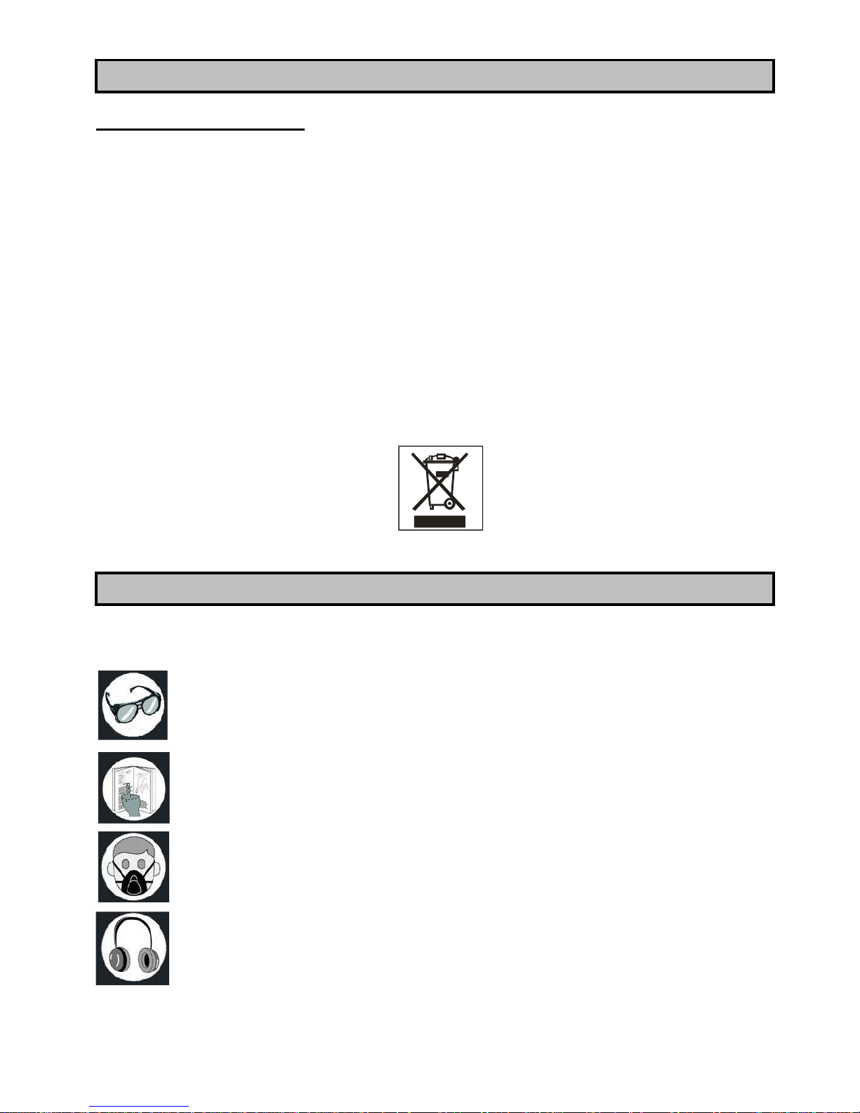
The crossed out wheelie bin symbol found on the appliance or the packaging indicates
that the product must be disposed separately from ordinary household waste when it
reaches the end of its working life.
The user must consign the unwanted appliance to an authorised waste disposal centre
for electric and electronic goods, or alternatively, hand it over to the relative dealer at the
moment of purchasing a new appliance of the same type on a basis of a one to one ratio.
Differentiated disposal to enable possible recycling or environmentally compatible
elimination of the appliance, helps to limit undesirable effects on health and environment
and promotes the reuse and/or recycling of the materials that compose the appliance.
WARNING!
In accordance with the relative legislation in force in the country of use, sanctions will be
imposed on the user if the appliance is disposed of illegally.
The following symbols can appear on your machine or in this instruction manual. Their meanings
are specified below:
Always wear protective goggles to avoid any spurts during the use of the machine.
Read and understand the instruction manual before use.
Always wear a dust mask if the operation produces dust.
Always wear ear protective devices which protect you from noise while using the
machine.
ENVIRONMENT PROTECTION
SYMBOLS
Page 11
11
Product in compliance with relative CE regulations.
Serial number / year of production
ELECTRICAL CONNECTION
ELECTRICAL CONNECTIONS
Use 230 V 50 Hz alternate voltage equipped with a earthing conductor to supply your machine.
Ensure that the power supply corresponds to this voltage, that it is protected by a differential
and magnetothermal switch, and that the earthing system is efficient. If your machine does not
work when connected to a socket, check carefully the power supply features.
Use an extension cable in order to connect the machine to the power supply.
EARTHING INSTRUCTIONS
If the tool does not work properly or in case of short-circuit, the earthing system provides the
current with a less resistance path and reduces the risk of electric shock. This tool has a plug
to which a supply or extension cable must be connected, which in turn must be connected to
a socket correctly installed and earthed, in conformity with local standards and regulations. Be
sure that your earthing system is in good conditions and that your plug is protected by a
differential and magnetothermal switch.
Do not modify the plug of the machine. If it does not enter the socket, get a suitable plug
installed by a qualified person. If the earthing conductor is not correctly connected the risk of
electric shock can occur. The conductor which has the green insulating jacket (with or without
a yellow line) is the earthing conductor. If you must repair or change the supply cable, do not
connect the earthing conductor to a low tension terminal.
Consult a qualified electrician or a person in charge of the maintenance if you have not
understood or you have some doubts on the earthing instructions.
If the supply cable is damaged it must be changed by qualified people. Do not switch on the
machine if the supply cable is damaged.
This tool is provided with a plug which must connected to a suitable socket.
Socket with earthing
system
Earth conductor
Machine’s plug
Page 12
12
EXTENSION CABLES
Only use three conductors extension cables, with a plug with two plugs and a earthing contact
and sockets with two holes and a earth corresponding to the plug of the tool. When using an
electric tool at a remarkable distance from the power supply, use an extension cable with
sufficient dimensions to transport the current which the tool needs. If the extension cable has
not the sufficient dimensions a voltage drop can occur, thus causing an overheating and a
voltage loss. You can only use extension cables which are in compliance with CE standards.
Extension cable length: up to 15 m
Cable dimensions: 3 x 2,5 mm²
Before using any kind of extension cable, check that it has not bare wires and that the insulation
is not cut or worn. Repair and change immediately it if it is damaged or worn.
WARNING:
Extension cables must be arranged away from the working area in order that they do not get in
touch with the workpieces, the tool or other parts of the machine, thus creating possible risks.
WARNING:
KEEP THE TOOLS AND THE EQUIPMENT AT A SAFE DISTANCE FROM CHILDREN
This bandsaw has been manufactured for cross cutting and trimming of plastics, wood.
Maximum cutting height is 120 mm with the workbench at 0°.
The workbench can be inclined up to 45° to angle cut.
Engine power: 420 W
Voltage and frequency: 230 V – 50 Hz
Blade rotational speed: 660/960 m/min
Blade’s length: 1790 mm
Blade’s width: 6 - 13 mm
Gooseneck: 244 mm
Maximum cutting height: 120 mm
Workbench inclination capacity: from 0° to 45°
Workbench dimensions: 290x290 mm
Weight: 30 kg
RECOMMENDED USE
TECHNICAL SPECIFICATIONS
Page 13
13
The noise emitted, measured in conformity with the standards EN 3744 and EN 11201 is:
- Sound pressure level LpA = 92,7 dB(A) with load
- Sound power level LWA = 102,3dB(A) with load
- Uncertainty of measurement K = 3 dB
We recommend you to use ear protection devices.
The sources of the noise of the saw are: the electric engine and its ventilation system, the blade
and the material to be cut.
We advise you to control the engine, its ventilation system and the aspiration passages. As far
as the saw blade is concerned, it is preferable to use silenced type of blades and to keep them
in good conditions. We recommend to use the correct saw blade and to keep firmly the workpiece
to be cut.
Noise levels are emission levels and do not necessarily indicate safe working conditions. Even
if there is a connection between emission levels and exposure levels, the first ones cannot be
used to determine safely if other precautions are necessary. The factors that can influence the
actual exposure level of the operator include exposure length, environment features and other
sources of noise, as for example the number of machines and operations present. Besides,
exposure levels can change from country to country. However, these instructions enable the
user of the machine to better evaluate the dangers and risks.
Your bandsaw is delivered complete in a package. Remove carefully the table saw and all the
parts from the packaging, check if there are any missing or damaged parts.
If you find any faulty or damaged parts do not use them in order not to endanger the efficiency
and the safety of the machine. To change faulty parts consult an after sales centre.
To make the table saw perfectly work you must assemble the various parts, for which you can
find a detailed explanation later on.
We recommend you to read carefully the assembly instructions and to follow them to the letter.
The following photo illustrates the bandsaw and all the parts included in the packaging.
List of parts included in the package:
- One bandsaw complete with blade (assembled)
- One workbench
- One sliding rail for the rip fence
- One rip fence
- One coupling for a dust collection device
- One pusher
- 4 legs
- 8 bars
- Various nuts and bolts
NOISE CONDITIONS
REMOVAL OF PACKAGE
Page 14

14
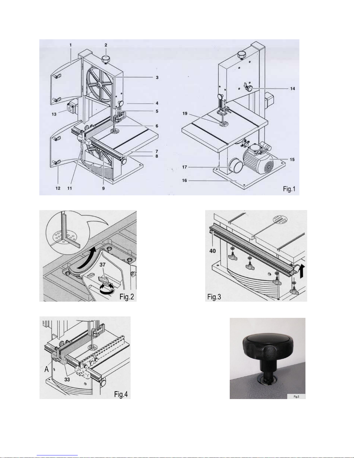
Front side of the machine FIG.1
1. Door of the upper flywheel
2. Knob for the adjustment of bandsaw’s
tensioning FIG.5
3. Blade’s upper flywheel
4. Knob locking for the protection blade
5. Protection
6. Bandsaw’s saw blade
7. Workbench
8. Guiding rail with graduated scale
9. Lower flywheel
11. Rip and trimming fence
12. Door of the lower flywheel
13. ON / OFF switch
Back side of the machine FIG.1
14. Knob for the adjustment of the upper
flywheel
15. Motor
16. Base
17. Dust collection sleeve
18.
19. Bench inlay
Page 15
15
WARNING
Do not start the bandsaw before fastening the machine, assembling and
adjusting the workbench, checking belt tension and safety devices. Only after
performing these tasks you can connect the saw to the power supply. Otherwise the
bandsaw could start suddenly and cause personal injuries.
This machine is delivered almost completely assembled. Before use you must:
I. Fix bandsaw’s base
II. Assemble the workbench
III. Assemble the fence’s rail
IV. Assemble the fence
V. Connect the dust collection device
I. Bandsaw fastening
The bandsaw can be fastened to a surface or assembled on the four legs that are included in
the package. If you want to fix it on a surface:
1. Drill 4 holes on the surface on which you want to fix the bandsaw, while taking into
consideration the base of machine.
2. Use 4 locking devices suitable with the surface and fix the saw.
If you want to use the legs and the bars included in the package, put the machine on its side
and:
1. Assemble the 4 legs to bandsaw’s blade with 8 screws and the corresponding nuts and
washers.
2. Assemble the 8 bars with the screws and the washers.
3. Straighten up the bandsaw.
4. Firmly tighten all the screws.
5. Assemble the two wheels on the two left legs, to make the transport easier.
II. Workbench assembly FIG.2
A. Horizontal adjustment of the workbench
1. Raise the protective cap completely.
2. Check saw blade’s tension and adjust it if it is loose.
3. Loosen the lock screw (37).
4. By using a square, place the workbench at a right angle with the blade and
tighten the locking screw firmly (37).
III. Assembly of fence’s rail FIG.3
Fix fence’s rail (40) on the workbench with 4 wing screws and with washers.
ASSEMBLY OF THE SAW BLADE
Page 16
16
IV. Assembly of the rip fence FIG.4
The rip fence can be assembled on the left and on the right of the saw blade. You can lock the
guide by lowering the lever (A).
V. Connection of the dust collection device
DANGER!
The dust of certain kind of wood, as for example oak, beech or ash-tree has been
proved to be especially dangerous for human health. We recommend you to work
outdoors, to use an efficient dust collection device and personal safety devices as for
example dust masks.
In the bandasaw there is a coupling to which you can connect the pipe of an external dust
collector to extract the dust and wood shavings.
We recommend you to always connect a dust collector when processing wood and to use a
dust mask.
If you do not have a dust collector, we recommend you to work outdoods, with a dust mask
and for short periods of time.
You must periodically remove wood shavings piling up inside the bandsaw and in the pulley’s
compartments.
I. Upper protection of the saw blade FIG.6
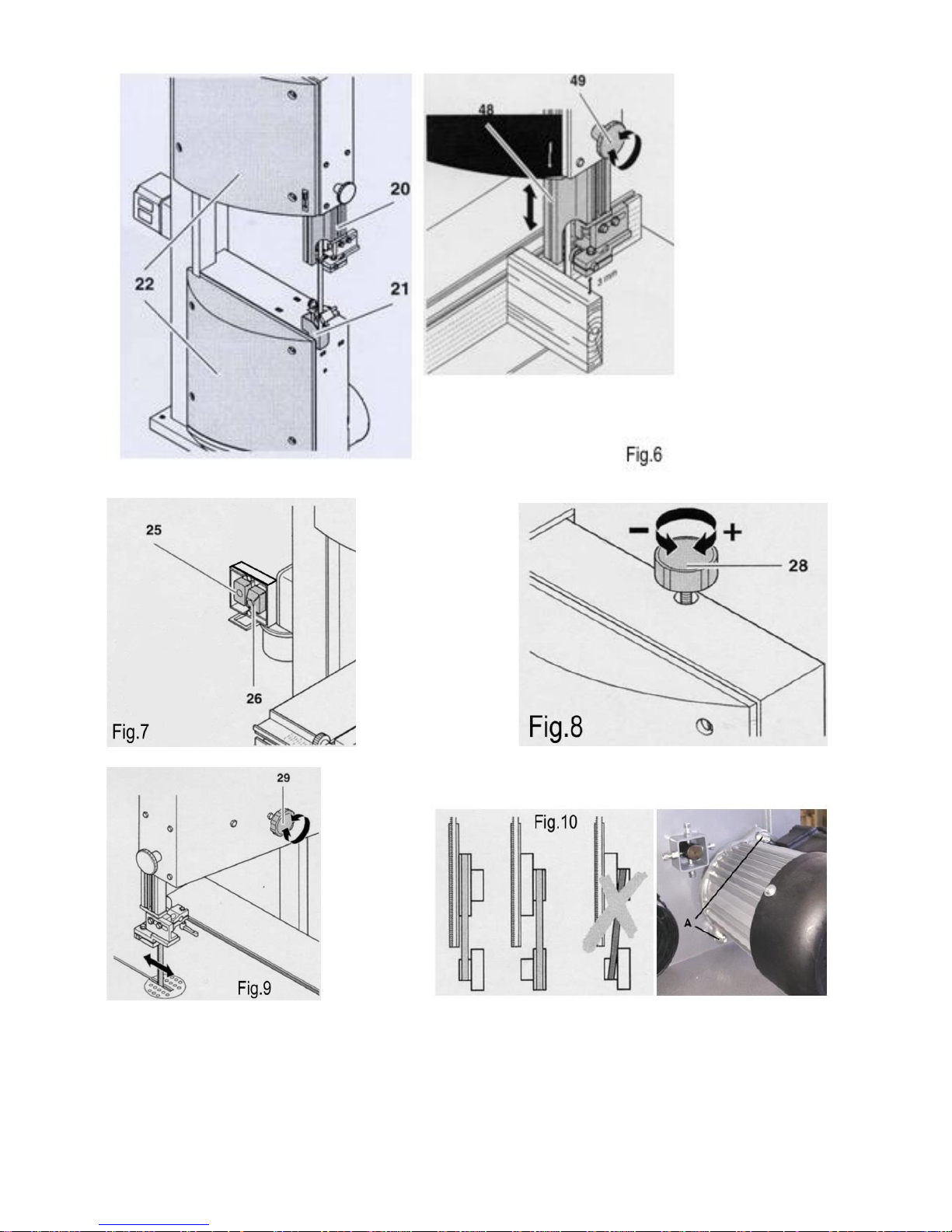
The upper protection of the saw blade (20), which is an integral part of the group including
also the upper blade guide, prevents any unintentional contact with the blade and protects you
the ejection of the shavings. You must always place the upper protection of the blade about 3
mm far from the workpiece in order to ensure the maximum safety degree.
Upper blade guide’s height (48) 1 must be adjusted:
- before any cutting, in order that it is adjusted according to workpiece’s height;
- after any modification of the saw blade or of the workbench (for example, after changing
or tensioning the saw blade, or after adjusting the workbench).
The upper blade guide with its protection (48) is locking of a knob (49). To adjust the height of
this blade guide, grip the blade guide with the left hand, unlocking knob (49) to adjust the
height of the upper blade guide in the desired position.Locking knob (49).
II. Saw blade’s lower protection FIG.6
Saw blade’s lower protection (21) prevents from any unintentional contacts with the blade.
This protection must be moved when you open the lower door. When you close this door this
protection must be replaced in its position to not to compromise general safety. Saw blade’s
lower protection must be always assembled when you are using the machine.
PROTECTION OF THE BLADE
Page 17
17
III. Flywheels’ doors FIG.6
By opening the doors (22) you can get at the flywheels-pulleys to change the blade, remove
the sawdust which has piled up, change the speed by moving the belt on the pulleys. When
using the machine, these doors are safety devices that isolate moving parts that could be
dangerous.
To open and close the doors, give the locking devices a quarter of a turn by using a suitable
flat screwdriver.
IMPORTANT:
Bandsaw’s two doors must be always closed when the machine is in use. It is forbidden
to start the machine if these two doors are open.
WARNING!
Before performing any adjustment or maintenance task and before changing the
blade you must switch off the machine, disconnect it from the power supply and wait
for the saw blade to stop.
CAUTION
Connect the bandsaw to the electrical energy and start it only after checking that
the machine is fastened, that the workbench is assembled and adjusted, that saw blade
tensioning is correct and that all safety and protection devices are perfectly efficient.
I. ON / OFF switch FIG.7
Start = push the green button (25).
Stop = push the red button (26).
In case of an interruption of the electrical energy, a “minimum voltage” relay inside the switch
stops the machine. This prevents from the start of the machine when the electrical energy
recovers. You must press the green button to re-start the saw that has stopped.
FUNCTIONING
Page 18

18
II. Saw blade’s tension FIG.8
WARNING!
A too high tension can break the saw blade. If the tension is too low, the saw
blade can slip from the driving wheel and stop.
Saw blade’s tension must be adjusted according to the different width of the saw blades in
order to obtain a correct alignment, efficiency and suitable life’s length.
Lift the upper blade guide completely.
To check blade’s tension, push sideways the saw blade, in the middle between the
workbench and the upper blade guide: the saw blade must bend on its side from 1 to a
maximum of 2 mm.
If necessary, adjust saw blade’s tension:
turn the handle 28 clockwise to increase the tension;
turn the handle 28 anti-clockwise to reduce the tension.
III. Knob for the adjustment of the blade’s position FIG.9
To work correctly the saw blade must be centred on flywheel rubber coatings. If it is not aligned
you must modify upper flywheel’s inclination. By using the knob ( 29 ) you can modify the
inclination of the flywheel and thus:
Turn the knob clockwise to move the blade backwards.
Turn the knob anti-clockwise to move the blade forwards.
To lock upper flywheel’s inclination, tighten the plastic wing screw located under the
adjustment knob.
IV. Speed adjustment FIG.10
By moving the belt on the engine and flywheel pulleys you can use the bandsaw at two different
speeds.
Inside the lower door there are some instructions explaining how to place the belt to obtain
two different speeds.
1. Open the lower door with a screwdriver.
2. Loosen the screws motor indicated
3. Loosen the belt by turning the motor unclockwise.
Move the belt on the desired position, tighten the belt again and close the lower door
by using a screwdriver.
- SMALL ENGINE PULLEY – LARGE FLYWHEEL PULLEY: blade speed 660 m/min,
suitable for hard wood types, plastics and metal materials (by using a suitable saw
blade).
- LARGE ENGINE PULLEY – SMALL FLYWHEEL PULLEY: blade speed 960 m/min for
all soft wood types.
Caution!
Do not place the belt obliquely, since it would suffer damages.
Page 19
19
V. Adjustment of workbench’s inclination FIG.2
The workbench can be moved from 0 and 45°. To move it, loosen the lock screw (37), move
the workbench to the desired angle and tighten the screw (37).
VI. Rip fence FIG.4
The rip fence (33) can be assembled both on the left and on the right of the saw blade. Choose
the position by using a graduated scale, place the guide and lock it by lowering the front lever
A.
VII. Cutting
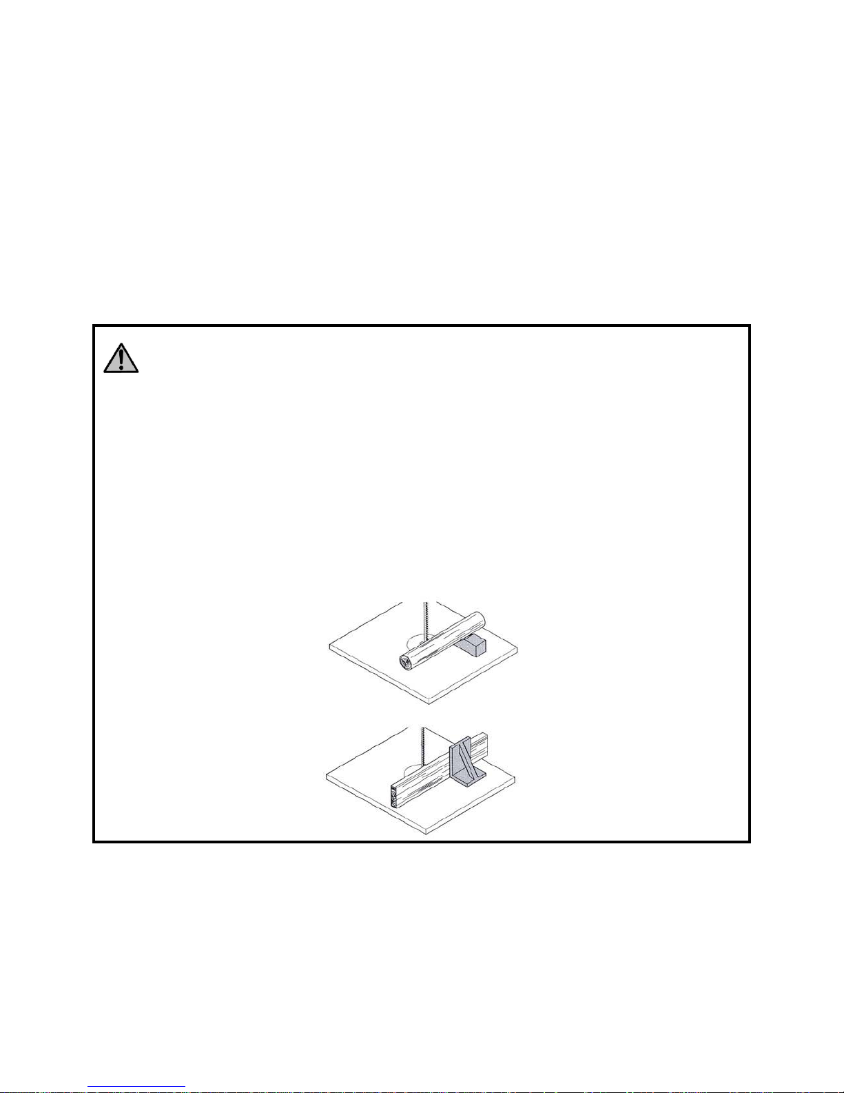
DANGER!
To reduce the risk of injuries, respect the following safety regulations during any
kind of processing:
- use personal safety equipment;
- saw only one piece at a time;
- when cross cutting, always press the workpiece against the workbench;
- do not slow down the saw blade by exerting a side pressure on it;
- For all kinds of work and according to your necessities always use:
+ a pusher if the distance between the rip fence and the saw blade is less
than or equal to 120 mm;
+ a support surface for long pieces if they risk to fall from the workbench
after being cut;
+ a dust collection device;
+ a suitable locking device, in order that the piece cannot rotate crosswise.
+ a square with suitable stops to prevent the piece from bending.
Maintain a correct working position when using the machine (saw blade’s teeth must
point towards the operator and downwards).
Do not pile the pieces to cut them. If they get caught by the blade uncontrollably risks
may arise for the operator.
Never cut pieces fastened with ropes, strings, cables or wires, or containing these
materials.
1. Be sure of the perfect conditions of the saw blade and of the protection devices.
2. If necessary, adjust workbench’s inclination.
Page 20
20
3. Place the rip fence according to the type of cutting you want to carry out, or choose the
outline of the support for the piece to be cut.
4. Position and lock the upper blade guide at a distance of 3 mm over the workpiece.
5. Select blade speed.
6. Before starting working, do a shear test on a piece.
7. Connect the bandsaw to the power supply and switch on the machine.
8. Place the piece on the workbench.
9. Cut one piece at a time.
10. Once you have finished cutting, switch off the machine, disconnect from the power
supply and clean it.
I. Replacement of the saw blade FIG.11 – 12
DANGER!
Before performing any adjustment or maintenance task and before changing
the blade you must switch off the machine, disconnect it from the power supply and
wait for the saw blade to stop.
DANGER!
The risk of cut exist also when the saw blade is still. When changing the saw
blade, wear protective gloves. Use only suitable blades.
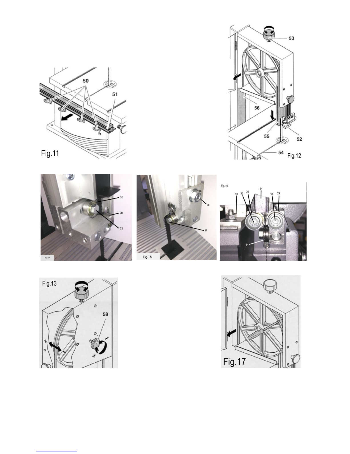
1. Loosen the 4 wing nuts (50) and remove the rail of the rip fence (51).
2. Open the two doors with a screwdriver.
3. Place the upper blade guide (52) in its lowest position.
4. Turn the adjustment knob (53) until when the saw blade is loose.
5. Remove the saw blade and let it pass through the bench hole, the upper and lower blade
guides.
6. Insert a new blade. Pay attention to the position of the blade: teeth must point towards
the operator and downwards.
7. Place the blade in the middle of flywheels rubber coatings.
8. Turn the tensioning knob clockwise to tighten the saw blade.
9. Close the two doors.
10. Then:
adjust the saw blade if necessary;
adjust the blade guides;
let the blade turn for at least a minute;
switch off the machine, remove the plug from the socket
and check the adjustment of the blade guides
ASSEMBLY OF THE BLADE AND ADJUSTMENTS
Page 21
21
II. Adjustment of the saw blade FIG.13
The saw blade must be perfectly centred on the rubber coatings of the flywheels. If it is not the
case, you must change the upper flywheel inclination:
1. Loosen the lock nut (57).
2. Turn the adjustment screw (58):
Turn the adjustment screw (58) clockwise when the saw blade tends to move
frontally.
Turn the lock screw (58) anti-clockwise when the saw blade tends to move
backwards.
3. Tighten firmly the lock nut (57).
UPPER SAW BLADE GUIDE ADJUSTMENT FIG.14 - 15
Upper saw blade guide is composed of :
- a support bearing (30) Fig.14 (which support the blade from the back),
- two wheels (28) Fig.14 (which guide the blade sideways).
The support bearing and the side wheels must be adjusted each time the blade is replaced or adjusted.
Note: Check regularly if the wheels are worn out, and if necessary, replace them both at the same moment.
Loosen screw (33) Fig.14 to free support bearing (30) in order that there is a gap of maximum 0,5 mm between
it and the saw blade.
1. Tighten screw (33).
2. Loosen hex head screw (35) Fig.15.
3. Move the part (36) in order that the wheels (28) are about 1 mm behind teeth's base.
4. Tighten firmly screw (35)
5. Loosen hex head screws (37).
6. Push the two wheels (28) in the direction of the saw blade until they come in contact with the saw blade
(saw blade musn't get stuck).
7. Tighten hex head screws (37).
8. Make the upper wheel rotate clockwise by hand in order to place the wheels correctly (they must touch
lightly the saw blade).
LOWER SAW BLADE GUIDE ADJUSTMENT FIG.16
Lower saw blade guide is composed of :
- a support bearing (31) Fig.16 (which support the blade from the back),
- two wheels (29) Fig.16 (which guide the blade sideways).
The support bearing and the side wheels must be adjusted each time the blade is replaced or adjusted.
Note: Check regularly if the wheels are worn out, and if necessary, replace them both at the same moment.
1. Disassemble the workbench (7) Fig.1.
2. Move the saw blade protection (34) backwards.
3. Lower support bearing adjustment can be carried out by following the same instructions regarding upper
support bearing adjustment.
The two support bearings (30) and (31) Fig.9 support the saw blade (26) only during cutting operations. When
the machine works in no-load condition, the saw blade mustn't touch the ball bearings.
4. Loosen hex head screw (40)
5. Move the part (49) in order that the wheels (29) are about 1 mm behind teeth's base. Tighten firmly screw
(40).
6. Loosen hex head screws (38) .
Page 22

22
7. Push the two wheels (29) in the direction of the saw blade until they come in contact with the saw blade
(saw blade musn't get stuck).
8. Tighten hex head screws (38).
9. Make the upper wheel (7) rotate clockwise by hand in order to place the wheels correctly (they must
touch lightly the saw blade).
10. After finishing adjustment operations, close the saw blade protection (34).
DANGER!
Before performing any adjustment or maintenance task and before changing
the blade you must switch off the machine, disconnect it from the power supply and
wait for the saw blade to stop.
I. General regulations
In case you find out any damage to the protection devices or irregularities while processing or
checking the machine, you must get it repaired immediately by qualified persons.
Before use check that the protection and safety devices are perfectly efficient. After carrying
out the work, make a general cleaning of the machine by removing dust and chips.
Do not use any thinner to clean plastic pieces. Most of the kinds of plastic risk to get damaged
by commercially available thinners. Use a clean cloth to remove impurities, dust, etc.
Extract periodically sawdust that can pile up inside the machine by opening the two doors.
Clean also the ventilation inlets of the engine.
Be sure that the protective cap can slide freely.
Periodically check the tensioning and the conditions of the belt.
Periodically check the conditions of the flywheels’ coatings.
Periodically check bench inlay’s conditions.
II. Replacement of the flywheels’ coatings FIG.17
Regularly check the flywheels’ coatings and if necessary change both of them:
1. remove the saw blade (see previous paragraphs);
2. let a small screwdriver slide under the coatings and remove them;
3. place the new plastic coatings and re-assemble the saw blade.
III. Replacement of the bench inlay
The bench inlay must be changed when the hole for the passage of the blade is damaged.
1. remove the bench inlay (80) from the workbench by pushing from below.
2. Insert a new bench inlay.
Page 23
23
DANGER!
Before performing any tasks after a failure:
- Switch off the machine.
- Remove the plug from the socket.
- Wait for the saw blade to stop.
After any intervention, replace all safety devices and check them.
The engine does not work
A possible tension reduction has made the minimum voltage relay start.
- Re-start the machine.
There is not any supply voltage:
- Check the cable, the socket and the switch.
Saw blade moves away the cutting line or decentralizes itself
The saw blade is not centred on the driving wheel:
- Modify the upper flywheel inclination (see par. “Adjustment knob”).
The saw blade has broken
Saw blade tension is unsuitable:
- Adjust saw blade’s tension (see par. “Saw blade tension”).
The forcing is too high:
- Reduce the pressure exerting against the saw blade.
The saw blade is inadequate:
- Change the saw blade (see par. “Replacement of the blade”):
If you must cut a thin workpiece, you must use a thin saw blade.
If you must cut a wide workpiece, you must use a wide saw blade.
The saw blade is misshapen
The forcing is too high:
- Do not force sideways on the saw blade.
The saw blade stops
The forcing is too high:
- Reduce the pressure you are exerting on the workpiece.
- Check the sharpness and the kind of blade.
Machine vibrations:
Insufficient fastening:
- Firmly fasten the bandsaw to the ground (see par. “bandsaw fastening”)
The workbench is loose:
- Place the workbench and fix it. (see par. “assembly of the workbench”)
The motor is loose:
- Check the lock screws and tighten them if necessary.
The aspiration coupling is obstructed
No dust collection device is connected or the aspiration leg is too small.
- Connect the dust collection device or increase aspiration power (air speed ≥ 20
- m/sec at the degree of the dust collection coupling).
MALFUNCTIONS
Page 24

24
All the tools and accessories are made and checked by using the safest and most modern
productive methods. However, if a tool gets damaged, it must be repaired by an authorised
after sales centre.
You can sending a request to the e-mail address [email protected].
AFTER SALES SERVICE
Page 25
25
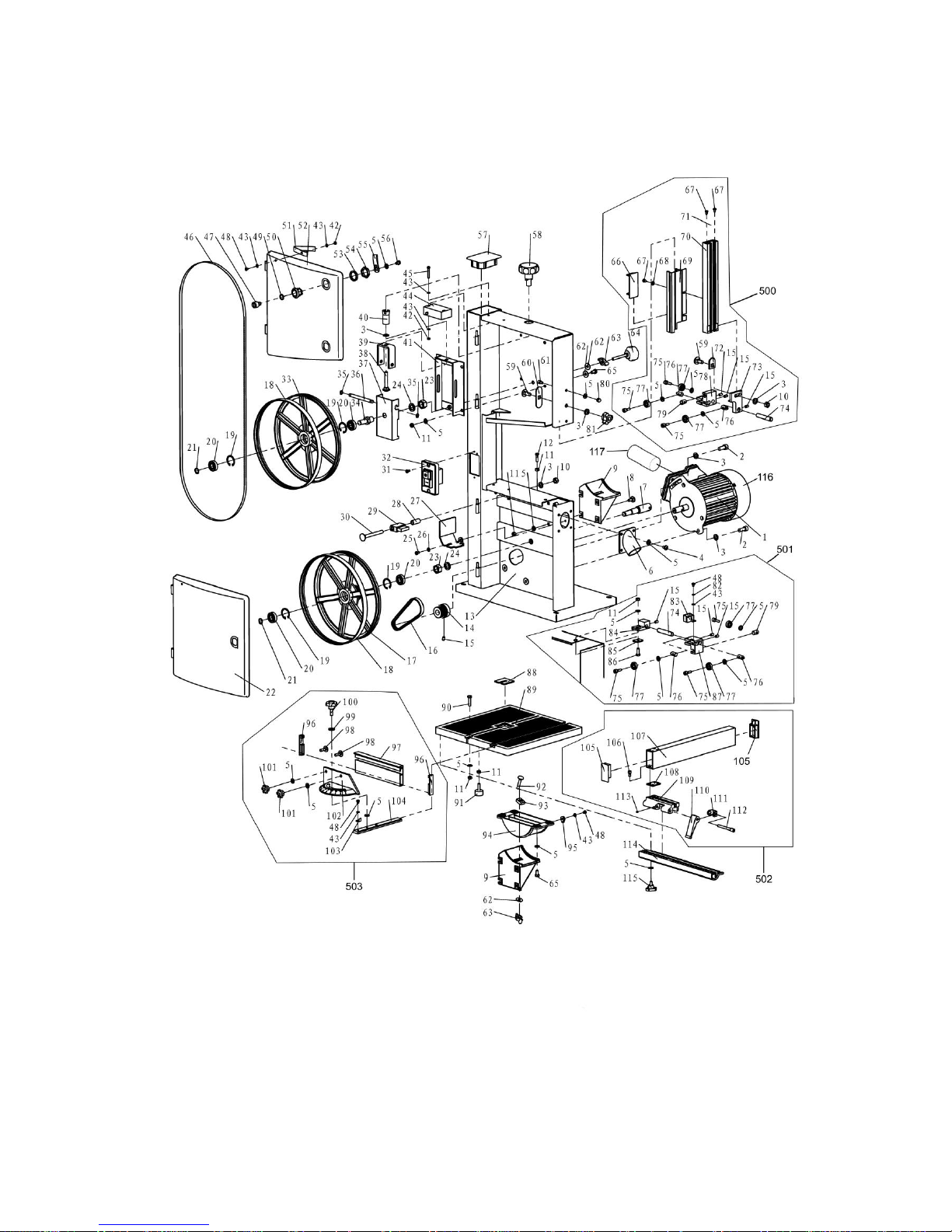
EXPLODED VIEW
Page 26

26
N.
Art. / Item
N.
Art. / Item
N.
Art. / Item
N.
Art. / Item
1
F28186A-1
55
F28186A-55
109
F28186A-109
2
F28186A-2
56
F28186A-56
110
F28186A-110
3
F28186A-3
57
F28186A-57
111
F28186A-111
4
F28186A-4
58
F28186A-58
112
F28186A-112
5
F28186A-5
59
F28186A-59
113
F28186A-113
6
F28186A-6
60
F28186A-60
114
F28186A-114
7
F28186A-7
61
F28186A-61
115
F28186A-115
8
F28186A-8
62
F28186A-62
116
F28186A-116
9
F28186A-9
63
F28186A-63
117
F28186A-117
10
F28186A-10
64
F28186A-64
500
F28186A-500
11
F28186A-11
65
F28186A-65
501
F28186A-501
12
F28186A-12
66
F28186A-66
502
F28186A-502
13
F28186A-13
67
F28186A-67
503
F28186A-503
14
F28186A-14
68
F28186A-68
15
F28186A-15
69
F28186A-69
16
F28186A-16
70
F28186A-70
17
F28186A-17
71
F28186A-71
18
F28186A-18
72
F28186A-72
19
F28186A-19
73
F28186A-73
20
F28186A-20
74
F28186A-74
21
F28186A-21
75
F28186A-75
22
F28186A-22
76
F28186A-76
23
F28186A-23
77
F28186A-77
24
F28186A-24
78
F28186A-78
25
F28186A-25
79
F28186A-79
26
F28186A-26
80
F28186A-80
27
F28186A-27
81
F28186A-81
28
F28186A-28
82
F28186A-82
29
F28186A-29
83
F28186A-83
30
F28186A-30
84
F28186A-84
31
F28186A-31
85
F28186A-85
32
F28186A-32
86
F28186A-86
33
F28186A-33
87
F28186A-87
34
F28186A-34
88
F28186A-88
35
F28186A-35
89
F28186A-89
36
F28186A-36
90
F28186A-90
37
F28186A-37
91
F28186A-91
38
F28186A-38
92
F28186A-92
39
F28186A-39
93
F28186A-93
40
F28186A-40
94
F28186A-94
41
F28186A-41
95
F28186A-95
42
F28186A-42
96
F28186A-96
43
F28186A-43
97
F28186A-97
44
F28186A-44
98
F28186A-98
45
F28186A-45
99
F28186A-99
46
F28186A-46
100
F28186A-100
47
F28186A-47
101
F28186A-101
48
F28186A-48
102
F28186A-102
49
F28186A-49
103
F28186A-103
50
F28186A-50
104
F28186A-104
51
F28186A-51
105
F28186A-105
52
F28186A-52
106
F28186A-106
53
F28186A-53
107
F28186A-107
54
F28186A-54
108
F28186A-108
Page 27
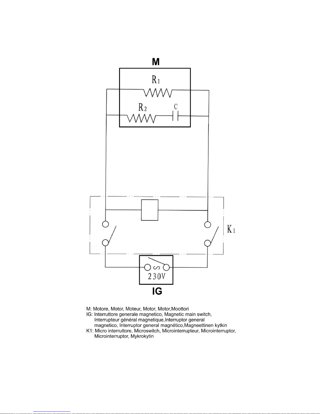
WIRING DIAGRAM
Page 28
DECLARATION OF CONFORMITY
in accordance with EU Directive 2006/42/EC, Annex II, Part A
FEMI SpA
Via del Lavoro, 4
40023 Castel Guelfo - (BO) ITALY
hereby declares that the machine:
VERTICAL BANDSAW Art: F28-186A
manufactured in: (see label)
conforms to the provisions of Machinery Directive 2006/42/EC and all provisions of implementation.
furthermore it also conforms to the following provisions and relative implementation; 2006/95/EC, 2004/108/EC,
2011/65/UE,2012/19/UE.
EN 61029-1/A11:2010,EN 61029-2-5:2011
EN 55014-1/A2:2011
EN 55014-2/A2:2009
EN 61000-3-2/A2:2009
EN 61000-3-3:2008
Castel Guelfo (BO) Italy 28/10/2015
Il Presidente del Consiglio
The Director
40023 CASTEL GUELFO (BO) ITALY
Via del Lavoro, 4
Tel. +39-0542/487722 Fax +39-0542/488226
E-Mail: [email protected] – www.fox-machines.com
 Loading...