

Page 1

1
DRILL PRESS
Fox model
F12-942A
USER MANUAL
Page 2

2
Drill press (FOX model F12-942A)
TABLE OF CONTENTS
Safety instructions 3
General safety instructions 4
Specific safety instructions for drill presses 6
Environment protection 7
Symbols 7
Electrical connections 8
Recommended use 9
Technical specifications 9
Noise conditions 9
Removal of package 10
Drill press assembly 11
Drill press description 15
Drilling speed 17
Starting the drill press 17
Use 17
Maintenance 17
Trouble shooting 18
After-sales service 18
Page 3

3
CAUTION:
Besides following the instructions mentioned in this manual, when using electric equipment you must
always observe all safety precautions to prevent risk of fire, electric shock and personal injury.
Read this instruction manual before use and keep it carefully.
Working with an electric machine can be dangerous if you do not follow suitable safety measures. As for
any electric machine with moving parts, the use of a tool entails some risks. If you use the machine as
prescribed in this manual, you pay careful attention to the work you are doing, you observe the regulations
and you use the suitable personal devices of protection, you can reduce the probability of risk. The
possible remaining risks are related to:
1 – direct or in direct contacts with electrical shock
2 – injuries due to contact with moving parts
3 – injuries due to contact with angular parts
4 – injuries due to the ejection of tool parts or of the material you are processing
5 – injuries due to noise
The probability of risk can be reduced by the machine safety equipment of the machines, as for example
the protections, the blade case, the clamping, the stoppage and the personal protection devices as
protective goggles, the dust mask, ear plugs, protective shoes and gloves. However, even the best
protection devices cannot protect you from the risks due to lack of good sense and attention. Have always
good sense and observe the necessary precautions. Carry out only the operations that you consider safe.
DO NOT FORGET: everyone is responsible for his safety.
This tool has been designed for specific purposes. We recommend you not to modify it or use it for
purposes different from the ones for which it has been manufactured. If you have any doubts regarding
specific applications, do not use the machine before having contacted us and received our instructions.
READ AND KEEP THIS MANUAL
SAFETY INSTRUCTIONS
Page 4

4
1. Keep the work surface clean. If the work area or surface is busy the probability of injuries is
higher.
2. Do not use the machine in dangerous environment conditions. In order to prevent electric shock, do
not expose the machine to rain and do not use it in a damp area. Keep the work area illuminated.
Do not use the machine near gas or inflammable substances.
3. Connect the dust collection device. If the machine is provided with a dust collection device, make
sure that this system is connected and correctly used.
4. Keep unknown persons and children away from the machine. All unknown persons and children
must keep a safe distance from the work area.
5. Protect yourself from electric shock. Avoid any contact with earthing surfaces.
6. Handle the power supply cable with care. Do not pull the electric cable to disconnect it from the
plug. Keep the electric cable away from heat, oil and sharp edges.
7. Use extension cables designed for outdoor use. When using the machine outdoors, use only
extension cables suitable for outdoor use, having specific indications.
8. Be vigilant. Check carefully what you are doing, have good sense. Do not use the machine if you
are tired.
9. Do not use the machine if you are have taken medicines, alcohol, drugs.
10. Avoid accidental starts. Be sure that the switch is on the OFF position before inserting the plug into
the socket.
11. Wear appropriate clothing. Do not wear loose-sleeved garments or pieces of jewllery which may
get caught in the moving parts. For outdoor use we recommend non-slip shoes. Use headgear to
cover hair if necessary.
12. Use always personal protection devices: wear protective goggles and masks in case dust or
sawdust is produced. Wear ear muffs or plugs in noisy areas. Wear gloves when handling parts with
sharp edges.
13. Keep your balance over the machine. Always keep stand firmly.
14. Ask for advices to expert and qualified people if you are not familiar with using such a machine.
15. Remove the tools you do not use from the workbench. If you do not use the tools, you must arrange
them in a dry area which is locked and away from the reach of children.
16. Do not force the machine. You can obtain better and safer results if you use the machine at the rate
for which it has been designed.
17. Use the suitable tool. Do not use a small tool for an intensive job. Fox example, do not use a
circular saw to cut branches or stumps.
18. Block the piece. If possible, use C-clamps or a holder to fix the piece. It is safer than using only your
hands.
GENERAL SAFETY INSTRUCTIONS
Page 5

5
19. Keep the tools in perfect conditions. Keep the tools sharp and clean to obtain better and safer
results. Follow the instructions to grease and change the accessories. Check regularly the electric
cable and change it if it is damaged. Keep the handles and the handgrips dry, clean, unoiled and
ungreased.
20. Disconnect the tool from electricity if you do not use it, before maintenance and change of the
accessories or tools such as blades, drills, mills, etc.
21. Remove locking and adjustment wrenches from the workbench. Get used to check if the locking and
adjustment wrenches have been removed before starting it.
22. Check the parts of the tool to verify that there are not any damages. Before using the machine,
check if the safety devices or any other parts are damaged in order to be sure that it works properly
and that it can accomplish the tasks for which it has been designed. Check that the moving parts are
aligned, do not stop and are not broken. Check the assembly and any other condition that can
influence the functioning of the machine. Any part or protection damaged must be repaired or
changed from an authorized after sales centre. Do not use the machine if the switch does not work
properly.
23. Use the machine, the tools and accessories in the way and for the purposes mentioned i this
manual. Different uses and parts can cause possible risks for the operator.
24. Get the machine repaired by a qualified person. This electric tool is in compliance with local safety
regulations. The machine must be repaired only by qualified people who use original spareparts,
otherwise risks may arise for the operator.
Page 6

6
1. DO NOT use the drill press until it is completely assembled and installed according to the
instructions of this manual.
2. FIX the drill press on a supporting or flat surface. If the supporting or the flat surface move during
use, FIX them to the ground.
3. START the drill press after removing all objects (tools, discards, etc..).
4. DO NOT start the drill press when the bit is in contact with the workpiece.
5. ONLY USE bits, tools or other accessories provided with a spindle connection pin smaller than
13mm.
6. ALWAYS KEEP your hands and fingers away from the bit or the tool.
7. DO NOT TRY to drill a workpiece which does not have a flat surface, unless you use a suitable
horizontal base.
8. ALWAYS USE a locking device to prevent the workpiece from turning during working.
9. USE recommended speeds to drill the various materials according to the bit you are using.
10. BE SURE that all locking handles are locked before starting the machine and that the transparent
protection of the spindle is in its position.
11. DO NOT carry out any assembly or preparation tasks on the workbench when the drill press is
working.
12. BE SURE that the bit or the tool are not damaged and that they are properly blocked in the spindle
before use.
13. BE SURE that the wrench of the spindle has been removed from the spindle before starting the
machine. Only use the spindle wrench provided with the drill press.
14. ADJUST workbench’s height and bit’s descent depth in order to prevent the bit from drilling the
workbench.
15. ALWAYS switch off the machine before removing the chips from the workbench.
16. BE SURE that big workpieces are correctly supported at workbench’s height during cutting.
17. DISCONNECT THE MACHINE FROM THE POWER SUPPLY, remove the bit or the tool before
moving away from the machine.
18. REPLACE the missing or damaged parts. Do not use the drill if all its parts do not work.
1. USE the recommended drilling speed for the specific operation you are carrying out and for the
material you are drilling. To do this, check the inside part of the pulley cover to see how to properly
position the belt.
SPECIFIC SAFETY INSTRUCTIONS FOR DRILL PRESSES
Page 7
7
INFORMATION FOR USERS
“Implementation of Directives 2011/65/UE, 2012/19/UE, relative to reducing the use of hazardous
substances in electric and electronic appliances and the disposal of waste”, please take note of the
following:
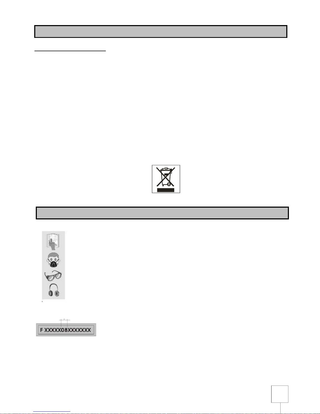
The crossed out wheelie bin symbol found on the appliance or the packaging indicates that the
product must be disposed separately from ordinary household waste when it reaches the end of its
working life.
The user must consign the unwanted appliance to an authorised waste disposal centre for electric
and electronic goods, or alternatively, hand it over to the relative dealer at the moment of
purchasing a new appliance of the same type on a basis of a one to one ratio.
Differentiated disposal to enable possible recycling or environmentally compatible elimination of
the appliance, helps to limit undesirable effects on health and environment and promotes the reuse
and/or recycling of the materials that compose the appliance.
WARNING!
In accordance with the relative legislation in force in the country of use, sanctions will be imposed
on the user if the appliance is disposed of illegally.
Read the instruction manual carefully
Use personal protection devices (goggles, dust mask earphones)
Serial number / year of production
ENVIRONMENT PROTECTION
SYMBOLS
Page 8
8
ELECTRICAL CONNECTIONS
Use 230 V 50 Hz alternate voltage equipped with a earthing conductor to supply your machine. Ensure
that the power supply corresponds to this voltage, that it is protected by a differential and
magnetothermal switch, and that the earthing system is efficient. If your machine does not work when
connected to a socket, check carefully the power supply features.
Use an extension cable in order to connect the machine to the power supply.
EARTHING INSTRUCTIONS
If the tool does not work properly or in case of short-circuit, the earthing system provides the current with
a less resistance path and reduces the risk of electric shock. This tool has a plug to which a supply or
extension cable must be connected, which in turn must be connected to a socket correctly installed and
earthed, in conformity with local standards and regulations. Be sure that your earthing system is in good
conditions and that your plug is protected by a differential and magnetothermal switch.
Do not modify the plug of the machine. If it does not enter the socket, get a suitable plug installed by a
qualified person. If the earthing conductor is not correctly connected the risk of electric shock can occur.
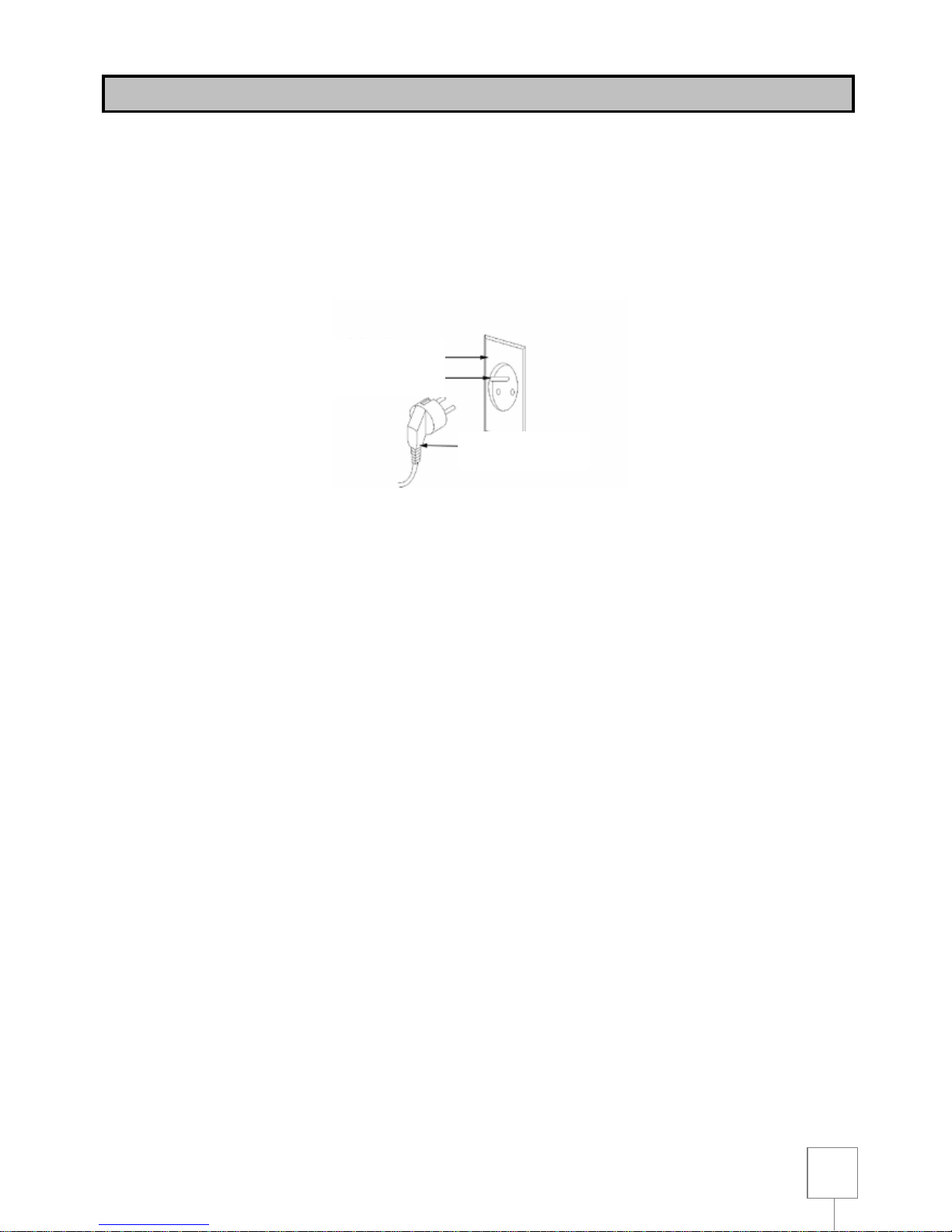
The conductor which has the green insulating jacket (with or without a yellow line) is the earthing
conductor. If you must repair or change the supply cable, do not connect the earthing conductor to a low
tension terminal.
Consult a qualified electrician or a person in charge of the maintenance if you have not understood or
you have some doubts on the earthing instructions.
If the supply cable is damaged it must be changed by qualified people. Do not switch on the machine if
the supply cable is damaged.
This tool is provided with a plug which must connected to a suitable socket.
EXTENSION LEADS
Only use three conductors extension leads, with a plug with two plugs and a earthing contact and
sockets with two holes and a earth corresponding to the plug of the tool. When using an electric tool at a
remarkable distance from the power supply, use an extension lead with sufficient dimensions to
transport the current which the tool needs. If the extension cable has not the sufficient dimensions a
voltage drop can occur, thus causing an overheating and a voltage loss. You can only use extension
leads which are in compliance with CE standards.
Extension lead length: up to 15 m
Cable dimensions: 3 x 2,5 mm²
Before using any kind of extension lead, check that it has not bare wires and that the insulation is not cut
or worn. Repair and change immediately it if it is damaged or worn.
Socket with earthing
system
Earth conductor
Machine’s plug
ELECTRICAL CONNECTIONS
Page 9
9
WARNING:
Extension cables must be arranged away from the working area in order that they do not get in contact
with the workpieces, the tool or other parts of the machine, thus creating possible risks.
WARNING:
KEEP THE TOOLS AND THE EQUIPMENT AT A SAFE DISTANCE FROM CHILDREN
This tool has been designed for drilling steel, metals, wood, plastics and all kind of materials in general,
except for hardened steel, by using suitable bits and by selecting the suitable speed according to the
material you are cutting and the tool you are using.
F12-942A
Motor power:
450 W
Speed:
210-2220 min-1
Drill bit dimensions:
3 - 16 mm
Max drilling capacity:
16 mm
Chuck – column distance:
169 mm
Chuck stroke:
80 mm
Workbench dimensions:
270 x 270 mm
Morse cone:
MT2
Height:
990 mm
Net weight:
53 kg
The noise emitted, measured in conformity with the standards EN 3744 and EN 11201 is:
- Sound pressure level LpA = 63.4 dB(A)
- Sound power level LWA = 79.4 dB(A)
- Uncertainty of measurement K = 3 dB.
Noise levels are emission levels and do not necessarily indicate safe working conditions. Even if there is a
connection between emission levels and exposure levels, the first ones cannot be used to determine
safely if other precautions are necessary. The factors that can influence the actual exposure level of the
operator include exposure length, environment features and other sources of noise, as for example the
number of machines and operations present. Besides, exposure levels can change from country to
country. However, these instructions enable the user of the machine to better evaluate the dangers and
risks.
Drill press noise emission is very low and thus not dangerous for the user, however, if other tools are
working or in case of noisy environment ear protection devices could be necessary.
TECHNICAL SPECIFICATIONS
RECOMMENDED USE
NOISE CONDITIONS
Page 10
10
Your drill press is delivered complete inside the package. Remove the package carefully and check that
nothing is missing or damaged.
In case there are any faulty or damaged parts, do not use them in order not to compromise tool efficiency
and safety. Address to an after sales centre to replace faulty parts.
To make the drill press work perfectly you have to assemble the various parts.
We recommend you to read carefully the assembly instructions and to follow them to the letter.
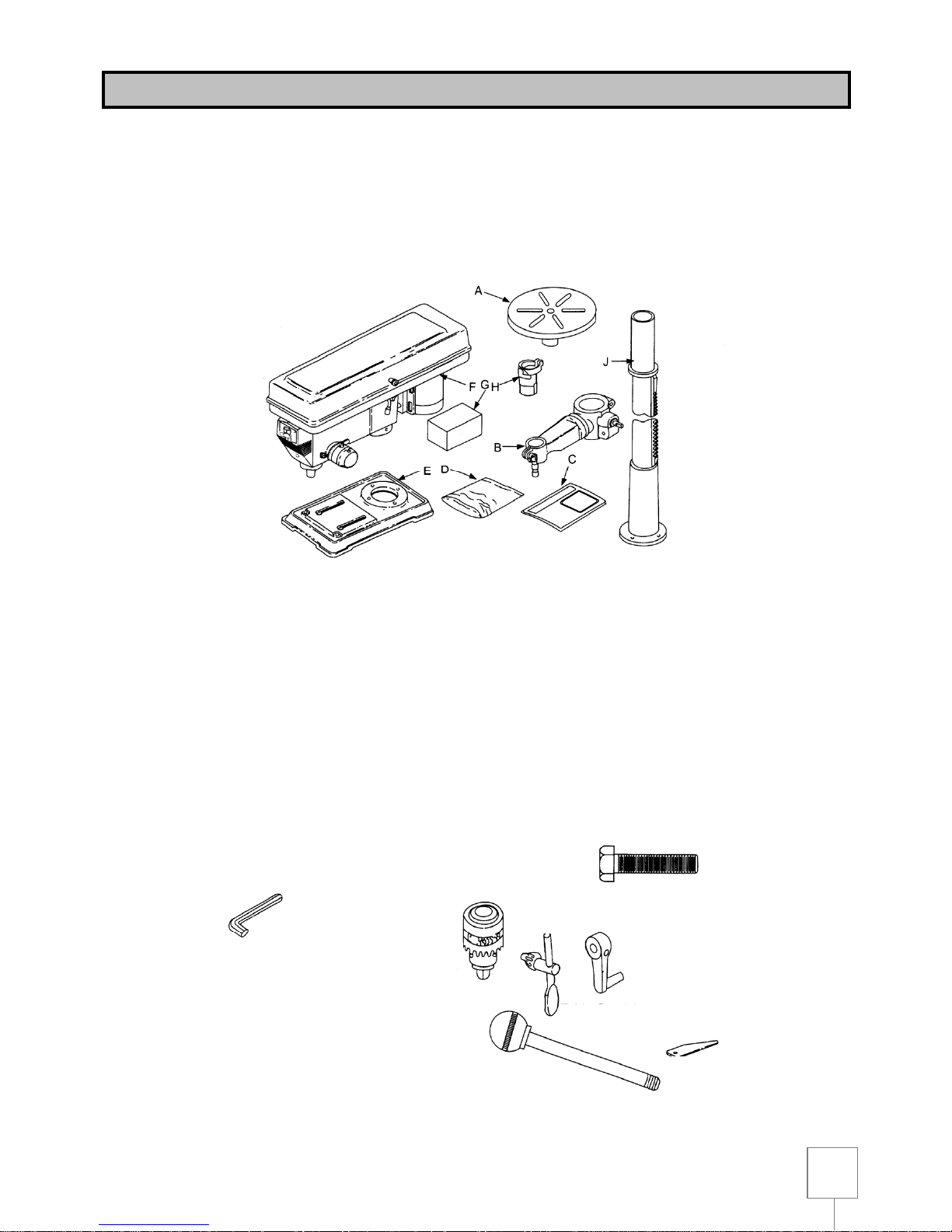
Drill press package includes:
A) Table
B) Arm
C) Manual
D) Bag with loose parts
E) Base
F) Head assembly
G) Box of loose parts
H) Chuck guard
I) Column
LOOSE PARTS IN BAG AND BOX
REMOVAL OF PACKAGE
Allen key (3)
Idler pulley
Chuck
Chuck key
Hex head screws (4)
Table crank
Support lock
handle
Wedge drift
V belt (2)
Pulley cover knob
Pan head screw M5
Handle
Page 11
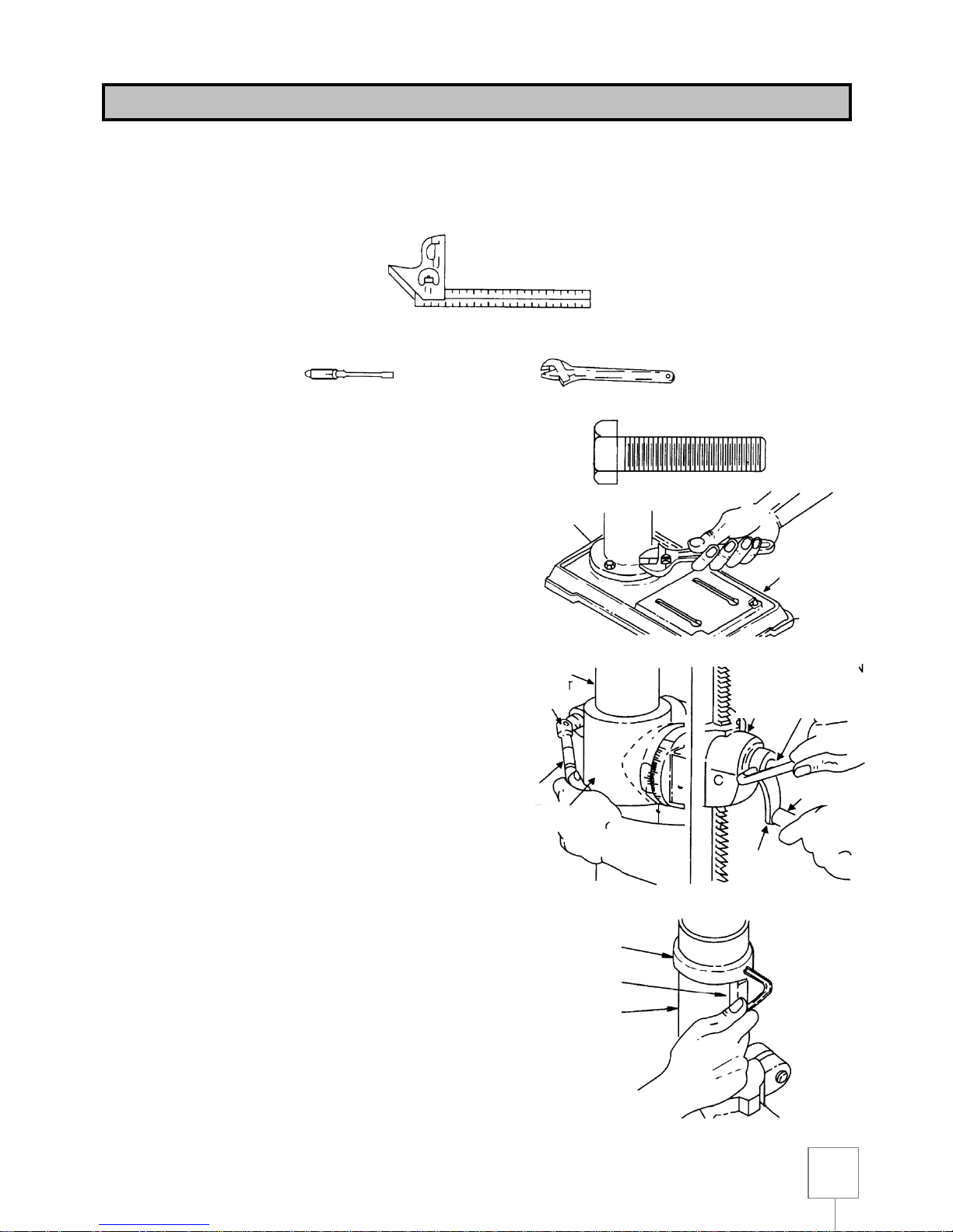
11
WARNING: FOR YOUR OWN SAFETY, NEVER CONNECT PLUG TO POWER SOURCE OUTLET
UNTIL ALL ASSEMBLY STEPS ARE COMPLETED.
TOOLS NEEDED:
ASSEMBLY OF COLUMN AND TABLE HARDWARE
1. Position the base on the floor. Remove the
protective cover.
2. Remove the protective sleeve from the column
tube. Place the column assembly on the base,
and align the holes in the column support with the
holes in the base.
3. Locate four D 10mm x 40 mm long bolts (see
illustration) in loose parts bag.
4. Install a bolt in each hole through the column
support and the base and tighten with the
adjustable wrench.
5. Locate table crank and support lock in loose parts
box.
6. Install support lock from left side into the table
support and tighten by hand.
7. Install table crank assembly and tighten set screw
with a 3mm hex “L” wrench. Do not overtighten.
Set screw should be tightened against the flat
section of the shaft.
NOTE: To minimize crank backlash, tighten the
support lock, rotate the elevation worm shaft
clockwise, then assemble crank tight against table
support and tighten set screw.
8. Check column collar for proper adjustment. Collar
should not be angled on the column and it should
be positioned so that the rack can slide freely in
the collar when the table is rotated 360° around
column table. If re-adjusted, only tighten set screw
enough to keep collar in place.
NOTE: To avoid column or collar damage, do not
overtighten set screw.
DRILL PRESS ASSEMBLY
Combination
square
Adjustable wrench
Medium screwdriver
Column
support
D 10mm x 40 mm
long bolt
Base
Column
Support
lock
Table support
Table support
Elevation
worm shaft
Table crank
Handle
Column collar
Rack
Column
Page 12

12
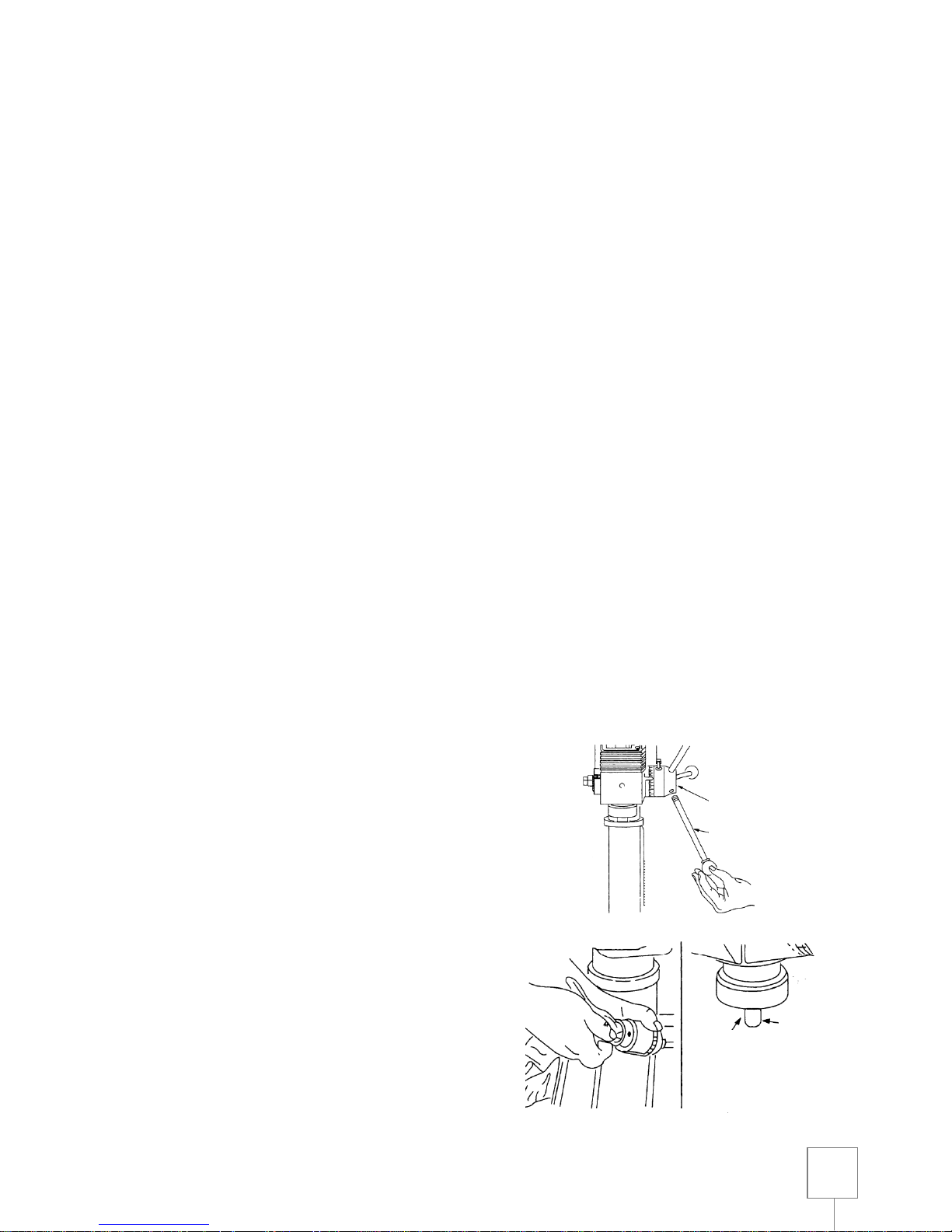
INSTALLING THE TABLE
1. Loosen the support lock and raise the table
support by turning the table crank clockwise until
the support is at a working height level. Tighten
support lock.
2. Remove the protective covering from the table.
Place the table in the table support and tighten the
table lock (located under the table) by hand.
NOTE: If table won’t fit into the table support
easily, try to open the table support with a falt
blade screw driver.
INSTALLING THE HEAD
CAUTION: Head assembly weighs about 25 kg.
Carefully lift head in two people.
1. Remove protective bag from head assembly.
Carefully lift head above column tube and slide it
onto column making sure that the head slides
down over the column as far as possible. Align the
head with the table and the base.
2. Locate two D 10 mm x 12 mm long set screws
(see illustration) in loose parts bag.
3. Install a set screw in each hole (as indicated) on
the right side of the head, and using a 5mm hex
“L” wrench, tighten the two head lock set screws.
Support
lock
Table
support
Column
Table crank
Rack
Table lock
Table
Table
support
Column
Head
Head lock set
screws
Head
Page 13
13
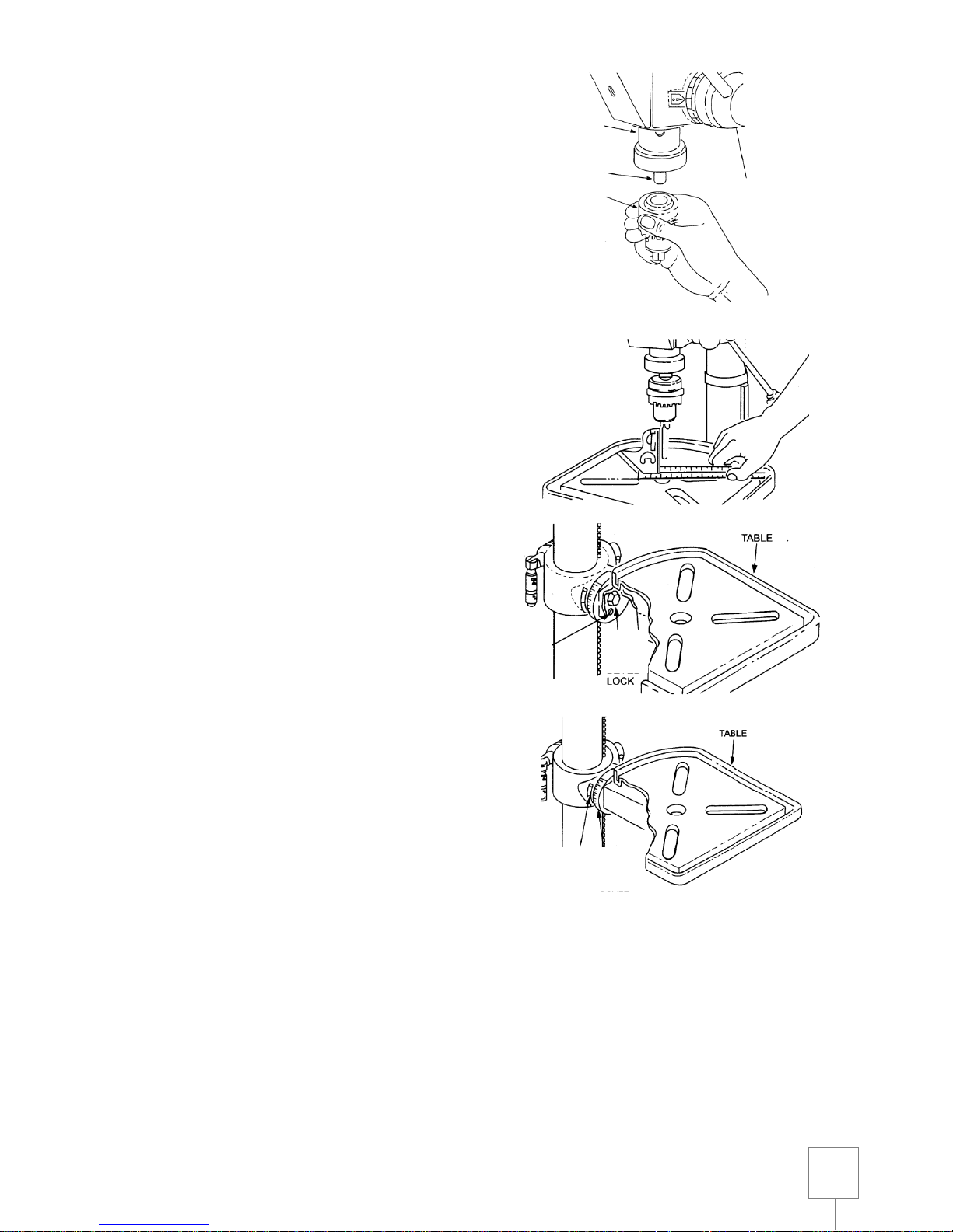
INSTALLING BELT
1. Locate two V-belts in the loose parts bag.
2. Use speed chart inside belt guard to choose
speed for drilling operation. Install belts in correct
position for desired speed. The longer one of the
two belts is always positioned between the spindle
pulley and the idler pulley.
3. Apply tension to the belt by turning belt tension
handle anti-clockwise until belt deflects
approximately 1 cm by thumb pressure at its
centre.
4. Tighten belt tension lock handle.
NOTE: Over tensioning belt could make the motor
not to start or damage bearings.
5. If blet slips while drilling, readjust belt tension.
INSTALLING BELT GUARD KNOB
1. To attach belt guard knob, locate the knob and a
D 5mm x 12mm long pan headed screw in loose
parts bag. Install the screw in the hole located in
the guard and attach the knob by turning it until it
is tight.
CAUTION: To avoid possible injury keep the guard in
place and in proper working order while operating.
INSTALLING FEED HANDLES
1. Locate three feed handles among loose parts.
2. Screw the feed handles into the threaded holes in
the hub and tighten.
INSTALLING THE CHUCK
1. Clean out the tapered hole in the chuck. Clean the
tapered surface on the arbor with a clean cloth.
Make sure there are no foreign particles sticking
to the surfaces. The slightest piece of dirt on any
of these surfaces will prevent the chuck from
seating properly. This will cause the drill to
“wobble”.
2. Slide the chuck up over the arbor as illustrated.
3. Unlock support lock and raise table so ti is about 5
cm below tip of the chuck.
Spindle
pulley
Idler pulley
Belt tension
lock handle
Belt tension
handle
Belt guard
Belt guard knob
Pah headed
screw
Hub
Feed handles
Clean this
surface
Arbor
Page 14
14
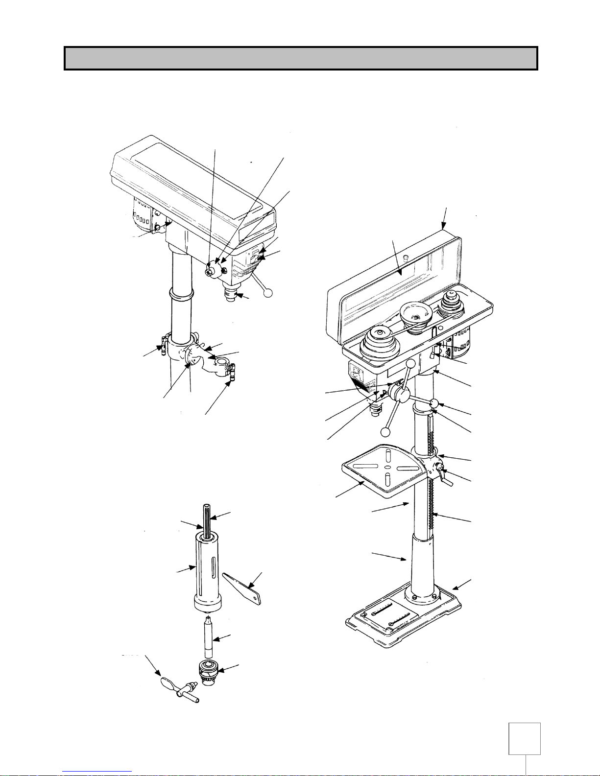
4. Turn the sleeve clockwise and open chuck’s jaws
completely.
5. Turn feed handles anti-clockwise and force chuck
against the table until the chuck is secure.
ADJUSTING THE TABLE SQUARE TO HEAD
NOTE: Use a precise right angle square (not included)
1. Insert a straight ground stell ord or a straight drill
bit (not included) approximately 8 cm long into the
chuck and tighten.
2. With the table raised at a working height and
locked on column, place the combination square
flat on the table beside the rod.
3. If an adjustment is necessary, loosen the set
screw under bevel lock with 24mm flat wrench.
These adjustments are located under the table.
4. Align the table square to the bit by rotating the
table until the square and the bit are in line.
5. Retighten the table bevel lock.
6. Retighten the set screw.
BEVEL SCALE
NOTE: The bevel scale has been included to provide a
quick method for beveling the table to aproximate
angles. If precise accuracy is necessary, a square or
another precision measuring tool should be used to
position the table.
To use the bevel scale proceed as follows:
1. Loosen set screw and table bevel lock (see step 3
above).
2. Move the table so that the desired angle or bevel
scale is straight across from zero line on table
support.
3. Retighten table bevel lock and set screw.
Piano
Piano
Bloccaggio
inclinazione
piano
Vite di
fermo
Puntatore
Scala graduata
Quill
Arbor
Chuck
Table
bevel
lock
Pointer
Scale
Table
Table
Set
screw
Page 15
15
DRILL PRESS DESCRIPTION
25
FEED SPRING
ADJUSTMENT
26
FEED SPRING
17
SPRING CAP
27
DRILL ON-OFF
SWITCH
18
CHUCK
2
BELT TENSION
LOCK HANDLE
23
SUPPORT LOCK
22
BEVEL SCALE
21
TABLE LOCK
19
ARM
20
TABLE BEVEL LOCK
(UNDER THE TABLE)
29
DRILL SPEED TABLE
(INSIDE BELT
GUARD)
1
BELT GUARD
2
BELT TENSION LOCK
HANDLE
3
BELT TENSION HANDLE
4
HEAD LOCKS
5
FEED HANDLE
6
COLUMN COLLAR
7
TABLE SUPPORT
8
TABLE CRANK
9
RACK
10
BASE
SPINDLE GROOVES
RACK (TEETH)
WEDGE KEY
24
CHUCK KEY
18
CHUCK
ARBOR
13
TABLE
11
COLUMN
SUPPORT
12
COLUMN
QUILL AND SPINDLE ASSEMBLY
INSIDE THE DRILL PRESS
16
DEPTH SCALE
LOCK
15
DEPTH SCALE
INDICATOR
14
DEPTH SCALE
Page 16

16
1. BELT GUARD ASSEMBLY – Covers pulleys and belt during operation.
2. BELT TENSION LOCK HANDLE – Tightens motor support and belt tenions handle to maintain
correct belt distance and tension.
3. BELT TENSION HANDLE – Turn handle anti-clockwise to apply tension to the belt, turn it clockwise
to release belt tension.
4. HEAD LOCKS – Lock the head to the column. Always have them locked in place during use.
5. FEED HANDLE – It must be used to move the quill up and down. One or two may be removed if
necessary whenever the workpiece is of such unusual shape that it interferes with the handles.
6. COLUMN COLLAR – Holds the rack to the column. Rack remains movable in collar to permit table
support movements.
7. TABLE SUPPORT – Rides on column to support movements.
8. TABLE CRANK – Turn it clockwise to elevate table. Support lock must be released before using
crank.
9. RACK – Combines with gear mechanism to provide easy elevation of table by hand operated table
crank.
10. BASE – Supports drill press. For additional stability, holes are provided in the base to bolt it to the
floor.
11. COLUMN SUPPORT – Support column, guides rack and provides mounting holes for column to
base.
12. COLUMN – Connects head, table and base on a one piece tube for easy alignement and
movement.
13. TABLE – Provides working surface to support workpiece.
14. DEPTH SCALE – Shows depth of hole being drilled.
15. DEPTH SCALE INDICATOR – Indicates drilling depth selected on depth scale.
16. DEPTH SCALE LOCK – Locks the depth scale to selected depth.
17. SPRING CAP – Provides means to adjust quill spring tension.
18. CHUCK – Holds drill bit or other recommended accessories to perform desired operations.
19. ARM – Extends beyond table support for mounting and alinging the table.
20. TABLE BEVEL LOCK – Locks the table in any position from 0 to 45°.
21. TABLE LOCK – Table can be rotated in various positions and locked.
22. BEVEL SCALE – Shows the degree table is tilted for bevel operations. Scale is mounted on top of
arm.
23. SUPPORT LOCK – Tighten and locks table support to column. Always have it locked in place while
operating with the drill press.
24. CHUCK KEY – It is a self-ejecting chuck key which will pop out of the chuck when you let go of it.
This action has been designedto prevent throwing of the chuck key from the chuck when power is
turned « ON ». Do not use any other key as a substitute, order a new one if damaged or lost.
25. FEED SPRING ADJUSTMENT – Refere to par. « Assembly of the belt ».
26. FEED SPRING – Refere to par. « Assembly of the belt ».
27. DRILL ON-OFF SWITCH – Has locking feature. This feature is intentended to prevent unauthorized
and possible hazardous use by children and others.
29. DRILLING SPEED CHART – Drilling speed can be changed by placing the belt in any of the grooves
in the pulleys. See spindle speed label inside belt guard to approximately determine drilling speed.
Page 17
17
Factors entailing better results with drill presses are the type of material, hole’s size, type of bit or miller
and cutting quality desired. The smaller the bit is, the faster the necessary speed must be. Speed must
be higher when processing soft materials than hard metals. Use the recommended speed for the bit you
are using and for the material to be cut
The chuck of this drill press can turn at 12 different speed levels: from 210 to 2220 RPM. You can obtain
the lowest speed by placing the belt on the smaller step of motor’s pulley and on the biggest of spindle’s
pulley.
The switch is located on the front side of drill press’ head. To start the machine, push the green button “I”
of the switch (ON); to stop it, push the red button “O” of the switch (OFF).
The switch of this tool is an under voltage switch that prevents the drill press from starting automatically
in case of restart of the electric current after an interruption; then when an interruption of the electric
current occurs the drill press stops and to make it restart you have to push the green button again.
1. All ball bearings are packed with grease at the factory. They require no further lubrication.
Periodically lubricate the grooves in the spindle and the rack (head of the quill).
2. Insert the bit into the chuck far enough to obtain maximum grip of chuck jaws. Make sure that the
drill press is centered in the chuck. Tighten the bit sufficiently, so that it doesn’t slip while drilling.
Turn the chuck key clockwise to tighten, and anti-clockwise to loosen the drill bit.
3. Drilling depth may be controlled by using the pointer and the depth scale or by the two stop nuts on
the feed stop rod.
4. to position the table, loosen support lock handle, move the table to the desired position and
retighten support lock. To tilt the table, loosen the bevel lock, tilt the table to the desired position on
the bevel scale and retighten bevel lock.
5. After drilling a hole, release the feed handle to have the spindle sleeve return to its original
position.
CAUTION: Switch off the machine and disconnect it from the power supply by removing the plug from
the socket before any adjustment, repair, maintenance task or when changing the blade.
In case you find out any damage to the protection devices or irregularities while processing or checking
the machine, you must get it repaired immediately by qualified persons.
Before use check that the protection and safety devices are perfectly efficient. After carrying out the
work, make a general cleaning of the machine by removing dust and chips.
Keep the chuck protection perfectly working.
Be sure that the axle of the spindle and the column are sliding by cleaning and oiling them periodically.
Clean the ventilation inlets of the engine.
Periodically check that the supply cable is not damaged.
Periodically check the tensioning of the belt.
DRILLING SPEED
MAINTENANCE
STARTING THE DRILL PRESS
USE
Page 18
18
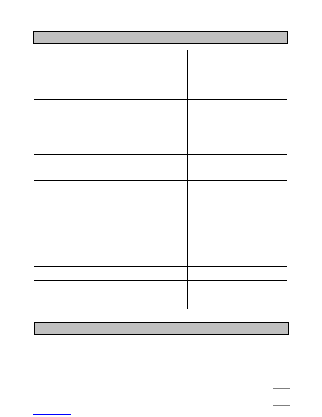
TROUBLE
PROBABLE CAUSE
REMEDY
Noisy operation
. Incorrect belt tension
. Adjust tension
. Dry spindle
. Lubricate spindle
. Loose spindle pulley
. Check tightness of retaining nut on
pulley
. Loose motor pulley
. Tighten set screws in pulleys
Drill bit burns
. Incorrect speed
. Change speed
. Chpis not coming out of hole
. Retract drill bit frequently to clear
chips
. Dull drill bit
. Resharpen drill bit
. Feeding too slow
. Feed fast enough – allow drill bit to cut
. Not lubricated
. Lubricate drill bit with cutting or motor
oil
Hole is not round
. Hard grain in wood or lengths of drill
bit cutting lips and / or angles not
equal
. Resharpen drill bit correctly
. Bent drill bit
. Repalce drill bit
Wood splinters on
underside
. No back up material under
workpiece
. Use back up material
Woodpiece torn loose
from hand
. Not supported or clamped properly
. Support workpiece or clamp it
Drill bit binds in
workpiece
. Workpiece piching drill bit or
excessive fee pressure
. Support workpiece or clamp it
. Improper belt tension
. Adjust tension
Excessive drill bit
. Bent drill bit
. Use a straight drill bit
run out or wobble
. Worn spindle bearings
. Reaplace bearings
. Drill bit not properly installed in
chuck
. Install drill bit properly
. Chuck not properly installed
. Install chuck properly
Quill returns too slow
or too fast
. Spring has improper tension
. Adjust spring tension
Chuck will not stay
attached to spindle. It
falls off when trying to
install it
. Dirty, grease or oil on the tapered
inside surface of chuck or on the
spindles tapered surface
. Using a household detergent, clean
the tapered surfaces of the chuck and
spindle to remove all dirt, grease and
oil
All the tools and accessories are made and checked by using the safest and most modern productive
methods. However, if a tool get damaged, it must be repaired by an authorized after sales centre.
You can sending a request to the e-mail address
TROUBLE SHOOTING
AFTER-SALES SERVICE
Page 19
19
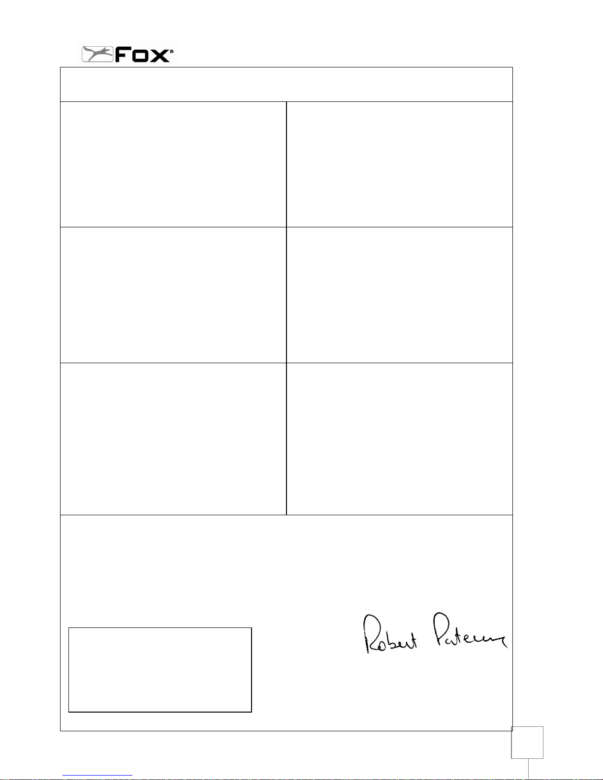
DICHIARAZIONE DI CONFORMITA’
secondo la Direttiva Europea 2006/42/CE Allegato II.A
DART Tool Group
Wheatfiled Road, Dunnikier Business Park
Kirkcaldy, KY1 3PD, Scotland
dichiara che la macchina:
TRAPANO A COLONNA F12-943A
prodotta nel (vedi etichetta riportata):
- è conforme alle disposizioni della Direttiva 2006/42/CE e alle
disposizioni di attuazione;
inoltre è conforme alle seguenti disposizioni e relative attuazioni:
2006/95/CE, 2004/108/CE, 2011/65/UE, 2012/19/UE.
DECLARACIÓN DE CONFORMIDAD
según la Directiva Europea 2006/42/CE Anexo II.A
DART Tool Group
Wheatfiled Road, Dunnikier Business Park
Kirkcaldy, KY1 3PD, Scotland
declara que la máquina:
TALADRO DE COLUMNA F12-943A
fabricada en (ver la etiqueta ilustrada):
- Cumple los requisitos de la norma 2006/42/CE y las
disposiciones de aplicación;
Asimismo, cumple las normas siguientes y sus correspondientes
aplicaciones: 2006/95/CE,2004/108/CE,2011/65/UE,2012/19/UE.
DECLARATION OF CONFORMITY
in compliance with European Directive 2006/42/EC Appendix II.A
DART Tool Group
Wheatfiled Road, Dunnikier Business Park
Kirkcaldy, KY1 3PD, Scotland
declares that the machine
DRILL PRESS F12-943A
manufactured in (see affixed label):
- conforms to the regulations indicated in 2006/42/EC and
relative regulations of implementation;
- furthermore it conforms to the following regulations and
relative implementation:
2006/95/EC, 2004/108/EC, 2011/65/UE,2012/19/UE.
DECLARAÇÃO DE CONFORMIDADE
segundo a Directiva Europeia 2006/42/CE Anexo II.A
DART Tool Group
Wheatfiled Road, Dunnikier Business Park
Kirkcaldy, KY1 3PD, Scotland
declara que a máquina:
BERBEQUIM DE COLUNA F12-943A
produzida em (ver etiqueta indicada):
- está em conformidade com as disposições da
directiva 2006/42/CE e com as disposições de actuação;
- está também em conformidade com as seguintes
disposições e respectivas actuações:
2006/95/CE, 2004/108/CE, 2011/65/UE,2012/19/UE.
DÉCLARATION DE CONFORMITÉ
selon la Directive Européenne 2006/42/CE Annexe II.A
DART Tool Group
Wheatfiled Road, Dunnikier Business Park
Kirkcaldy, KY1 3PD, Scotland
déclare que la machine:
PERCEUSE A COLONNE F12-943A
produite en (voir étiquette reportée):
- est conforme aux dispositions de la 2006/42/CE et aux
dispositions de réalisation;
- en outre elle est conforme aux dispositions suivantes et
relatives réalisations:
2006/95/CE, 2004/108/CE, 2011/65/UE,2012/19/UE
Persona autorizzata a costituire il fascicolo tecnico:
Person authorized to create the technical file:
Pessoa autorizada a constituir o fasciculo técnico:
Persona autorizada a crear el documento técnico:
Personne autorisée à étabilir le dossier technique:
ROBERT PATERSON
DART Tool Group
Wheatfield Road, Dunnikier Business Park, Kirkcaldy, KY1 3PD
Kirkcaldy
01/09/2015
INGOMBRO PER
ETICHETTA
Page 20
20
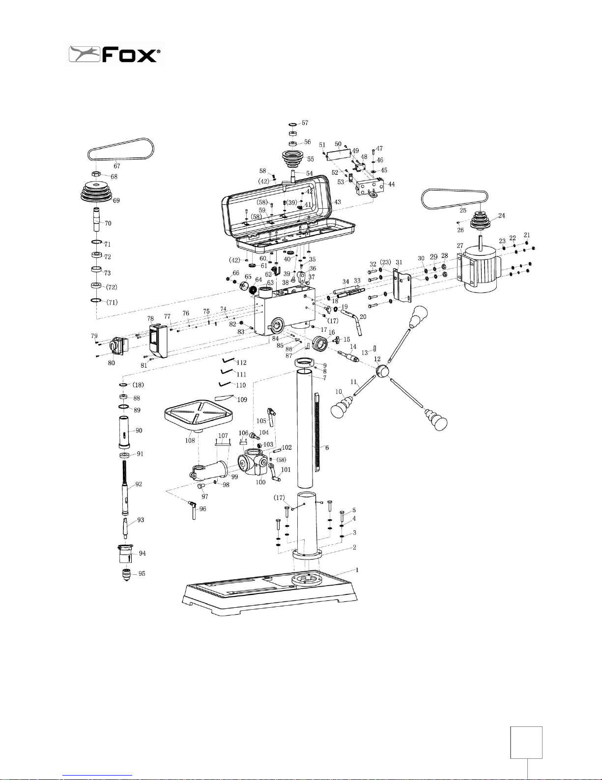
F12-942A
TRAPANO A COLONNA / DRILL PRESS / PERCEUSE A COLONNE
Page 21
21
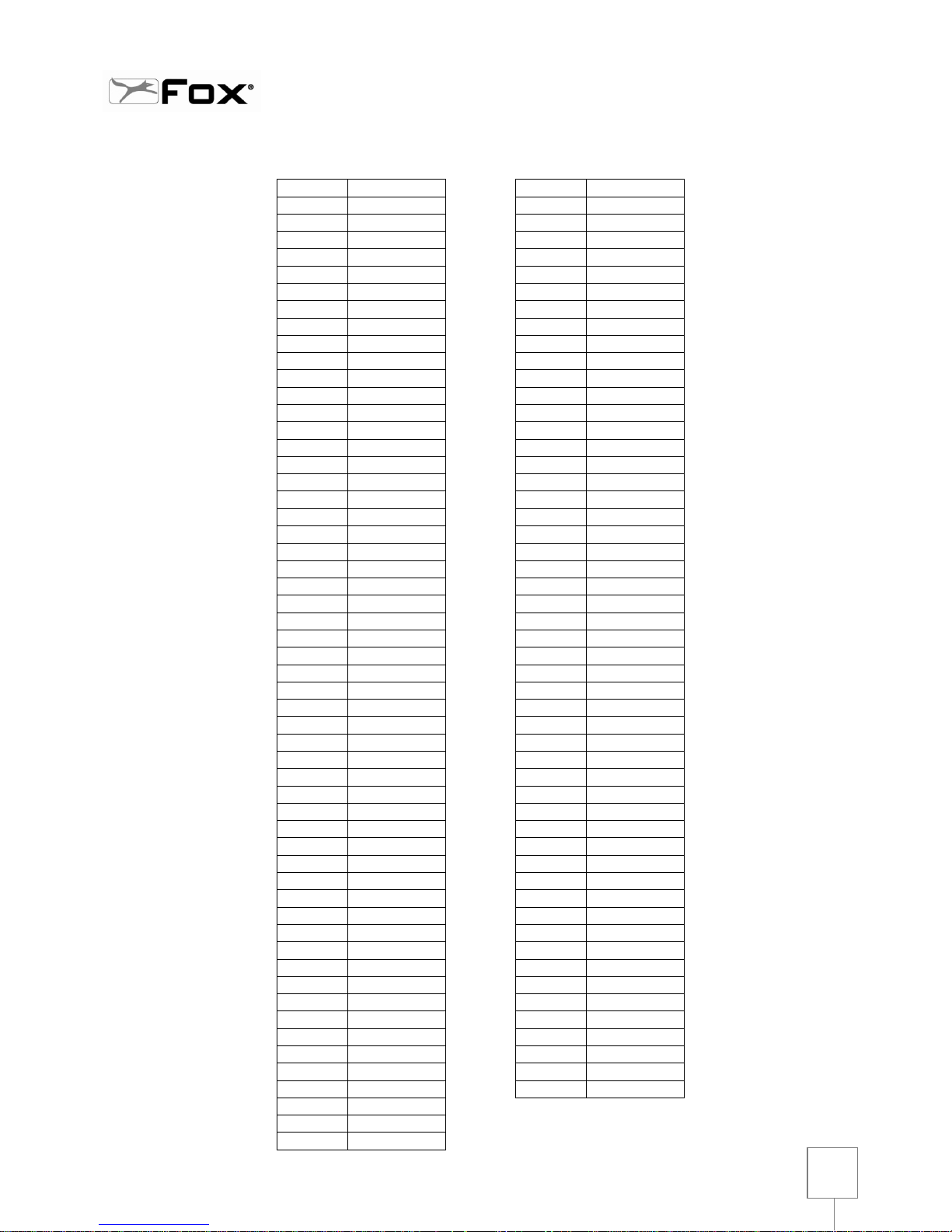
F12-942
TRAPANO A COLONNA / DRILL PRESS / PERCEUSE A COLONNE
N.
Art.
N.
Art.
1
F12942A-001
56
F12942A-056
2
F12942A002
57
F12942A-057
3
F12942A003
58
F12942A-058
4
F12942A004
59
F12942A-059
5
F12942A005
60
F12942A-060
6
F12942A006
61
F12942A-061
7
F12942A007
62
F12942A-062
8
F12942A008
63
F12942A-063
9
F12942A009
64
F12942A-064
10
F12942A010
65
F12942A-065
11
F12942A011
66
F12942A-066
12
F12942A012
67
F12942A-067
13
F12942A-013
68
F12942A-068
14
F12942A-014
69
F12942A-069
15
F12942A-015
70
F12942A-070
16
F12942A-016
71
F12942A-071
17
F12942A-017
72
F12942A-072
18
F12942A-018
73
F12942A-073
19
F12942A-019
74
F12942A-074
20
F12942A-020
75
F12942A-075
21
F12942A-021
76
F12942A-076
22
F12942A-022
77
F12942A-077
23
F12942A-023
78
F12942A-078
24
F12942A-024
79
F12942A-079
25
F12942A-025
80
F12942A-080
26
F12942A-026
81
F12942A-081
27
F12942A-027
82
F12942A-082
28
F12942A-028
83
F12942A-083
29
F12942A-029
84
F12942A-084
30
F12942A-030
85
F12942A-085
31
F12942A-031
86
F12942A-086
32
F12942A-032
87
F12942A-087
33
F12942A-033
88
F12942A-088
34
F12942A-034
89
F12942A-089
35
F12942A-035
90
F12942A-090
36
F12942A-036
91
F12942A-091
37
F12942A-037
92
F12942A-092
38
F12942A-038
93
F12942A-093
39
F12942A-039
94
F12942A-094
40
F12942A-040
95
F12942A-095
41
F12942A-041
96
F12942A-096
42
F12942A-042
97
F12942A-097
43
F12942A-043
98
F12942A-098
44
F12942A-044
99
F12942A-099
45
F12942A-045
100
F12942A-100
46
F12942A-046
101
F12942A-101
47
F12942A-047
102
F12942A-102
48
F12942A-048
49
F12942A-049
50
F12942A-050
51
F12942A-051
52
F12942A-052
53
F12942A-053
54
F12942A-054
55
F12942A-055
Page 22
22
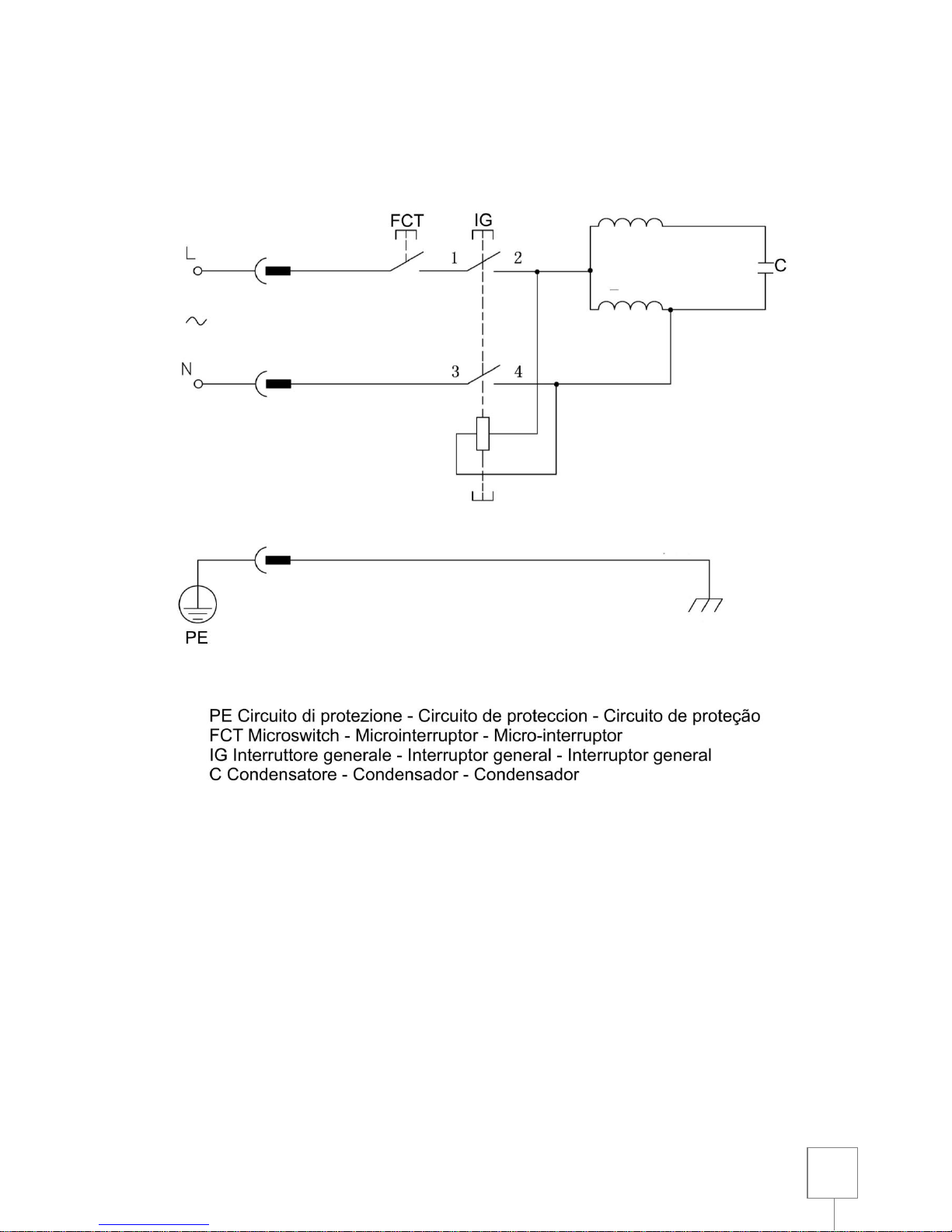
SCHEMA ELETTRICO / WIRING DIAGRAM / SCHEMA ELECTRIQUE
Page 23

23
DART Tool Group
Wheatfield Road, Dunnikier Business Park
Kirkcaldy, KY1 3PD
E-Mail: [email protected] – www.darttoolgroup.com
 Loading...