

Four winns Horizon 200, Horizon 220, Horizon 240, Sundowner 225, Sundowner 245 Owner's Manual
...

PREFACE
This manual will acquaint you with the use and maintenance of your new Four Winns boat. This manual also
provides special information critical to the safety of the passengers, and longevity of the equipment. The
information on the following page lists the conventions used to increase the visibility of these important messages. Also included in your owner’s packet is the “Boating Basics, A Guide to Responsible Boating”. This
publication covers all the boating basics and should be read along with your Four Winns Owners Manual before
operating your boat. Review this information in detail.
Four Winns continually strives to improve its products. Unit specifications, including standard and optional
equipment are constantly being modified. Equipment availability is also subject to change. The most
current and accurate information available at the time of publication is included in this manual. Some
variation in equipment, description, location, and details can result.
The information in this manual focuses upon the equipment designed and manufactured by Four Winns on
specific models. When appropriate, please utilize the information pertinent to your specific boat model.
Equipment such as engines, and other accessories are manufactured by others. The information provided in
this manual is intended to be used in conjunction with the information provided by the manufacturers of this
equipment. All information available at the time of manufacture has been included with your owner’s packet.
Read this entire manual carefully before operating your new boat. Many instructions may require direct
performance of the activity to fully understand the correct method. If you choose to read this manual at home,
remember to take it to the boat with you.
Y our Four Winns dealer knows your boat best and is interested in your complete satisfaction. Return to him for
service or other assistance. If you find it necessary to contact Four Winns directly , please refer to the address
information listed below. Be sure to include the boat model, serial number, your daytime telephone number,
and specifics of the information desired.
This manual has been specifically developed for 1998-current model year 200-240 Horizons and 205-245
Sundowners models. Please record the model and serial number information below.
Model Serial Number
________________________ __________________________
This manual should be considered part of the boat. Should you sell the boat, pass this manual on to the new
owner. Take special care of this manual. Certain information in this manual may not be available in a replacement manual.
Thank you for joining the Four Winns family. We appreciate your purchase and welcome the opportunity to
demonstrate our commitment to you.
Four Winns Customer Service Department
925 Frisbie Street
Cadillac, Michigan 49601
1-800-FOUR WINNS (Dealer Locator) • 231-775-1343 (Switchboard)
231-779-2345 (FAX-Warranty Dept.) • 231-775-3963 (FAX-Parts Dept.)
E-Mail Address: boating@fourwinns.com
© Four Winns L.L.C. 2000. All Right s Reserved.
Owner’s Manual
05/00
Preface
Page 1
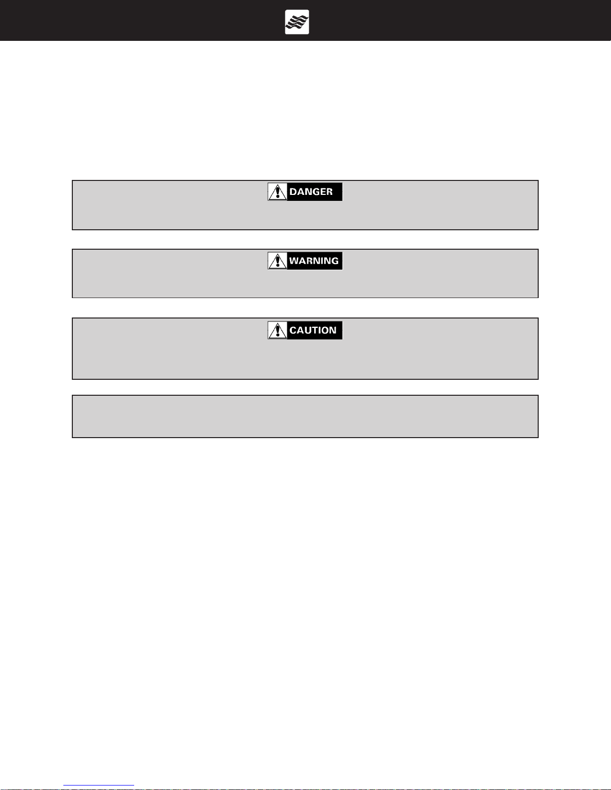
WARNING CONVENTIONS
This manual contains instructions critical to the safety of those aboard or the longevity of the equipment.
Pay close attention to all safety warnings. The conventions below have been adopted to increase the
visibility of this information throughout the manual.
This safety symbol and this signal word indicate an imminently hazardous situation which if not
avoided, WILL result in death or serious injury.
This safety symbol and this signal word indicate a potentially hazardous situation which, if not
avoided CAN result in severe injury or death.
This safety symbol and this signal word indicate a potentially hazardous situation which, if not
avoided MA Y result in minor or moderate personal injury or property damage. It may also be used
to alert against unsafe practices.
NOTICE
This is used to notify people of installation, operation, or maintenance information which is important
but not hazard-related.
YOU are responsible for your own safety , as well as the safety of your passengers and fellow boaters.
Y ou should fully underst and and become familiar with the operating procedures and safety precautions in this manual and any other information in the owner’s packet before you launch the boat.
Always operate your boat with consideration, courtesy , and common sense.
The warnings in this manual do not and can not address every conceivable situation. Always use common
sense!
The following page illustrates the locations of various warning labels, capacity label and other stickers on
your Four Winns boat.
Owner’s Manual
05/00
Preface
Page 2
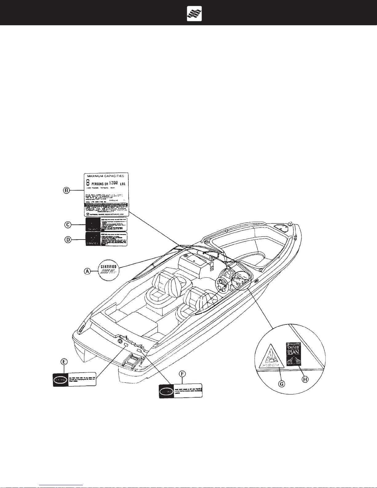
CAP ACITY LABEL AND OTHER STICKER LOCA TIONS
The NMMA cap acity label and various warning stickers are placed at dif ferent locations on each model for
your safety . Additional warnings for fuel leakage, blower operation, and other import ant information will be
imprinted or located on the dash. Many of these stickers and labels are not required by the U.S. Coast
Guard but are important to ensure the safe operation of your Four Winns boat. In addition, the Hull
Identification Number plate is pop-riveted below the deck-hull joint in the starboard aft corner .
Below are letters corresponding to the various locations for each item on the drawings. See pages 4, 5,
and 6 for the actual wording of each of the various warning labels found on your boat.
(A) NMMA Certified (E) Ski T ow Warning
(B) Capacity Label (F) Ladder Warning
(C) Procedure Checklist (G) Armorcote Sticker
(D) Equipment Checklist (H) Winning Edge Sticker
Owner’s Manual
05/00
Figure 1: Horizon Models
Preface
Page 3

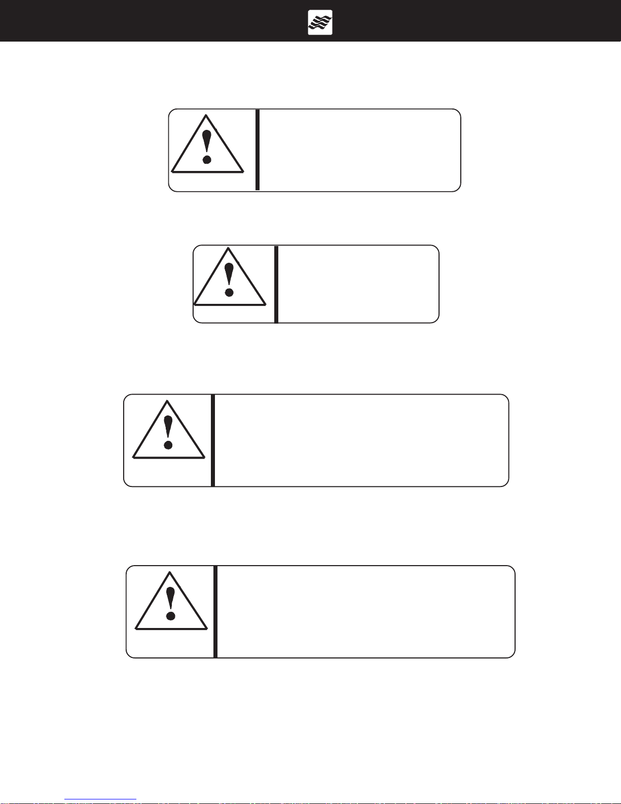
A. NMMA CERTIFICATION STICKER
WARNING
BEFORE ST ARTING ENGINE:
EQUIPMENT
DRAIN PLUG - SECURED?
MOVEABLE SEATS - SECURED?
LIFE JACKET - ONE FOR EACH PERSON?
OTHER EMERGENCY GEAR - ON BOARD?
PROCEDURES
EMERGENCY STOP SWITCH - TETHER
HOOKED UP?
EVERYBODY - SEA TED IN BOAT? NEVER
ON SEATBACKS, RAISED SEATS, OR
EDGES OF BOAT!
OPERAT OR’S VISION - UNOBSTRUCTED?
WEATHER CONDITIONS - SAFE TO GO
OUT?
PASSENGERS - AWARE OF EMERGENCY
PROCEDURES?
C & D. EQUIPMENT AND
PROCEDURES CHECKLIST
B. CAPACITY LABEL
(NOTE: CAP ACITY WILL VARY DEPENDING
UPON WHICH MODEL YOU HAVE.)
DO NOT USE SKI TOW FITTING
FOR LIFTING OR P ARASAILING.
FITTING COULD PULL OUT OF
DECK RESULTING IN SERIOUS
INJURY OR DEATH.
WARNING
E. SKI TOW W ARNING LABEL
SHUT OFF MOTOR WHEN NEAR
SWIMMERS. SEVERE INJURY OR
DEATH WILL RESULT FROM
CONTACT WITH A ROT ATING
PROPELLER.
DANGER
F. BOARDING LADDER WARNING LABEL
G. ARMORCOAT STICKER
Owner’s Manual
05/00
NEVER APPROACH OR USE
LADDER WHEN MOTOR IS
RUNNING. SEVERE INJURY
OR DEA TH WILL RESULT
FROM CONTACT WITH
DANGER
ROT ATING PROPELLER.
F. BOARDING LADDER WARNING LABEL
H. WINNING EDGE STICKER
Preface
Page 4
Additional warnings not shown on page 3.
GASOLINE VAPORS CAN EXPLODE RESULTING
IN INJURY OR DEA TH. BEFORE ST ARTING ENGINE
-CHECK ENGINE BILGE COMPARTMENT FOR
GASOLINE OR VAPORS, AND
-OPERATE BLOWER FOR FOUR MINUTES, AND
VERIFY BLOWER OPERATION.
WARNING
RUN BLOWER WHEN VESSEL IS OPERATING BELOW CRUISING SPEED.
I. POWERED VENTILA TION FOR GAS ENGINES
NO VENTILATION IS PROVIDED.
FUEL VAPORS ARE A FIRE AND
EXPLOSION HAZARD. TO AVOID
INJURY OR DEATH, DO NOT STORE
FUEL OR FLAMMABLE LIQUIDS HERE.
WARNING
J. NO VENTILA TION WARNING LABEL
WARNING
WARNING
CARBON MONOXIDE IS PRODUCED BY ALL
GASOLINE ENGINES AND GENERATOR SETS.
AVOID BRAIN DAMAGE OR DEATH FROM CARBON MONOXIDE.
KEEP COCKPIT AND CABIN AREAS WELL VENTILATED.
AVOID BLOCKAGE OF EXHAUST OUTLETS.
SIGNS IF EXPOSURE INCLUDE NAUSEA, DIZZINESS, AND DROWSINESS.
SEE BOAT OWNER’S MANUAL FOR MORE DETAILS.
IF USING A CATALYTIC HEATER, PROVIDE VENTILATION.
DO NOT USE CATALYTIC HEATER WHILE SLEEPING.
K. CARBON MONOXIDE
EXHAUST FUMES FROM ENGINES CONTAIN CARBON MONOXIDE.
BOATS WITH CANVAS DEPLOYED ARE MORE LIKELY TO COLLECT
EXHAUST FUMES. AVOID BRAIN DAMAGE OR DEATH FROM CARBON
MONOXIDE. KEEP COCKPIT AND CABIN AREAS WELL VENTILATED.
SIGNS OF EXPOSURE INCLUDE NAUSEA, DIZZINESS, AND DROWSINESS.
SEE BOAT OWNER’S MANUAL FOR MORE DETAILS. IF USING A
CATALYTIC HEATER, PROVIDE VENTILATION. DO NOT USE CATALYTIC
HEATER WHILE SLEEPING.
L. CARBON MONOXIDE
Owner’s Manual
05/00
Preface
Page 5
WARNING
AVOID SERIOUS INJURY OR DEATH
FROM FIRE OR EXPLOSION RESULTING
FROM LEAKING FUEL. INSPECT SYSTEM
FOR LEAKS A T LEAST ONCE A YEAR.
WARNING
M. LEAKING FUEL WARNING LABEL
TO MINIMIZE SHOCK AND FIRE HAZARDS:
(1) TURNOFF THE BOAT’S SHORE CONNECTION SWITCH BEFORE
CONNECTING OR DISCONNECTING SHORE CABLE.
(2) CONNECT SHORE POWER CABLE AT THE BOAT FIRST.
(3) IF POLARITY WARNING INDICA T OR IS ACTIV A TED, IMMEDIA TEL Y
DISCONNECT CABLE.
(4) DISCONNECT SHORE POWER CABLE AT SHORE OUTLET FIRST.
(5) CLOSE SHORE POWER INLET COVER TIGHTLY.
N. SHORE POWER WARNING
Owner’s Manual
05/00
Preface
Page 6
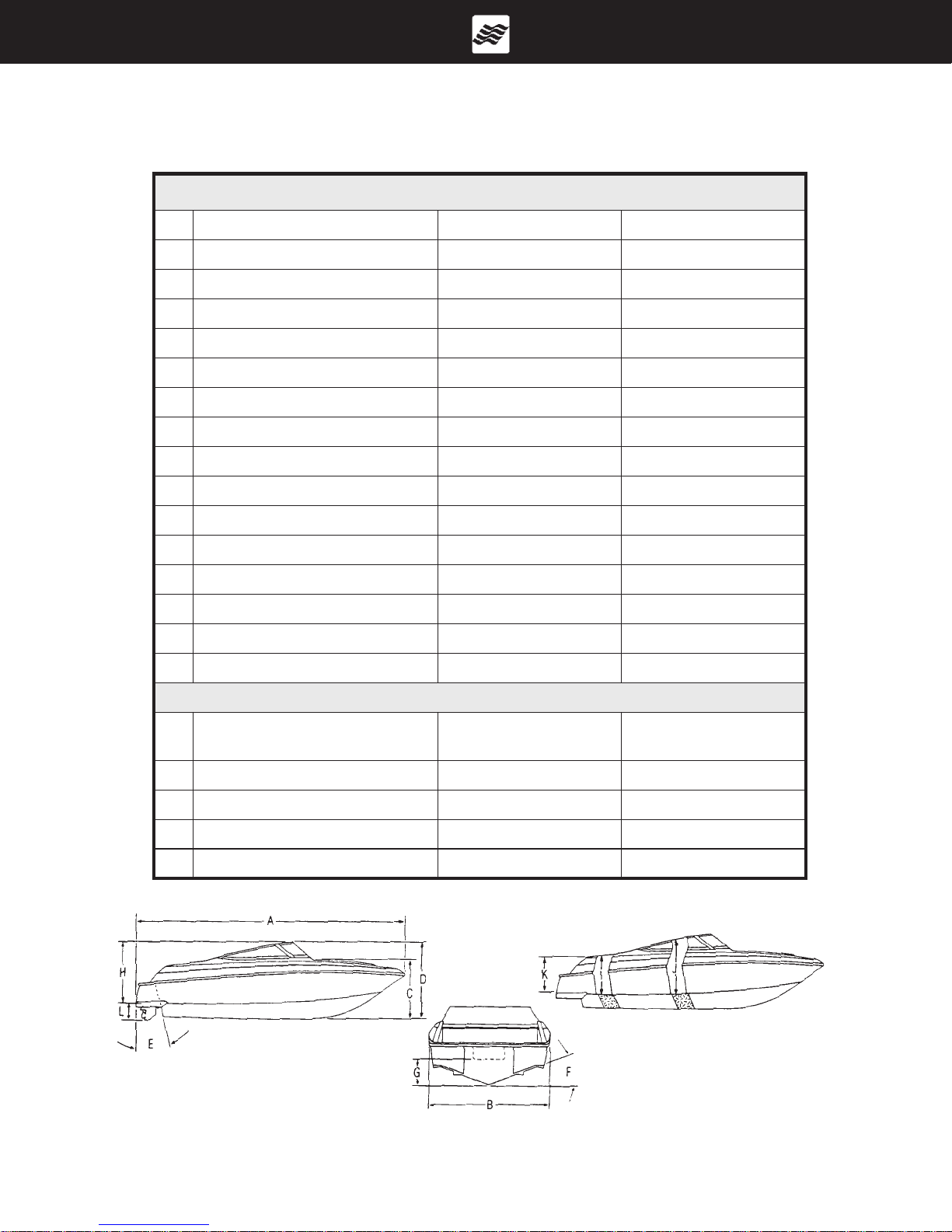
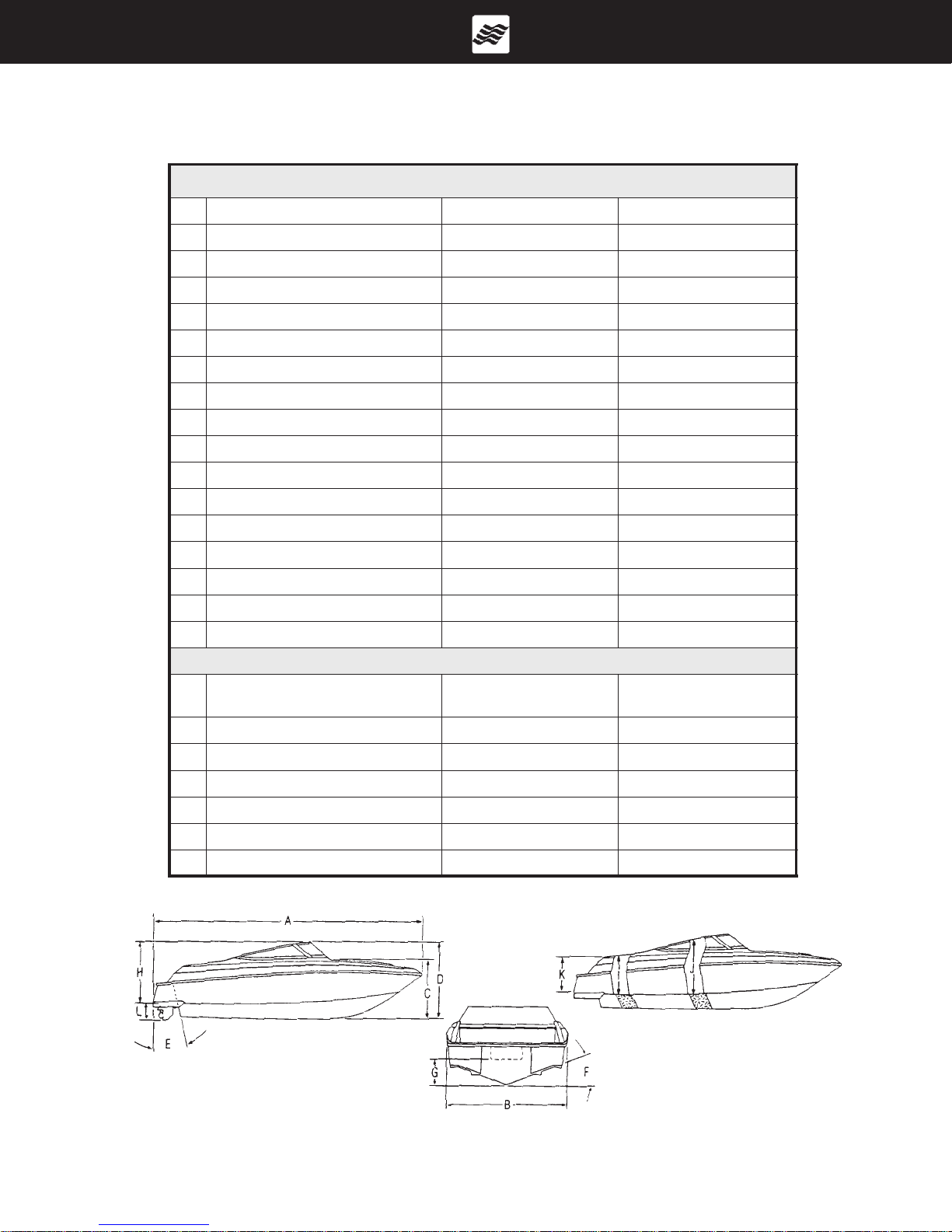
BOW RIDER SPECIFICATIONS
NOZIROH002
:SNOITACIFICEPSSUCIRTEM
A:AOL
B:maeB
C:flehSdleihsdniWotleeK
"2'02m21.6
"1'8m44.2
"25m23.1
D:thgieHlatoT"36m6.1
E:elgnAmosnarT51
F:esirdaeD91
o
o
H:ecnaraelCegdirB"1'4m42.1
I:)nretS(thgieHtipkcoC"92mc47
J:)mleH(thgieHtipkcoC"13mc97
K:)niM(draobeerF"92mc47
L:)nwoDevirD(tfarD"23mc18
L:)pUevirD(tfarD"51mc83
:leuFlag53l331
:sregnessaP0101
:yticapaCmumixaMsbl0061gk037
STHGIEW&SGNITARREWOP
epyTenignE
XS/LG0.5461022
XS/iG0.5781052
XS/iSG7.5902082
rewoPtfahsporP
WKPH
SBL
GK
0692
0431
0792
0531
0792
0531
thgieWreliarTSBL)T(0001-)S(008GK)T(054-)S(063
o
51
o
91
enignE&taoB
sthgieW
A. LOA
B. BEAM
C. KEEL TO W/S SHELF
D. TOTAL HEIGHT
E. TRANSOM ANGLE
F. DEAD RISE
Owner’s Manual
05/00
G. OB TRANSOM HEIGHT - NA
H. BRIDGE CLEARANCE
I. COCKPIT STERN HEIGHT
J. COCKPIT HEIGHT HELM
K. FREEBOARD
L. DRAFT
Preface
Page 7

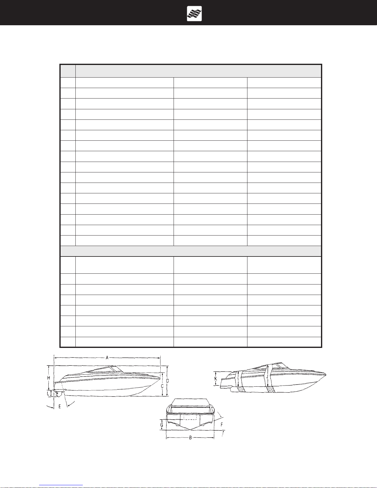
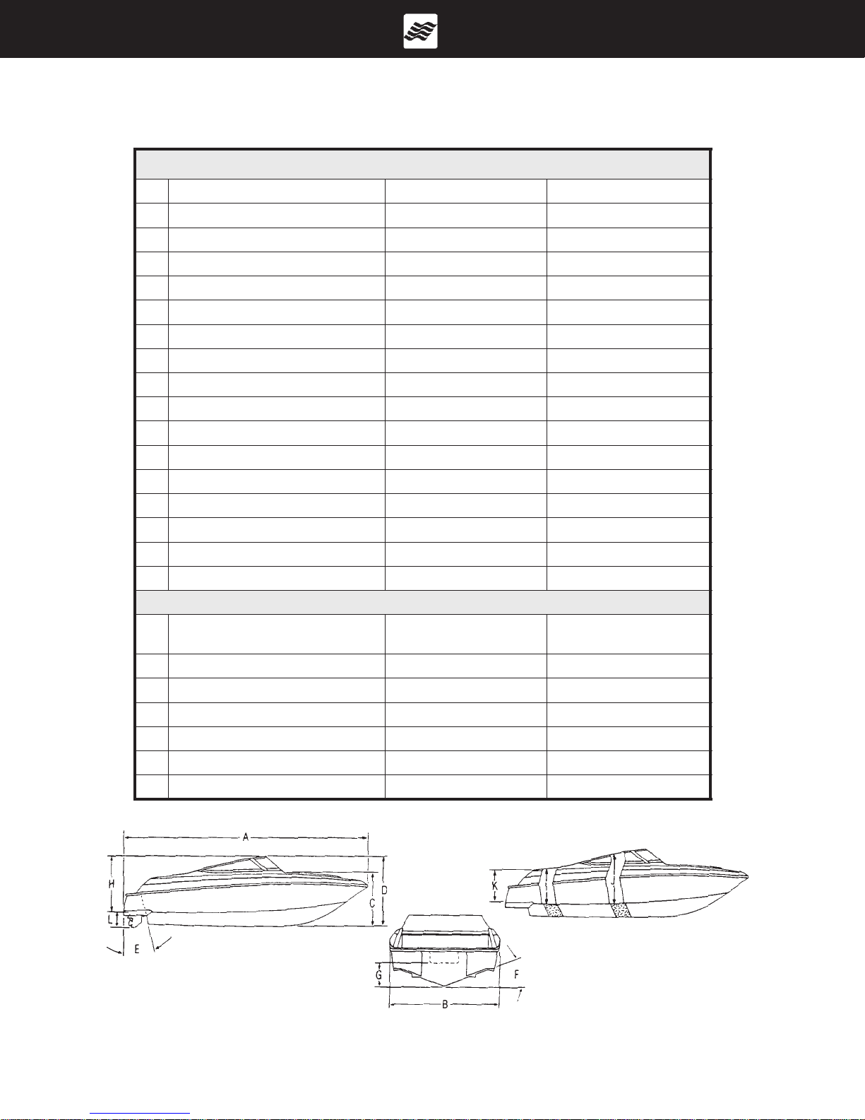
BOW RIDER SPECIFICATIONS
NOZIROH022
:SNOITACIFICEPSSUCIRTEM
A:AOL
B:maeB
C:flehSdleihsdniWotleeK
"9'12m36.6
"4'8m45.2
"85m74.1
D:thgieHlatoT"07m87.1
E:elgnAmosnarT41
F:esirdaeD02
o
o
H:ecnaraelCegdirB"7'4m04.1
I:)nretS(thgieHtipkcoC"13mc87
J:)mleH(thgieHtipkcoC"63mc19
K:)niM(draobeerF"33mc38
L:)nwoDevirD(tfarD"53mc98
L:)pUevirD(tfarD"81mc54
:leuFlag05l091
:sregnessaP2121
:yticapaCmumixaMsbl0591gk488
STHGIEW&SGNITARREWOP
epyTenignE
XS/iG0.5781052
XS/iSG7.5902082
/iSG7.5 *porpouD 902082
XS/iG4.7132013
/iG4.7 *porpouD 132013
rewoPtfahsporP
WKPH
SBL
GK
0723
0841
0723
0841
0923
0941
0743
0751
0943
0851
)mednaT(thgieWreliarTSBL4501GK474
o
41
o
02
enignE&taoB
sthgieW
A. LOA
B. BEAM
C. KEEL TO W/S SHELF
D. TOTAL HEIGHT
E. TRANSOM ANGLE
F. DEAD RISE
Owner’s Manual
05/00
.srelleporpleetssselniatssedulcniporpouD*
G. OB TRANSOM HEIGHT - NA
H. BRIDGE CLEARANCE
I. COCKPIT STERN HEIGHT
J. COCKPIT HEIGHT HELM
K. FREEBOARD
L. DRAFT
Preface
Page 8
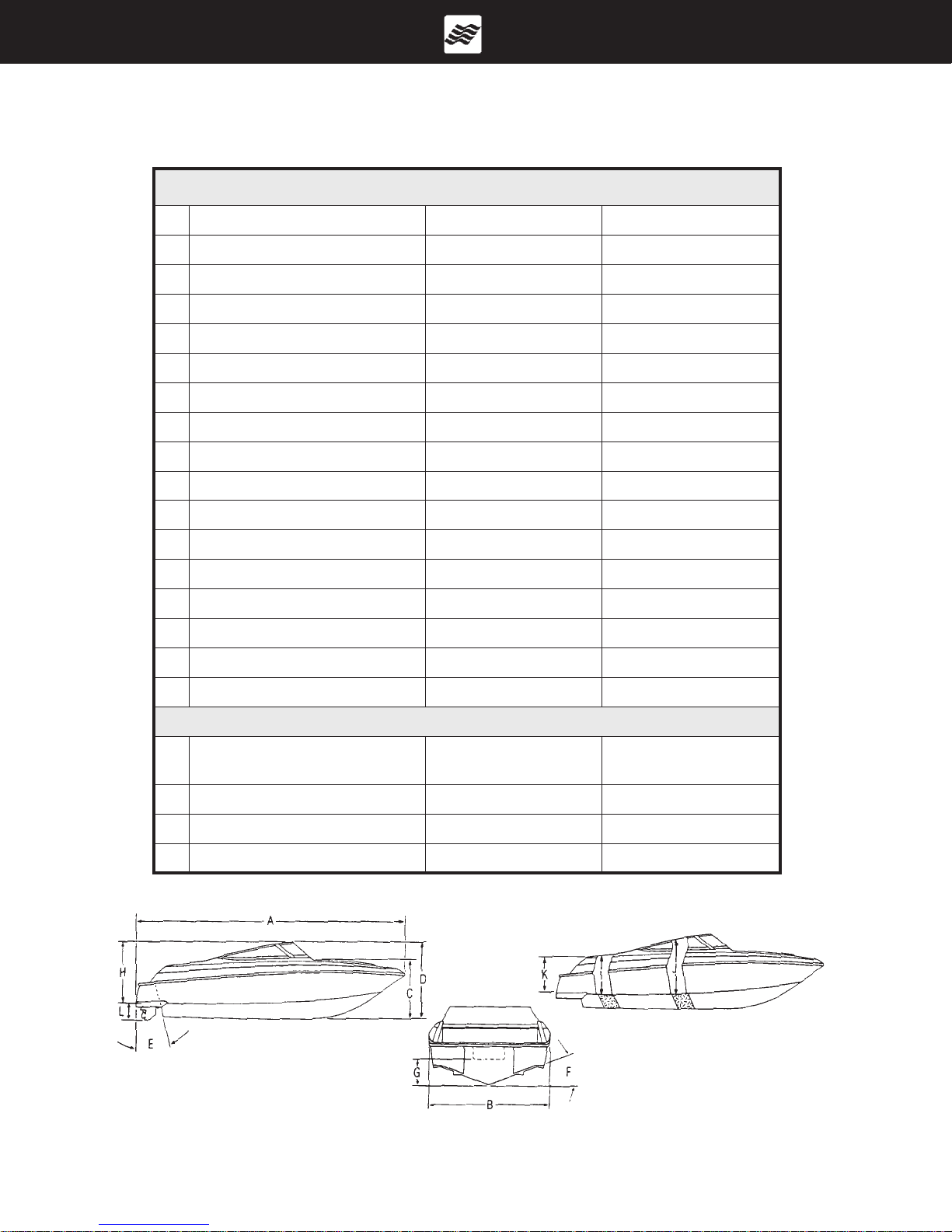
BOW RIDER SPECIFICATIONS
NOZIROH042
:SNOITACIFICEPSSUCIRTEM
A:AOL
B:maeB
C:flehSdleihsdniWotleeK
"2'42m73.7
"6'8m95.2
"16m55.1
D:thgieHlatoT"47m88.1
E:elgnAmosnarT51
F:esirdaeD02
o
o
H:ecnaraelCegdirB'5m25.1
I:)nretS(thgieHtipkcoC"13mc97
J:)mleH(thgieHtipkcoC"73mc49
K:)niM(draobeerF"63mc09
L:)nwoDevirD(tfarD"53mc98
L:)pUevirD(tfarD"81mc54
:leuFlag56l642
:sregnessaP3131
:yticapaCmumixaMsbl0052gk4311
STHGIEW&SGNITARREWOP
epyTenignE
XS/SG7.5781052
XS/iSG7.5902082
/iSG7.5 *porpouD 902082
XS/iG4.7132013
/iG4.7 *porpouD 132013
rewoPtfahsporP
WKPH
SBL
GK
0383
5371
0483
0471
0683
0571
0404
0381
0604
0481
/iSG4.7 *porpouD ?583??
o
51
o
02
enignE&taoB
sthgieW
A. LOA
B. BEAM
C. KEEL TO W/S SHELF
D. TOTAL HEIGHT
E. TRANSOM ANGLE
F. DEAD RISE
Owner’s Manual
05/00
)mednaT(thgieWreliarTSBL0811GK135
.srelleporpleetssselniatssedulcniporpouD*
G. OB TRANSOM HEIGHT - NA
H. BRIDGE CLEARANCE
I. COCKPIT STERN HEIGHT
J. COCKPIT HEIGHT HELM
K. FREEBOARD
L. DRAFT
Preface
Page 9
CUDDY SPECIFICATIONS
RENWODNUS502
:SNOITACIFICEPSSUCIRTEM
A:AOL
B:maeB
C:flehSdleihsdniWotleeK
"6'02m52.6
"1'8m64.2
"85m74.1
D:thgieHlatoT"07m87.1
E:elgnAmosnarT51
F:esirdaeD91
o
o
H:ecnaraelCegdirB"9'4m54.1
**thgieHnibaC"2'4m72.1
I:)nretS(thgieHtipkcoC"23mc18
J:)mleH(thgieHtipkcoC"53mc98
K:)niM(draobeerF"23mc18
L:)nwoDevirD(tfarD"03mc67
L:)pUevirD(tfarD"31mc33
:leuFlag53l531
:sregnessaP99
:yticapaCmumixaMsbl0051gk086
o
51
o
91
Owner’s Manual
05/00
epyTenignE
XS/LG0.5461022
XS/iG0.5781052
)mednaT(thgieWreliarTSBL)T(0001-)S(008GK)T(054-)S(063
nwohStoN**
A. LOA
B. BEAM
C. KEEL TO W/S SHELF
D. TOTAL HEIGHT
E. TRANSOM ANGLE
F. DEAD RISE
STHGIEW&SGNITARREWOP
rewoPtfahsporP
WKPH
SBL
GK
0023
0541
0123
enignE&taoB
sthgieW
0641
G. OB TRANSOM HEIGHT - NA
H. BRIDGE CLEARANCE
I. COCKPIT STERN HEIGHT
J. COCKPIT HEIGHT HELM
K. FREEBOARD
L. DRAFT
Preface
Page 10
CUDDY SPECIFICATIONS
RENWODNUS522
:SNOITACIFICEPSSUCIRTEM
A:AOL
B:maeB
C:flehSdleihsdniWotleeK
"9'12m36.6
"4'8m45.2
"85m74.1
D:thgieHlatoT"37m58.1
E:elgnAmosnarT41
F:esirdaeD02
o
o
H:ecnaraelCegdirB"11'4m05.1
**thgieHnibaC"4'4m23.1
I:)nretS(thgieHtipkcoC"92mc47
J:)mleH(thgieHtipkcoC"83mc79
K:)niM(draobeerF"83mc79
L:)nwoDevirD(tfarD"53mc98
L:)pUevirD(tfarD"81mc54
:leuFlag05l091
:sregnessaP1111
:yticapaCmumixaMsbl0091gk268
STHGIEW&SGNITARREWOP
epyTenignE
XS/LG0.5461022
XS/iG0.5781052
/iG0.5 *porpouD 781052
XS/iSG7.5902082
/iSG7.5 *porpouD 902082
rewoPtfahsporP
WKPH
SBL
GK
0943
0851
0053
0951
0253
0061
0943
0851
0053
0951
)mednaT(thgieWreliarTSBL4501GK474
.srelleporpleetssselniatssedulcniporpouD*
nwohStoN**
o
41
o
02
enignE&taoB
sthgieW
A. LOA
B. BEAM
C. KEEL TO W/S SHELF
D. TOT AL HEIGHT
E. TRANSOM ANGLE
F. DEAD RISE
Owner’s Manual
05/00
G. OB TRANSOM HEIGHT - NA
H. BRIDGE CLEARANCE
I. COCKPIT STERN HEIGHT
J. COCKPIT HEIGHT HELM
K. FREEBOARD
L. DRAFT
Preface
Page 11
CUDDY SPECIFICATIONS
RENWODNUS542
:SNOITACIFICEPSSUCIRTEM
A:AOL
B:maeB
C:flehSdleihsdniWotleeK
"2'42m73.7
"6'8m95.2
"96m36.1
D:thgieHlatoT"28m30.2
E:elgnAmosnarT51
F:esirdaeD02
o
o
H:ecnaraelCegdirB"6'5m86.1
**thgieHnibaC"7'4m04.1
I:)nretS(thgieHtipkcoC"33mc48
J:)mleH(thgieHtipkcoC"73mc49
K:)niM(draobeerF"33mc48
L:)nwoDevirD(tfarD"73mc49
L:)pUevirD(tfarD"02mc05
:leuFlag56l642
:sregnessaP2121
:yticapaCmumixaMsbl0052gk4311
STHGIEW&SGNITARREWOP
epyTenignE
XS/SG7.5781052
/SG7.5 *porpouD 781052
XS/iSG7.5902082
/iSG7.5 *porpouD 902082
/iG4.7 *porpouD 132013
rewoPtfahsporP
WKPH
SBL
GK
0714
0981
0914
0091
0714
0981
0914
0091
0044
0002
)mednaT(thgieWreliarTSBL0811GK135
.srelleporpleetssselniatssedulcniporpouD*
nwohStoN**
o
51
o
02
enignE&taoB
sthgieW
A. LOA
B. BEAM
C. KEEL TO W/S SHELF
D. TOTAL HEIGHT
E. TRANSOM ANGLE
F. DEAD RISE
Owner’s Manual
05/00
G. OB TRANSOM HEIGHT - NA
H. BRIDGE CLEARANCE
I. COCKPIT STERN HEIGHT
J. COCKPIT HEIGHT HELM
K. FREEBOARD
L. DRAFT
Preface
Page 12

TABLE OF CONTENTS
WARRANTY AND SERVICE ..................................................................................................................... 1
A - 1 FOUR WINNS WARRANTY POLICY .................................................................................... 1
A - 2 HULL STRUCTURE WARRANTY ......................................................................................... 1
A - 3 WARRANTY REGISTRATION ............................................................................................... 1
A - 4 TRANSFER OF WARRANTY ................................................................................................ 1
A - 5 PRE-OWNED UNIT REGISTRATION.................................................................................... 1
A - 6 INSURANCE COVERAGE .................................................................................................... 2
A - 7 SERIAL NUMBER RECORD ................................................................................................. 2
A - 8 PRE-DELIVERY SERVICE .................................................................................................... 2
A - 9 REPLACEMENT PARTS ....................................................................................................... 2
A - 10 WINNGEAR
ENGINES AND INSTRUMENTATION ....................................................................................................... 1
B - 1 GENERAL ............................................................................................................................. 1
B - 2 ENGINE EXHAUST ............................................................................................................... 1
B - 3 ENGINES .............................................................................................................................. 2
B - 4 PROPELLERS ....................................................................................................................... 2
A. Diameter ......................................................................................................................... 2
B. Pitch ................................................................................................................................ 2
C. Prop Slip ......................................................................................................................... 2
B - 5 RUNNING ANGLE & POWER TRIM/TILT .............................................................................. 3
A. Power Trim...................................................................................................................... 3
B. Power Tilt ........................................................................................................................ 3
B - 6 TRIM TABS ........................................................................................................................... 4
A. Control Listing ................................................................................................................. 4
B. Induce Planing & Control Trim Angle .............................................................................. 5
C. Trim Tab Maintenance .................................................................................................... 5
B - 7 ENGINE INSTRUMENTATION .............................................................................................. 5
A. Tachometer ..................................................................................................................... 6
B. Speedometer................................................................................................................... 6
C. Temperature Gauge ........................................................................................................ 6
D. Oil Pressure Gauge ......................................................................................................... 6
E. Voltmeter ......................................................................................................................... 7
F. Fuel Gauge ..................................................................................................................... 7
G. Power Trim Gauge .......................................................................................................... 7
H. Depth Sounder ................................................................................................................ 7
I. Ignition Switch ............................................................................................................... 10
J. Emergency Ignition Shut-Off .......................................................................................... 10
K. Engine Hour Meter ......................................................................................................... 11
L. Alarm Systems ............................................................................................................... 11
M. Instrument Maintenance ................................................................................................. 11
N. 2000 VDO Quick Start Card ............................................................................................ 12
Ô
..........................................................................................................................................................................................................................................
2
Owners Manual
05/00
Table of Contents
Page 1

CONTROL SYSTEMS .............................................................................................................................. 1
C - 1 GENERAL ............................................................................................................................. 1
C - 2 CONTROL OPERATION ....................................................................................................... 1
A. Carbureted Engines ......................................................................................................... 1
B. Fuel Injected Engines (EFI) ............................................................................................... 2
C - 3 NEUTRAL SAFETY SWITCH ................................................................................................ 2
C - 4 CONTROL SYSTEM MAINTENANCE ................................................................................... 2
STEERING SYSTEMS ............................................................................................................................. 1
D - 1 GENERAL ............................................................................................................................. 1
A. Rotary Steering ................................................................................................................ 1
B. Tilt Steering ..................................................................................................................... 1
C. Power Steering ................................................................................................................ 1
D - 2 PROPELLER TORQUE ......................................................................................................... 2
D - 3 STEERING SYSTEM MAINTENANCE .................................................................................. 2
A. General Maintenance ...................................................................................................... 2
B. Rotary System Maintenance ............................................................................................ 2
C. Winter Storage ................................................................................................................ 3
ELECTRICAL SYSTEMS ......................................................................................................................... 1
E - 1 GENERAL ............................................................................................................................. 1
E - 2 BATTERY SYSTEM ............................................................................................................... 1
A. Single Battery System ..................................................................................................... 1
B. Dual Battery System ......................................................................................................... 1
C. Battery Switch Operation .................................................................................................. 2
E - 3 12 VOLT ELECTRICAL EQUIPMENT .................................................................................... 3
A. Helm Equipment.............................................................................................................. 3
B. Installation of Additional 12 Volt Equipment ...................................................................... 4
C. Interior Equipment ........................................................................................................... 4
E - 4 ELECTRICAL SYSTEM MAINTENANCE............................................................................... 4
A. Battery Maintenance ........................................................................................................ 4
B. Electrical Wiring Maintenance.......................................................................................... 4
E - 5 STRAY CURRENT CORROSION .......................................................................................... 5
A. General ........................................................................................................................... 5
B. Galvanic Corrosion ........................................................................................................... 5
C. Corrosion Prevention ....................................................................................................... 6
FUEL SYSTEMS ...................................................................................................................................... 1
F - 1 GASOLINE FUEL SYSTEMS ................................................................................................. 1
A. System Testing ................................................................................................................ 1
B. Fuel Fills.......................................................................................................................... 1
C. Anti-Syphon Valves .......................................................................................................... 2
D. Fuel Gauge ..................................................................................................................... 2
E. Fuel Senders ................................................................................................................... 2
F. Fuel Filters ...................................................................................................................... 3
G. Use and Maintenance ...................................................................................................... 3
F - 2 FUEL STANDARDS ............................................................................................................... 3
A. Problems With Alcohol in Gasoline .................................................................................. 4
B. Recommendations .......................................................................................................... 4
F - 3 FUELING INSTRUCTIONS ................................................................................................... 4
Owners Manual
05/00
Table of Contents
Page 2

WASTE & WATER SYSTEMS ................................................................................................................. 1
G - 1 GENERAL ............................................................................................................................. 1
G - 2 DISINFECTING THE WATER SYSTEM ................................................................................ 1
G - 3 FRESH WATER SYSTEMS ................................................................................................... 2
A. Cockpit Galley or Sink...................................................................................................... 2
B. Transom Washdown ......................................................................................................... 2
G - 4 HEADS .................................................................................................................................... 3
A. 205 and 225 Sundowner Portable Heads .......................................................................... 3
B. 240 Horizon Enclosed Head ............................................................................................. 3
C. 245 Sundowner Soft Head.............................................................................................. 3
D. 245 Sundowner Enclosed Head ........................................................................................ 3
E. Pump Out Option .............................................................................................................. 4
G - 5 SYSTEM MAINTENANCE ...................................................................................................... 4
A. Clean Vents and Screens ................................................................................................. 4
B. Winterizing the Water System........................................................................................... 4
VENTILATION AND DRAINAGE SYSTEMS ............................................................................................. 1
H - 1 ENGINE COMPARTMENT VENTILATION ............................................................................. 1
A. Gravity Ventilation System ............................................................................................... 1
B. Forced Air Ventilation ....................................................................................................... 1
C. Engine Ventilation System Maintenance .......................................................................... 1
H - 2 CABIN VENTILATION ............................................................................................................. 1
H - 3 HULL DRAINAGE SYSTEMS ................................................................................................ 2
A. Transom Drain ................................................................................................................ 2
B. Bilge Pumps .................................................................................................................... 2
C. Liner Drains ..................................................................................................................... 2
D. Bilge Compartment Drainage........................................................................................... 2
H - 4 CARBON MONOXIDE ........................................................................................................... 2
A. Definition of Carbon Monoxide ......................................................................................... 3
B. Properties and Characteristics of Carbon Monoxide ......................................................... 3
C. What Makes Carbon Monoxide ....................................................................................... 3
D. How a Person is Affected by Carbon Monoxide ................................................................ 3
E. Effects of Carbon Monoxide ............................................................................................. 3
F. Symptoms ....................................................................................................................... 4
G. Treatment (Evacuate, Ventilate, Investigate, Take Corrective Action) ................................ 4
H. Inspection ........................................................................................................................ 4
I. Operation ........................................................................................................................ 4
J. Boathouses, Sea Walls and Other Boats ......................................................................... 4
K. Backdrafting (Station Wagon Effect) ................................................................................ 5
L. Cabin Appliances ............................................................................................................. 6
M. Ventilation of Accommodation Spaces ............................................................................. 6
N. Altitude and Sea Conditions ............................................................................................. 6
O. Portable Generator Sets .................................................................................................. 6
P. Maintenance - Engine Performance ................................................................................. 6
Q. Maintenance - External Conditions .................................................................................. 7
R. CO Detection Systems .................................................................................................... 7
Owners Manual
05/00
Table of Contents
Page 3

INTERIOR EQUIPMENT .......................................................................................................................... 1
I - 1 ALCOHOL STOVE .................................................................................................................. 1
I - 2 GLOVE BOX ......................................................................................................................... 1
I - 3 IN-DASH COOLER ................................................................................................................ 1
I - 4 STEREO ............................................................................................................................... 1
I - 5 CHERRY HELM ENHANCEMENTS ..................................................................................... 2
I - 6 ANCHOR STORAGE ............................................................................................................ 2
I - 7 SKI STORAGE LOCKER ...................................................................................................... 2
I - 8 HINGED BOW STORAGE .................................................................................................... 2
I - 9 BOW FILL-IN CUSHIONS..................................................................................................... 2
I - 10 AFT FILL-IN CUSHIONS ....................................................................................................... 2
I - 11 WALK-THRU DOOR OPTION (HORIZONS) ........................................................................ 2
I - 12 FENDER STORAGE (HORIZONS) ....................................................................................... 2
SAFETY AND SAFETY EQUIPMENT ...................................................................................................... 1
J - 1 RAILS & DECK HARDWARE ................................................................................................ 1
A. Rails ................................................................................................................................ 1
B. Cleats.............................................................................................................................. 1
C. Transom Ski Tow Ring ..................................................................................................... 1
D. Anchor Locker ................................................................................................................. 1
E. Maintenance.................................................................................................................... 1
J - 2 WINDSHIELDS ..................................................................................................................... 2
J - 3 SWIM PLATFORM ................................................................................................................ 2
J - 4 ANCHOR ............................................................................................................................... 2
J - 5 DEPTH SOUNDER ............................................................................................................... 2
J - 6 SAFETY EQUIPMENT .......................................................................................................... 3
A. Required Safety Equipment ............................................................................................. 3
B. Personal Floatation Devices (PFDs) .............................................................................. 3
C. PFD Types ...................................................................................................................... 3
D. PFD Pointers .................................................................................................................. 4
E. Fire Extinguishers ........................................................................................................... 4
F. Visual Distress Signal Devices ........................................................................................ 5
G. Sound Signaling Devices ................................................................................................ 5
H. Navigation Lights ............................................................................................................ 5
I. Additional Recommended Equipment ............................................................................. 5
J - 7 SAFE BOATING PRACTICES .............................................................................................. 6
A. Drugs and Alcohol ............................................................................................................ 6
B. Safe Operation ................................................................................................................. 6
C. Passenger Safety ............................................................................................................ 6
D. Propeller .......................................................................................................................... 6
E. First Aid ............................................................................................................................ 7
F. Operation By Minors ......................................................................................................... 7
G. Rules of the Road .......................................................................................................... 7
H. Voluntary Inspections ....................................................................................................... 7
I. Safe Boating Courses ....................................................................................................... 7
J - 8 BASIC SEAMANSHIP ........................................................................................................... 7
A. Boating Regulations ......................................................................................................... 7
B. Rules of Seamanship....................................................................................................... 8
J - 9 NAVIGATIONAL AIDS ........................................................................................................... 9
A. International Association of Lighthouse Authorities System B (IALA-B)............................ 9
B. Lateral Markers .............................................................................................................. 10
Owners Manual
05/00
Table of Contents
Page 4

C. Safe Water Markers....................................................................................................... 10
D. The Uniform State Waterway Marking System............................................................... 10
E. A Special Sign ................................................................................................................ 11
F. Noise .............................................................................................................................. 11
J - 10 RECOMMENDED READING ............................................................................................... 11
J - 11 CONTACTS ......................................................................................................................... 11
J - 12 OWNERS LOGS AND RECORDS ..................................................................................... 12
J - 13 NAVIGATIONAL AIDS CHART ............................................................................................ 12
J - 14 WATER SPORTS ................................................................................................................ 13
A. Water Sport Guidelines ................................................................................................... 13
B. Water Skiing ................................................................................................................... 14
UPHOLSTERY ........................................................................................................................................... 1
K - 1 INTERIOR SEATING (SUNDOWNERS) ............................................................................... 1
A. Cabin Tables ..................................................................................................................... 1
B. V-berth Filler Cushions...................................................................................................... 1
K - 2 EXTERIOR SEATING ............................................................................................................. 1
A. Cockpit Tables .................................................................................................................. 1
B. Bow Seating .................................................................................................................... 1
C. Aft Fill-In Seating ............................................................................................................... 1
D. Loungers ......................................................................................................................... 1
E. Bucket Seats ................................................................................................................... 2
F. Stern (Jump) Seats .......................................................................................................... 3
G. Top Storage .................................................................................................................... 4
H. Sunsport Interior .............................................................................................................. 4
K - 3 EXTERIOR UPHOLSTERY CARE ......................................................................................... 4
K - 4 REPLACEMENT UPHOLSTERY ........................................................................................... 5
K - 5 CARPET CARE ..................................................................................................................... 5
A. Interior and Exterior Carpet .............................................................................................. 5
B. Cleaning and Maintenance .............................................................................................. 5
C. Stain Removal ................................................................................................................. 6
D. Stain Removal Procedures .............................................................................................. 6
WEATHER COVERS ................................................................................................................................ 1
L - 1 GENERAL INFORMATION .................................................................................................... 1
A. Convertible Top (Suntop) ................................................................................................. 1
B. Side Curtains................................................................................................................... 2
C. Aft Curtain ....................................................................................................................... 2
D. Forward Cover ................................................................................................................ 2
E. Bimini Top ....................................................................................................................... 2
F. Bimini Camper .................................................................................................................. 3
G. Cockpit Cover.................................................................................................................. 3
H. Mooring Cover................................................................................................................. 3
L - 2 TRAILERING ......................................................................................................................... 4
L - 3 WINTER STORAGE .............................................................................................................. 4
L - 4 MAINTENANCE .................................................................................................................... 4
L - 5 CARBON MONOXIDE ........................................................................................................... 5
FIBERGLASS AND HULL INFORMATION............................................................................................... 1
Owners Manual
05/00
Table of Contents
Page 5

M - 1 HULL DESIGN INFORMATION ............................................................................................. 1
M - 2 FIBERGLASS CONSTRUCTION ........................................................................................... 1
M - 3 EQUIPMENT INSTALLATION ................................................................................................ 1
M - 4 FIBERGLASS CARE & MAINTENANCE ................................................................................ 2
A. General Maintenance ...................................................................................................... 2
B. Weathering Effects on Gel Coat....................................................................................... 2
C. Stains .............................................................................................................................. 3
M - 5 FIBERGLASS REPAIRS ........................................................................................................ 3
A. Scratches ........................................................................................................................ 4
B. Gouges & Cracks ............................................................................................................ 4
C. Osmotic Blistering ........................................................................................................... 5
M - 6 ANTI-FOULING PAINT .......................................................................................................... 5
M - 7 HULL SUPPORT ................................................................................................................... 5
WOODWORK AND COMPOSITES .......................................................................................................... 1
N - 1 HIGH-PRESSURE LAMINATE CARE .................................................................................... 1
N - 2 STAR BOARD ....................................................................................................................... 1
N - 3 CHERRY ENHANCEMENTS ................................................................................................ 1
GENERAL MAINTENANCE ..................................................................................................................... 1
O - 1 WINTERIZATION .................................................................................................................. 1
A. Prior to Lifting for Winter Lay-up ....................................................................................... 1
B. After Lifting ...................................................................................................................... 1
C. Prior to Winter Storage .................................................................................................... 2
O - 2 ENGINE FLUSH OUT ............................................................................................................ 2
O - 3 GENERAL MAINTENANCE SCHEDULE ............................................................................... 3
TRAILERS ................................................................................................................................................ 1
P - 1 GENERAL TRAILER INFORMATION .................................................................................... 1
A. Regulations ...................................................................................................................... 1
B. Load Carrying Capacity .................................................................................................... 1
C. Hitches ............................................................................................................................. 2
P - 2 TRAILER COMPONENTS ...................................................................................................... 2
A. Bunk Supports.................................................................................................................. 2
B. Tongue ............................................................................................................................. 2
C. Swivel Jack ...................................................................................................................... 3
D. Coupling Assembly ........................................................................................................... 4
E. Surge Disc Brakes ........................................................................................................... 4
F. Winch ............................................................................................................................... 5
G. Wheels ............................................................................................................................. 6
H. Spare Tire Carrier ............................................................................................................ 6
I. Lights .............................................................................................................................. 7
J. Tie-downs ........................................................................................................................ 7
P - 3 OPERATION ......................................................................................................................... 8
A. Hitching Trailers ............................................................................................................... 8
B. Backing Up With Surge Disc Brakes ................................................................................ 9
P - 4 TRAILERING ....................................................................................................................... 10
A. Checklist ....................................................................................................................... 10
B. Tactics ........................................................................................................................... 10
P - 5 MAINTENANCE ................................................................................................................... 11
A. Care of Exterior Finish ................................................................................................... 11
Owners Manual
05/00
Table of Contents
Page 6

B. Bunks ............................................................................................................................. 11
C. Swivel Jack .................................................................................................................... 11
D. Brake Actuator & Coupling Assembly .............................................................................. 11
E. Winch ............................................................................................................................. 11
F. Lights ............................................................................................................................. 11
G. Tie-downs ...................................................................................................................... 12
H. Wheels ........................................................................................................................... 12
I. Brakes ........................................................................................................................... 12
J. Bearings ......................................................................................................................... 12
P - 6 AXLE INSPECTION & REPAIRS .......................................................................................... 12
A. Removal of Hub ............................................................................................................. 13
B. Bearing/Seal Inspection and Replacement ...................................................................... 13
C. Hub Reinstallation .......................................................................................................... 13
OPERATION............................................................................................................................................. 1
Q - 1 GENERAL ............................................................................................................................. 1
Q - 2 COMPONENT SYSTEMS ..................................................................................................... 1
Q - 3 SAFETY EQUIPMENT .......................................................................................................... 1
Q - 4 PASSENGER SAFETY .......................................................................................................... 1
Q - 5 RULES OF THE ROAD ....................................................................................................... 1
Q - 6 LIGHTNING ........................................................................................................................... 1
Q - 7 DRINKING AND DRIVING ..................................................................................................... 2
Q - 8 PRE-CRUISE SYSTEM CHECK ............................................................................................ 2
A. Before Starting The Engines ............................................................................................ 2
B. After Starting The Engine ................................................................................................. 2
Q - 9 ENGINE OPERATIONAL PROCEDURES ............................................................................. 2
A. Before Starting ................................................................................................................. 2
B. Cold Engine Start (Carbureted Models) ........................................................................... 3
C. Cold Engine Start (Fuel Injected Engines - EFI) .............................................................. 3
D. Warm Engine Starting...................................................................................................... 3
E. Shifting and Control Speed ............................................................................................. 4
F. Stopping Engine .............................................................................................................. 4
Q - 10 GROUNDING AND TOWING ................................................................................................ 4
Q - 11 BOATING EDUCATION ......................................................................................................... 5
A. Boating Courses .............................................................................................................. 5
B. Boating Manuals or Literature .......................................................................................... 5
C. Charts and Maps ............................................................................................................. 5
GLOSSARY ......................................................................................................................................... 1
FLOAT PLAN ........................................................................................................................................... 1
FUEL LOG ............................................................................................................................................... 1
SERVICE LOG ......................................................................................................................................... 1
SERVICE INFORMATION ........................................................................................................................ 1
ELECTRICAL SCHEMATICS ................................................................................................................... 1
Owners Manual
05/00
Table of Contents
Page 7

W ARRANTY AND SERVICE
A - 1 FOUR WINNS WARRANTY POLICY
The Four Winns Winning Edge Owner Protection Plan,
provides the new Four Winns purchaser with one of the
most comprehensive corporate commitments in the marine industry today. The Four Winns Owner Protection
Plan, defines the warranty coverage on all units manufactured by Four Winns. It thoroughly describes the warranty policies and those procedures to be followed to
obtain warranty coverage. Review the Four Winns Owner
Protection Plan and limited warranty statements carefully .
All engines utilized in the Four Winns product are warranted by the engine manufacturer. Your Four Winns
dealer is authorized to repair your engines and will work
closely with the manufacturer to resolve any problems
you have.
A - 2 HULL STRUCTURE WARRANTY
Each unit manufactured by Four Winns is encompassed
by a separate warranty providing specific coverage on
the hull structure. The Four Winns Owner Protection
Plan thoroughly describes this coverage.
A - 3 WARRANTY REGISTRA TION
A Four Winns W arranty Registration Card is attached to
the Four Winns Owner Protection Plan statement. Y our
Four Winns Dealer is responsible for completing and
mailing the warranty card at the time of purchase. This
is the sole basis for establishing proof of ownership of
the boat and trailer and corresponding warranty validation. Registration of the boat and engines with the manufacturer is required by the Federal Boat Safety Act of
1971.
Other equipment manufacturers also require that their
products be registered with the respective companies.
The warranty registration card is provided in the owner’s
information packet.
A - 4 TRANSFER OF WARRANTY
Four Winns confidence in the product and our warranty
commitments can extend after the original purchaser may
choose to move on to a new boat. Four Winns Warranty coverage is transferable to successive owners of
the boat. Registration of the second or successive owners is required. The Four Winns Owner Protection Plan
thoroughly describes the action required to transfer warranty coverage.
A - 5 PRE-OWNED UNIT REGISTRATION
Section A-4 Transfer of W arranty discussed the need to
properly register the purchase of a pre-owned boat with
Four Winns to transfer applicable warranty coverage.
Purchasers of all Pre-Owned Four Winns models are
encouraged to register ownership with Four Winns. To
register ownership of a “Pre-Owned Four Winns boat,”
provide Four Winns with your name, address, daytime
phone number, purchase date, and hull serial number
of the boat purchased.
If you wish to transfer the warranty , it must be done
so within thirty (30) days of purchase or the warranty will be void. The amount of the transfer fee is
$50.00. Y ou can send the check to Four Winns and we
will notify the engine manufacturer , Volvo Penta, of the
engine warranty transfer. Please include the previous
owner’s “embossed” card with your check. Your new
“embossed” card will be sent to you.
NOTICE
The hull serial number plate is pop-riveted into
the starboard side of the transom. The trailer
serial number is imprinted on an identification
plate affixed to the trailer frame. Please include
these when transferring the warranty .
Registration of a Pre-Owned Four Winns boat does not
extend or in any way affect or modify the specific terms
of the Four Winns Owner Protection Plan or Limited Warranties.
Owner’s Manual
05/00
Section A
Page 1

We provide this service to the purchasers of Pre-Owned
Four Winns boats in the interest of better boating. Four
Winns welcomes every purchaser of a Four Winns boat,
new or used, to our family .
A - 6 INSURANCE COVERAGE
the Pre-Delivery Inspection Form upon accepting delivery of the boat. Y ou are to retain the two copies marked
“Boat Owner”. Y our dealer is to retain the copy marked
“Dealer copy” for his records. The Manufacturer’s copy
is to be mailed to the Four Winns Customer Service
Department.
One of your responsibilities as a new boat owner is to
acquire proper insurance protection. Insurance should
include comprehensive and general liability coverage appropriate to your financial needs. Please contact your
local agent for assistance on insurance coverage.
A - 7 SERIAL NUMBER RECORD
The manufacturer, model, and serial number of major
components are recorded during the assembly of each
Four Winns boat. Two copies of this completed form
are included at the end of this section. One copy should
be removed and kept by the dealer in his records. This
can assist the dealer in processing warranty claims, or
obtaining necessary information. The second copy
should be kept in this owners manual.
A - 8 PRE-DELIVERY SERVICE
Four Winns makes every effort to deliver your boat in
‘turn key’ condition to the dealer. The process of transporting and handling the boat necessitates certain inspections and adjustments prior to delivery to you. Also, various aspects of operation must be checked and adjusted
immediately prior to final delivery and use.
The selling Four Winns dealer must perform this thorough review of the boat and its numerous systems during the commissioning or “dealer pre-delivery service”
of the craft.
A - 9 REPLACEMENT P ARTS
Four Winns dealers are equipped with a Four Winns
Parts Manual that details the components of each model
and their appropriate part numbers. Many Four Winns
dealers inventory common replacement components.
In addition, Four Winns maintains specific records on
the components used in the manufacture of each unit
and makes a concerted effort to maintain components
specifically to fill replacement part needs.
The Four Winns dealer from whom you purchased your
boat is in the best position to meet your needs. If he
does not have the needed item, he has the capability,
through direct contact with the Four Winns Customer
Service Department, to obtain it quickly . Four Winns will
only sell replacement parts to established Four Winns
dealers. If you relocate and cannot find a Four Winns
dealer close to you, contact the Four Winns Customer
Service Department for information on the nearest dealer
in your area.
A - 10 WINNGEAR
Show your colors! Four Winns offers a complete line of
sports clothing designed to complement your new boat.
Y our Four Winns dealer has a complete catalog and pricing, or you can call 1-800-438-2388. Y ou can also check
out our clothing line on our Four Winns’ web site at
www.fourwinns.com.
A Four Winns Pre-Delivery Inspection Form is part of
the Warranty Registration Card. It lists the many items
encompassed by the pre-delivery service previously described. The dealer is to check off the items as they are
completed, and complete the form as indicated providing specific performance related information appropriately .
Y our Four Winns dealer will sign the Pre-Delivery Inspection Form of the Warranty Registration Card upon
completion of the work. You will also be asked to sign
Owner’s Manual
05/00
Section A
Page 2
ENGINES AND INSTRUMENTATION
B- 1 GENERAL
DO NOT attempt to service any engine without
being totally familiar with the safe and proper
service procedures. Do not attempt to maintain or adjust an engine while it is running.
Certain moving parts are exposed and failing
to shut off the engine can result in serious injury or death.
FourWinns does not manufacture engines. Because
of the technical nature of the engines, all manufacturers
of these items require that warranty and service problems be taken directly to an authorized dealer for resolution. The FourWinns dealer from whom you purchased your boat will handle all warranty and service
matters with the engine manufacturer for you.
In compliance with the Federal Boat Safety Act of 1971,
all engine manufacturers require their products to be
registered. A registration card is furnished with each
new engine. When selling a FourWinns boat, the dealer,
along with the purchaser, should complete the information requested on these cards and return them to the
respective engine manufacturers. Engine registration
cards are provided with the engine and will usually be
found with the owners information packet.
Each manufacturer of the various marine power components provides an owners information manual with
their product. This publication is included with this
manual. It is important that you read the manual(s) carefully and become completely familiar with proper care
and operation of the engine system. Be sure to read the
section on winterization. Replacement costs associated
with frozen engine components are quite substantial.
B - 2 ENGINE EXHAUST
The carbon monoxide in exhaust fumes can be hazardous. It is important for you and your passengers to be
aware of the potential safety hazard created by exhaust
fumes. Familiarize yourself with the symptoms of individuals overcome by carbon monoxide, and most importantly, ways you can protect yourself and your guests.
DO NOT inhale exhaust fumes! Exhaust contains carbon monoxide which is colorless and
odorless. Carbon monoxide is a dangerous gas
that is potentially lethal.
Persons overcome by carbon monoxide may
exhibit the following symptoms:
a. Watering and itchy eyes
b. Flushed appearance
c. Throbbing temples
d. Inattentiveness
e. Inability to think coherently
f. Ringing in the ears
g. Tightness across the chest
h. Headache
i. Drowsiness
j. Incoherence
k. Nausea
l. Dizziness
m. Fatigue
n. Vomiting
o. Collapse
p. Convulsions
IF YOU THINK EXHAUST FUMES ARE ENTERING
YOUR BOAT, DETERMINE THE CAUSE AND HAVE
IT CORRECTED IMMEDIATELY!
Also review the other sections in this manual, especially
Sections F on Fuel Systems, and Section C on Control
Systems.
Owners Manual
05/00
The following suggestions can help prevent exhaust
fumes from entering the boat:
1. DO NOT allow the boat to remain stationary with
the engine running for an extended period of time.
Section B
Page 1
2. Use extreme caution while operating the engine in
confined areas such as enclosed slips or congested
piers. Operation under such conditions could easily
lead to exhaust gasses (carbon monoxide) entering
even though you may have all the hatches, windows,
doors and portholes closed.
3. Persons sleeping can be easily overcome by carbon monoxide because they are unaware of its presence. Sleeping while the engine is running is not
recommended. If persons are sleeping aboard while
underway, those awake should monitor for carbon
monoxide accumulation in the cabin; especially the
sleeping areas.
NEVER operate the propulsion engine while
everyone on-board is sleeping. Fatal carbon
monoxide poisoning can occur.
For additional information, refer to Section H-4 Carbon
Monoxide.
B - 3 ENGINES
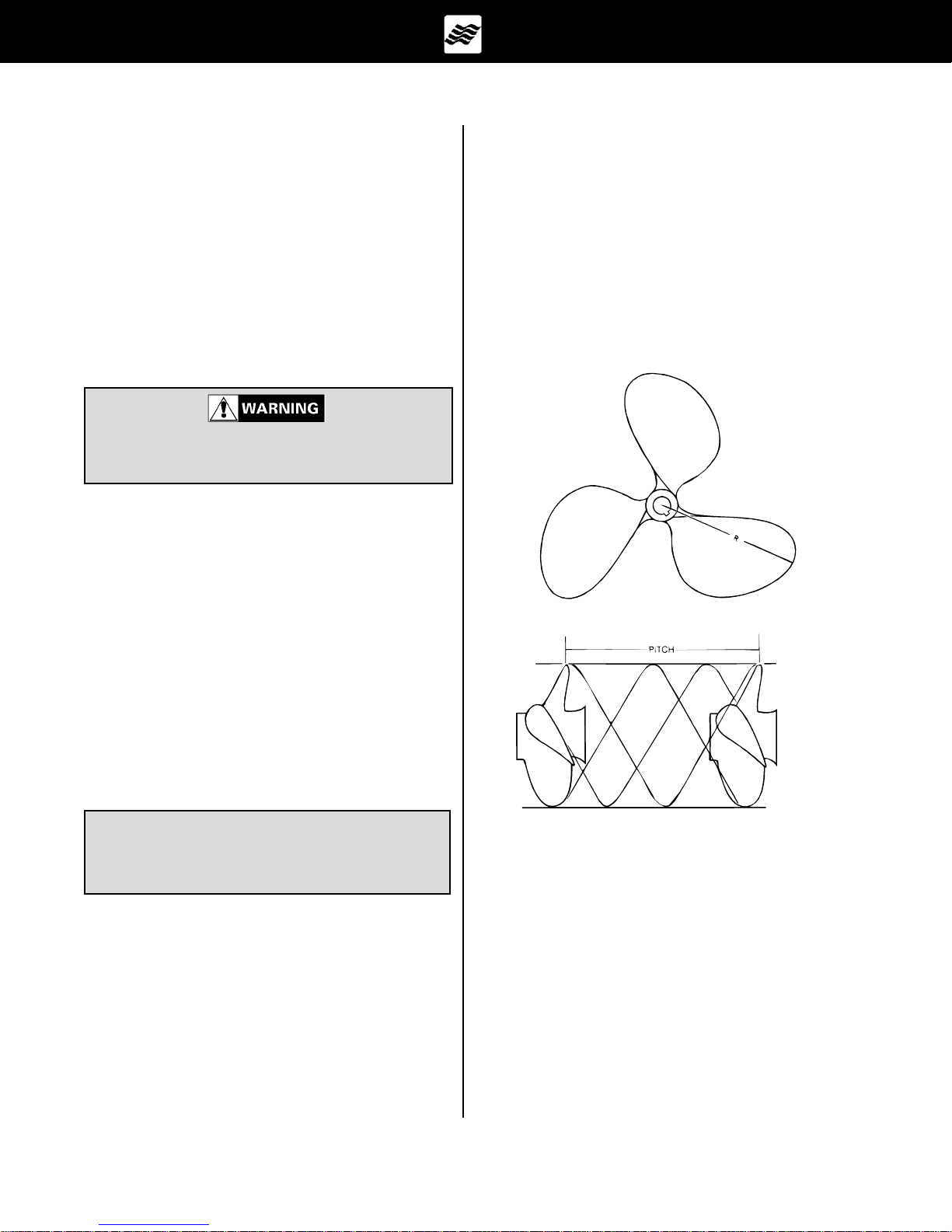
B. Pitch
Pitch is a measure of helix angle, or angle of attack, of
the rotating blade. Pitch is easily understood if one imagines the propeller rotating through a semisolid such as
butter or jello. The distance the propeller will travel in
one revolution is called Pitch. Increasing or decreasing pitch will also have a direct bearing on engine RPMs
because of the greater bite taken by the blade with each
rotation. See Figure B1.
Consult the Engine Owners Manual included in the
owners packet for additional operation and maintenance
information.
B - 4 PROPELLERS
Knowledge of the propeller is most easily gained through
better understanding of the terminology used to refer to
the aspects of propeller size and performance.
NOTICE
Never run with a damaged propeller. You can
damage the engine or drive unit. Keep a spare
propeller on board.
A. Diameter
Diameter is twice the distance from the center of the
prop shaft to the extreme tip of a propeller blade. Increasing or decreasing propeller size will have a direct
bearing on the RPMs an engine will develop. This is
due to the greater amount of propeller blade surface in
contact with the water. See Figure B1.
Figure B1: Propeller Pitch & Diameter
C. Prop Slip
When traveling through water a propeller is unable to
get a complete bite because of the fluidity of water. Prop
Slip is usually expressed as a percent of the computed
theoretical speed. Fifteen to twenty-five percent prop
slip is common for a sport-type boat operating at cruising speed.
Owners Manual
05/00
Section B
Page 2
Changing either diameter or pitch will have an effect on
engine speed and prop slip, and in turn, directly affect
the performance of a boat. The propeller(s) included
with each FourWinns boat provide the best general performance based on data obtained from on-the-water testing of that model. Variations in load, operating conditions, environment, the individual engine and hull performance may necessitate the purchase and use of another propeller(s).
It allows the drive or outboard motor to be raised for
shallow water operation. Power trim also allows the operator to adjust the motor while underway to provide the
ideal running angle for a given load and water condition.
Additional information can be found in the engine
operators manual included in the owners packet.
Under your normal load conditions the engine(s) should
turn within the maximum RPM range when at full throttle.
If the engine(s) exceeds the recommended RPM, an
increase in pitch and/or diameter is required. If the engine RPM is too low, a decrease in pitch and/or diameter
is required.
An engine that is not developing full power and the load
carried in a boat will directly affect performance of the
engine. Always be sure the engine is properly tuned and
load conditions are those normally experienced, before
changing propellers.
For additional information on factors affecting performance, please consult your FourWinns dealer.
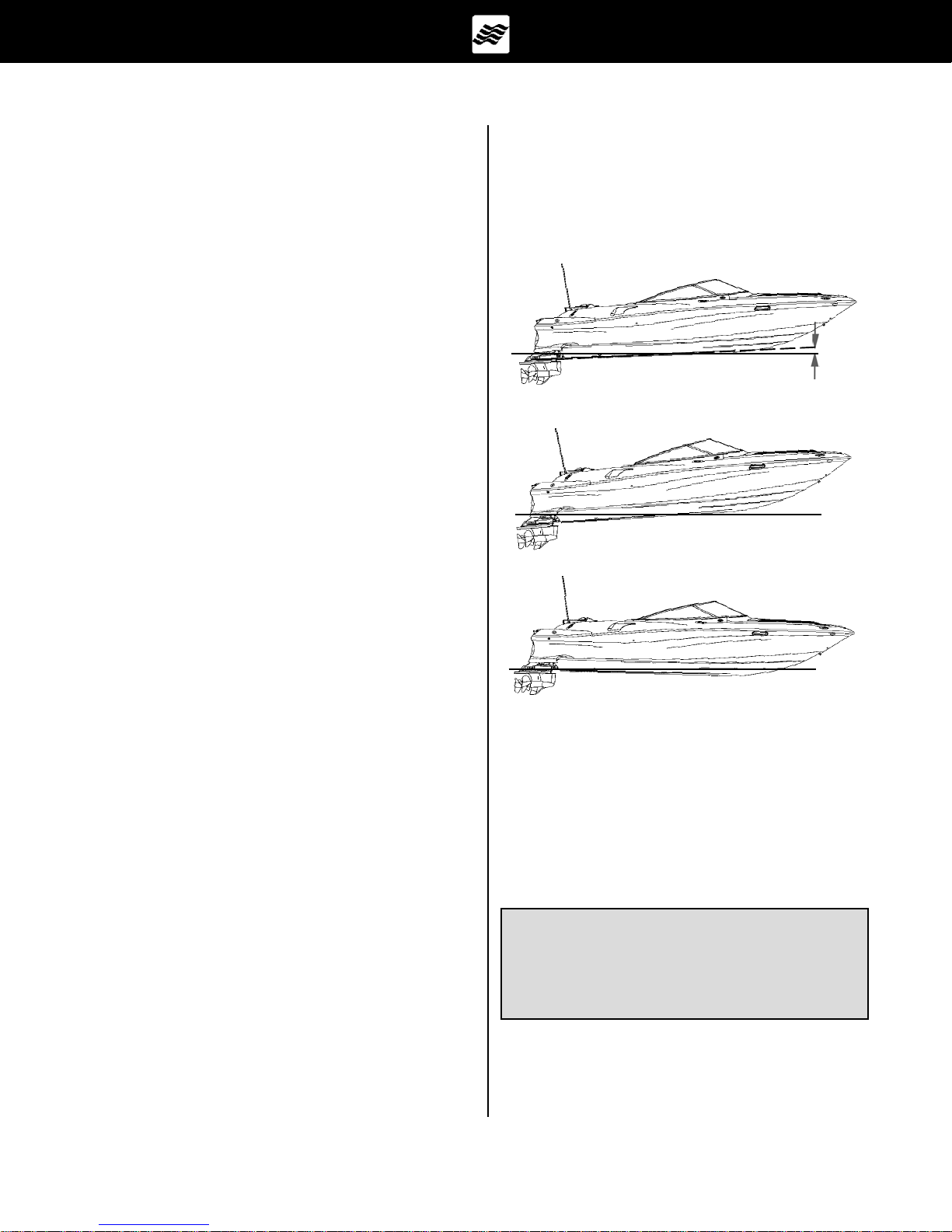
B - 5 RUNNING ANGLE & POWER TRIM/TILT
Hull planing surfaces have the least amount of drag at a
three to five degree angle with the water. This is the
preferred running angle when boating. The running angle
has a significant impact on top speed and handling. See
Figure B2. Heavy load or certain water conditions may
make it difficult to achieve the optimum running angle.
The running angle can be controlled through the use of
the power trim and trim tabs. See Section B-6, Trim
Tabs, for information on the use of trim tabs.
A. Power Trim
Trim angle is how far in or out, the drive or outboard
motor is positioned in relation to the bottom of the boat.
The trim angle of the drive or outboard engine has a
distinct affect on the running angle of the boat.
The power trim system permits control of the trim angle
of the drive or outboard motor relative to the boat, at the
touch of a button.
0
3
TO
0
Boat Properly Trimmed
Boat Too High - Trim Bow Down
Boat Too Low - Trim Bow Up
Figure B2: Running Angle
5
B. Power Tilt
Power tilt allows the operator to raise and lower the drive
or outboard motor for trailering, launching, and beaching. Additional information on power tilt can be found in
the engine operators manual included in the owners
packet
NOTICE
DO NOT operate the motor with the water intakes out of the water. Severe damage to the
engine systems can result. Consult the engine
operators manual for specific information.
Owners Manual
05/00
Section B
Page 3
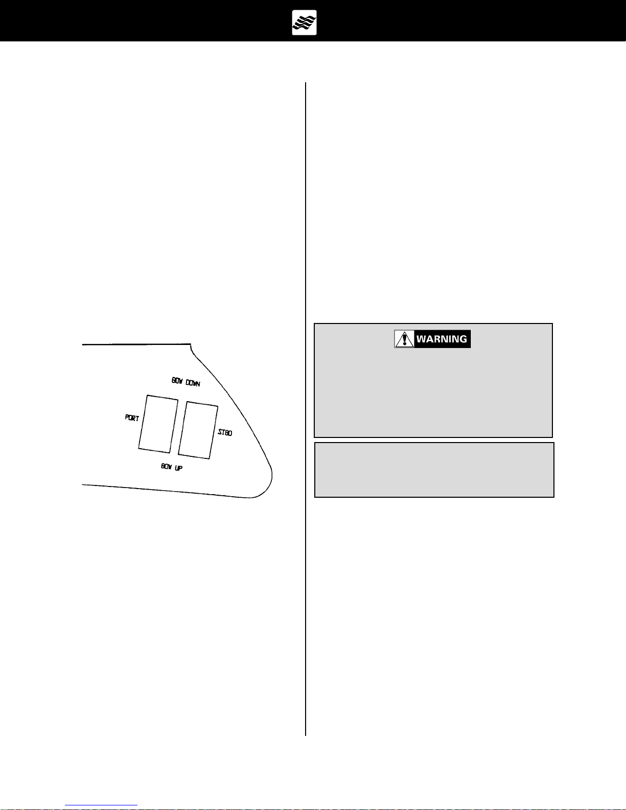
B - 6 TRIM TABS
Electric/hydraulic trim tabs are optional on some models
and help provide maximum control of the hull in all water
and load conditions. If used properly, trim tabs can:
a. Compensate for wind and load listing (level the boat
side to side).
b. Induce faster planing and help achieve optimum run-
ning angle (see Section B-5 Running Angle & Power
Trim/Tilt).
The proper use of electric/hydraulic trim tabs require a
basic understanding of trim tab operation and some practice in calm water.
The trim tab control uses two (2) momentary-type rocker
switches. The trim tab switches control the attitude or
position of the boat. See Figure B3.
Pressing the lower port trim tab switch will move the
port trim tab upward. This will result in the starboard
bow of the boat being allowed to rise.
Pressing the lower starboard trim tab switch will cause
the starboard trim tab to move upward and will result in
the port bow being allowed to rise.
Depressing the upper port trim tab switch will cause the
port trim tab to move downward and will force the starboard bow downward.
Depressing the upper starboard trim tab switch will cause
the starboard trim tab to move downward and will force
the port bow downward.
Always establish your intended heading and attain desired cruising speed before trying to adjust running attitude (using the trim tabs).
Always press the trim tab switches in short 1
second bursts. If depressed too long, you can
overcompensate, and potentially lose control.
DO NOT try to correct the situation by depressing the other upper trim tab switch. Instead,
raise the tab slightly by depressing the appropriate lower half of the trim tab switch.
Figure B3: Trim Tab Switches
Before leaving the dock and utilizing the trim tabs, ensure the trim tabs are in the full up position.
Depress both lower halves of the trim tab switches and
hold (for approximately 10 seconds) until the tabs are full
up.
A. Control Listing
Wind, loading and many other factors can result in the
boat tilting or leaning towards one side while running. This
is called listing and can be negated using trim tabs.
NOTICE
DO NOT depress both switches in opposite directions. This will cause a short in the trim tab
motor and blow a fuse.
After stabilization of speed and direction, depress the
upper half of the appropriate trim tab switch to achieve
a level side to side running attitude. Be sure to press
the correct trim tab switch to obtain the desired result.
After depressing a trim tab switch, always wait and allow time for the change in trim tab position to take effect. DO NOT continue to depress the trim tab switch
while awaiting trim tab reaction. By the time the effect is
noted, the trim tab will move too far and thus overcompensate.
Owners Manual
05/00
Section B
Page 4
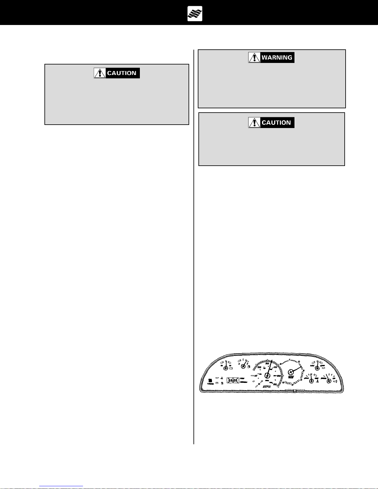
B. Induce Planing & Control Trim Angle
The use of trim tabs to attain quicker planing
should not be used by inexperienced boaters.
The combination of extreme inward drive position and extended trim tabs can dangerously
affect the boats handling under certain sea
conditions.
When running at high engine speeds, be sure
the trim tabs are in the full up position. Trim tab
action should be only enough to compensate for
any listing. Trim tab adjustments at high speeds
are extremely critical. Be prepared to slow down
should handling difficulties arise.
Trim tabs can also be used to facilitate faster planing
and allow better control of the running angle.
Before accelerating and trying to gain plane, depress
both upper trim tab switches. This will cause both trim
tabs to move downward and force the bow down when
running. This can also be used when running the boat
with a heavy load aboard.
Moving the trim tabs downward will increase the lift and
the boat will achieve plane faster, or stay on plane at a
lower engine and boat speed.
After gaining plane and establishing cruising speed,
depressing both lower trim tab switches will cause both
trim tabs to move upward and will allow the bow to rise.
This should be used to adjust the running attitude of the
boat to decrease the drag at cruising speed or above,
or when running in a following sea.
When running at an engine speed that results in the
boat falling off plane or causes the boat to plane inefficiently, lowering both tabs slightly (bow down) will improve the running angle and improve operating efficiency.
Optimum efficiency is obtained when operating at a 3 to
5 degree running angle. Utilizing too much Bow Down
trim tab can reduce operating efficiency and cause
substantial steering and handling difficulties. Be
extremely careful when running in a following sea. The
effect of trim tabs is amplified under such conditions.
Steering and handling difficulties can result from improper trim tab usage, especially in a following sea. If
unsure of proper trim tab positioning, raise the trim tabs
to the full-up position.
The combination of extreme inward drive position and extended trim tabs will cause a severe
bow down running angle. In certain sea conditions, this will limit the operators control over the
boat.
When running in a displacement (very slow speed) mode,
better efficiency will be obtained with the trim tabs in the
full-up position.
C. Trim Tab Maintenance
Check the fluid level of the trim tab reservoir often. Always keep the fluid level between the designated marks
on the trim tab pump-reservoir. Refer to the manufacturers information for specifications on the type of fluid to be
used and other operation and maintenance information.
B - 7 ENGINE INSTRUMENTATION
Four Winns is using a new style of instrumentation package on the Horizon and Sundowner models which consists of a module similar to units used in the automobile
industry. See Figure B4. This instrument module allows
the boat operator to constantly monitor the operational
condition of the engine. Close observation of the instru-
ments could save the engine from damage.
Figure B4: Horizon and Sundowner Dash Module
Owners Manual
05/00
Section B
Page 5
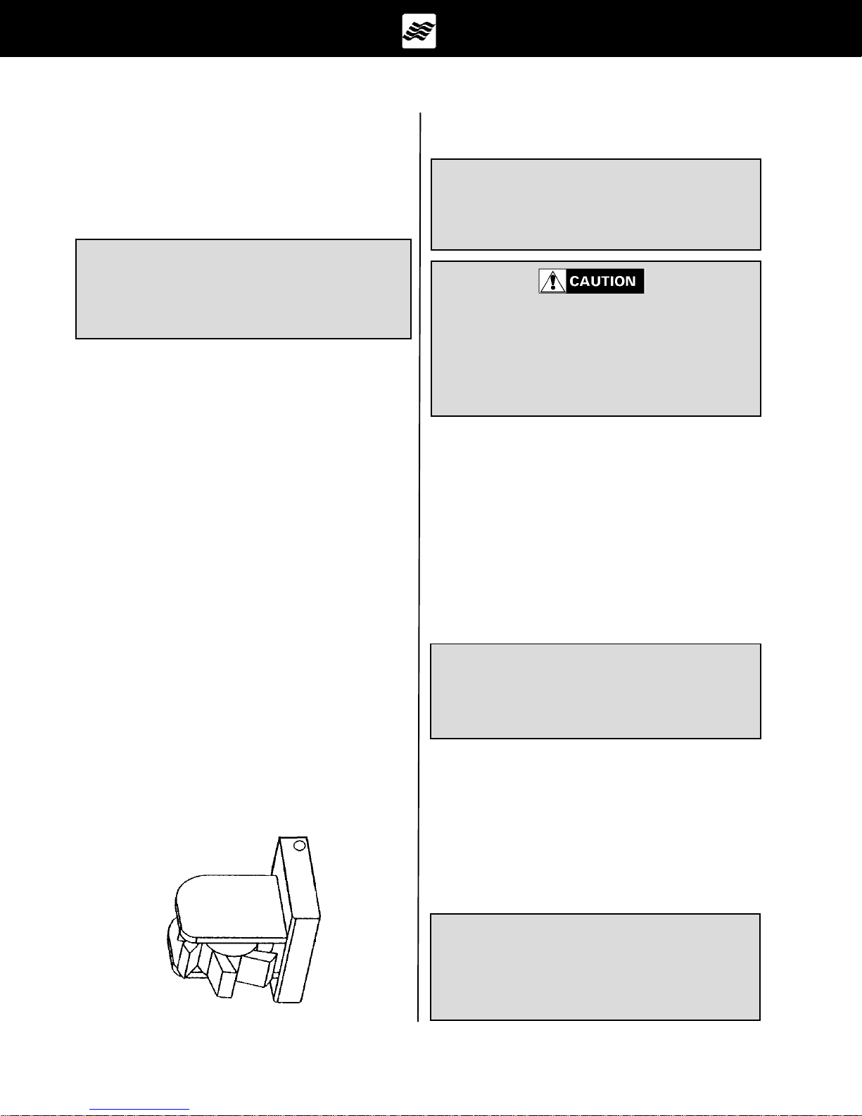
A. Tachometer
The tachometer indicates the speed of the engine in revolutions per minute (RPM). This speed is not the boat
speed or necessarily the speed of the propeller. The
tachometer may not register zero with the Ignition Key in
the OFF position.
NOTICE
Never exceed the maximum recommended
operating RPM of your engine. Maintaining
maximum, or close to maximum RPM for extended periods can reduce the life of the engine.
Some engines are equipped with devices that limit engine RPM in accordance with the oil pressure, or engine
temperature. Refer to the engine manual included in the
owners packet for additional information.
If the paddle wheel becomes fouled, the speedometer will not register. Clean the paddle wheel.
NOTICE
Speedometers are not precision instruments.
The indications are relative and should never
be used for navigational purposes or similar
critical situations.
DO NOT rely on the speedometer when trying to achieve a NO WAKE condition in a
harbor or other enclosed waterway. ALWAYS
reduce throttle! Speedometers are not effective at measuring low operational speeds. You
are responsible for damage caused by the
wake of your boat.
The tachometer must be set for different engines installed.
This is typically done at the factory with the aid of a
software program for the Four Winns/VDO module.
B. Speedometer
The electronic speedometer on the Horizons and
Sundowners have a paddle wheel sender. This speedo
sender provides accurate incremental readings (+/- 1.5
MPH) at low speeds as well as high speeds. The speedometer pick-up is located on the transom. See Figure
B5. The paddle wheel extends below the hull.
As the boat is moving, water strikes the wheel making it
spin. The information is relayed to the speedometer
which displays the speed in miles per hour (MPH). The
faster the boat speed, the faster the paddle wheel turns,
and the higher the speed indication on the speedometer.
New for 2000 is that the paddle wheel is capable of determining the water temperature. It is equipped with a
temperature sensor and relays this information to the
module for display.
C. Temperature Gauge
The temperature gauge monitors the cooling system
of the engine. A sudden increase in the temperature
could be a signal of a blocked cooling passage or a
water pump malfunction.
The temperature indicator on the Horizon and
Sundowner module monitors the coolant temperature.
If the coolant temperature rises to, or above 213 degrees F an alarm will sound a single beep every two
seconds and the temperature telltale will illuminate.
NOTICE
Operation of an overheated engine can result
in engine seizure. If an unusually high temperature reading occurs, shut the engine off
immediately.
D. Oil Pressure Gauge
The oil pressure gauge indicates the pressure in the
engine lubrication system. A drop in oil pressure is a
possible indication of oil pump or leakage problems. If
the oil pressure drops below 6 PSI (pounds per square
inch), a single beep will sound every 2 seconds and
the oil telltale will illuminate on the Horizon and
Sundowner dash module.
Figure B5: Paddle Wheel Speedo Sender
Owners Manual
05/00
NOTICE
Operation of an engine with abnormally low
oil pressure can lead to engine damage and
possible seizure. Have the engine serviced
immediately upon a reduced oil pressure indication.
Section B
Page 6
E. Voltmeter
The voltmeter monitors battery condition and thus alternator performance. See Section E for additional
information on electrical systems.
On the Horizon and Sundowner cluster, the voltmeter indicates the voltage at the cluster. If the voltage
is below 10 or above 16.5 VDC (volts of direct current) while the engine is running the telltale will light,
and the cluster will beep every 2 seconds.
The transducer is factory installed and is water tested. It
will be located in the bilge compartment to limit the effect
of water turbulence while underway.
NOTICE
DO NOT depend solely upon the depth sounder
for water depth. It is important to have
navigational charts of the waters in which you
are operating.
F. Fuel Gauge
The fuel gauge displays the level of fuel that is present
in the fuel tank. The fuel gauge will operate when the
ignition switch supplying power to the fuel gauge is in
the RUN position. At 1/6 of a tank, a low fuel warning
light will appear on the module.
Due to the mechanical nature of the fuel sender, variations in readings during various speeds of operation
may occur. This system is merely a relative indication
of the available fuel supply and not a calibrated instrument. Relative adjustments can be made by your Four
Winns dealer by bending the fuel sender float arm.
Refer to Section F-1e Fuel Sender for additional information.
NOTICE
Use only clean fuel of the type and grade
recommended by the engine manufacturer.
The use of incorrect or contaminated fuel can
cause engine malfunction and serious damage. Refer to Section F Fuel Systems for additional information.
G. Power Trim Gauge
Boats equipped with stern drives also have a power
trim gauge. This gauge provides a visual indication
of the inward-outward (trim angle) position of the
outdrive. There is not a trailer travel mode on the
gauge.
H. Depth Sounder
The depth sounder is standard equipment on the Horizon and Sundowner models. Readings can be displayed in feet or meters. The depth sounder has both
audible and visual alarm. The Four Winns/VDO clock
and depth operation is included below.
Do not rely on depth sounder to avoid submerged objects. Depth sounders provide a relative indication of water depth only.
1. 1999 Models Four Winns/VDO Clock and Depth
Operation
The LCD display has two main functions, clock and
depth functions. The operation and display of the functions is controlled by the SET and MODE push buttons. The programming of the VDO/FOUR WINNS
clock and depth operations of the new instrument module is described in the following:
Changing from clock to depth is done by pressing both
SET and MODE and holding them for 2 seconds. Pressing and holding both buttons again will toggle back to
clock function.
When using single push buttons, you will need to hold
the button in for 1/3rd of a second before the button will
be accepted. This is to prevent accidental inputs while
the boat is in motion.
2. Depth & Alarm
In depth mode, the display normally shows the current
depth. If dashes are shown, the depth sounder is not
generating valid data. If the current depth is less than
the alarm depth, the up & down arrow heads will flash
and the horn will chirp rapidly.
While in normal depth display, pressing the MODE button will cause the alarm depth to be displayed. After 10
seconds, the display will return to depth, or pressing
MODE a second time will return to depth display.
If the alarm is on (chirping), when the alarm depth is
displayed (using MODE) the audio part of the alarm
will be disabled. Reentering the alarm display will reenable the audio alarm. The flashing arrows will indicate an alarm condition whether the audio is on or off.
Owners Manual
05/00
Section B
Page 7
If the audio alarm is disabled, it will be re-enabled automatically when the boat moves into water deeper than
the alarm setting.
The alarm setting is always displayed as blinking digits, the current depth is displayed as steady (not blinking) digits. If the alarm screen is blank (set to zero),
the alarm is not enabled. If the depth screen shows
dashes the depth is zero or not found.
While in depth display, pressing the SET button will enter
the alarm setting mode. The alarm setting will blink
along with the down arrows on the display. Pressing
MODE will set the alarm deeper in 1 foot (0.3 meters)
steps. If the MODE button is held for 1 seconds the
digits will scroll.
Pushing SET again causes the up arrows to blink, indicating shallower settings. Pushing the MODE button
decreases the depth alarm setting.
Pushing SET a third time initiates Units Mode. While
in Units Mode, the current feet or meter telltale
flashes. Pushing the MODE button changes between
feet and meters display and changes the flashing telltale.
Pushing SET a fourth time returns to Depth Mode, or
after 30 seconds of no activity on the buttons, the display returns to depth mode automatically.
NOTICE
If you have set your depth incorrectly and you
are not sure how to reset your depth. You can
disconnect the positive (red) terminal from the
battery. After waiting a couple of seconds reconnect the positive terminal. This will clear
everything and allow you to reprogram your
shallow depth alarm and clock
3. Clock
Pressing SET again will cause the minutes to blink. The
MODE button now acts on the minutes. Each time a
new minute value is entered, the seconds are set to
zero.
Pressing SET a third time allows you to set the 12/24
hour mode. The display will show 24:12 with the active
mode blinking.
Pressing SET again returns to normal time keeping.
NOTICE
The clock has a three week auto shut-off capability. This will reduce the drain of your battery.
If your auto shut-off has occurred you will need to reset
your alarm depth as well as your clock. Turn the ignition key to ON to power up the module and follow the
preceding instructions regarding the depth and clock
programming instructions.
If you have any questions or need assistance please
contact VDO North America LLC at (540) 665-0100 or
Four Winns Customer Service at 231-775-1343.
4. 2000 Model Four Winns®/VDO Module Display
Settings and Operation
New for model year 2000, the LCD display has seven
(7) basic functions, clock, depth, distance log, trip log,
engine hours, trip hours, and water temperature. The
operation and display of the functions is controlled by
the MODE and SET push buttons. The programming
of all the FOUR WINNS®/VDO displays is shown in
the VDO Quick Start chart included at the end of
this section. Please note that the
ADJUST button on
the VDO Quick Start card is the SET button on the
Four Winns® dash panel. Also included in the follow-
ing is a detailed description of the steps involved in setting the different display functions:
The clock can display in 12 hour or 24 hour mode (military time). The time can be displayed in hours & minutes or in minutes & seconds. Pressing MODE while
in clock mode (not setting) toggles the hr-min and minsec mode. At an hour boundary the clock returns to
hour & minute display.
To set the clock, press SET. The clock display will be
in 24 hr. format (so that AM & PM are clear). Pressing
MODE will increase the hours. Holding MODE for more
than a second will cause the hours to scroll up.
Owners Manual
05/00
A. Clock
The Clock Display is selected by pressing the MODE
button. Note that during Clock Display the colon blinks
once per second.
The time of day is set by pressing and holding MODE
and SET for 2 seconds while in Clock Display mode.
The MODE button is then used to advance through the
time set features. Hours are set first, then minutes,
then 12/24 hour mode. The selected digits blink while
Section B
Page 8
 Loading...