

Four winns Vista (1994-2000 models), 238 Vista, 258 Vista, 278 Vista Owner's Manual

PREF ACE
This manual will acquaint you with the use and maintenance of your new Four Winns boat. The manual also
provides special information critical to the safety of the passengers, and longevity of the equipment. The information on the following page lists the conventions used to increase the visibility of these important messages. Also
included with this manual is the “Boating Basics, A Guide to Responsible Boating”. This publication covers all the
boating basics and should be read along with the Four Winns manual before operating your boat. Review this
information in detail.
Four Winns continually strives to improve its products. Unit specifications, including standard and optional
equipment are constantly being modified. Equipment availability is also subject to change. The most current and
accurate information available at the time of publication is included in this manual. Some variation in equipment,
description, location, and details can result.
The information in this manual focuses upon the equipment designed and manufactured by Four Winns on Vista
models. Utilize the information pertinent to your specific boat model. Equipment such as engines, and other
accessories are manufactured by others. The information provided in this manual is intended to be used in
conjunction with the information provided by the manufacturers. All information available at the time of manufacture has been included with this manual.
Read this manual carefully before operating your new boat. Many instructions may require direct performance of
the activity to fully understand the correct method. If you choose to read this manual at home, remember to take
it to the boat with you.
Y our Four Winns dealer knows your boat best and is interested in your complete satisfaction. Return to him for
service or other assistance. If you find it necessary to contact Four Winns directly , please write the office listed
below. Be sure to include the boat model, serial number , your daytime telephone number, and specifics of the
information desired.
This manual has been specifically developed for the 238, 258 & 278 Vista models. Please record the model and
serial number information below.
Model Serial Number
________________________ __________________________
This manual should be considered part of the boat. Should you sell the boat, pass this manual on to the new
owner. T ake special care of this manual. Certain information in this manual may not be available in a replacement
manual.
Thank you for joining the Four Winns family. We appreciate your purchase and welcome the opportunity to
demonstrate our commitment to you.
Four Winns Customer Service Department
925 Frisbie Street
Cadillac, Michigan 49601
616-775-1343
© Four Winns Boats 1995. All Rights Reserved.
Vista Owners Manual
10/93
Preface
Page 1

WARNING CONVENTIONS
This manual contains instructions critical to the safety of those aboard or the longevity of the equipment.
The conventions below have been adopted to increase the visibility of this information throughout the
manual.
This is used to indicate the presence of a hazard which WILL cause SEVERE injury or death if the
warning is ignored.
This is used to indicate the presence of a hazard which CAN cause SEVERE injury or death if the
warning is ignored.
This is used to indicate the presence of a hazard which WILL or CAN cause MINOR personal injury
or property damage if the warning is ignORED
NOTICE
This is used to notify people of installation, operation, or maintenance information which is important
but not hazard-related.
Vista Owners Manual
10/93
Preface
Page 2
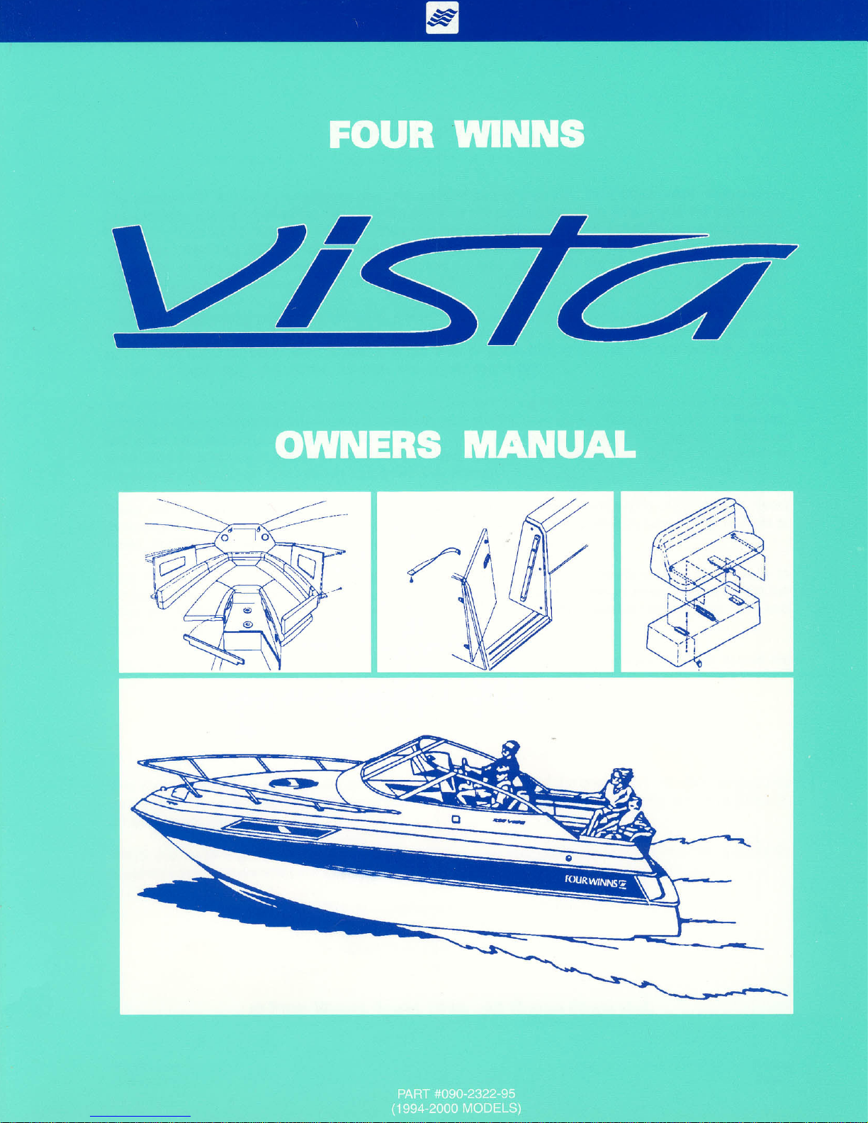
LABEL AND STICKER LOCA TIONS
The NMMA Capacity label, checklists and various warning stickers are placed at different locations on each
model for your safety . Additional warnings for fuel leakage, operating the blower , and other important
information will be imprinted or located on the dash. Many of these stickers and labels are not required by
the U.S. Coast Guard but are important to ensure the safe operation of your Four Winns boat. In addition,
the Hull Identification Number is molded into the gelcoat below the deck-hull joint in the starboard aft corner .
Below is a list corresponding to the various letters in Figure 1.
A. Transom Door Danger Label C. Procedure Checklist
B. Ladder Danger Label D. Equipment Checklist
DC,
A
B
Figure 1: Vista Models
Vista Owners Manual
10/93
Preface
Page 3

TABLE OF CONTENTS
WARRANTY AND SERVICE...................................................................................................................... 1
A - 1 FOUR WINNS WARRANTY POLICY ...................................................................................... 1
A - 2 HULL STRUCTURE WARRANTY ........................................................................................... 1
A - 3 WARRANTY REGISTRATION................................................................................................. 1
A - 4 TRANSFER OF WARRANTY ................................................................................................. 1
A - 5 PRE-OWNED UNIT REGISTRA TION ...................................................................................... 1
A - 6 INSURANCE COVERAGE ..................................................................................................... 2
A - 7 SERIAL NUMBER RECORD .................................................................................................. 2
A - 8 PRE-DELIVERY SERVICE..................................................................................................... 2
A - 9 REPLACEMENT P ARTS ........................................................................................................ 2
A - 10 CUSTOMER SA TISF ACTION SURVEY................................................................................... 2
A - 1 1 WINN GEAR .......................................................................................................................... 3
ENGINES AND INSTRUMENTA TION......................................................................................................... 1
B - 1 GENERAL.............................................................................................................................. 2
B - 2 ENGINE EXHAUST ................................................................................................................ 2
A. Carbon Monoxide ............................................................................................................. 2
B. Carbon Monoxide Monitor................................................................................................. 3
B - 3 ENGINE & DRIVE SYSTEM................................................................................................... 3
A. Engine ............................................................................................................................. 3
B. Stern Drive ....................................................................................................................... 3
B - 4 ENGINE FLUSHING ............................................................................................................... 4
B - 5 PROPELLERS....................................................................................................................... 4
A. Diameter .......................................................................................................................... 4
B. Pitch................................................................................................................................ 4
C. Prop Slip ......................................................................................................................... 4
B - 6 RUNNING ANGLE & POWER TRIM/TILT................................................................................. 5
A. Power Trim ...................................................................................................................... 5
B. Power Tilt ........................................................................................................................ 6
B - 7 TRIM TABS ............................................................................................................................ 6
A. Control Listing.................................................................................................................. 6
B. Induce Planing & Control Trim Angle................................................................................. 6
C. T rim T ab Maintenance ...................................................................................................... 7
B - 8 ENGINE INSTRUMENT ATION ................................................................................................. 7
A. T achometer...................................................................................................................... 8
B. Speedometer ................................................................................................................... 8
C. T emperature Gauge.......................................................................................................... 8
D. Oil Pressure Gauge ......................................................................................................... 9
E. Voltmeter ......................................................................................................................... 9
F. Fuel Gauge...................................................................................................................... 9
G. Power Trim Gauge ........................................................................................................... 9
H. Depth Gauge ................................................................................................................... 9
I. Gas Vapor Detector ......................................................................................................... 9
Vista Owners Manual
10/93
Section A
Page PB

J. Engine Hour Meter ........................................................................................................... 9
K. Ignition Switch ................................................................................................................. 9
L. Emergency Ignition Shut-Off ............................................................................................. 9
M. Alarm Systems .............................................................................................................. 10
N. Instrument Maintenance .................................................................................................. 10
CONTROL SYSTEMS ............................................................................................................................... 1
C - 1 GENERAL.............................................................................................................................. 1
C - 2 CONTROL OPERATION ......................................................................................................... 1
A. Standard Engines............................................................................................................. 1
B. Multi-port Fuel Injected Engines (EFI) ............................................................................... 1
C - 3 NEUTRAL SAFETY SWITCH.................................................................................................. 1
C - 4 CONTROL SYSTEM MAINTENANCE..................................................................................... 1
STEERING SYSTEMS............................................................................................................................... 1
D - 1 GENERAL.............................................................................................................................. 1
A. Rotary Steering ................................................................................................................ 1
B. Tilt S teering...................................................................................................................... 1
C. Power Steering................................................................................................................. 1
D - 2 PROPELLER TORQUE .......................................................................................................... 2
D - 3 STEERING SYSTEM MAINTENANCE.................................................................................... 2
ELECTRICAL SYSTEMS........................................................................................................................... 1
E - 1 GENERAL.............................................................................................................................. 1
E - 2 SINGLE BATTERY SYSTEM.................................................................................................. 1
E - 3 SINGLE ENGINE - DUAL BATTER Y SYSTEM........................................................................ 2
A. Installation ....................................................................................................................... 2
B. Operation ......................................................................................................................... 2
C. Battery Charger................................................................................................................ 3
E - 4 DUAL ENGINE - DUAL BA TTERY SYSTEM ........................................................................... 3
A. Installation ....................................................................................................................... 3
B. Operation ......................................................................................................................... 3
C. Battery Charger................................................................................................................ 4
E - 5 VOLTMETER ......................................................................................................................... 4
E - 6 12 VOLT ELECTRICAL EQUIPMENT ...................................................................................... 4
A. Helm Equipment .............................................................................................................. 4
B. Installation of Additional 12 Volt Equipment ....................................................................... 5
C. Interior Equipment ............................................................................................................ 6
E - 7 120 (220) VOLT ELECTRICAL SYSTEM ................................................................................. 6
E - 8 DOCKSIDE OPERATION........................................................................................................ 7
A. Shore Power Connections ................................................................................................ 7
B. 120 Volt AC Equipment .................................................................................................... 7
C. Reverse Polarity Indicator ................................................................................................. 8
D. Ground Fault Current Interrupters (GFCI)........................................................................... 9
E - 9 GENERA TOR OPTION ........................................................................................................... 9
E - 10 ELECTRICAL SYSTEM MAINTENANCE................................................................................ 10
A. Battery Maintenance....................................................................................................... 10
B. Electrical Wiring Maintenance ......................................................................................... 10
Vista Owners Manual
10/93
Section A
Page 2

E - 11 STRAY CURRENT CORROSION ........................................................................................... 10
A. General.......................................................................................................................... 10
B. Galvanic Corrosion ........................................................................................................... 11
C. Corrosion Prevention ........................................................................................................ 11
FUEL SYSTEMS ....................................................................................................................................... 1
F - 1 GASOLINE FUEL SYSTEMS ................................................................................................. 1
A. System T esting................................................................................................................ 1
B. Fuel Fills ......................................................................................................................... 1
C. Fuel Vents ....................................................................................................................... 1
D. Anti-Syphon Valves .......................................................................................................... 2
E. Fuel Gauge ...................................................................................................................... 2
F. Fuel Sender ..................................................................................................................... 2
G . Fuel Filters ...................................................................................................................... 2
H. Gas Vapor Detector ......................................................................................................... 2
I. Use and Maintenance ...................................................................................................... 3
F - 2 FUEL ST ANDARDS................................................................................................................ 3
A. Problems With Alcohol In Gasoline................................................................................... 3
B. Recommendations ........................................................................................................... 3
F - 3 FUELING INSTRUCTIONS...................................................................................................... 4
WA TER AND WASTE SYSTEMS............................................................................................................... 1
G - 1 GENERAL.............................................................................................................................. 1
G - 2 PRESSURIZED W A TER SYSTEM ......................................................................................... 2
A. Priming the System ......................................................................................................... 2
B. System Operation............................................................................................................ 2
C. Water Heating Systems ................................................................................................... 2
D. Using the Shower............................................................................................................. 3
G - 3 GREY WA TER SYSTEM........................................................................................................ 3
G - 4 SHORE WA TER CONNECTION ............................................................................................. 4
G - 5 TRANSOM WASHDOWN ...................................................................................................... 4
G - 6 H EA D S .................................................................................................................................. 4
A. Portable Head .................................................................................................................. 4
B. Porcelain Head ................................................................................................................ 4
C. Overboard Discharge ........................................................................................................ 5
D. Dockside Pumpout .......................................................................................................... 6
G - 7 SYSTEM MAINTENANCE ....................................................................................................... 6
A. Clean Vent s and Screens .................................................................................................. 6
B. Winterizing the Water System........................................................................................... 7
C. Winterizing the Waste System .......................................................................................... 7
VENTILA TION AND DRAINAGE SYSTEMS .............................................................................................. 1
H - 1 ENGINE COMP AR TMENT VENTILATION ............................................................................... 1
A. Gravity V entilation System ............................................................................................... 1
B. Forced Air Ventilation ....................................................................................................... 1
C. Engine Ventilation System Maintenance........................................................................... 1
H - 2 CABIN VENTILA TION ............................................................................................................. 1
Vista Owners Manual
10/93
Section A
Page PB

H - 3 HULL DRAINAGE SYSTEMS ................................................................................................. 2
A. Transom Drain ................................................................................................................. 2
B. Bilge Pumps.................................................................................................................... 2
C. Liner Drains ..................................................................................................................... 2
D. Bilge Compartment Drainage ............................................................................................ 2
E. Cockpit Drainage ............................................................................................................. 3
H - 4 CARBON MONOXIDE ............................................................................................................ 3
A. Definition of Carbon Monoxide .......................................................................................... 3
B. Properties and Characteristics of Carbon Monoxide .......................................................... 3
C. What Makes Carbon Monoxide ........................................................................................ 3
D. How a Person is Affected by Carbon Monoxide................................................................. 3
E. Effects of Carbon Monoxide.............................................................................................. 4
F. Symptoms ....................................................................................................................... 4
G. Treatment (Evacuate, V entilate, Investigate, T ake Corrective Action) .................................. 4
H. Inspection ........................................................................................................................ 4
I. Operation......................................................................................................................... 4
J. Boathouses, Sea Walls and Other Boats.......................................................................... 5
K. Backdrafting (S tation Wagon Effect) ................................................................................. 5
L. Cabin Appliances ............................................................................................................. 6
M. Ventilation of Accomodation S paces ................................................................................. 6
N. Altitude and Sea Conditions ............................................................................................. 6
O. Portable Generator Sets ................................................................................................... 6
P . Maintenance - Engine Performance .................................................................................. 6
Q. Maintenance - External Conditions ................................................................................... 6
R. CO Detection Systems .................................................................................................... 7
INTERIOR EQUIPMENT ............................................................................................................................ 1
I - 1 GALLEY EQUIPMENT.................................................................................................................. 1
A. Alcohol Stove ................................................................................................................... 1
B. Alcohol/Electric Stove ...................................................................................................... 1
C. Microwave Oven ............................................................................................................... 1
D. Ice Box ............................................................................................................................ 1
E. Refrigerator ...................................................................................................................... 1
I - 2 STEREO SYSTEM ....................................................................................................................... 1
I - 3 AIR CONDITIONING...................................................................................................................... 2
A. General............................................................................................................................ 2
B. Operation ......................................................................................................................... 2
C. Maintenance .................................................................................................................... 2
EXTERIOR AND SAFETY EQUIPMENT..................................................................................................... 1
J - 1 RAILS & DECK HARDWARE ................................................................................................. 1
J - 2 TRANSOM DOOR.................................................................................................................. 1
J - 3 COMP ANIONWA Y DOOR ...................................................................................................... 2
J - 4 WINDSHIELDS ...................................................................................................................... 2
A. Windshields and Cabin Windows...................................................................................... 2
B. Plexiglass........................................................................................................................ 3
J - 5 FOREDECK HATCH............................................................................................................... 3
J - 6 SWIM PLA TFORM ................................................................................................................. 3
J - 7 COCKPIT STORAGE ............................................................................................................. 3
Vista Owners Manual
10/93
Section A
Page 4

J - 8 ANCHOR STORAGE & OPTIONS .......................................................................................... 4
A. Anchor Storage ................................................................................................................ 4
B. Bow Roller Assembly ...................................................................................................... 4
C. Windlass ......................................................................................................................... 4
J - 9 NAVIGA TIONAL EQUIPMENT................................................................................................. 5
A. Compass ......................................................................................................................... 5
B. Depth Sounder ................................................................................................................ 5
C. Ship to Shore VHF Radio ................................................................................................. 5
D. Navigational Package ...................................................................................................... 5
E. Radar Arch....................................................................................................................... 5
J - 10 SPOTLIGHT ........................................................................................................................... 5
UPHOLSTERY .......................................................................................................................................... 1
K - 1 INTERIOR SEATING ............................................................................................................... 1
A. Cabin T ables .................................................................................................................... 1
B. V-berth Compartment....................................................................................................... 1
C. Dinette ............................................................................................................................. 1
D. Aft Cabin ......................................................................................................................... 1
K - 2 EXTERIOR SEATING.............................................................................................................. 2
A. Companion Helm Seat ..................................................................................................... 2
B. Stern Seat ....................................................................................................................... 3
C. Cockpit T ables ................................................................................................................. 4
K - 3 INTERIOR UPHOLSTERY CARE............................................................................................ 4
A. Cleaning Interior Fabric..................................................................................................... 4
B. Draperies ......................................................................................................................... 4
K - 4 EXTERIOR UPHOLSTERY CARE........................................................................................... 5
K - 5 REPLACEMENT UPHOLSTERY ............................................................................................ 6
K - 6 CARPET CARE ..................................................................................................................... 6
A. Interior and Exterior Carpet ............................................................................................... 6
B. Cleaning and Maintenance ............................................................................................... 6
C. Stain Removal .................................................................................................................. 6
WEA THER COVERS ................................................................................................................................. 1
L - 1 GENERAL INFORMA TION ..................................................................................................... 1
A. Bimini Top & Camper ....................................................................................................... 1
B. Cockpit Cover................................................................................................................... 2
L - 2 TRAILERING .......................................................................................................................... 2
L - 3 WINTER STORAGE ............................................................................................................... 2
L - 4 MAINTENANCE ..................................................................................................................... 2
L - 5 CARBON MONOXIDE ............................................................................................................ 3
FIBERGLASS AND HULL INFORMATION ................................................................................................ 1
M - 1 HULL DESIGN INFORMATION................................................................................................ 1
M - 2 FIBERGLASS CONSTRUCTION............................................................................................. 1
M - 3 EQUIPMENT INST ALLATION .................................................................................................. 1
M - 4 FIBERGLASS CARE & MAINTENANCE................................................................................. 2
A. General Maintenance ....................................................................................................... 2
B. Weathering Effects on Gel Coat ....................................................................................... 2
C. Stains .............................................................................................................................. 3
Vista Owners Manual
10/93
Section A
Page PB

M - 5 FIBERGLASS REPAIRS ........................................................................................................ 3
A. Scratches........................................................................................................................ 4
B. Gouges, Cracks, & Blisters.............................................................................................. 4
C. Osmotic Blistering ........................................................................................................... 5
M - 6 ANTI-FOULING PAINT ............................................................................................................ 5
M - 7 HULL SUPPORT.................................................................................................................... 6
WOODWORK AND COMPOSITES ........................................................................................................... 1
N - 1 TEAK ..................................................................................................................................... 1
N - 2 HIGH-PRESSURE LAMINATE CARE ..................................................................................... 1
N - 3 ASH....................................................................................................................................... 1
N - 4 BI R C H.................................................................................................................................... 1
N - 5 STAR BOARD ........................................................................................................................ 1
N - 6 FOUNTAINHEAD.................................................................................................................... 2
GENERAL MAINTENANCE ....................................................................................................................... 1
O - 1 WINTERIZA TION .................................................................................................................... 1
A. Prior to Lifting for Winter Layup......................................................................................... 1
B. After Lifting....................................................................................................................... 1
C. Prior to Winter Storage..................................................................................................... 2
O - 2 ENGINE FLUSH OUT............................................................................................................. 2
O - 3 GENERAL MAINTENANCE SCHEDULE................................................................................. 3
TRAILERS ................................................................................................................................................ 1
P - 1 GENERAL TRAILER INFORMATION ...................................................................................... 1
A. Regulations ...................................................................................................................... 1
B. Load Carrying Capacity ..................................................................................................... 1
C. Hitches ............................................................................................................................. 1
P - 2 TRAILER COMPONENTS ....................................................................................................... 2
A. Bunk Sup ports.................................................................................................................. 2
B. T ongue.............................................................................................................................. 2
C. Swivel Jack ....................................................................................................................... 2
D. Surge Brakes.................................................................................................................... 3
E. Winch............................................................................................................................... 4
F. Wheels ............................................................................................................................. 4
G. Spare T ire Carrier .............................................................................................................. 5
H. Lights .............................................................................................................................. 5
I. Tie-downs ........................................................................................................................ 5
P - 3 OPERATION .......................................................................................................................... 6
A. Hitching Trailer ................................................................................................................. 6
B. Backing Up....................................................................................................................... 7
P - 4 TRAILERING .......................................................................................................................... 7
A. Checklist ......................................................................................................................... 7
B. Tactics............................................................................................................................. 8
P - 5 MAINTENANCE ..................................................................................................................... 9
A. Care of Exterior Finish..................................................................................................... 9
B. Bunks............................................................................................................................. 9
C. Swivel Jack ..................................................................................................................... 9
D. Brake Actuator & Coupling Assembly .............................................................................. 9
Vista Owners Manual
10/93
Section A
Page 6

E. Winch............................................................................................................................. 9
F. Lights ............................................................................................................................. 9
G. Tie-downs ........................................................................................................................ 9
H. Wheels ............................................................................................................................ 9
I. Brakes............................................................................................................................ 10
J. Bearings ......................................................................................................................... 10
P - 6 AXLE INSPECTION & REP AIRS ............................................................................................ 10
A. Removal of Hub .............................................................................................................. 10
B. Bearing/Seal Inspection and Replacement ....................................................................... 1 1
C. Hub Reinstallation ........................................................................................................... 1 1
OPERATION ............................................................................................................................................. 1
Q - 1 GENERAL.............................................................................................................................. 1
Q - 2 COMPONENT SYSTEMS ...................................................................................................... 1
Q - 3 SAFETY EQUIPMENT ........................................................................................................... 1
Q - 4 PASSENGER SAFETY .......................................................................................................... 1
Q - 5 RULES OF THE ROAD .......................................................................................................... 1
Q - 6 LIGHTNING ............................................................................................................................ 1
Q - 7 DRINKING AND DRIVING ....................................................................................................... 2
Q - 8 PRE-CRUISE SYSTEM CHECK ............................................................................................. 2
A. Before Starting The Engines ............................................................................................. 2
B. After S tarting The Engine.................................................................................................. 2
Q - 9 ENGINE OPERA TIONAL PROCEDURES ............................................................................... 3
A. Before Starting ................................................................................................................. 3
B. Cold Engine Start............................................................................................................. 3
C. Warm Engine St arting ...................................................................................................... 3
D. Shifting ............................................................................................................................ 3
Q - 10 GROUNDING AND TOWING .................................................................................................. 4
Q - 11 BOATING EDUCA TION........................................................................................................... 5
A. Boating Courses .............................................................................................................. 5
B. Boating Manuals or Literature ........................................................................................... 5
C. Charts and Maps ............................................................................................................. 5
Q - 12 GLOSSARY........................................................................................................................... 5
FUEL LOG ................................................................................................................................................ 1
SERVICE LOG .......................................................................................................................................... 1
SERVICE INFORMA TION ......................................................................................................................... 1
ELECTRICAL SCHEMA TICS ..................................................................................................................... 1
Vista Owners Manual
10/93
Section A
Page PB

WARRANTY AND SERVICE
A - 1 FOUR WINNS W ARRANTY POLICY
The Four Winns Winning EdgeÔ Owner Protection Plan,
provides the new Four Winns purchaser with one of the
most comprehensive corporate commitments in the marine industry today. The Four Winns Owner Protection
Plan, defines the warranty coverage on all units manufactured by Four Winns. It thoroughly describes the warranty policies and those procedures to be followed to obtain
warranty coverage. Review the Four Winns Owner Protection Plan and limited warranty statements carefully .
All engines utilized in the Four Winns product are warranted by the engine manufacturer. Your Four Winns
dealer is authorized to repair your engines and will work
closely with the manufacturer to resolve any problems
you have.
A - 2 HULL STRUCTURE W ARRANTY
Each unit manufactured by Four Winns is encompassed
by a separate warranty providing specific coverage on the
hull structure. The Four Winns Owner Protection Plan
thoroughly describes this coverage.
A - 4 TRANSFER OF W ARRANTY
Four Winns confidence in the product and our warranty
commitments can extend long after the original purchaser
may choose to move on to a new boat. Four Winns
Limited Warranty coverage and Extended Protection Plan,
when applicable, are transferable to successive owners
of the boat. Registration of the second or successive
owners is required. The Four Winns Owner Protection
Plan thoroughly describes the action required to transfer
warranty coverage.
A - 5 PRE-OWNED UNIT REGISTRA TION
Section A-4 T ransfer of W arranty discussed the need to
properly register the purchase of a pre-owned boat with
Four Winns to transfer applicable warranty coverage.
Purchasers of all Pre-Owned Four Winns models are
encouraged to register ownership with Four Winns. To
register ownership of a “Pre-Owned Four Winns boat,”
provide Four Winns with your name, address, daytime
phone number, purchase date, and hull serial number of
the boat purchased.
A - 3 WARRANTY REGISTRA TION
A Four Winns Warranty Registration Card is attached to
the Four Winns Owner Protection Plan statement. Y our
Four Winns Dealer is responsible for completing and
mailing the warranty card at the time of purchase. This is
the sole basis for establishing proof of ownership of the
boat and trailer and corresponding warranty validation.
Registration of the boat and engines with the manufacturer is required by the Federal Boat Safety Act of 1971.
Other equipment manufacturers also require that their
products be registered with the respective companies.
These warranty registration cards are provided with this
manual.
If you wish to transfer warranty or an extended service
plan coverage, be sure to include a check to cover the
necessary fees.
The hull serial number is embossed into the starboard
side of the transom. The trailer serial number is imprinted
on an identification plate affixed to the trailer frame.
Registration of a Pre-Owned Four Winns boat does not
extend or in any way affect or modify the specific terms of
the Four Winns Owner Protection Plan or Limited Warranties.
We provide this service to the purchasers of Pre-Owned
Four Winns boats in the interest of better boating. Four
Winns welcomes every purchaser of a Four Winns boat,
new or used, to our family .
Vista Owners Manual
10/93
Section A
Page 1

A - 6 INSURANCE COVERAGE
A - 9 REPLACEMENT P ARTS
One of your responsibilities as a new boat owner is to
acquire proper insurance protection. Insurance should
include comprehensive and general liability coverage appropriate to your financial needs. Please contact your
local agent for assistance on insurance coverage.
A - 7 SERIAL NUMBER RECORD
The manufacturer, model, and serial number of major components are recorded during the assembly of each Four
Winns boat. Two copies of this completed form are included at the end of this section. One copy should be
removed and kept by the dealer in his records. This can
assist the dealer in processing warranty claims, or obtaining necessary information. The second copy should be
kept in this owners manual.
A - 8 PRE-DELIVERY SERVICE
Four Winns makes every effort to deliver your boat in ‘turn
key’ condition to the dealer . The process of transporting
and handling the boat necessitates certain inspections
and adjustments prior to delivery to you. Also, various
aspects of operation must be checked and adjusted
immediately prior to final delivery and use.
The selling Four Winns dealer must perform this thorough review of the boat and its numerous systems during
the commissioning or “dealer pre-delivery service” of the
craft.
Four Winns dealers are equipped with a Four Winns Parts
Manual that details the components of each model and
their appropriate part numbers. Many Four Winns dealers inventory common replacement components.
In addition, Four Winns maintains specific records on
the components used in the manufacture of each unit
and makes a concerted effort to maintain components
specifically to fill replacement part needs.
The Four Winns dealer from whom you purchased your
boat is in the best position to meet your needs. If he
does not have the needed item, he has the capability,
through direct facsimile contact with the Four Winns Customer Service Department, to obtain it quickly . Four Winns
will only sell replacement parts to established Four Winns
dealers. If you relocate and cannot find a Four Winns
dealer close to you, contact the Four Winns Customer
Service Department for information on the nearest dealer
in your area.
A - 10 CUSTOMER SA TISF ACTION SURVEY
Four Winns, in association with Outboard Marine Corporation, participate in an on-going market study of the purchasers of our products. Our concern and desire for your
complete satisfaction is genuine. Should you receive such
a survey , we would appreciate your comments and any
suggestions you may have. Each dealer, the product,
and our customer support services are rated based upon
the responses received.
A Four Winns Pre-Delivery Service Record form is provided with this manual. This form lists the many items
encompassed by the pre-delivery service previously described. The Four Winns Pre-Delivery Service Record is
a four-part form. The dealer is to check off the items as
they are completed, and complete the form as indicated
providing specific performance related information appropriately .
Y our Four Winns dealer will sign the Pre-Delivery Service
Record upon completion of the work. You will be asked
to sign this form upon accepting delivery of the boat. Both
you and your dealer are to retain one copy of the completed Four Winns Pre-Delivery Service Record. The other
two copies are to be mailed to the Four Winns Customer
Service Department.
Vista Owners Manual
10/93
A - 11 WINNGEAR
™
Show your colors! Four Winns offers a complete line of
sports clothing designed to complement your new boat.
Y our Four Winns dealer has a complete catalog and pricing.
Section A
Page 2

IMPORT ANT OPERATING INSTRUCTIONS
FOR GENERA TOR OPTION ONL Y
Caution is needed when operating or starting a generator on Four Winns 278 Vistas equipped with
hydro-lift mufflers. W ater can accumulate in the muffler if engine fails to start. Prolonged cranking
of the starter will pump water into the muffler system. Each additional attempt to start (that fails)
places more water into the exhaust, and will back up into the manifold and flow into the cylinders.
If the starter does not crank over the engine (after continued attempts have failed), there may be
water backed into a cylinder. This condition may be mistaken as a dead battery and immediate
action is necessary to prevent engine damage.
If the generator is hard starting, Four Winns recommends removing the drain plug in the muffler to
allow water to drain and have engine tuned up or repaired as soon as possible. Once the engine is
started, reinstall the drain plug.
DO NOT leave boat unattended with plug removed. Water may enter boat from
overboard.
T o locate the drain plug or muffler , refer to the generator manufacturer’s literature supplied with this
manual. If the generator does take on water , it is very important that immediate action is taken
to prevent engine damage. Contact your Four Winns or OMC dealer for assistance.
Vista Owners Manual
10/93
Section B
Page 1

ENGINE AND DRIVE SYSTEMS
B - 1 GENERAL
DO NOT attempt to service any engine or drive
component without being totally familiar with the
safe and proper service procedures. Certain moving parts are exposed and can prove dangerous
to one unfamiliar with the operation and function
of the equipment.
Four Winns does not manufacture engines or drives.
Because of the technical nature of the engine and drive
systems, all manufacturers of these items require that
warranty and service problems be taken directly to an
authorized dealer for resolution. The Four Winns dealer
from whom you purchased your boat, will handle all warranty and service matters with the engine manufacturer
for you.
In compliance with the Federal Boat Safety Act of 1971
all engine manufacturers require their products to be registered. A registration card is furnished with each new engine. When selling a Four Winns boat, the dealer, along
with the purchaser, should complete the information requested on these cards and return them to the respective
engine manufacturers. Engine registration cards are provided with the engine and will usually be found with the
boat literature.
Each manufacturer of the various marine power components provides an owners information manual with their
product. This publication is included with this manual. It
is important that you read the manual(s) carefully and
become completely familiar with proper care and operation of the engine and drive system. Be sure to read the
section on winterization. Replacement costs associated
with frozen engine blocks, drive systems and other components are quite substantial.
Also review the other sections in this manual, especially
Sections F on Fuel Systems, and Section C on Control
Systems.
B - 2 ENGINE EXHAUST
A. Carbon Monoxide
The carbon monoxide in exhaust fumes can be hazardous. It is important for you and your passengers to be
aware of the potential safety hazard created by exhaust
fumes. Familiarize yourself with the symptoms of individuals overcome by carbon monoxide, and most importantly , ways you can protect yourself and your guest s.
DO NOT inhale exhaust fumes! Exhaust contains carbon monoxide which is colorless and
odorless. Carbon monoxide is a dangerous gas
that is potentially lethal.
Persons overcome by carbon monoxide may
exhibit the following symptoms:
a. Watering and itchy eyes
b. Flushed appearance
c. Throbbing temples
d. Inattentiveness
e. Inability to think coherently
f. Ringing in the ears
g. Tightness across the chest
h. Headache
i. Drowsiness
j. Incoherence
k. Nausea
l. Dizziness
m. Fatigue
n. Vomiting
o. Collapse
p. Convulsion
IF YOU THINK EXHAUST FUMES ARE ENTERING
YOUR BOA T , DETERMINE THE CAUSE AND HA VE
IT CORRECTED IMMEDIA TEL Y!
Vista Owners Manual
10/93
Section B
Page 2

The following suggestions can help prevent exhaust fumes
from entering the boat:
1. DO NOT allow the boat to remain stationary with the
engines running for an extended period of time.
2. Use extreme caution while operating the engines in
confined areas such as enclosed slips, congested
piers, or in any area where the exhaust outlets are
facing or near a bulkhead or wall structure of any
kind. Operation under such conditions could easily
lead to exhaust gasses (carbon monoxide) entering
even though you may have all the hatches, windows,
doors and portholes closed.
3. Never operate your generator while the boat is moored
against any other boat, dock or wall structure that is
against or near the exhaust outlet. Again, operation
under such conditions could easily lead to exhaust
gasses (carbon monoxide) entering your boat or the
boat to which you are moored, even though you may
have all the hatches, windows, doors, and portholes
closed.
6. If possible, ventilate your cabin while under way.
Open a forward hatch or window to allow air to travel
through the cabin. Be very careful of operating the
boat with the cabin door or windows that face aft,
open. The natural vacuum created during operation
may allow exhaust gasses to be drawn into the cabin.
NOTICE
Current deck hatches are designed to allow ventilation when
locked in a partially open position.
7. Inspect the engine exhaust system frequently for water
and exhaust gas leakage, hose deterioration, and
loose hose clamps. See Section O General Maintenance for additional information.
8. Have a competent marine engine service technician
inspect your exhaust system whenever your boat is
in for service, or if you notice a change in the sound
of your engines.
For additional information, refer to Section H-4 Carbon
Monoxide.
4. Under certain conditions, exhaust gases can enter
the boat through the sink drains. Each sink drain
has a water trap installed to help prevent this. To be
effective, the sink drains must have water in them.
Normal use of the sinks will provide the water needed
for this to occur.
5. Persons sleeping can be easily overcome by carbon
monoxide because they are unaware of its presence.
Sleeping while the engines or generator are running
is not recommended. If persons are sleeping aboard
while underway, or while the generator is running,
those awake should monitor for carbon monoxide
accumulation in the cabin; especially the sleeping
areas. Open forward facing windows or deck hatches
to provide fresh air ventilation. Keep hatches, windows, and doorways that face aft or towards the exhaust discharge closed.
NEVER operate the propulsion engine(s) or generator while everyone on-board is sleeping. Fatal
carbon monoxide poisoning can occur.
B. Carbon Monoxide Monitor
A carbon monoxide (CO) monitor will sound an alert should
carbon monoxide reach an unsafe level in the cabin of
your Four Winns boat. The CO Monitor is optional equipment on all Vista models and is usually located on the aft
cabin wall. If a CO monitor is installed, refer to the manufacturer’s literature included with this manual.
B - 3 ENGINE & DRIVE SYSTEM
A. Engine
Consult the Engine Owners manual provided with this
manual for operation and maintenance information.
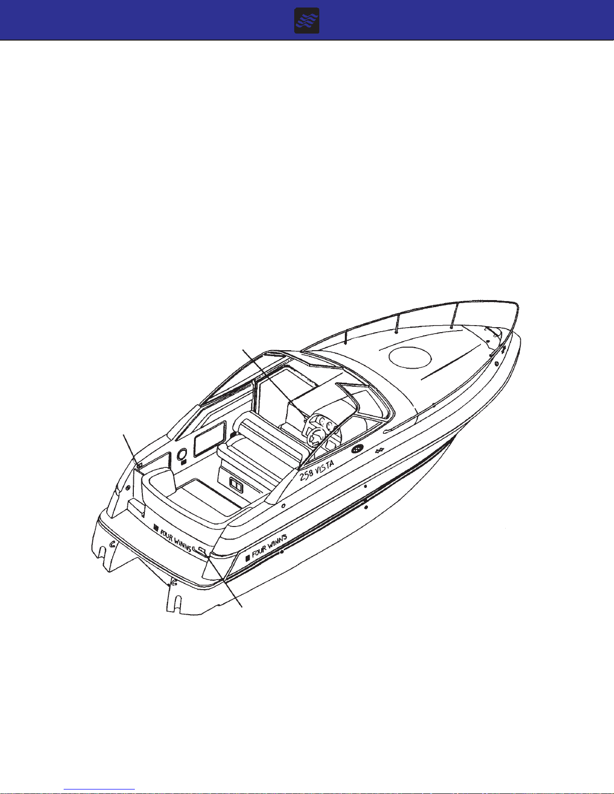
B. Stern Drive
A stern drive or inboard/outboard propulsion system has
a piston engine equipped with special marine components
mounted near the transom and coupled to an external
outdrive-type transmission unit. Shifting is performed
within the outdrive gear case. This type of system is
depicted in Figure B1.
Vista Owners Manual
10/93
Section B
Page 3
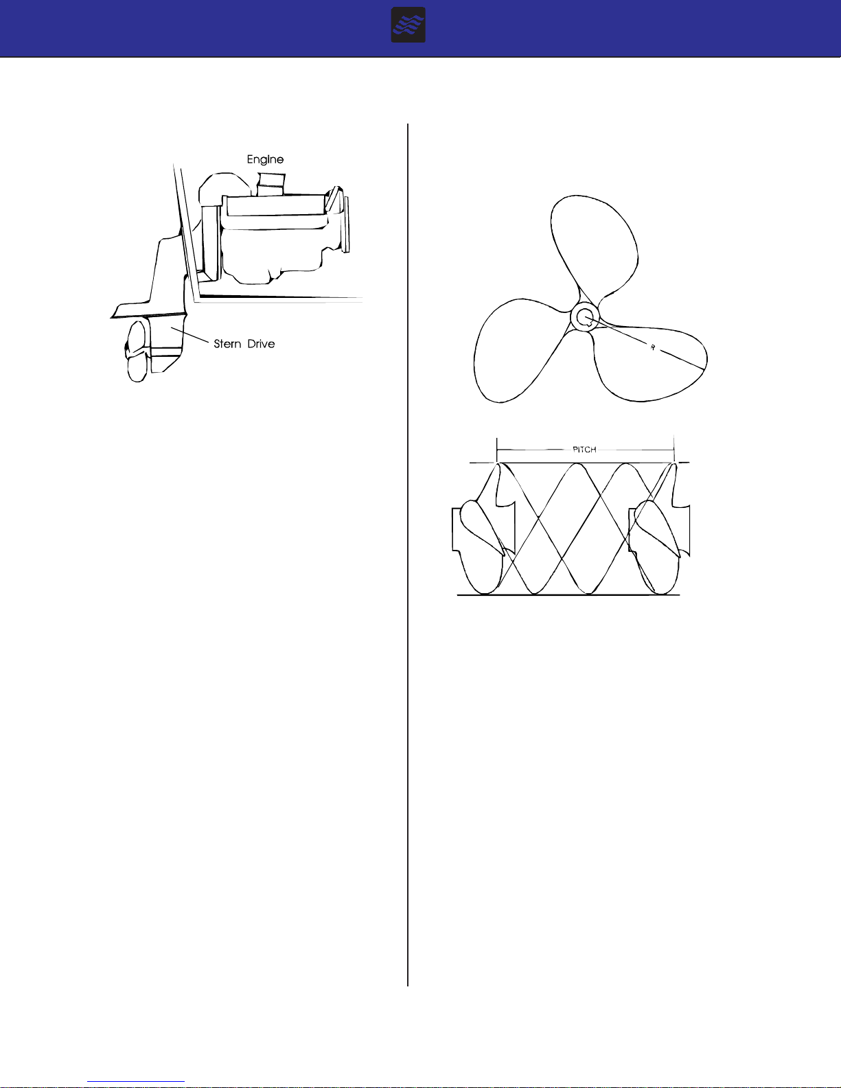
Figure B1: Stern Drive
Consult the Engine Owners manual for additional information on stern drives.
B - 4 ENGINE FLUSHING
The engine flush out option is offered on all Vista models.
The engine flushing kits attach permanently to the engine. A fresh water supply can be connected to the engine with the boat in the water. It is not intended for use
with the boat out of the water. This option is useful to
flush the engine cooling system of unwanted salt residue.
The flush out kit should only be used with the boat in the
water and the engine OFF . See Section O General Maintenance for flushing procedures.
B - 5 PROPELLERS
Knowledge of the propeller is most easily gained through
better understanding of the terminology used to refer to
the aspects of propeller size and performance.
A. Diameter
Diameter is twice the distance from the center of the prop
shaft to the extreme tip of a propeller blade. Increasing or
decreasing propeller size will have a direct bearing on the
RPM’s an engine will develop. This is due to the greater
amount of propeller blade surface in contact with the water. See Figure B2.
Figure B2: Propeller Pitch & Diameter
B. Pitch
Pitch is a measure of helix angle, or angle of attack, of
the rotating blade. Pitch is easily understood if one imagines the propeller rotating through a semi-solid such as
butter or gelatin. The distance the propeller will travel in
one revolution is called “Pitch.” Increasing or decreasing
pitch will also have a direct bearing on engine RPM’s
because of the greater bite taken by the blade with each
rotation. See Figure B2.
C. Prop Slip
When traveling through water a propeller is unable to get
a complete bite because of the fluidity of water. “Prop
Slip” is usually expressed as a percent of the computed
theoretical speed. T wentyfive to thirty-five percent prop
Vista Owners Manual
10/93
Section B
Page 4
slip is common for a cruiser-type boat operating at cruising speed.
Therefore the deduction can be made that a propeller, of a
certain diameter, with a 10 inch pitch, rotating at 3600
revolutions per minute, with a prop slip of 30%, would move
the boat at a rate of 24 miles per hour.
Changing either diameter or pitch will have an effect on
engine speed and prop slip, and in turn, directly effect the
performance of a boat. The propeller(s) included with each
Four Winns boat provide the best general performance
based on data obtained from on-the-water testing of that
model. V ariations in load, operating conditions,
environment, the individual engine and hull performance
may necessitate the purchase and use of another
propeller(s).
Under your normal load conditions, the engine(s) should
turn within the maximum RPM range when at full throttle.
If the engine(s) exceeds the recommended RPM, an increase in pitch or diameter is required. If the engine RPM
is too low, a decrease in pitch or diameter is required.
An engine that is not developing full power and the load
carried in a boat will directly affect performance of the
engine. Always be sure the engine is properly tuned and
load conditions are those normally experienced, before
changing propellers.
The running angle can be controlled through the use of
power trim and trim tabs. See Section B-6 Trim Tabs,
for information on the use of trim tabs.
NOTICE
For twin engine installations, always check drive
shaft rotation before propeller installation. A right
hand rotation propeller must be installed on the
stern drive to the starboard engine. Similarly , a
left hand prop must be installed on the port stern
drive.
For additional information on factors affecting performance,
please consult your Four Winns dealer .
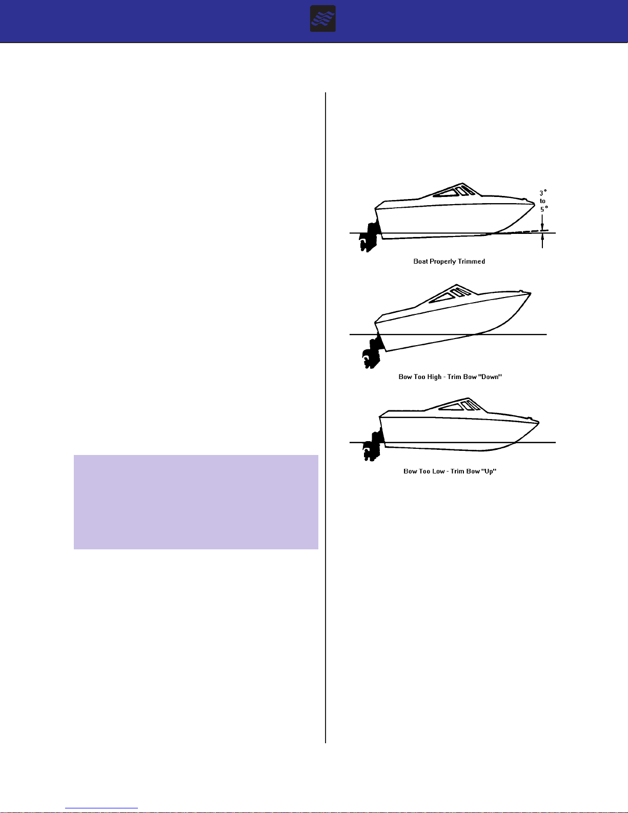
B - 6 RUNNING ANGLE & POWER TRIM/TIL T
Hull planing surfaces have the least amount of drag at a
three to five degree angle with the water. This is the preferred running angle when boating. The running angle has
a significant impact on top speed and handling. Heavy
load or certain water conditions may make it difficult to
achieve the optimum running angle. See Figure B3.
Figure B3: Running Angle
A. Power Trim
Trim angle is how far in or out, the lower unit is positioned in relation to the bottom of the boat. The trim
angle of the lower unit has a distinct affect on the running
angle of the boat.
The power trim system permits control of the trim angle
of the drive unit relative to the boat, at the touch of a
button.
It allows the drive unit to be raised (trimmed out) for shallow water operation. Power trim also allows the operator
to adjust the drive unit while underway to provide the
ideal running angle for a given load and water condition.
Additional information can be found in the Engine Owners manual.
Vista Owners Manual
10/93
Section B
Page 5

B. Power Tilt
Power tilt allows the operator to raise and lower the drive
unit for trailering, launching, and beaching. Additional
information on power tilt can be found in the engine
manufacturer’s manual included with this manual.
NOTICE
DO NOT operate the engine with the stern drive
tilted up. Severe damage to the engine drive
system can result. Consult the Engine Owners
manual for specific information.
B - 7 TRIM T ABS
Electric/hydraulic trim tabs are optional and help provide
maximum control of the hull in all water and load conditions. If used properly , trim tabs can
a. Compensate for wind and load listing (level the boat
side to side).
b. Induce faster planing and help achieve optimum run-
ning angle (see Section B-6 Running Angle & Power
Trim/Tilt)
Pressing the lower starboard trim tab switch will cause
the starboard trim tab to move upward and will result in
the port bow being allowed to rise.
Depressing the upper port trim tab switch will cause the
port trim tab to move downward and will force the starboard bow downward.
Depressing the upper starboard trim tab switch will cause
the starboard trim tab to move downward and will force
the port bow downward.
Always establish your intended heading and attain desired cruising speed before trying to adjust running attitude (using the trim tabs).
Always press the trim tab switches in short 1/2
second bursts. If depressed too long, you can
overcompensate, and potentially lose control. DO
NOT try to correct the situation by depressing
the other upper trim tab switch. Instead, raise
the tab slightly by depressing the appropriate
lower half of the trim tab switch.
The proper use of electric/hydraulic trim tabs requires a
basic understanding of trim tab operation and some practice in calm water.
The trim tab control uses two (2) momentary-type rocker
switches. The trim tab switches control the attitude or
position of the boat. The trim tab switches are labeled by
position such as “Bow Up” and “Bow Down”. They are
also labeled for “Port” and “Stbd”. When depressed, the
label indicates what happens to the bow of the boat.
Before leaving the dock and utilizing the trim tabs, ensure the trim tabs are in the full up position. Depress
both lower halves of the trim tab switches and hold (for
approximately 10 seconds) until the tabs are full up.
A. Control Listing
Wind, loading and many other factors can result in the
boat tilting or leaning towards one side while running.
This is called listing and can be negated using trim tabs.
Pressing the lower port trim tab switch will move he port
trim tab upward. This will result in the starboard bow of
the boat being allowed to rise.
After stabilization of speed and direction, depress the upper
half of the appropriate trim tab switch to achieve a level
side to side running attitude. Be sure to press the correct
trim tab switch to obtain the desired result.
After depressing a trim tab switch, always wait and allow
time for the change in trim tab position to take effect. DO
NOT continue to depress the trim tab switch while awaiting
trim tab reaction. By the time the effect is noted, the trim
tab will move too far and thus overcompensate.
B. Induce Planing & Controlling Trim Angle
Trim tabs can also be used to facilitate faster planing and
allow better control of the running angle.
Before accelerating and trying to gain plane, depress both
upper trim tab switches. This will cause both trim tabs to
move downward and force the bow down when running.
This can also be used when running the boat with a heavy
load aboard.
Vista Owners Manual
10/93
Section B
Page 6
C. Trim Tab Maintenance
The use of trim tabs to attain quicker planing
should not be used by inexperienced boaters. The
combination of extreme inward drive position and
extended trim tabs can dangerously affect the
boats handling under certain sea conditions.
Moving the trim tabs downward will increase the lift and
the boat will achieve plane faster, or stay on plane at a
lower engine and boat speed.
After gaining plane and establishing cruising speed, depressing both lower trim tab switches will cause both trim
tabs to move upward and will allow the bow to rise. This
should be used to adjust the running attitude of the boat
to decrease the drag at cruising speed or above, or when
running in a following sea.
When running at an engine speed that results in the boat
falling off plane or causes the boat to plane inefficiently,
lowering both tabs slightly (bow down) will improve the
running angle and improve operating efficiency .
Optimum efficiency is obtained when operating at a 3 to 5
degree running angle. Utilizing too much “Bow Down”
trim tab can reduce operating efficiency and cause
substantial steering and hand-ling difficulties. Be extremely
careful when running in a following sea. The effect of trim
tabs is amplified under such conditions. Steering and
handling difficulties can result from improper trim tab usage, especially in a following sea. If unsure of proper trim
tab positioning, raise the trim tabs to the full-up position.
Check the fluid level of the trim tab reservoir often. Always keep the fluid level between the designated marks
on the trim tab pump-reservoir . Refer to the manufacturers information for specifications on the type of fluid to be
used and other operation and maintenance information.
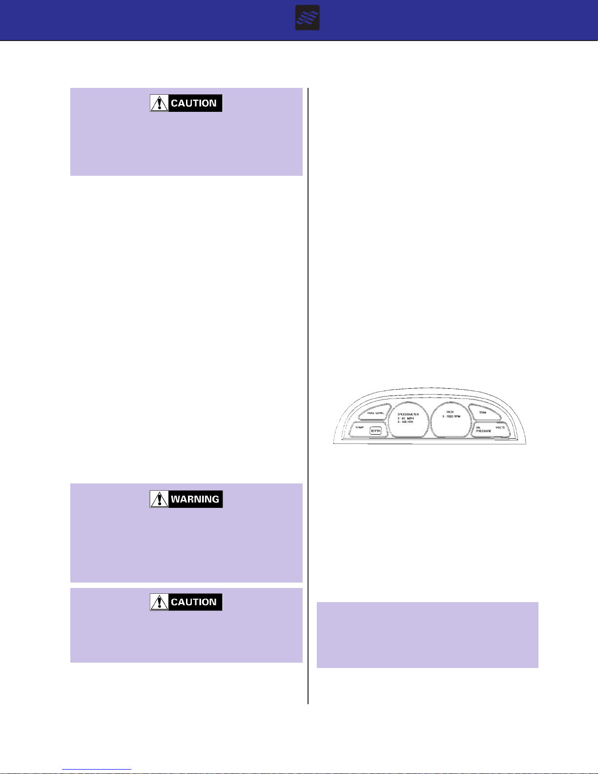
B - 8 ENGINE INSTRUMENT ATION
The helm station is equipped with a complete set of engine instruments. These instruments allow the pilot to
constantly monitor the operational condition of the engine. Close observation of these instruments could save
the engine from damage.
Four Winns is using a new style of instrumentation package which consists of a module similar to units used in
the automobile industry . See Figure B4. This is limited
to the 238 and 258 Vista models. The 278 Vista will
have standard instrumentation with gauges in the shroud
or dash panel.
Figure B4: 238 & 258 Vista Dash Module
The following general information on gauges applies to
all Vista models.
When running at high engine speeds, be sure
the trim tabs are in the full up position. Trim tab
action should be only enough to compensate for
any listing. Trim tab adjustments at high speeds
are extremely critical. Be prepared to slow down
should handling difficulties arise.
The combination of extreme inward drive position
and extended trim tabs will cause a severe bow
down running angle. In certain sea conditions,
this will limit the operator’s control over the boat.
When running in a displacement (very slow speed) mode,
better efficiency will be obtained with the trim tabs in the
full-up position.
Vista Owners Manual
10/93
A. Tachometer
The tachometer indicates the speed of the engine in revolutions per minute (rpm). This speed is not the boat
speed or necessarily the speed of the propeller. The
tachometer may not register zero with the Ignition Key in
the OFF position.
NOTICE
Never exceed the maximum recommended
operating RPM of your engine. Maintaining maximum, or close to maximum RPM for extended
periods can reduce the life of the engine.
Section B
Page 7
Some engines are equipped with devices that limit engine rpm in accordance with the oil pressure or engine
temperature. Refer to the Engine Owners manual for
additional information.
When winterizing the boat, the speedometer tubing must
be drained of water. Disconnect the speedometer hose
at the pick-up assembly and at the gauge and blow
through the tubing to remove the water.
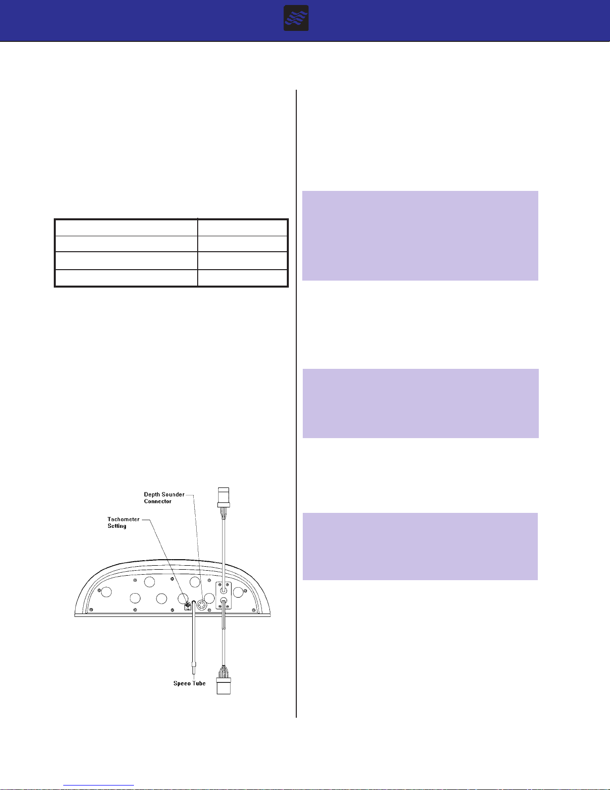
The tachometer must be set for different engines installed.
The tachometer setting screw or knob is located on the
backside of the gauge. See Figure B5. The tachometer
should be set according to the information in Table I.
Table I: Tachometer Adjustments
Engine Size T ach Setting
4 Cylinder 2
6 Cylinder 3
8 Cylinder 4
B. Speedometer
The speedometer is a water pressure sensitive unit. It
has a pick-up (pitot tube) assembly mounted on the transom and a small plastic hose that connects it to speedometer gauge on the dash. The pitot tube extends below
the hull. Water strikes the tube inlet and creates positive
pressure. The faster the boat speed, the greater the pressure, and the higher the speed indication on the speedometer.
If the pick-up becomes clogged, the speedometer will not
register. Clean the opening with a piece of wire or disconnect the tubing and blow out the pick-up with compressed
air
Speedometers are not precision instruments. The indications are relative and should never be used for navigational purposes or similar critical situations
NOTICE
DO NOT rely on the speedometer when trying to
achieve a “NO WAKE” condition in a harbor or
other enclosed waterway. ALWAYS reduce
throttle! Speedometers are not effective at measuring low operational speeds. Y ou are responsible for damage caused by the wake of your boat.
C. Temperature Gauge
The temperature gauge monitors the cooling system of
the engine. A sudden increase in the temperature could
be a signal of a blocked cooling passage or a water pump
malfunction.
NOTICE
Operation of an overheated engine can result in
engine seizure. If an unusually high temperature reading occurs, shut the engine off immediately.
D. Oil Pressure Gauge
The Oil Pressure Gauge indicates the pressure in the
engine lubrication system. A drop in oil pressure is a
possible indication of oil pump or leakage problems.
Figure B5: Rear View of 238 & 258 Vista Module
Vista Owners Manual
10/93
NOTICE
Operation of an engine with abnormally low oil
pressure can lead to engine damage and possible seizure. Have the engine serviced immediately upon a reduced oil pressure indication.
E. Voltmeter
The voltmeter monitors battery condition and thus alternator performance. See Section E Electrical Systems
for additional information on voltmeter operation.
F. Fuel Gauge
The Fuel Gauge displays the level of fuel that is present
in the fuel tank. Refer to Section E Electrical Systems
and Section F Fuel System for additional information.
Section B
Page 8

Due to the mechanical nature of the fuel sender, variations in readings during various speeds of operation may
occur. This system is merely a relative indication of the
available fuel supply and not a calibrated instrument.
Relative adjustments can be made by bending the fuel
sender float arm.
NOTICE
Use only clean, dry fuel of the type and grade
recommended by the engine manufacturer. The
use of incorrect or contaminated fuel can cause
engine malfunction and serious damage. Refer
to Section F Fuel System for additional information.
G. Power Trim Gauge
The Power Trim Gauge provides a visual indication of the
inward-outward (trim angle) position of the outdrive.
H. Depth Gauge
The Depth Gauge is standard equipment on the Vista
models. The depth gauge on the 238 & 258 Vistas will
read depth only and cannot be adjusted. It is installed in
the dash module.
L. Emergency Ignition Shut-Off
The emergency ignition shut-off switch is provided on most
models. If equipped, the switch has a lanyard (cord) attached to a clip which must be in position for the engine(s) to run. See Figure B6. The helmsman can attach the cord to a belt loop, life jacket, etc. If the clip is
not in position, the starter and other systems will still
operate but the engine will not start. Should the operator move beyond the range of the lanyard, the engine(s)
will be shut off preventing the boat from becoming a runaway . If the lanyard is too long, it can be shortened by
knotting or looping it. DO NOT cut and retie the lanyard.
NOTICE
DO NOT attach the lanyard to clothing that will
tear away before the lanyard is pulled from the
switch to stop the engine.
I. Gas Vapor Detector
The Gas Vapor Detector is optional equipment on the
278 Vista only . The gauge will mount in the dash. Additional information can be found in Section F-1h in this
manual.
J. Engine Hour Meter
Engine hour meters are available on all Vista models and
provide a numeric record of elapsed engine operating time.
This information is important in determining scheduled
maintenance intervals, ships log data, cruise information,
etc. If so equipped, the hour meter will be located in the
engine compartment.
K. Ignition Switch
The ignition switch has three positions: OFF, RUN, and
START. The START position is spring loaded and the
key should be held in this position until the engine starts.
The key will return to the RUN position once released.
Always turn the key to the OFF position when the engine
is not running. This will prevent discharging of the
battery(s). Additional information on ignition switch operation is covered in Section Q Operation, of this manual.
Figure B6: Emergency Stop Switch
The emergency stop switch can only be effective when in
good working condition. Observe the following:
1. Lanyard must always be free of entanglements that
could hinder its operation.
2. Once a month, check the switch for proper operation. With engine running, pull lanyard. If the engine
does not stop, see your Four Winns dealer.
3. Once a month, inspect both clip and lanyard for cuts,
breaks or wear. Replace worn or damaged p arts.
In an emergency situation, any occupant of the boat can
restart the engine. Just press in and hold the emergency
stop switch button, then follow normal starting procedures.
When the button is released, the engine will stop.
Vista Owners Manual
10/93
Section B
Page 9

Avoid knocking or pulling the clip or lanyard from
the switch during regular boating operation. Occupants may be thrown forward or possible engine
damage may occur by the sudden loss of engine
power.
M. Alarm Systems
Engine alarm systems are installed on some models with
specific types of engines. This is an audible alarm that is
mounted in the helm area; it is actuated by engine water
temperature and engine oil pressure senders. The alarm
will sound in the event of low engine oil pressure or high
engine coolant temperature.
The engine alarm will sound during engine start-up, or
whenever the ignition switch is positioned to ON and the
engine is not operating. The alarm sounds under these
conditions because engine oil pressure is low; the alarm
will cease to sound as soon as engine oil pressure rises
to the proper level.
NOTICE
The engine alarm system installed in Four Winns
boats monitors only engine water temperature and
engine oil pressure. Always maintain a close
visual watch on the drive(s), transmission(s), engine fluid levels, bilge water level, etc. Refer to
the engine manufacturer’s literature for additional
information.
N. Instrument Maintenance
Electrical protection for instruments and ignition circuitry
is provided by a fuse or circuit breaker on the instrument
panel.
Periodically, spray the ignition switch(s) with a contact
cleaner. The ignition switch(s) and all instruments, controls, etc. should be protected from the weather when not
in use. Four Winns offers appropriate weather covers for
each model. Excessive exposure can lead to gauge and
Ignition Switch difficulties.
Electronic gauges are affected by static electricity that
builds-up on the glass face. Periodic washing of the gauge
face with warm water and mild liquid detergent will help
eliminate the static electricity problem and improve gauge
accuracy.
Vista Owners Manual
10/93
Section B
Page 10

CONTROL SYSTEMS
C - 1 GENERAL
Control systems permit operation of the engine’s throttle
and shift mechanisms. They consist of three major components; the control, and the throttle and shift cables.
All Vista models with single engine installations are
equipped with single lever controls. This lever actuates
both the throttle and shift function. Neutral is in the center or straight up position. Rotating the control forward
shifts the engine into forward. Rotating the control aft
shifts the engine into reverse. Moving the lever further
forward or aft increases engine speed.
The 278 Vista with twin engines is equipped with a dual
lever control. Each lever controls an engine. Additional
information on controls and their operation is discussed
in Section C-2 and the engine manufacturer’s information included with this manual.
C - 2 CONTROL OPERATION
A. Standard Engines
All controls provide some means of increasing the engine speed during cold starting. On single lever controls, this is usually activated by placing the shift lever in
neutral and pulling it outward. This disengages the shift
control mechanism and allows higher engine rpm. Refer to the control manufacturers information for additional
details.
During the operation of a 278 Vista with twin engines,
the dual-lever controls is operated in the same manner
as single lever controls. However, it is advantageous
for both engines to be operated at the same engine speed
(rpm). This reduces noise and vibration, and can increase propulsion system efficiency. Setting the throttles
so the engines are running at the same rpm (synchronized) can be done by engine sounds or by the tach
readings. When the engines are in proper synchronization, the throttle levers may not necessarily be
in the same position.
B. Multi-port Fuel Injected Engines (EFI)
On Multi-port Fuel Injected engines, starting the engine
is much easier and faster. It is not necessary to use the
throttle while in neutral to cold-start the engine. Simply
turn the key and allow the engine to warm up.
For additional information, refer to the section on “Starting and Operation” in the engine manufacturer’s manual.
For additional information, please refer to the sections
Section B-8 Trim/Tilt, Section B-9 Trim Tabs, and Section D Steering System.
C - 3 NEUTRAL SAFETY SWITCH
Every control system has a neutral safety switch incorporated into it. This device prohibits the engine from
being started while the drive is not in neutral. If the
engine will not start, slight movement of the shift lever
may be necessary to locate the neutral position and disengage the safety cut-out switch. Control or cable adjustments are required to correct this condition should it
persist. See your Four Winns dealer for necessary control and cable adjustments.
C - 4 CONTROL SYSTEM MAINTENANCE
Periodic inspections of the control, cables, and all connections should be made. Signs of looseness, rust, corrosion, wear, cable jacket cracks or other deterioration
require immediate system servicing. Replace all damaged components.
Generally, periodic lubrication of all moving parts and
connections with a light, waterproof grease is in order.
Cables can be lubricated by positioning them to their
fullest extension and applying light grease to the inner
cable near the jacket. Working the cables back and forth
will distribute the grease in the inner cable. Re-apply
the grease if necessary.
Vista Owners Manual
10/93
Section C
Page 1

Lubrication should be performed as often as necessary
to keep the system operating smoothly. Cable manufacturers such as Teleflex, OMC, and Morse often offer
special tools to make cable lubrication easier.
Cable and control adjustments may become necessary.
Adjustment screws in the control, on the cables and in
the linkage are provided.
DO NOT attempt control adjustments unless you
are familiar with service procedures for control
systems. Control misadjustment can cause loss
of control.
Other lubrication, adjustment and maintenance instructions are included in the information provided by the control manufacturer.
Vista Owners Manual
10/93
Section C
Page 2
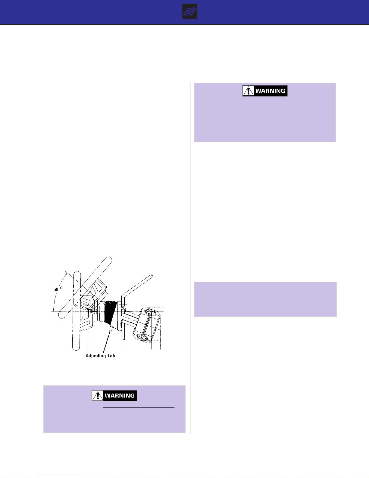
D - 1 GENERAL
STEERING SYSTEMS
Four Winns boats are equipped with rotary-type steering
systems. Tilt and power steering are features which are
available on all Vista models.
A. Rotary Steering
In the rotary system, a rotary drum assembly is mounted
under the dash behind the steering wheel with a one piece
cable running through the boat into the engine compartment. At the transom, the cable turns and is connected
to the engine.
B. Tilt Steering
If equipped with tilt steering, depress the release lever
with your thumb to tilt the steering wheel. See Figure D1.
Be sure to hold the top of the wheel to assist in positioning. Refer to the steering manufacturer’s literature for
additional information.
The tilt mechanism is spring loaded. Due to the
variation in steering wheel offerings, the wheel
may spring up rapidly when depressing the release lever. ALWAYS KEEP ONE HAND ON
THE WHEEL DURING TIL T ADJUSTMENT OR
INJURY MA Y OCCUR.
C. Power Steering
Power steering is standard engine equipment on all Vista
models. It is comprised of an engine mounted pump,
hoses and steering cylinder. Power steering works in
conjunction with the helm and steering cable to move the
transom mount tiller arm and vertical drive more smoothly .
This is a “power assist” system and can greatly reduce
steering effort required. It is not, however, a full power
steering system as is used in automobiles. Some steering tension remains in the system.
On twin engine installations, only the starboard engine is
equipped with a power steering hydraulic assist pump.
Therefore, when operating on a single engine, it is imperative to operate with the starboard engine. If only the
port engine is used, hard steering will result.
Figure D1: Tilt Steering Option
The tilt mechanism should not be adjusted when
the boat is moving. Sudden boat movement may
cause loss of balance resulting in loss of control
and/or injury .
Vista Owners Manual
10/93
NOTICE
DO NOT force the steering unit to either extreme.
This can place undue strain on the unit and can
lead to hydraulic line or seal failure.
Upon commissioning the boat, it is necessary to purge
the system of air. This is performed by your Four Winns
dealer during pre-delivery service. Should steering difficulty increase with time, it is possible additional bleeding
of the system is required. See your Four Winns dealer
for assistance. This and other adjustments on power
steering units are critical and should be performed only
by a qualified service technician.
If the power steering becomes inoperative, steering will
be harder and more effort will be needed to steer the boat.
Check for a broken or loose belt on the power steering
pump. Also, low fluid levels in the power steering pump
reservoir will cause hard steering. If these items are not
the source of the problem, check for equipment or other
items lying on or up against the steering cable at the
Section D
Page 1

back of the boat. The cable must be free and clear to
slide back and forth. Any item blocking free movement of
the cable will result in harder steering and possible damage to the steering cable. If unable to locate or correct
the problem, have the steering cable inspected and lubricated by your Four Winns dealer.
After the first two hours of running time, check
the entire steering system for loose bolts, nuts
and fasteners which could adversely affect steering control.
Propeller torque can also cause the boat to wander (not
follow a straight line) when operated at low speeds. This
condition is normal and can be corrected only by increasing engine rpm. Wind, water currents and play in steering components can cause equivalent effects.
Steering ef fort can vary significantly with engine
acceleration, steering angle, trim angle, and sea
condition. Be prepared for additional steering
loads at all times.
Check the fluid level in the reservoir periodically .
Low power steering fluid levels may increase
steering difficulty .
NOTICE
DO NOT interfere with or restrict steering cable
movement through the last 90m of bend at the
engine. DO NOT use cable retainers, clamps or
tie straps. Using one or all of these could restrict the cable movement near the engine. DO
NOT tie wiring harnesses or other control cables
to the steering cable. Make sure the deck
coaming pads and bulkheads allow for steering
cable movement in all positions of trim.
When storing equipment in the engine compartment, be sure to avoid contact with the steering
cable. Cables may become kinked or damaged
and may increase steering effort.
Additional information on steering operation can be found
in Section Q-9 in this manual and in your Engine Owners
manual.
D - 3 STEERING SYSTEM MAINTENANCE
A periodic inspection of all steering cables, linkage and
helm assemblies should be made. Signs of corrosion,
cracking, loosening of fastenings, excessive wear, or deterioration should be immediately corrected. Failure to
do so could lead to steering system failure and corresponding loss of control.
The helm and cable assembly should be so adjusted that
the steering wheel is centered with the drive or outboard
engine in the straight ahead position. There should be an
equal number of turns to port and starboard from the
straight ahead position. If adjustment becomes necessary , see your Four Winns dealer.
All cables, helm assemblies, and steering connections
should be periodically lubricated with a light, waterproof
grease or as indicated in the manufacturers information
provided with this manual.
D - 2 PROPELLER TORQUE
The propeller rotation of a single engine installation will
exert a directional force on the steering system. This
can cause the steering to be harder in one direction than
the other, and is called propeller torque. If this occurs,
adjust the drive or trim tab (when applicable). Refer to the
Engine Owners manual for information on adjusting the
trim tab.
Vista Owners Manual
10/93
Section D
Page 2
ELECTRICAL SYSTEMS
E - 1 GENERAL
All electrical equipment on the Four Winns Vista models
operates on either 12 volt DC or 120 volt (220 volts on 50
Hertz models) AC electrical power. Dual battery systems are optional on the 238 and 258 Vistas. It is standard on the 278 model. Dockside power (including battery charger) is standard on the 258 and 278 model and
optional on the 238 model. Batteries are located in the
engine compartment.
DO NOT tamper with any electrical connection,
panel or harness, or attempt installation of any
electrical equipment unless thoroughly familiar
with the systems and are experienced in making such installations.
Circuit breakers are installed on the battery switch on the
278 model to protect various system components. The
SHIPs SYSTEMS breaker supplies power to all DC electrical components except the aft and forward bilge pump.
Additional breakers are located in the cabin and helm
circuit breaker panels.
On the 238 and 258 models, Four Winns is installing
automotive-type fuse panels for circuit protection. The aft
fuse panel is located on the port side of the forward engine compartment bulkhead. The refrigerator , forward and
aft bilge pump, and radio are protected by this fuse panel.
All helm and certain cabin equipment are protected by
the helm fuse panel located under the dash.
On all Vista models, circuit breakers and fuses are labeled for amperage and use.
The drawings have been updated recently and may vary
somewhat with earlier model boats.
When installing the battery , proceed as follows:
1. Connect the red (positive) cable running from the engine starter solenoid and ship’s systems cable to
the positive (+) battery terminal. Refer to Figure E1.
2. Connect the black (negative) battery cable running
from the engine block and ship’s systems cable to
the negative (-) battery terminal.
When disconnecting the cables from the battery ,
make sure all switches are off to prevent spark.
NOTICE
DO NOT disconnect the battery while the engine
is running. Alternator and wiring damage could
result.
Monitor the battery’s condition regularly with the V oltmeter gauge in the dash. See Section E-5 and B-8e in this
manual for additional information on the Voltmeter .
E - 3 SINGLE ENGINE - DUAL BA TTERY SYSTEM
A battery selector switch is provided on single engine,
dual battery installations. Dual battery with switch is an
option on the 238 and 258 models and is standard equipment on the 278 model. The battery switch allows DC
power to be used from either one or both batteries. Refer
to Table I for location of the battery switch.
E - 2 SINGLE BATTER Y SYSTEM
(238 & 258 MODELS ONL Y)
A single battery is provided as standard equipment (12
volt DC) on the 238 and 258 Vistas. An ON-OFF battery
switch is installed to disconnect 12 volt equipment from
the battery. Refer to the schematic in the back of the
book labeled:
“238/258 VISTA SINGLE BA TTERY”.
Vista Owners Manual
10/93
Table I: Battery Switch Location
MODEL BATTERY SWITCH LOCA TION
238 Inside Port Storage Tub, Cockpit
258 Inside Port Storage Tub, Cockpit
278 Port Rear Cockpit
Refer to the schematics in the back of this book
labeled:
“238/258 VIST A DUAL BA TTER Y” &
“SINGLE ENGINE-DUAL BA TTERY 278 VIST A”.
Section E
Page 1

A. Installation
When installing dual batteries, proceed as follows:
1. Connect each of the red battery cables leading from
the battery selector switch to the positive (+) terminal on each of the two batteries. See Figure E2.
NOTICE
A label detailing the battery cable connections
is installed in the engine compartment. If disconnecting cables for any reason, be sure to refer to this label for assistance.
NOTICE
Be sure both cables are installed on the positive
(+) battery terminals.
2. Connect the black battery cable and two black/green
stripe leads (see Section E-2, 2 above) to the port
negative (-) battery terminal.
“1” - Turning the switch to position “1” will use battery #1
to power the engine and 12 volt equipment. Battery #2
will be isolated and remain in reserve. Only battery #1
will be charged by the alternator.
“2” - Turning the switch to position “2” will use battery #2.
Except for the automatic bilge pump, battery #1 is isolated and remains in reserve. Only battery #2 will be
charged by the alternator.
“BOTH” - With the battery selector switch in the “BOTH”
position, the batteries are connected in parallel. Both
batteries will be used by the engine and all 12 volt equipment. Both batteries will be charged by the alternator.
The use of one battery at a time is recommended. To
use one battery , move the battery selector switch to either the #1 or #2 position.
Avoid using the “BOTH” position. Use the “BOTH” position only when a single battery is not capable of starting
the engine.
When disconnecting the cables from the battery ,
make sure all switches are off and disconnect
the black negative cable(s) first to prevent spark.
B. Operation
Power to the engine and all 12 volt electrical equipment is
controlled by the battery selector switch. On the 278
model only , separate breakers are provided on the battery selector switch panel to protect the engine, windlass, forward and aft bilge pump and ship systems.
Battery Selector Switch - 238 & 258 Models
Battery selector switch positions for the 238 & 258 models are as follows:
“OFF” - With the battery selector switch in the “OFF”
position, all 12 volt power to the boat is shut off except to
the automatic bilge pump. Always turn the battery selector switch to the OFF position when the boat is unattended for an extended period.
NOTICE
DO NOT turn the battery selector switch to the
“OFF” position while the engine is running. Alternator and wiring damage could result.
Alternate battery usage increases battery longevity . Use
battery #1 for the first day of a cruise and switch to battery #2 on the second day .
Position the battery selector switch to the battery that
has sufficient power to start the engine. After the engine
is running, turn the battery selector switch to the battery
that has the lowest charge. This will allow the alternator
to charge the low battery. Utilizing the battery selector
switch in this manner (instead of using the ALL position)
will supply a greater charge to the battery .
FOR EXAMPLE: If battery #1 is fully charged and battery #2 is in need of a charge, use battery #1 to start the
engine. A fter the engine is running and warmed-up, turn
the battery selector switch to the #2 position. This will
permit the alternator to charge the low, #2 battery .
Monitor the battery condition regularly with the Voltmeter .
See Section E-5 and B-8e in this manual for additional
information.
Battery Selector Switch - 278 Model Only
The battery selector switch positions for the 278 model is
as follows:
“OFF” - With the battery selector switch in the “OFF”
position and the “SHIPS SYSTEMS” circuit breaker in
the “off” position, all 12 volt power to the boat is shut off
Vista Owners Manual
10/93
Section E
Page 2

except to the automatic bilge pumps. Always turn the
battery selector switch to the “OFF” position when the
boat is unattended for an extended period.
NOTICE
Twelve volt power to the cabin p anel is supplied
by the “SHIPS SYSTEMS” circuit breaker on the
battery selector panel. This must be turned on
to operate any 12 volt accessories on the cabin
panel. The bilge pumps receive power from the
ships system battery and remain on at all time
regardless of battery selector or ship systems
switch position.
NOTICE
DO NOT turn the battery selector switch to the
“OFF” position while the engine is running. Alternator and wiring damage could result.
“ON” - Turning the switch to position “ON” will use battery
#1 to power the engine and 12 volt engine related equipment. Battery #2 will be isolated and remain in reserve.
Only battery #1 will be charged by the alternator.
NOTICE
The 278 Vista may include the installation of an
isolator as an option. If installed, both batteries
will be charged at all times.
“SHIP SYSTEMS” - Turning the switch to position “SHIPS
SYSTEMS” will use battery #2. Battery #1 is isolated
and remains in reserve. Only battery #2 will be charged
by the alternator.
C. Battery Charger
The battery charger is standard equipment on the 258
and 278 models and is optional on the 238 model. The
batteries in a dual battery system may be charged by a
battery charger/converter when the boat is connected to
dockside power. Refer to T able II for Battery Charger location.
Table II: Battery Charger Location
MODEL BATTERY CHARGER LOCA TION
238 Port Engine Compartment
258 Port Engine Compartment
278 Port Forward Storage Tub, Cockpit
Additional information on the battery charger can be found
in Section E-8b 120 Volt AC Equipment in this manual
and refer to the manufacturer’s literature included with
this manual.
E - 4 DUAL ENGINE - DUAL BATTER Y SYSTEM
(278 MODEL ONL Y)
A battery selector switch is installed on dual engine, dual
battery installations. This allows DC power to be used
from either one or both batteries. Refer to the schematic
in the back of the book labeled:
“TWIN ENGINE-DUAL BA TTERY 278 VIST A”.
A. Installation
“BOTH” - With the battery selector switch in the “BOTH”
position, the batteries are connected in parallel. Both
batteries will be used by the engine and all 12 volt equipment. Both batteries will be charged by the alternator.
The battery switch operation is very similar to the 238/
258 installation. However , if an isolator is installed, it will
not be necessary to alternate between “ON” or “SHIPS
SYSTEMS” to charge the batteries. Both batteries will
be charged at the same time.
Monitor the battery condition regularly with the Voltmeter .
See Section E-5 and B-8e in this manual for additional
information.
Vista Owners Manual
10/93
Installation of cables is the same as the section on Single
Engine-Dual Battery System above except the ground
cables. An additional black cable is connected to the
other engine.
NOTICE
A label detailing the battery cable connections
is installed in the engine compartment. If disconnecting cables for any reason, be sure to refer to this label for assistance.
B. Operation
Power to the engines and all 12 volt electrical equipment
is controlled at the battery selector panel. On the 278
model, separate breakers are provided on the battery selector switch panel to protect the engine, windlass, forward and aft bilge pump and ship systems.
Section E
Page 3
 Loading...