

Fourgroup Easy, EcoEasy series Use And Programming Handbook
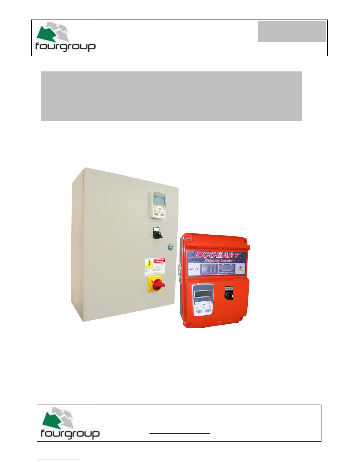
USE AND PROGRAMMING HANDBOOK
FREQUENCY INVERTER FOR AN ELECTRIC PUMP
PR .T : FG005912
Date : 11/01/10
Rev . 01
Via Enrico Fermi, 8 - 35020 - Polverara - PD - ITALY
Tel. +39.049.9772407 Fax. +39.049.9772289
www.fourgroup.it
E-mail : info@fourgroup.it

2
The following symbols, accompanied by the words: “Danger”, “Warning”,
indicate the potential hazard resulting from failure to observe the associated
warning, as specified below:
Failure to observe this warning may result in electric
shock
Failure to observe this warning may cause personal
injury and/or damage to property
Failure to observe this warning may cause damage
to the pump, the unit or the system
- CAUTION:
Make sure the pumps are fully primed before you start them.
- CAUTION:
The control panel must be connected by a qualified electrician in compliance with the
electrical regulations in force.
- CAUTION:
The electric pump or the motor and the panel must be connected to an efficient
grounding system in compliance with the electrical regulations locally in force.
- CAUTION:
Ground the unit before carrying out any other operation.
- CAUTION:
The electric pump or the motor can start up automatically.
- CAUTION:
As a general rule, always disconnect the power supply before proceeding to carry out
any operation on the electrical or mechanical components of the unit or system.
1. WARNINGS
DANGER
RISK OF ELECTRI C
SHOCK
DANGER
WARNING
1. WARNINGS
3
The purpose of this manual is to provide the necessary information for the proper
installation, use and maintenance of
SC/1-TA. The user should read this manual before
operating the unit. Improper use may cause damage to the machine and lead to the
forfeiture of the warranty coverage. Always specify the model identification code and the
construction number when requesting technical information or spare parts from our Sales
and Service department. The instruction and warnings given below concern the standard
version; refer to the sale contract documentation for modifications and special version
characteristics. For instructions, situations and events no t considered in this manual or in
the sale documents, please contact our customer service.
Our units must be installed in sheltered, well-ventilated, non-hazardous environments and
must be used at a maximum temperature of +40°C and minimum of -5°C.
DANGER
WARNING
The panel must be handled with care, as falls and knocks can cause damage without any
visible external signs.
If for any reason the unit is not installed and starter immediately after it has reached its
destination it must be stored properly. The external packaging and the separately packed
accessories must remain intact, and the whole must be protected from the weather,
especially from freezing temperatures, and from any knocks or falls.
PRELIMINARY INSPECTION: after you have removed the external packaging, visually
inspect the control panel to make sure it has suffered no damage during shipping.
If any damage is visible, inform a FOURGROUP dealer as soon as possible, no later then
five days from the delivery date.
FOURGROUP S.r.l. shall not be liable for any damage caused or suffered by the
unit as a result of its unauthorised or improper use.
2. OVERVIEW
3. HANDLING
4
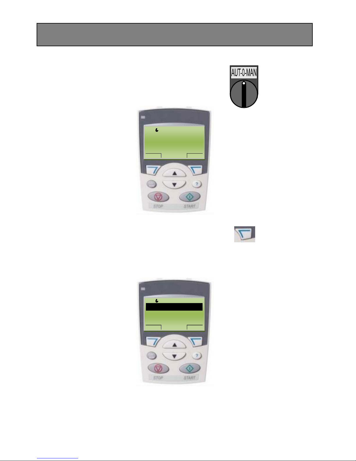
-Position the AUT-0-MAN selector switch on “0” and the
keypad should display
-Enter the programming menu and press “MENU”
-The following will be displayed on the keypad:
REM
0.0 Hz
DIR MENU
0.0 Hz
0.0 A
0.0 bar
REM
MAIN MENU---------1
EXIT
ENTER
PARAMETERS-----
ASSISTANTS
CHANGED PAR
4. PROGRAMMING THE ABB-ACS INVERTER WITH THE
PANEL ASSISTANT
5
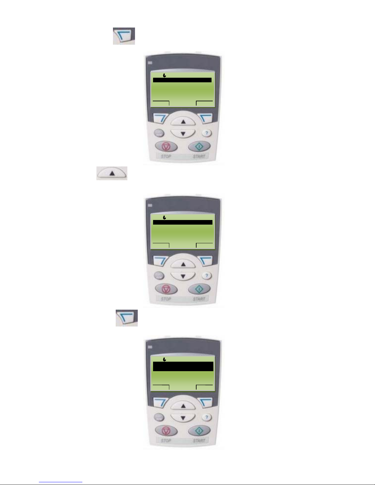
-Press “ENTER” and the keypad should display:
-With the up
arrow select the family
“-99 START UP DATA-“ the keypad should display:
-Press “SELECT” and the keypad should display:
REM
PAR GRUOPS--------01
EXIT SEL
01 OPERATING DATA_ _____
03 FB ACTUAL SIGNALS
04 FAULT HISTORY
10 START/STOP/DIR
11 REFERENCE SELECT
REM
PAR GRUOPS--------99
EXIT SEL
99 START-UP DATA ----
01 OPERATING DATA
03 FB ACTUAL SIGNALS
04 FAULT HISTORY
10 START/STOP/DIR
REM
PARAMETERS-------
EXIT EDIT
9901 LANGUAGE---------//…/----
---------------ENGLISH-/////////-------9902 APPLIC MACRO
9903 MOTOR TYPE
9904 MOTOR CTRL MODE
6
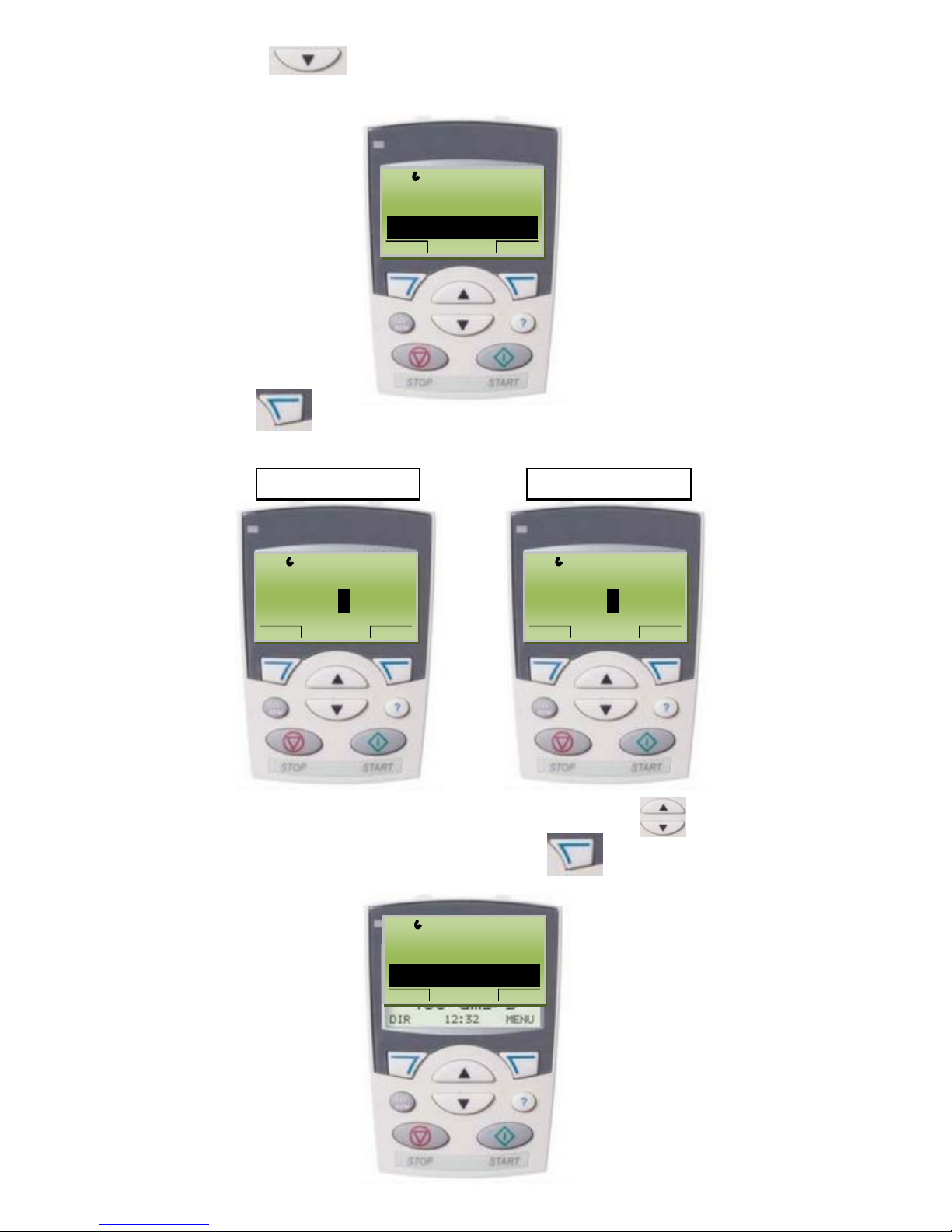
-With the down arrow select the parameter
“9905 MOTOR NOMINAL VOLTAGE“ and the keypad should display:
-Press “EDIT” and check that the correct power voltage (Volt) of
the motor appears on the keypad.
- To change the value press the up or down arrows
Set the required value and press “SAVE”
and the keypad should display:
Ex. motor 230V Ex. motor 400V
REM
PARAMETERS-------
EXIT EDIT
9902 APPLIC MACRO
9903 MOTOR TYPE
9904 MOTOR CTRL MODE
9905 MOTOR NOM VOLT ---
-------------- … … V… .… .---- ---
REM
PAR EDIT--------------
CANCEL SAVE
9905 MOTOR NOM VOLT
230 V
REM
CANCEL SAVE
9905 MOTOR NOM VOLT
400 V
REM
PARAMETERS-------
EXIT
EDIT
9902 APPLIC MACRO
9903 MOTOR TYPE
9904 MOTOR CTRL MODE
9905 MOTOR NOM VOLT ---
----- .230 / 400 V… .….---- ---
PAR EDIT--------------

7
-With the down arrow select the parameter
“9906 MOTOR NOMINAL CURRENT“ and the keypad should display:
-Press “EDIT” and check that the correct absorption current (A) of
the motor appears on the keypad.
Example 4A motor:
- To change the value press the up or down arrows
Set the required value and press “SAVE” and the keypad
should display:
REM
PARAMETERS-------
EXIT EDIT
9903 MOTOR TYPE
9904 MOTOR CTRL MODE
9905 MOTOR NOM VOLT
9906 MOTOR NOM CURR .-- .
………… . .… A ….…
REM
CANCEL
SAVE
9906 MOTOR NOM CURR
4.0 A
PAR EDIT--------------
REM
PARAMETERS-------
EXIT EDIT
9903 MOTOR TYPE
9904 MOTOR CTRL MODE
9905 MOTOR NOM VOLT
9906 MOTOR NOM CURR . .
------- 4.0 A //////////…
 Loading...