

Four-Faith F-PM100 User Manual
F-PM100 Multifunctional Power Meter User Manual
F-PM100
Multifunctional Power
Meter User Manual
Product Version
Page
V1.0
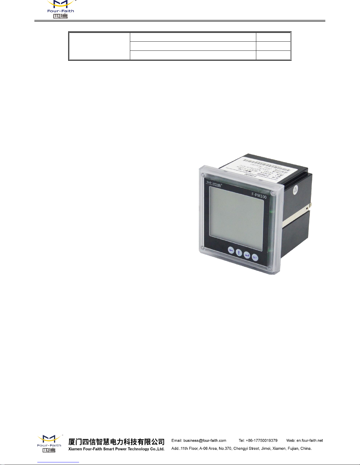
Product Name:F-PM100
Total:
F-PM100
Multifunctional Power Meter
For Power Distribution System
User Manual
Version 1.0

F-PM100 Multifunctional Power Meter User Manual
1. Product Introduction
Multi-function power meter, a multi-function intelligent power meter with full power acquisition,
programmable measurement, display, RS485 digital communication and switch input, relay output,
it can complete three-phase electrical measurement (includes three-phase voltage, three-phase
current, active power, reactive power, apparent power, power factor, frequency, harmonics,
multi-rates, demand, SOE event records, etc.), four quadrant energy metering, data display,
acquisition and transmission, therefore it can be widely used in substation automation, distribution
automation, intelligent building, internal energy measurement, management, assessment for
company. Using the special measurement chip, the power meter could achieve large-screen LCD
liquid crystal display and RS-485 communication interface, communication protocol is the standard
MODBUS-RTU.
2. Technical Parameters and Indicators
Working Power Supply
220VAC±10% or 85~265VAC/DC
Working Temperature
Storage Temperature
Operating and storage
Humidity
Insulation Grade
Operating Frequency
Product Life
Size
Display Panel:96mm×96mm×12mm(W×H×D)
Main Unit:96mm×96mm×75mm(W×H×D)
Weight
Protection Grade
Input characteristics
Input Characteristics
Communication
Range of the Power Meter Address:1 254
Note:Indicates that the function parameter is related to the order type.

F-PM100 Multifunctional Power Meter User Manual
Parameter
Accuracy
Measuring range
Voltage
0.2
0 999,999V
Current
0.2
0 49,999A
Power Factor
0.5
-1.0<|CosΦ|<+1.0
Active Power
0.5
Single-Phase:0 100MW
Total:0 300MW
Reactive Power
0.5
Single-Phase:0 100Mvar
Total:0 300Mvar
Apparent power
0.5
Single-Phase:0 100MVA
Total:0 300MVA
Electrical Degree
0.5
0 9999999.9kWh/kvarh
Frequency
0.1Hz
45 65Hz
3. Installation and Wiring
Drill a hole of 91 * 91mm on the switch cabinet panel.
Take out the Power Meter, release the the fixed bolts on both sides of Power Meter , remove
the metal fixed bracket.
Insert the Power Meter into the mounting hole from the front panel.
Insert the metal fixed bracket and screw the bolts to fix the power meter.
3.2 Definition of the Terminal block on Power Meter
Number
Code
Definition
1
Ia*
A Phase current line
2
Ia
A Phase current outlet
3
Ib*
B Phase current line
4
Ib
B Phase current outlet
5
Ic*
C Phase current line
6
Ic
C Phase current outlet
7
Ua
A Phase voltage
8
Ub
B Phase voltage
9
Uc
C Phase voltage
10
Un
Neutral line
11*
A
RS485 Communication Interface
Positive
12*
B
RS485 Communication Interface Negative
13*
COM
Binary Input of the Public Terminal
14*
DI1
Binary Input 1
15*
DI2
Binary Input 2
16*
DI3
Binary Input 3
F-PM100 Multifunctional Power Meter User Manual
Remark: Indicates that the terminal function is related to the order type.
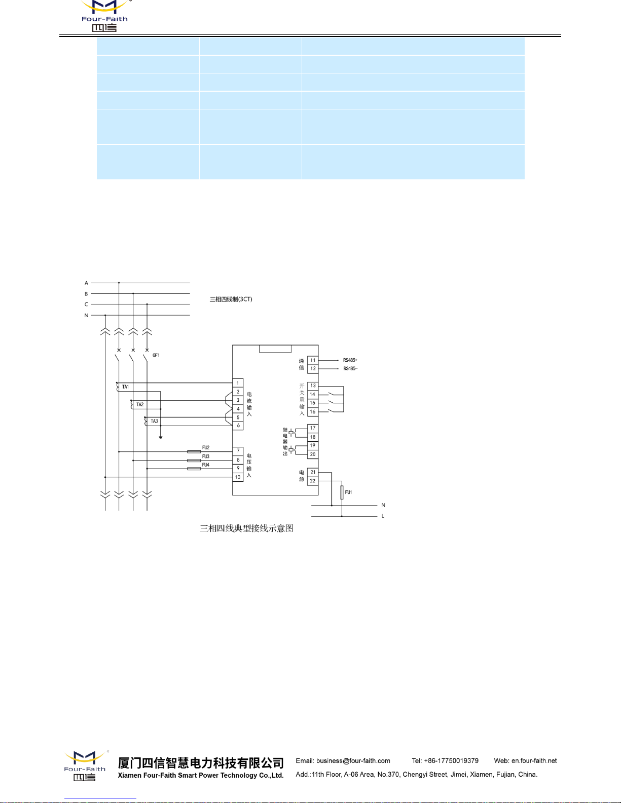
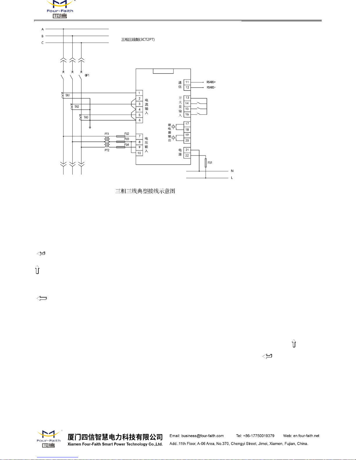
3.3 Typical Wiring Diagram of the Power Meter
Wiring Diagram of Three Phrase Four Wire:
Wiring Diagram of Three Phrase Three Wire:
17*
R11
Relay 1 Output
18*
R12
Relay 1 Output
19*
R21
Relay 2 Output
20*
R22
Relay 2 Output
21
N/-
AC power supply
220V Zero Line
22
L/+
AC power supply
220V live wire
F-PM100 Multifunctional Power Meter User Manual
4. Power Meter Parameter Setting
4.1 Key Functions in Setup Mode:
: When the cursor is flashing, select and confirm the function (Enter key);
: When the cursor is flashing, modify the configuration; When the cursor is flashing, switch the
parameter page (up key);
: When the cursor is flashing, turn the cursor on the same page to the left (press the left
button).
4.2 Description of the Parameter Setting
Note: Press "SET" key to enter the parameter setting interface, you can press the " " key to
directly view the current parameters of the Power Meter. When you press the " " key to view the
Power Meter parameters and it will pop up "need pswd" to indicate the need for a password to set
up.
 Loading...