

Four-Faith F8913D, F8913D-N-NS User Manual

F8913D User Manual
Xiamen Four-Faith Communication Technology Co.,Ltd. Page 1 of 99
Add: J1-J3,3rdFloor,No.44,GuanRiRoad,SoftWare Park,XiaMen .China
http://www.fourfaith.com Tel: +86 592-6300326 6300325 6300324 Fax:+86 592-5912735
F8913D User Manual
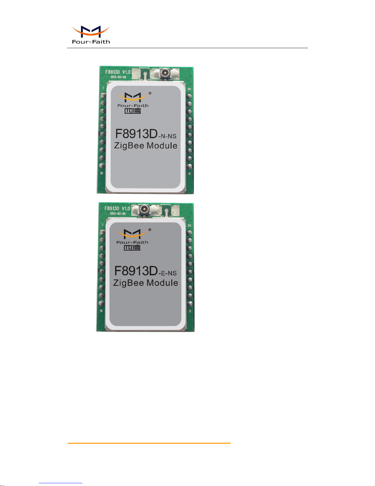
The user manual is suitable for the following model:
Model
Product Type
F8913D-N-NS
Without PA,DIP
F8913D-E-NS
With PA,DIP
Xiamen Four-Faith Communication Technology Co., Ltd.
Add:J1-J3,3rd Floor,No.44,GuanRi Road,SoftWare Park,XiaMen,China
Zip Code: 361008
Tel: +86 592-6300326,6300325,6300324
Fax: +86 592-5912735
http://www.fourfaith.com
F8913D
User Manual
Documentation No.
Product Version
Page
V1.10
Product Name:F8913D
Total:99

F8913D User Manual
Xiamen Four-Faith Communication Technology Co.,Ltd. Page 2 of 99
Add: J1-J3,3rdFloor,No.44,GuanRiRoad,SoftWare Park,XiaMen .China
http://www.fourfaith.com Tel: +86 592-6300326 6300325 6300324 Fax:+86 592-5912735
Files Revised Record
Date
Version
Remark
Author
2013-4-15
V1.00
Draft
Tady Chen
2013-07-04
V1.10
Add API configure command description,
and route sleep mode configure.
Tady Chen

F8913D User Manual
Xiamen Four-Faith Communication Technology Co.,Ltd. Page 3 of 99
Add: J1-J3,3rdFloor,No.44,GuanRiRoad,SoftWare Park,XiaMen .China
http://www.fourfaith.com Tel: +86 592-6300326 6300325 6300324 Fax:+86 592-5912735
Copyright Notice
All contents in the files are protected by copyright law, and all copyrights are reserved by
Xiamen Four-Faith Communication Technology Co., Ltd. Without written permission, all
commercial use of the files from Four-Faith are forbidden, such as copy, distribute, reproduce the
files, etc., but non-commercial purpose, downloaded or printed by individual (all files shall be not
revised, and the copyright and other proprietorship notice shall be reserved) are welcome.
Trademark Notice
Four-Faith、四信、 、 、 are all registered trademarks of Xiamen
Four-Faith Communication Technology Co., Ltd., illegal use of the name of Four-Faith,
trademarks and other marks of Four-Faith is forbidden, unless written permission is authorized in
advance.
F8913D User Manual
Xiamen Four-Faith Communication Technology Co.,Ltd. Page 4 of 99
Add: J1-J3,3rdFloor,No.44,GuanRiRoad,SoftWare Park,XiaMen .China
http://www.fourfaith.com Tel: +86 592-6300326 6300325 6300324 Fax:+86 592-5912735

F8913D User Manual
Xiamen Four-Faith Communication Technology Co.,Ltd. Page 5 of 99
Add: J1-J3,3rdFloor,No.44,GuanRiRoad,SoftWare Park,XiaMen .China
http://www.fourfaith.com Tel: +86 592-6300326 6300325 6300324 Fax:+86 592-5912735
CCoonntteennttss
CCoonntteenntts
s ............................................................................................................................................ 5
Chapter 1 Brief Introduction of Product ........................................................................................... 9
1.1 Overview ................................................................................................................. 9
1.2 Features and Benefits ............................................................................................ 9
1.3 Specification ......................................................................................................... 10
Chapter 2 Module Interface ............................................................................................................ 13
2.1 Module Signal Definition....................................................................................... 13
2.2 UART .................................................................................................................... 14
2.3 GPIO Specification ............................................................................................... 15
2.4 Antenna Interface ................................................................................................. 16
2.5 Antenna Installation .............................................................................................. 17
2.6 Firmware Performance Specifications ................................................................. 18
2.7 Absolute Maximum Ratings .................................................................................. 18
Chapter 3 Communication Interface Operation .............................................................................. 19
3.1 UART .................................................................................................................... 19
3.1.1 UART signal description ........................................................................................ 19
3.1.2 UART connections ................................................................................................. 19
3.1.3 UART Characteristics ............................................................................................ 20
3.2 Analog and Digital I/O ........................................................................................... 21
3.2.1 Signal Definition .................................................................................................... 21
3.2.2 Function Description .............................................................................................. 21
Chapter 4 Parameter Configuration ................................................................................................ 22
4.1 Zigbee Description ............................................................................................... 22
4.1.1 Device Type Description ........................................................................................ 22
4.1.1.1 Coordinator ................................................................................................. 22
4.1.1.2 Router .......................................................................................................... 22
4.1.1.3 End Device .................................................................................................. 22
4.1.2 ZigBee Network Description ................................................................................. 23
4.1.2.1 Form a ZigBee Network Procedure............................................................. 23
4.1.2.2 Physical Channel ......................................................................................... 23
4.1.2.3 PAN ID ........................................................................................................ 23
4.1.2.4 Node address ............................................................................................... 23
4.2 Configuration Connection ..................................................................................... 24
4.3 Configuration Introduction .................................................................................... 24
4.3.1 Run the configure Tool: ZigbeeConfigure.exe ....................................................... 25
4.4 Modes of Operation .............................................................................................. 26
4.4.1 Transparent mode ................................................................................................... 26
4.4.2 AT command mode................................................................................................. 27
4.4.2.1 Set device PAN ID: AT+PID ....................................................................... 27
4.4.2.2 Query device current PAN ID: AT+PCD..................................................... 28
4.4.2.3 Set device physical channel: AT+CHA ....................................................... 28

F8913D User Manual
Xiamen Four-Faith Communication Technology Co.,Ltd. Page 6 of 99
Add: J1-J3,3rdFloor,No.44,GuanRiRoad,SoftWare Park,XiaMen .China
http://www.fourfaith.com Tel: +86 592-6300326 6300325 6300324 Fax:+86 592-5912735
4.4.2.4 Query device MAC address: AT+MID ........................................................ 28
4.4.2.5 Set device type: AT+TYP ............................................................................ 29
4.4.2.6 Set device node address: AT+NID .............................................................. 29
4.5.2.7 Query device current node address : AT+NCD ........................................... 29
4.4.2.8 Set decice transparent address: AT+TID ..................................................... 30
4.4.2.9 Set device serial........................................................................................... 30
4.4.2.9.1 Set device serial baudrate: AT+IPR .................................................. 30
4.4.2.9.2 Set device serial parity: AT+PAR ..................................................... 31
4.4.2.9.3 Set device serial stop bit: AT+STO .................................................. 31
4.4.2.9.4 Set device serial port hardware flow control:AT+UFC.................... 32
4.4.2.10 Set device AT command echo: AT+ECH .................................................. 32
4.4.2.11 Set device to get acknowledge: AT+ACK ................................................. 33
4.4.2.12 Set device debug level: AT+DBL .............................................................. 33
4.4.2.13 Set device whether auto starts network when powered:AT+AST ............. 34
4.4.2.14 Start devcie network : AT+STA................................................................. 34
4.4.2.15 Set device whether RF data output the serial port: AT+PRF ..................... 34
4.4.2.16 Query device softwarte version : AT+VER ............................................... 35
4.4.2.17 Query all devices state in the same network: AT+NWS............................ 35
4.4.2.18 Query a device node address : AT+QNA .................................................. 36
4.4.2.19 Query a device MAC address : AT+QMA ................................................ 36
4.4.2.20 Query device net state: AT+SNS ............................................................... 36
4.4.2.21 Send data (HEX mode): AT+TXH ............................................................ 37
4.4.2.22 Send data (ASCII mode) : AT+TXA ......................................................... 37
4.4.2.23 Receive RF data ........................................................................................ 37
4.4.2.24 Device IO pins command .......................................................................... 38
4.5.2.24.1 Set IO pin mode: AT+DMn ............................................................ 38
4.4.2.24.2 Set IO pin data acquisition time interval : AT+DTn ....................... 39
4.4.2.24.3 Set IO pluse input count value: AT+DSn ....................................... 39
4.4.2.24.4 Query IO pin value : AT+DVn ....................................................... 40
4.4.2.24.5 Query a device IO pin value: AT+NVn .......................................... 40
4.4.2.24.6 Remote set a device IO pin mode : AT+NSn .................................. 40
4.4.2.25 Set device sleep mode:AT+SLE ............................................................... 41
4.4.2.26 Set device sleep time:AT+STC ................................................................. 41
4.4.2.27 Set device wake time:AT+WTC ............................................................... 42
4.4.2.28 Set serial data interval:AT+ITV ................................................................ 42
4.4.2.29 Query device bootload version :AT+BTL................................................. 42
4.4.2.30 Set device work mode:AT+MOD .......................................................... 43
4.4.2.31 Set data route method:AT+SKP ............................................................. 43
4.4.2.32 Set API mode whether echo data send state:AT+MTC .......................... 43
4.4.2.33 Other execute command ............................................................................ 44
4.4.3 API mode................................................................................................................ 45
4.4.3.1 Device send data ......................................................................................... 46
4.4.3.2 Device receive the RF data.......................................................................... 46

F8913D User Manual
Xiamen Four-Faith Communication Technology Co.,Ltd. Page 7 of 99
Add: J1-J3,3rdFloor,No.44,GuanRiRoad,SoftWare Park,XiaMen .China
http://www.fourfaith.com Tel: +86 592-6300326 6300325 6300324 Fax:+86 592-5912735
4.4.3.3 Remote query a device IO value ................................................................. 47
4.4.3.4 Remote set a device IO mode ...................................................................... 48
4.4.3.5 Query all devices state in the same network ............................................... 49
4.4.3.6 Query a device MAC address...................................................................... 50
4.4.3.7 Query a device node address ....................................................................... 51
4.4.3.8 Set the node current operating mode ........................................................... 52
4.4.3.9 Set device parameter ................................................................................... 53
4.4.3.9.1 Set device work mode ...................................................................... 53
4.4.3.9.2 Set device physical channel .............................................................. 54
4.4.3.9.3 Set device type ................................................................................. 55
4.4.3.9.4 Set device PAN ID ........................................................................... 56
4.4.3.9.5 Set device node address .................................................................... 57
4.4.3.9.6 Set device serial port baudrate.......................................................... 58
4.4.3.9.7 Set device serial port parity .............................................................. 59
4.4.3.9.8 Set device serial port stop bit ........................................................... 60
4.4.3.9.9 Set device serial port hardware flow control .................................... 61
4.4.3.9.10 Set device serial port data interval.................................................. 62
4.4.3.9.11 Set device debug level .................................................................... 63
4.4.3.9.12 Set device sleep mode .................................................................... 64
4.4.3.9.13 Set device wake time ...................................................................... 65
4.4.3.9.14 Set device sleep time ...................................................................... 66
4.4.3.9.15 Set D0 pin mode ............................................................................. 67
4.4.3.9.16 Set D0 pin data acquisition time interval ....................................... 68
4.4.3.9.17 Query D0 pin value ........................................................................ 69
4.4.3.9.18 Set D1 pin mode ............................................................................. 70
4.4.3.9.19 Set D1 pin data acquisition time interval ....................................... 71
4.4.3.9.20 Query D1 pin value ........................................................................ 72
4.4.3.9.21 Set D2 pin mode ............................................................................. 73
4.4.3.9.22 Set D2 pin data acquisition time interval ....................................... 74
4.4.3.9.23 Query D2 pin value ........................................................................ 75
4.4.3.9.24 Set D3 pin mode ............................................................................. 76
4.4.3.9.25 Set D3 pin data acquisition time interval ....................................... 77
4.4.3.9.26 Query D3 pin value ........................................................................ 78
4.4.3.9.27 Set D4 pin mode ............................................................................. 79
4.4.3.9.28 Set D4 pin data acquisition time interval ....................................... 80
4.4.3.9.29 Query D4 pin value ........................................................................ 81
4.4.3.9.30 Query device current PAN ID ........................................................ 82
4.4.3.9.31 Query device current node address................................................. 82
4.4.3.9.32 Query device current network state ................................................ 83
4.4.3.9.33 Set device whether auto starts network when powered .................. 84
4.4.3.9.34 Set device whether RF data output the serial port .......................... 85
4.4.3.9.35 Set data route method ..................................................................... 86
4.4.3.9.36 Set device to get acknowledge ....................................................... 87

F8913D User Manual
Xiamen Four-Faith Communication Technology Co.,Ltd. Page 8 of 99
Add: J1-J3,3rdFloor,No.44,GuanRiRoad,SoftWare Park,XiaMen .China
http://www.fourfaith.com Tel: +86 592-6300326 6300325 6300324 Fax:+86 592-5912735
4.4.3.9.37 Set API mode whether echo data send state ................................... 88
4.4.3.9.38 Set D3 pluse input count value ....................................................... 89
4.4.3.9.39 Set D4 pluse input count value ....................................................... 89
4.4.3.9.40 Set device transparent address ........................................................ 90
4.4.3.10 Device parameter execute command ......................................................... 91
4.4.3.10.1 Parameter save command ............................................................... 91
4.4.3.10.2 Factory command ........................................................................... 91
4.4.3.10.3 Restart device ................................................................................. 92
4.4.3.10.4 Start device network ....................................................................... 92
4.5 Device sleep mode configuration description ........................................................... 93
4.5.1 Timer sleep ..................................................................................................... 93
4.5.2 Deep sleep ...................................................................................................... 93
Chapter 5 Reference Circuit ............................................................................................................ 94
5.1 Power.................................................................................................................... 94
5.2 Communication..................................................................................................... 94
5.3 Reset .................................................................................................................... 95
5.4 Digital I/O .............................................................................................................. 96
5.5 ADC Sampling Circuit ........................................................................................... 96
Chapter 6 Dimension and solder ..................................................................................................... 97
6.1 Outline Dimension ................................................................................................ 97
6.2 PCB Footprint ....................................................................................................... 97
6.3 Re-flow Temperature Specification ...................................................................... 98
Chapter 7 Ordering Information...................................................................................................... 99
F8913D User Manual
Xiamen Four-Faith Communication Technology Co.,Ltd. Page 9 of 99
Add: J1-J3,3rdFloor,No.44,GuanRiRoad,SoftWare Park,XiaMen .China
http://www.fourfaith.com Tel: +86 592-6300326 6300325 6300324 Fax:+86 592-5912735
Chapter 1 Brief Introduction of Product
1.1 Overview
F8913D ZigBee terminal is a kind of data terminal device that provides data transfer function
by ZigBee network.
The product uses high-performance industrial-grade ZigBee solution, support transparent
data transmission function; low power consumption design, the lowest working current can less
than 1uA; supply 5 I/O channels, compatible 5 GPIO channels, 3 analog inputs and 2 pulse input
counters.
It has been widely used on M2M fields, such as intelligent transportation, smart grid,
industrial automation, telemetry, finance, POS, water supply, environment protection, post,
weather, and so on.
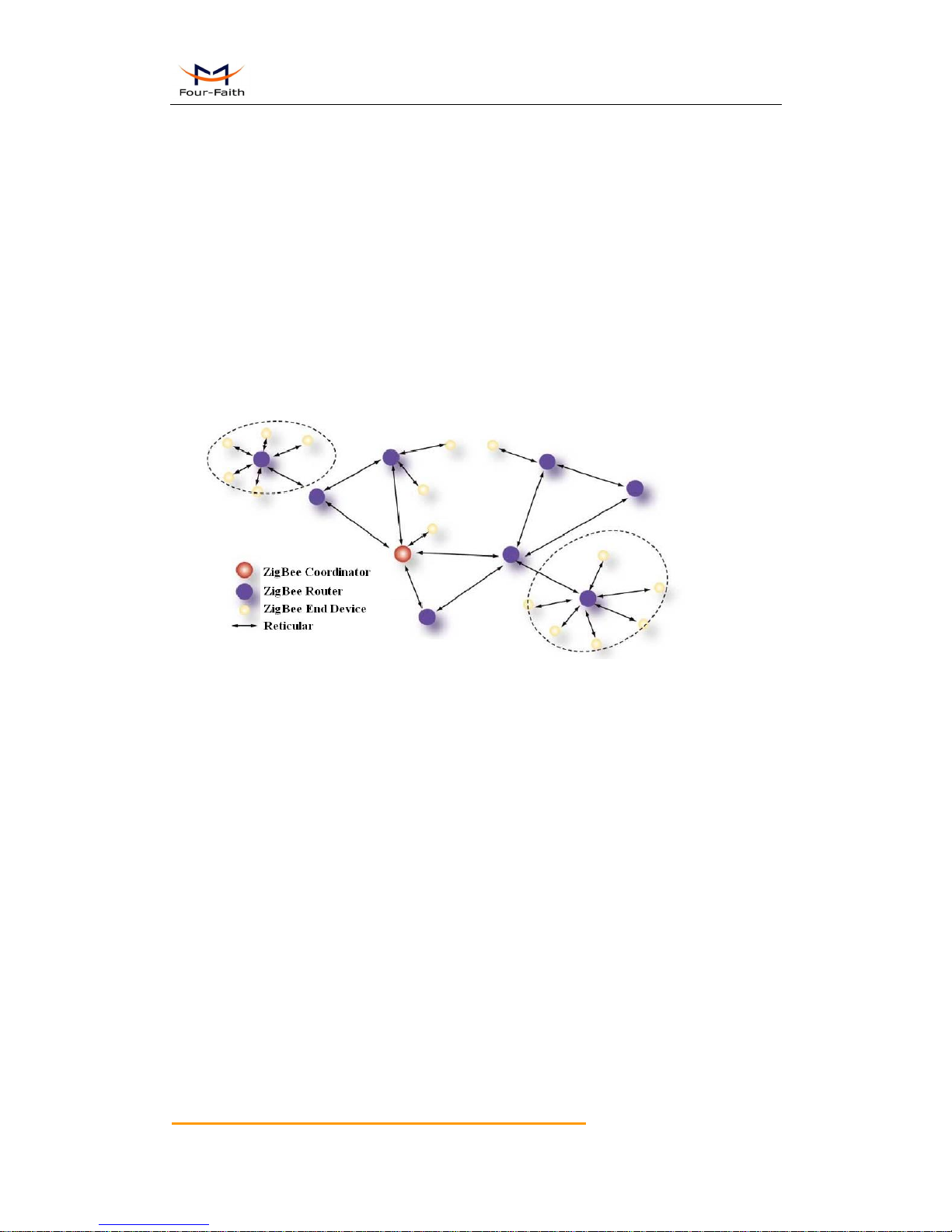
Figure 1-1 Application Topology
1.2 Features and Benefits
Design for Industrial Application
High-powered industrial ZigBee chip
Low power consumption design, support multi-sleep and trigger modes to reduce the power
dissipation farthest
Support UART
Power range: DC 2.0~3.6V
Stability and Reliability
Support hardware and software WDT
Support auto recovery mechanism
Standard and Convenience
Adopt a miniature package, support 2.0mm spacing stamp hole for SMT and 2.0mm spacing
through-hole pins simultaneous
Support intellectual mode, enter into communication state automatically when powered,
support several work modes.
Convenient configuration and maintenance interface
Support for serial software upgrades

F8913D User Manual
Xiamen Four-Faith Communication Technology Co.,Ltd. Page 10 of 99
Add: J1-J3,3rdFloor,No.44,GuanRiRoad,SoftWare Park,XiaMen .China
http://www.fourfaith.com Tel: +86 592-6300326 6300325 6300324 Fax:+86 592-5912735
High-performance
Support ZigBee wireless data transmission
Support repeater and end-device function
Support Point-to-Point, Point-to-Multipoint, Peer-to -Peer and Mesh network
Support 65000 nodes
Support center node, router node and terminal node
Support broadcast and target address transfer
Wide communication range
Supply 5 I/O channels, 5 GPIO output channels, compatible 3 analog inputs and 2 pulse input
counters.
1.3 Specification
F8913D Model Sheet
Model
Content
F8913D-N-NS
Without PA,DIP
F8913D-E-NS
With PA,DIP
ZigBee Specification
Item
Content
MCU
Industrial ZigBee Platform
Communication Protocol
and Band
IEEE 802.15.4
ISM2.4~2.5GHz
Indoor/Urban Range
30m
90m(With PA)
Outdoor/RF Line-of-Sight
Range
500m
2000m(With PA)
Transmit Power
2.82 mw (+4.5dBm)
100 mw (+20dBm) (With PA)
RF Data Rate
250Kbps
Receiver Sensitivity
-97dBm
-103dBm (With PA)
Network Topologies
Point-to-Point, Point-to-Multipoint, Peer-to-Peer and Mesh
Channels
11 to 26
Max Serial Buffer Size
300 Bytes

F8913D User Manual
Xiamen Four-Faith Communication Technology Co.,Ltd. Page 11 of 99
Add: J1-J3,3rdFloor,No.44,GuanRiRoad,SoftWare Park,XiaMen .China
http://www.fourfaith.com Tel: +86 592-6300326 6300325 6300324 Fax:+86 592-5912735
Interface Type
Item
Content
UART
Data bits: 8
Stop bits: 1, 2
Checksum: none,odd,even
Baudrate: 300, 600, 1200, 2400, 4800, 9600, 19200, 38400,57600,
115200 bps
Antenna connector
U.FL RF connector, impedance 50 ohm
Package
Support 2.0mm spacing through-hole pins simultaneous
Power Input
Item
Content
Recommended Power
DC 3.3V/0.1A
Power Range
DC 2.0~3.6V
Power Consumption
Working States
Power Consumption
F8913D-N-NS
Coordinator
Idle Mode
28.3~28.4mA@3.3VDC
RX Mode
27.5~27.8mA@3.3VDC
TX Mode
28.8~29.1mA@3.3VDC
Router
Idle Mode
28.2~28.4mA@3.3VDC
RX Mode
27.5~27.8mA@3.3VDC
TX Mode
28.9~29.1mA@3.3VDC
Timing wake up
1.1~1.2uA@3.3VDC
Deep Sleep
0.3~0.4 uA@3.3VDC
EndDevice
Idle Mode
8.6~8.9mA@3.3VDC
RX Mode
10.8~11.5mA@3.3VDC
TX Mode
14.4~15.2mA@3.3VDC
Timing wake up
1.1~1.2uA@3.3VDC
Deep Sleep
0.3~0.4 uA@3.3VDC
F8913D-E-NS
Coordinator
Idle Mode
30.5~31.5mA@3.3VDC
RX Mode
32.2~33.2mA@3.3VDC
TX Mode
41.2~42.4mA@3.3VDC
Router
Idle Mode
30.4~31.5mA@3.3VDC
RX Mode
32.4~33.2mA@3.3VDC
TX Mode
41.2~42.5mA@3.3VDC
Timing wake up
1.2~1.3uA@3.3VDC
Deep Sleep
0.4~0.5 uA@3.3VDC
EndDevice
Idle Mode
9.0~9.6mA@3.3VDC
RX Mode
13.1~14.3mA@3.3VDC
TX Mode
24.5~26.5mA@3.3VDC
Timing wake up
1.2~1.3uA@3.3VDC
Deep Sleep
0.4~0.5 uA@3.3VDC

F8913D User Manual
Xiamen Four-Faith Communication Technology Co.,Ltd. Page 12 of 99
Add: J1-J3,3rdFloor,No.44,GuanRiRoad,SoftWare Park,XiaMen .China
http://www.fourfaith.com Tel: +86 592-6300326 6300325 6300324 Fax:+86 592-5912735
Physical Characteristics
Item
Content
Dimensions
37.5 x 22.1 x 2.8 mm
Weight
3.5 g
Environmental Limits
Item
Content
Operating Temperature
-40~+85ºC (-104~+185 ºF)
Storage Temperature
-40~+125ºC (-104~+257ºF)
Operating Humidity
95% ( unfreezing)
F8913D User Manual
Xiamen Four-Faith Communication Technology Co.,Ltd. Page 13 of 99
Add: J1-J3,3rdFloor,No.44,GuanRiRoad,SoftWare Park,XiaMen .China
http://www.fourfaith.com Tel: +86 592-6300326 6300325 6300324 Fax:+86 592-5912735
Chapter 2 Module Interface
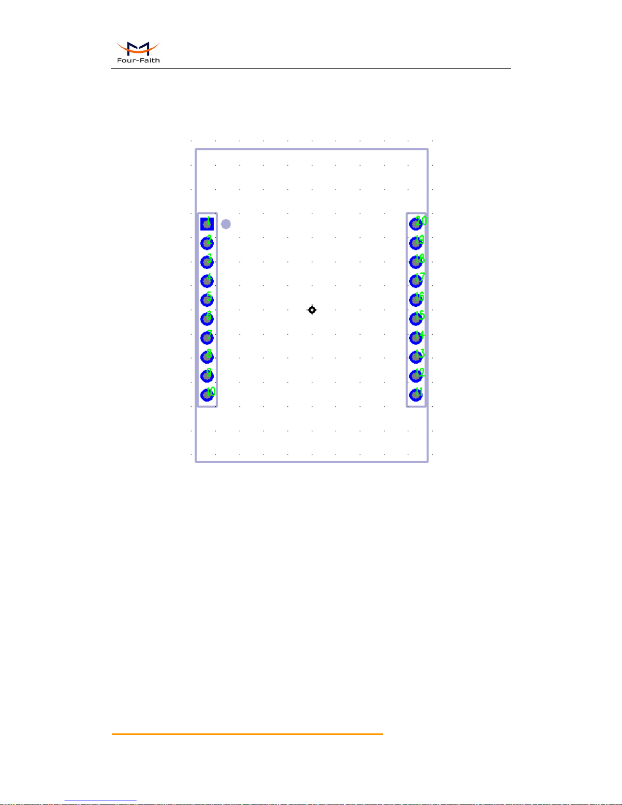
2.1 Module Signal Definition
Figure 2-1 Module Pin Distributing

F8913D User Manual
Xiamen Four-Faith Communication Technology Co.,Ltd. Page 14 of 99
Add: J1-J3,3rdFloor,No.44,GuanRiRoad,SoftWare Park,XiaMen .China
http://www.fourfaith.com Tel: +86 592-6300326 6300325 6300324 Fax:+86 592-5912735
Table 2-1 Module signal definition 1-- DIP
Pin Number
Signal Name
Input/Output
Description
1
VCC
N/A
Power Supply
2
DOUT
Output
UART Data Out
3
DIN
Input
UART Data In
4
RD/DE
Output
RD/DE
5
RST
Input
Module Reset
6
D4
Either
GPIO
7
D3
Either
GPIO
8
[reserved]
N/A
N/A
9
SLEEP_RQ
Both
Pin Sleep Control Line
10
GND
N/A
Ground
11
D2
Input
ADC/GPIO
12
CTS
Output
Clear-to-Send
13
SLEEP/ON
Output
SLEEP/ON
14
AVDD5
N/A
VREF
15
Associate
Either
Associate Indicator
16
RTS
Input
Request-to-Send
17
DD
Either
Debug Data
18
DC
Input
Debug Clock
19
D1
Input
ADC/GPIO
20
D0
Input
ADC/GPIO
2.2 UART
The serial communication prot 1 is UART.The signal define as Table 2-2:
Table 2-2 UART Signal Assignments
UART Signal Name
Pin Number
TX 2 RX 3 CT
12
RT
16
Please reference the chapter 3 for the UART operation details.

F8913D User Manual
Xiamen Four-Faith Communication Technology Co.,Ltd. Page 15 of 99
Add: J1-J3,3rdFloor,No.44,GuanRiRoad,SoftWare Park,XiaMen .China
http://www.fourfaith.com Tel: +86 592-6300326 6300325 6300324 Fax:+86 592-5912735
2.3 GPIO Specification
The F8913D have 5 GPIO.The DC characteristics as the Table 2-4.
Table 2-4 GPIO DC Characteristics (Ta=25°C,VCC=3V)
Parameters
Test Conditions
Min Type Max
Logic 0 input voltage (V)
0.5
Logic 1 input voltage (V)
2.5
Logic 0 input current (nA)
Input equals 0V
-50 50
Logic 1 input current (nA)
Input equals VCC
-50 50
I/O-pin pullup and pulldown resistors
20
Logic 0 input voltage,4-mA pins (V)
Output load 4mA
0.5
Logic 1 input voltage,4-mA pins (V)
Output load 4mA
2.4
Logic 0 input voltage,20-mA pins (V)
Output load 20mA
0.5
Logic 1 input voltage,20-mA pins (V)
Output load 20mA
2.4
Please reference the chapter 3 for the GPIO configuration and operation details.
F8913D User Manual
Xiamen Four-Faith Communication Technology Co.,Ltd. Page 16 of 99
Add: J1-J3,3rdFloor,No.44,GuanRiRoad,SoftWare Park,XiaMen .China
http://www.fourfaith.com Tel: +86 592-6300326 6300325 6300324 Fax:+86 592-5912735
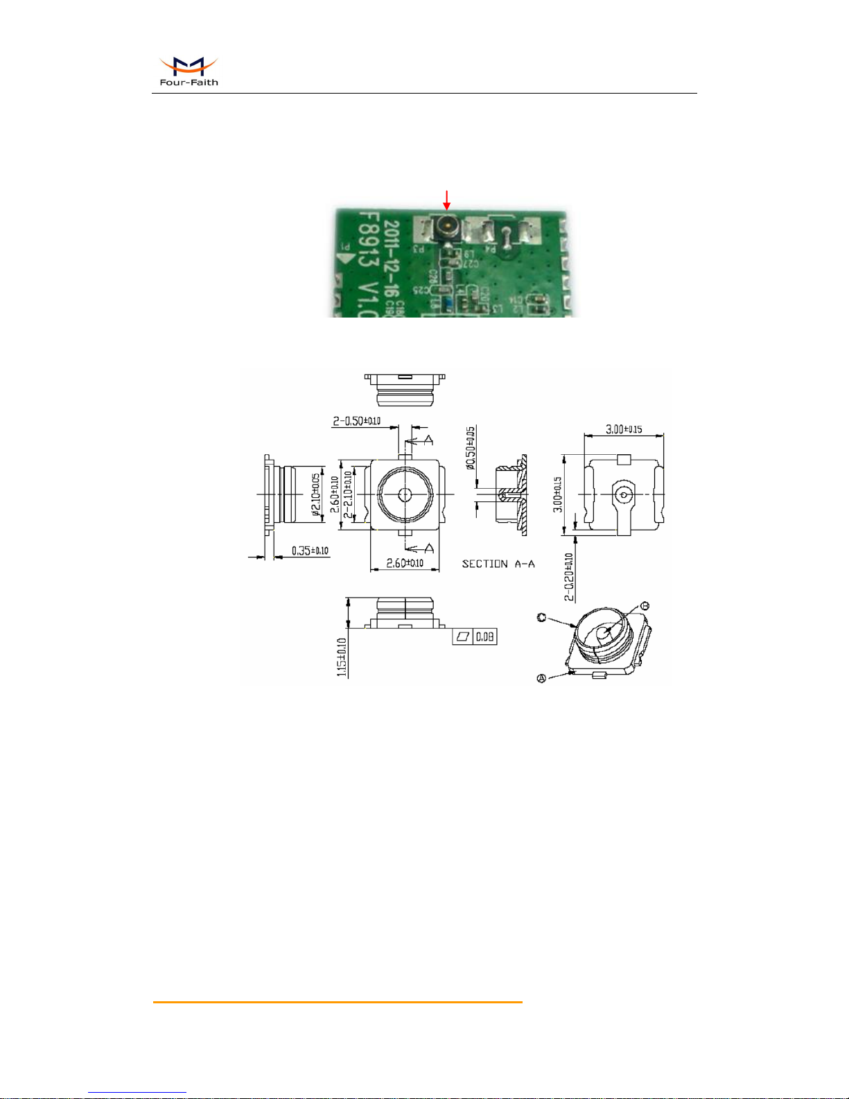
2.4 Antenna Interface
The Antenna connector part number:MM9329-2700/Murata,as the Figure 2-2:
Figure 2-2 Antenna Connector
MM9329-2700/Murata dimension as the Figure 2-3:
Figure 2-3 The MM9329-2700/Murata dimension
Antenna Conntector
F8913D User Manual
Xiamen Four-Faith Communication Technology Co.,Ltd. Page 17 of 99
Add: J1-J3,3rdFloor,No.44,GuanRiRoad,SoftWare Park,XiaMen .China
http://www.fourfaith.com Tel: +86 592-6300326 6300325 6300324 Fax:+86 592-5912735
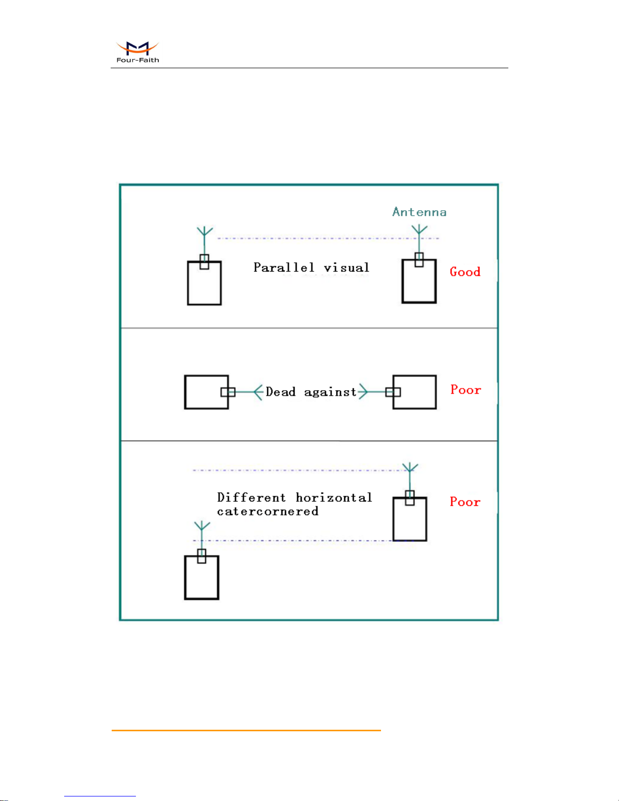
2.5 Antenna Installation
1、 Install the antenna far away from the large area metal and ground.
2、 Keep the antennas visual.
3、 Minimize obstructions between the antennas.
4、 Reduce the extension cords of the antenna.
The performance of different antenna installation types, as the figure 2-4.
Figure 2-4 Different antenna installation types

F8913D User Manual
Xiamen Four-Faith Communication Technology Co.,Ltd. Page 18 of 99
Add: J1-J3,3rdFloor,No.44,GuanRiRoad,SoftWare Park,XiaMen .China
http://www.fourfaith.com Tel: +86 592-6300326 6300325 6300324 Fax:+86 592-5912735
2.6 Firmware Performance Specifications
Table 2-6 Firmware Performance Specfication
UART
Baudrate
115200 (Default)
Configuration
8/N/1 (Default)
Max serial buffer size
300Bytes
XOR
1-byte XOR
Command Mode
AT Command
HEX Command
Network
Max nodes quantity
65000
Node number range
0~65000
0:The center node
65535:Broadcast
Wakeup Mode
Extenal Wakeup Mode
Timer Wakeup Mode
2.7 Absolute Maximum Ratings
Table 2-7 Absolute Maximum Ratings
Parameters
Min
Max
Unit
Supply Voltage
-0.3
3.9
V
Voltage on any digital pin
VCC-0.3
VCC+0.3 (≤3.9)
V
Input RF level
10
dBm
Storage temperate range
–40
125
°C
Notice: Stresses beyond those listed under Absolute Maximum Ratings may cause permanent
damage to the device.
F8913D User Manual
Xiamen Four-Faith Communication Technology Co.,Ltd. Page 19 of 99
Add: J1-J3,3rdFloor,No.44,GuanRiRoad,SoftWare Park,XiaMen .China
http://www.fourfaith.com Tel: +86 592-6300326 6300325 6300324 Fax:+86 592-5912735
Chapter 3 Communication Interface Operation
3.1 UART
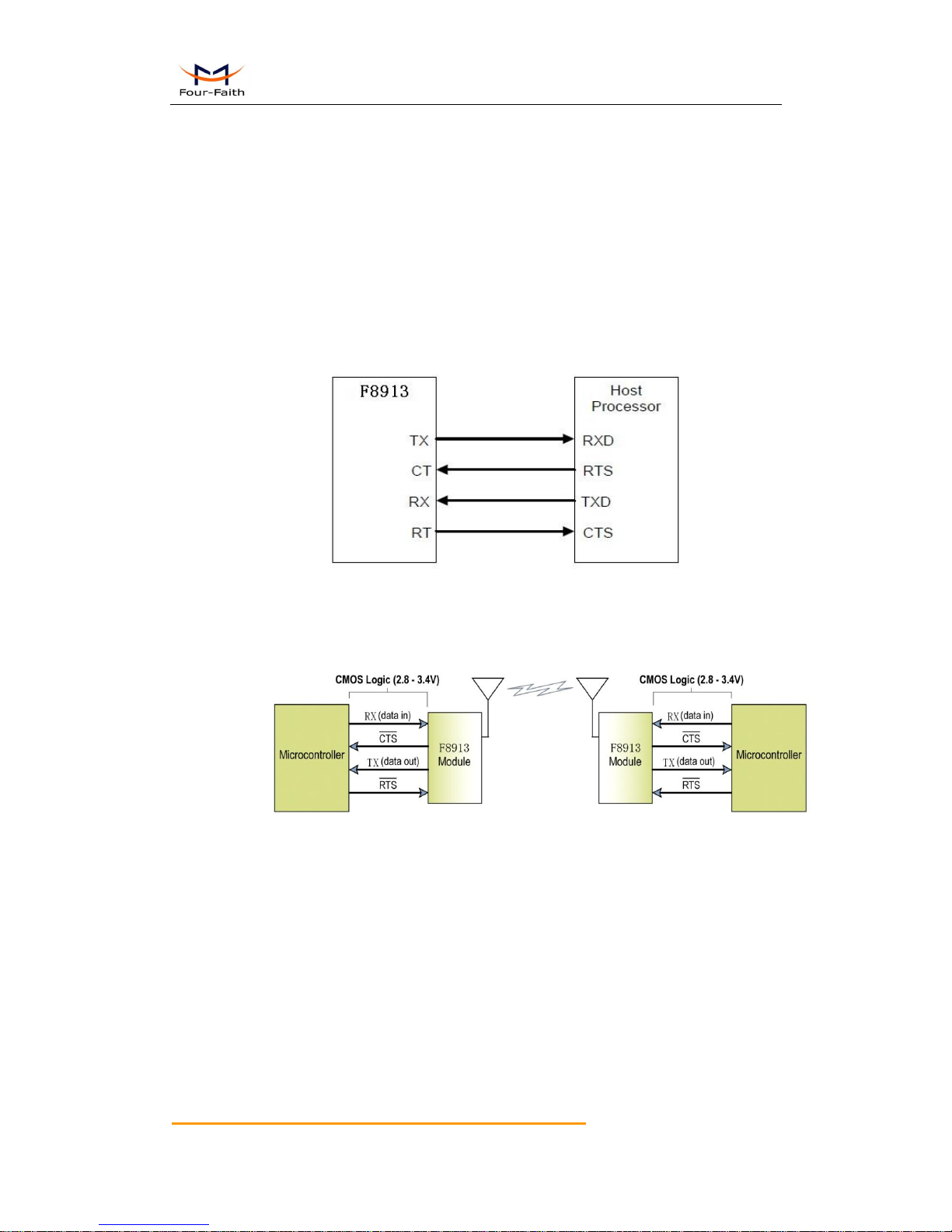
3.1.1 UART signal description
TX: Data transmit
RX: Data receive
CT: Clear to Send
RT: Request to send
3.1.2 UART connections
Figure 3-1 UART connection diagram
Note: device default has no hardware flow control
Example: As the figure 3-2, The UART convert to RF system can be set up when
the device with a UART interface connect to F8913D directly.
Figure 3-2 The UART convert to RF system

F8913D User Manual
Xiamen Four-Faith Communication Technology Co.,Ltd. Page 20 of 99
Add: J1-J3,3rdFloor,No.44,GuanRiRoad,SoftWare Park,XiaMen .China
http://www.fourfaith.com Tel: +86 592-6300326 6300325 6300324 Fax:+86 592-5912735
3.1.3 UART Characteristics
UART data format
Start
D0
D1
D2
D3
D4
D5
D6
D7
Stop
Figure 3-3 Data format
1) Communication interface: UART
2) Baudrate: 300,600,1200,2400,4800,9600 ,19200,38400,57600 ,115200 bps (default)
3) Start bit: 1bit
4) Data bit: 8bit
5) Stop bit: 1bit,2bit
6) Checksum: none,odd,even
UART support full-duplex. The communication can launch by an external device or
the module itself.
The 8-N-1 mode, each data byte includes a start bit (low), 8 data, and a stop bit
(high). The following figure 3-3 illustrates the serial data bit patterns.The data packet is
0x1F.
Figure 3-4 0x1F bit patterns

F8913D User Manual
Xiamen Four-Faith Communication Technology Co.,Ltd. Page 21 of 99
Add: J1-J3,3rdFloor,No.44,GuanRiRoad,SoftWare Park,XiaMen .China
http://www.fourfaith.com Tel: +86 592-6300326 6300325 6300324 Fax:+86 592-5912735
3.2 Analog and Digital I/O
3.2.1 Signal Definition
The F8913D support ADC and digital I/O line passing.The ADC and digital I/O can be
inquired and configured by AT commands.The pins support ADC and digital I/O fuctions
are listing in the table 3-1
Table 3-1 Analog and Digital I/O pins (SMT)
Pin Number
Pin Name
Default Function
6
D4
GPIO 7 D3
GPIO
11
D2
ADC/GPIO
19
D1
ADC/GPIO
20
D0
ADC/GPIO
3.2.2 Function Description
1.Digital I/O
The Digital D3&D4 support 4mA drive capability.
2.ADC
The ADC support 12 bits of resolution. The ADC input voltage range is 0V to 5V.
Please configure the right value when operate the I/O.
Table 3-3 I/O Configuration
Value
Description
0
Disabled
1
ADC
2
GPIO input
3
GPIO output low
4
GPIO output high
5
Pluse input count
Notice: Please reference the AT command “AT+DMn” in the charpter 4 for the details.

F8913D User Manual
Xiamen Four-Faith Communication Technology Co.,Ltd. Page 22 of 99
Add: J1-J3,3rdFloor,No.44,GuanRiRoad,SoftWare Park,XiaMen .China
http://www.fourfaith.com Tel: +86 592-6300326 6300325 6300324 Fax:+86 592-5912735
Chapter 4 Parameter Configuration
4.1 Zigbee Description
4.1.1 Device Type Description
ZigBee device has three types:coordinator,router and end device.They all can transmit and
receive data.
4.1.1.1 Coordinator
This is the device that “starts” a ZigBee network. It is the first device on the network. The
coordinator node scans the RF environment for existing networks, chooses a channel and a
network identifier (also called PAN ID) and then starts the network.
Note that the role of the Coordinator is mainly related to starting up and configuring the
network. Once that is accomplished, the Coordinator behaves like a Router node (or may even go
away). The continued operation of the network does not depend on the presence of the
Coordinator due to the distributed nature of the ZigBee network.
4.1.1.2 Router
A Router performs functions for allowing other devices to join the network multi-hop routing
assisting in communication for its child battery-powered end devices.
In general, Routers are expected to be active all the time and thus have to be mains-powered.
4.1.1.3 End Device
An end-device has no specific responsibility for maintaining the network infrastructure, so it
can sleep and wake up as it chooses. Thus it can be a battery-powered node.

F8913D User Manual
Xiamen Four-Faith Communication Technology Co.,Ltd. Page 23 of 99
Add: J1-J3,3rdFloor,No.44,GuanRiRoad,SoftWare Park,XiaMen .China
http://www.fourfaith.com Tel: +86 592-6300326 6300325 6300324 Fax:+86 592-5912735
4.1.2 ZigBee Network Description
4.1.2.1 Form a ZigBee Network Procedure
(1)The coordinator node scans the RF environment for existing networks, chooses a
channel and a network identifier (also called PAN ID) and then starts the network.
(2)Router or end device also scans the RF environment for existing networks, chooses a
channel and a network identifier (also called PAN ID) and then join the network.
(3)The coordinator’s node address fixed to 0x0000,router’s or end device’s node address
can be assigned randomly or configured previously.
(4)The nodes in the network can use node address transmit or receive data.。
NOTE:In a ZigBee network,just only using one coordinator.
4.1.2.2 Physical Channel
ZigBee is based on IEEE 802.15.4 that has defined the MAC layer and physical layer. IEEE
802.15.4 also defined 3 work band 2.5GHz(global),868MHz(Europe) and 915MHz(USA),they
respectively has highest 250kbit/s, 40kbit/s, 20kbit/s transmission rate. On the three band has 27
work channels in total. 2.4GHz has 16 channels, 915MHz has 10 channels, 868MHz has only one
channel.
Four-Faith ZigBee product works on 2.4GHz band, and has 16 physical channel. In AT
command mode ,we send “AT+CHA=N”,(N=11~26) to configure the channel. We recommend
15 ,20 ,25 ,26 channel .
4.1.2.3 PAN ID
ZigBee network also calls personal area network, every personal area network has unique
Pan ID.This Pan ID is used on every device in a same ZigBee network.
Four-Faith ZigBee product can preconfigure a Pan ID and randomly select a Pan ID. In AT
command mode ,we send “AT+PID=N”,(N=0-65531),if PID=65535 ,it will randomly select a Pan
ID.
4.1.2.4 Node address
ZigBee device has two address types: 64 bit MAC address and 16 bit node address. 64 bit
MAC address is unique in the world, and used in the product life. 16 bit node address usually
assigned when the device joined in the network. It’s unique in a same Pan ID network. We use
node address to send and receive data.
Four-Faith ZigBee product can preconfigure a node address and randomly assigned a node
address. In AT command mode ,we send “AT+NID=N”,(N=0-65527), if NID=65535, it will
randomly assigned a node address.
F8913D User Manual
Xiamen Four-Faith Communication Technology Co.,Ltd. Page 24 of 99
Add: J1-J3,3rdFloor,No.44,GuanRiRoad,SoftWare Park,XiaMen .China
http://www.fourfaith.com Tel: +86 592-6300326 6300325 6300324 Fax:+86 592-5912735
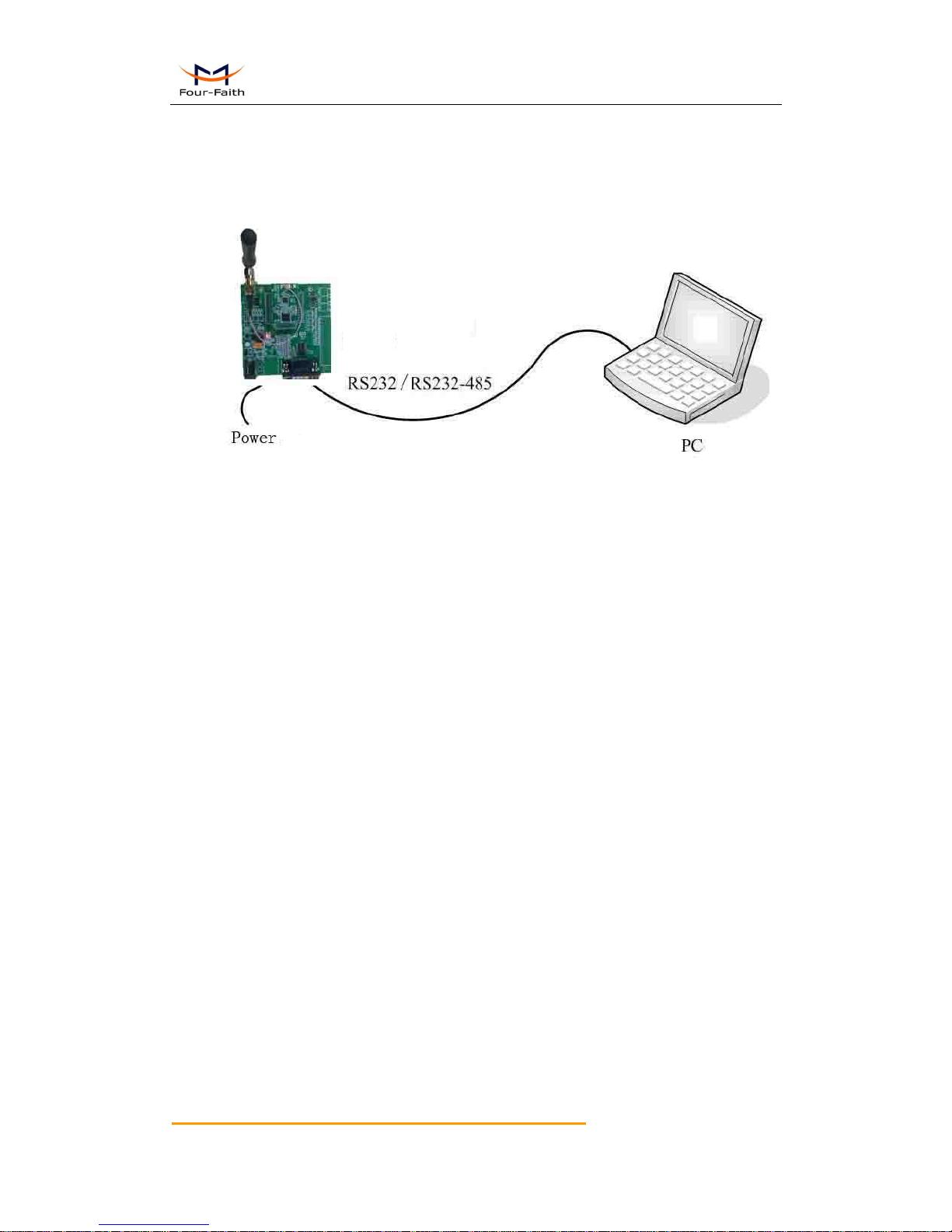
4.2 Configuration Connection
Before configuration, it’s need to connect the F8913D with a host controller.The host
controller could be a PC or other device which contain UART port. You can connect the F8913D
with PC by the Four-Faith F8913D EVB, as showing in the figure 4-1.
Figure 4-1 F8913D EVB connect with PC
4.3 Configuration Introduction
There are two ways to configure the device:
Configuration software tool: All the settings are configured through the shipped
software tool. It’s necessary to have one PC to run this tool.
Extended AT command: All the settings are configured through AT command, so any
device with serial port can configure it. Before configuration with AT command, you
should make device enter configure state.
The following describes how to configure device with AT command .At the same time, it
gives out the corresponding the configure software tool of each configuration item.
Note: When device powers up, it has three second configuration time.During this time, the netwok
not works,and the serial’s baudrate is 115200,no parity, 1 stop bit. Send the 3-character command
sequence“+++”twice through serial port.Then it goes into AT command configuration.
F8913D User Manual
Xiamen Four-Faith Communication Technology Co.,Ltd. Page 25 of 99
Add: J1-J3,3rdFloor,No.44,GuanRiRoad,SoftWare Park,XiaMen .China
http://www.fourfaith.com Tel: +86 592-6300326 6300325 6300324 Fax:+86 592-5912735
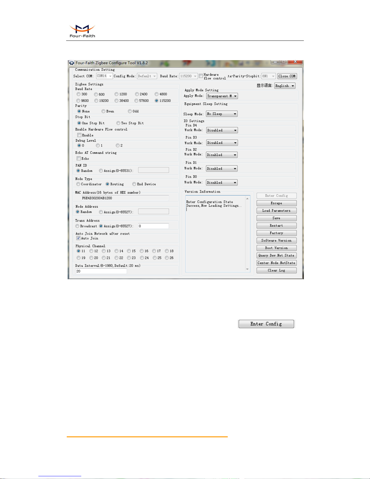
4.3.1 Run the configure Tool: ZigbeeConfigure.exe
The “Communication Setting” column shows the current serial port settings. To configure
ZigBee modules, please choose the correct serial port parameters ,then open the serial port. If the
button text is“Close”, it shows the serial port now has been opened. If the text is “Open”, you
should open the port first.
When you had configure the correct serial port,please press the
bottom, and follow the prompt,he node will enter configuration state.

F8913D User Manual
Xiamen Four-Faith Communication Technology Co.,Ltd. Page 26 of 99
Add: J1-J3,3rdFloor,No.44,GuanRiRoad,SoftWare Park,XiaMen .China
http://www.fourfaith.com Tel: +86 592-6300326 6300325 6300324 Fax:+86 592-5912735
4.4 Modes of Operation
F8913D supports three modes of Operation:Transparent Mode,AT Command Mode and API
Mode.
4.4.1 Transparent mode
When operationg in transparent mode the modules act as a serial line replacement. All
UART data received through the DIN pin is queued up for RF transmission. When data is received,
the data is sent out through the DOUT pin.
Re-power module enter the transparent mode by default.
To enter transparent mode:
In the AT command mode,send “AT+ESC<CR><LF>”through serial port.
In the API mode, send “FE 01 21 2A 00 0A” through serial port.

F8913D User Manual
Xiamen Four-Faith Communication Technology Co.,Ltd. Page 27 of 99
Add: J1-J3,3rdFloor,No.44,GuanRiRoad,SoftWare Park,XiaMen .China
http://www.fourfaith.com Tel: +86 592-6300326 6300325 6300324 Fax:+86 592-5912735
4.4.2 AT command mode
AT command mode is a multiple function operation. This mode can configure the modules
parameters,send data and recive data.
To enter AT command mode:
In the transparent mode,send the 3-character command sequence“+++”twice through
serial port.
In the API mde,send “FE 01 21 2A 00 0A” through serial port.
CHECK the AT command mode,send “AT<CR><LF>” through serial port, it will return
“OK”.
All AT command line should begin with “AT” or “at” and end with “<CR><LF>”.In
general, the AT command includes three forms, as shown in table 3-1.
Table 3-1 AT command forms
Form
Description
Instance
Set
Set the custom parameters
AT+XXX=<……>
Query
Query the current parameters
value
AT+XXX?
Execute
Execute the command
AT+XXX
Note: every configure item is set, it should send save command.Network param(PAN ID,Physical
Channel ,node address or device type changed),sleep param and serial param change should
re-power device.
4.4.2.1 Set device PAN ID: AT+PID
Form
Command
Return
Set
AT+PID=<number strings>
0K
ERROR
Query
AT+PID?
+PID: number strings
OK
Parameter description :
number strings range: 0~65531,Set unique PAN ID
65535, System will assign a stochastic PAN ID
Default:65535

F8913D User Manual
Xiamen Four-Faith Communication Technology Co.,Ltd. Page 28 of 99
Add: J1-J3,3rdFloor,No.44,GuanRiRoad,SoftWare Park,XiaMen .China
http://www.fourfaith.com Tel: +86 592-6300326 6300325 6300324 Fax:+86 592-5912735
4.4.2.2 Query device current PAN ID: AT+PCD
Form
Command
Return
Query
AT+PCD?
+PCD: number strings
OK
Attention: This command is different from “AT+PID”. When the PAN ID is assigned by system
and the node joined in the network , we can use this command to query the current PAN ID.
4.4.2.3 Set device physical channel: AT+CHA
Form
Commad
Return
Set
AT+CHA=<number strings>
0K
ERROR
Query
AT+CHA?
+CHA: number string
OK
Parameter description :
number string range: 11~26
Default: 11
4.4.2.4 Query device MAC address: AT+MID
Form
Command
Return
Query
AT+MID?
+MID: hexadecimal strings
OK
Attention: This command is read only. It will return 16 hexadecimal strings.
For example: 0x051B9B01004B1200

F8913D User Manual
Xiamen Four-Faith Communication Technology Co.,Ltd. Page 29 of 99
Add: J1-J3,3rdFloor,No.44,GuanRiRoad,SoftWare Park,XiaMen .China
http://www.fourfaith.com Tel: +86 592-6300326 6300325 6300324 Fax:+86 592-5912735
4.4.2.5 Set device type: AT+TYP
Form
Command
Return
Set
AT+TYP=<number string>
0K
ERROR
Query
AT+TYP?
+TYP: number string
OK
Parameter description :
number string range: 0 = Coordiantor
1 = Routerr
2 = End Device
Default:1
4.4.2.6 Set device node address: AT+NID
Form
Command
Return
Set
AT+NID=<number strings>
0K
ERROR
Query
AT+NID?
+NID: number strings
OK
Parameter description :
number string range: 0~65527,Set unique node address
65535, System will assign a stochastic node address
Default:65535
Attention : When coordiantor form a network, its node address is fixed to 0, the router and end
device’s node address must be non-zero.
4.5.2.7 Query device current node address : AT+NCD
Form
Command
Return
Query
AT+NCD?
+NCD: number strings
OK
Attention: This command is different from “AT+NID”. When the node address is assigned by
system and the node joined in the network , we can use this command to query the current node
address.
F8913D User Manual
Xiamen Four-Faith Communication Technology Co.,Ltd. Page 30 of 99
Add: J1-J3,3rdFloor,No.44,GuanRiRoad,SoftWare Park,XiaMen .China
http://www.fourfaith.com Tel: +86 592-6300326 6300325 6300324 Fax:+86 592-5912735
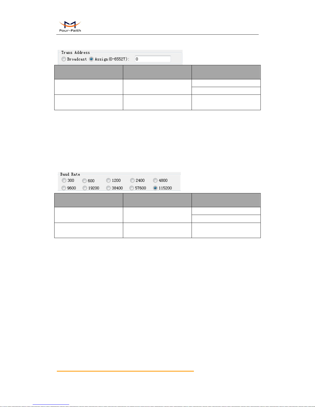
4.4.2.8 Set decice transparent address: AT+TID
Form
Command
Return
Set
AT+TID=<number strings>
0K
ERROR
Query
AT+TID?
+TID: number strings
OK
Parameter description :
number strings range: 0~65527,Set unique node trans address
65535, broadcast address
Default:0
4.4.2.9 Set device serial
4.4.2.9.1 Set device serial baudrate: AT+IPR
Form
Command
Return
Set
AT+IPR=<number string>
0K
ERROR
Query
AT+IPR?
+IPR: number string
OK
Parameter description :
number strings range: 0 = 300 1 = 600 2 = 1200
3 = 2400 4 = 4800 5 = 9600
6 = 19200 7 = 38400 8 = 57600
9 = 115200
Default:9
 Loading...