

Four-Faith F8X14 Series, F8114, F8214, F8414, F8614 User Manual
...
F8X14 Series
User Manual
Document Version
Page
V2.0.0
Product Name:
Total: 49
F8X14 Series User Manual
Model
Product Type
F8114
ZigBee + GPRS IP MODEM
F8214
ZigBee + CDMA IP MODEM
F8414
ZigBee + WCDMA IP MODEM
F8614
ZigBee + EVDO IP MODEM
The user manual is suitable for the following model:
Xiamen Four-Faith Smart Power Technology Co., Ltd.
Add:Floor 11, Area A06, No 370, chengyi street, Jimei, Xiamen
Tel:+86 592-5907276 Fax:+86 17750019379
Web: en.four-faith.com
Files Revised Record
Date
Version
Remark
Author
2011.04.19
V0.5
Draft
Tracy.zheng
2011.06.28
V0.6
Modification
Tracy.zheng
2011.07.14
V0.7
Modification
Tracy.zheng
2012.07.24
V0.8
Modification
David
2013.03.20
V1.0
Modification
David
2016.02.01
V1.1
Modify some parameters of Zigbee
zxz
2017.10.10
V2.0.0
Change of company address
LXP
F8X14 Series User Manual

F8X14 Series User Manual
Copyright Notice
All contents in the files are protected by copyright law, and all copyrights are reserved by Xiamen
Four-Faith Communication Technology Co., Ltd. Without written permission, all commercial
use of the files from Four-Faith are forbidden, such as copy, distribute, reproduce the files, etc.,
but non-commercial purpose, downloaded or printed by individual (all files shall be not revised,
and the copyright and other proprietorship notice shall be reserved) are welcome.
Trademark Notice
Four-Faith、四信、 、 、 are all registered trademarks of Xiamen
Four-Faith Communication Technology Co., Ltd., illegal use of the name of Four-Faith,
trademarks and other marks of Four-Faith is forbidden, unless written permission is authorized in
advance.

F8X14 Series User Manual

F8X14 Series User Manual
Contents
Contents
Chapter 1 Brief Introduction of Product............................................................................................. 6
1.1 General.................................................................................................................................. 6
1.2 Features and Benefits............................................................................................................ 6
1.3 Working Principle..................................................................................................................7
1.4 Specifications........................................................................................................................ 8
Chapter 2 Installation Introduction................................................................................................... 12
2.1 General................................................................................................................................ 12
2.2 Encasement List.................................................................................................................. 12
2.3 Installation and Cable Connection......................................................................................12
2.4 Power...................................................................................................................................15
2.5 Indicator Lights Introduction.............................................................................................. 15
Chapter 3 Configuration....................................................................................................................16
3.1 Configuration Connection...................................................................................................16
3.2 Configuration Introduction................................................................................................. 16
3.3 Run the configure Tool: IP Modem Configure.exe............................................................ 17
3.4 Re-power IP MODEM........................................................................................................ 18
3.5 Configuration(F8114 for example)..................................................................................... 18
3.5.1 Data Service Center Settings................................................................................... 18
3.5.2 IP MODEM Settings................................................................................................ 21
3.5.3 Other Settings...........................................................................................................26
3.5.4 Scheduled Power On/Off Setting.............................................................................30
3.5.5 ZigBee Setting..........................................................................................................30
3.5.6 ModBus Setting........................................................................................................33
3.5.7 Port Setting...............................................................................................................33
3.5.8 SMS Setting............................................................................................................. 34
3.6 SMS Config Setting............................................................................................................ 35
3.7 Functions............................................................................................................................. 36
3.8 Work State Switch............................................................................................................... 37
Chapter 4 Data Transfer Testing........................................................................................................38
4.1 Testing Environment........................................................................................................... 38
4.2 Testing steps........................................................................................................................ 39
Appendix........................................................................................................................................... 45
Appendix A Accord Format....................................................................................................... 48
1.1 General
High-powered industrial cellular module
High-powered industrial ZigBee module
High-powered industrial 32 bits CPU
Support low power consumption mode, including multi-sleep and trigger modes to reduce the
Embedded Real Time Clock(RTC) circuit which can realize timing online/offline function
Housing: iron, providing IP30 protection
Power range: DC 5~35V
Support hardware and software WDT
Support auto recovery mechanism, including online detect, auto redial when offline to make
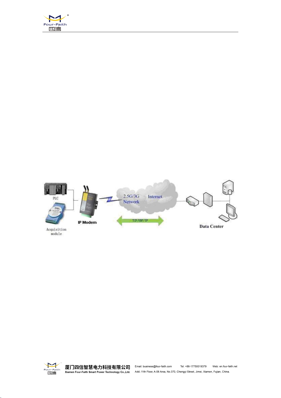
F8X14 IP MODEM is a kind of data terminal device that provides data transfer function by
public cellular network and ZigBee network.
It adopts high-powered industrial 32 bits CPU and embedded real time operating system. It
supports RS232, RS485 (or RS422) and ZigBee port that can conveniently and transparently
connect one device to a cellular network, allowing you to connect to your existing serial and
ZigBee devices with only basic configuration. It has low power consumption states in which the
power consumption could be 1ower than 1mA@12VDC. It has compatible digital I/O channel,
ADC, input pulse counter and pulse wave output function.
It has been widely used on M2M fields, such as intelligent transportation, smart grid,
industrial automation, telemetry, finance, POS, water supply, environment protection, post,
weather, and so on.
F8X14 Series User Manual
Chapter 1 Brief Introduction of Product
1.2 Features and Benefits
Design for Industrial Application
power dissipation farthest
Stability and Reliability
it always online
RS232/RS485/RS422 port: 15KV ESD protection
SIM/UIM port: 15KV ESD protection
Power port: reverse-voltage and overvoltage protection
Antenna port: lightning protection(optional)
Adopt terminal block interface, convenient for industrial application
Support standard RS232 and RS485(or RS422) port that can connect to serial devices directly
TTL logic level RS232 interface can be customized
Support intellectual mode, enter into communication state automatically when powered
Provide management software for remote management
Support several work modes
Convenient configuration and maintenance interface
Support data transfer by cellular and ZigBee network
Support TCP server and support multi TCP client connection(optional)
Support double data centers, one main and another backup
Supply 5 I/O channels, compatible 2 pulse wave output channels, 2 analog inputs and one
Support multi data centers and it can support 5 data centers at the same time
Support multi online trigger ways, including SMS, ring and data. Support link disconnection
Support dynamic domain name(DDNS) and IP access to data center
Design with standard TCP/IP protocol stack
Support APN/VPDN
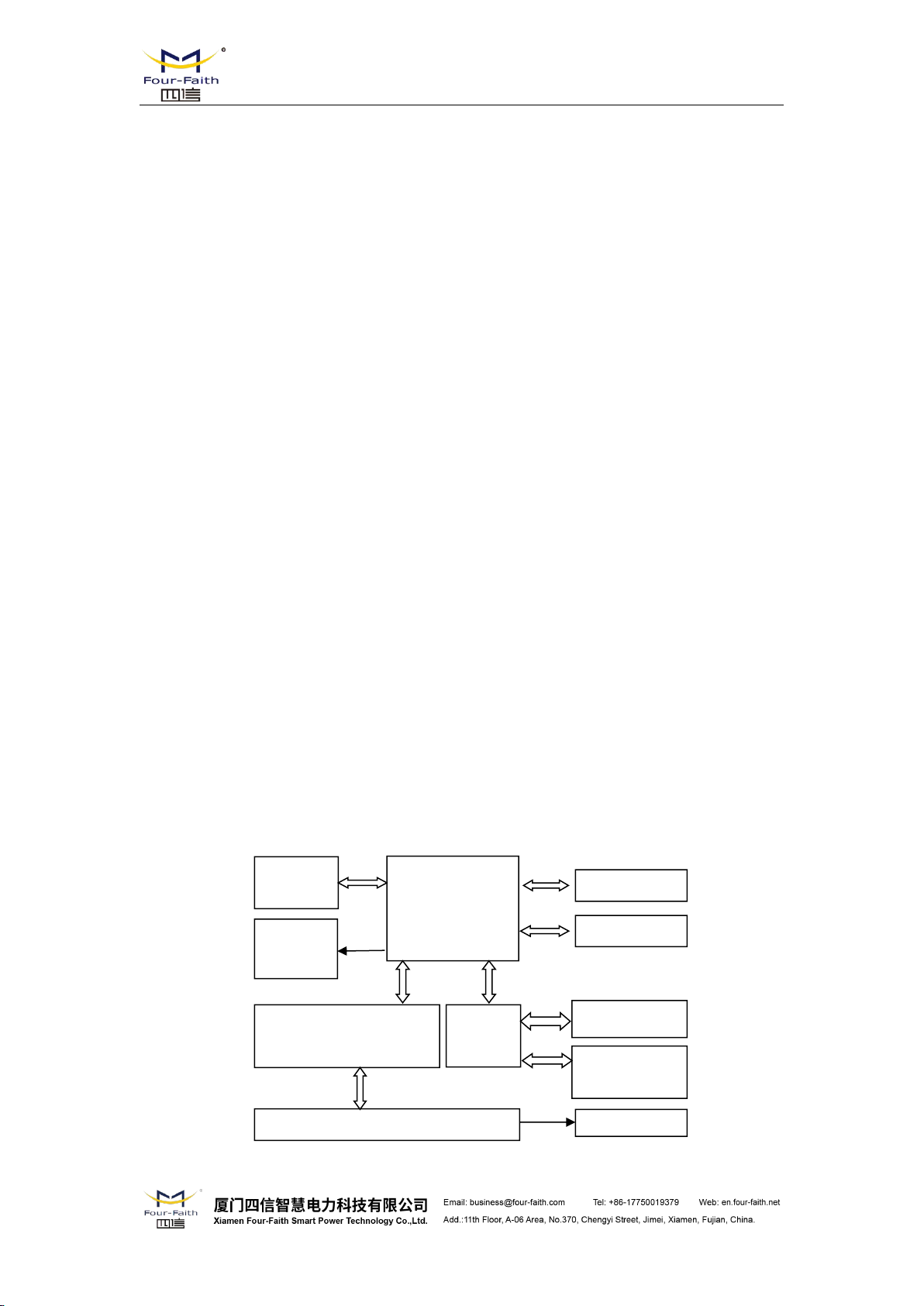
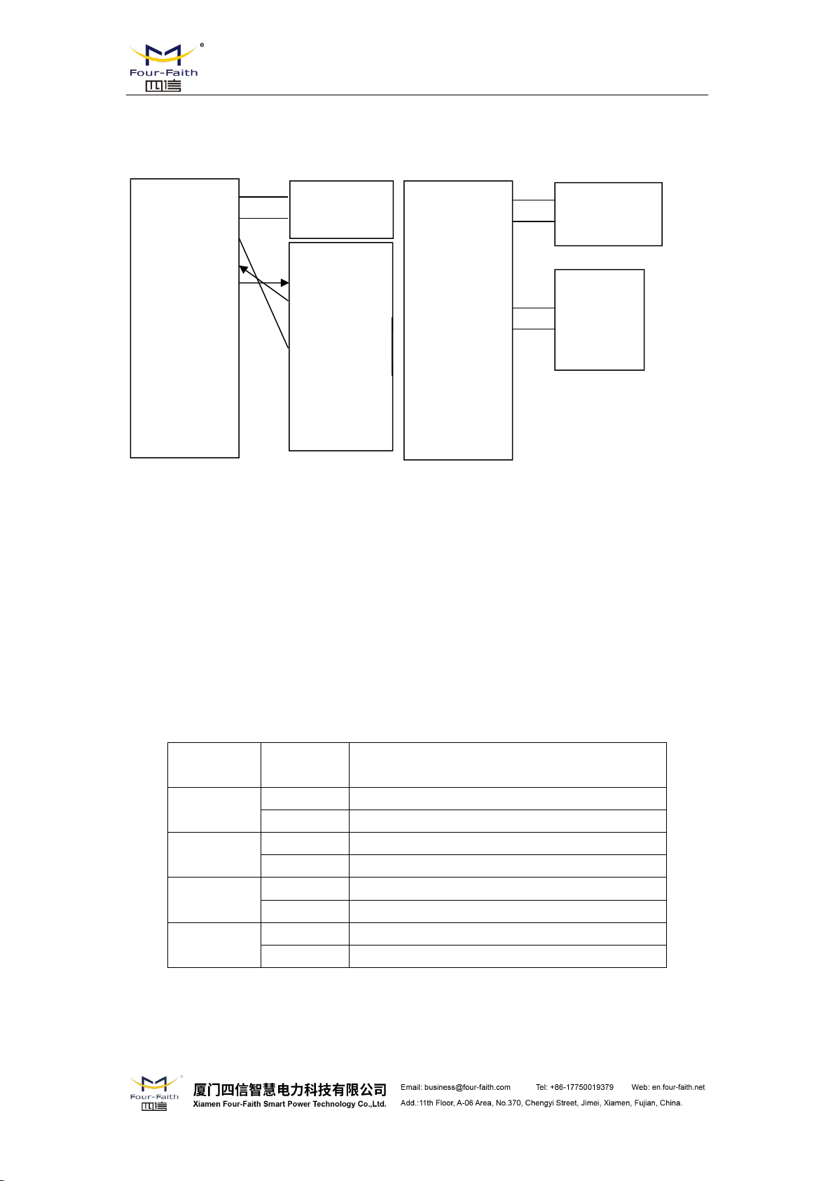
Cellular
Module
MCU
Antenna
SIM/UIM
Interface
Indicator
Lights
SRAM&
FLASH
WDT Module
RTC Module
User Interface
RS232/RS485/RS422
Module
Power Module
Standard and Convenience
High-performance
F8X14 Series User Manual
pulse input counters.
when timeout
1.3 Working Principle
The principle chart of the IP MODEM is as following:
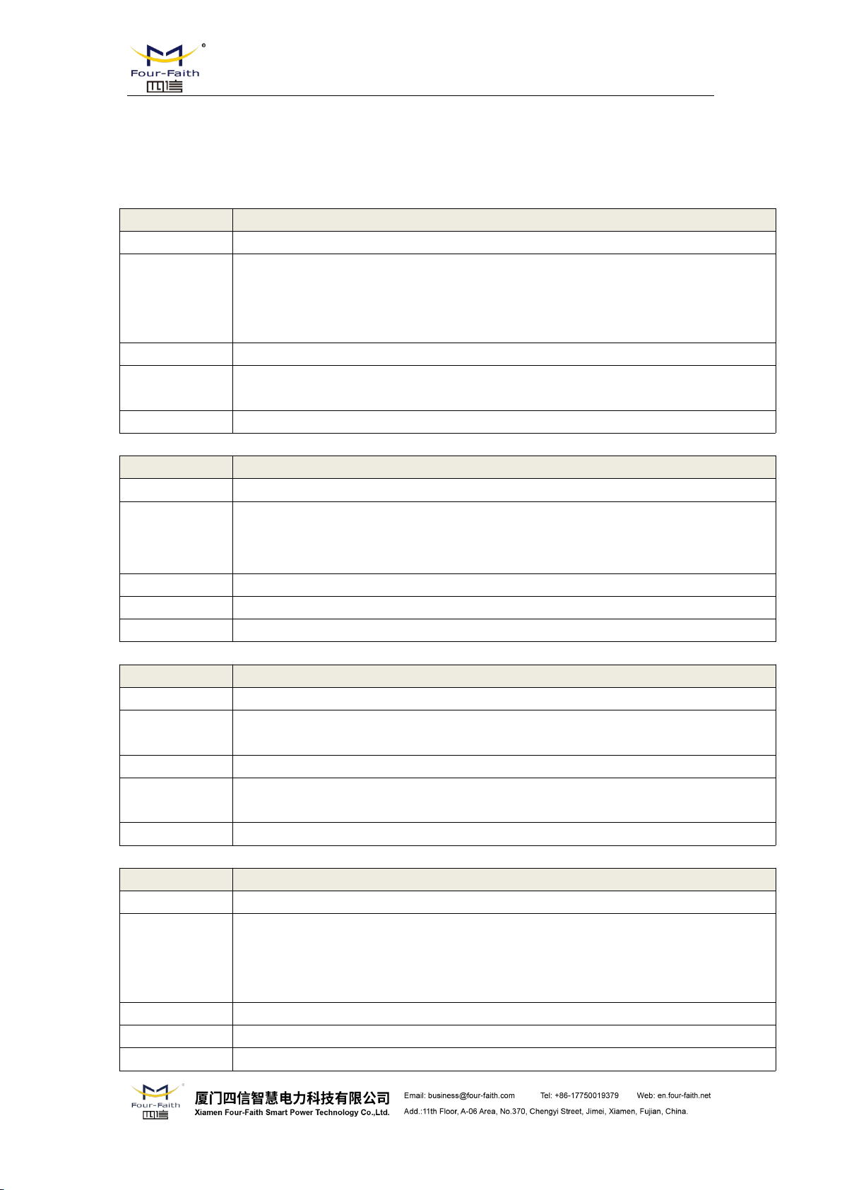
1.4 Specifications
Item
Content
Cellular Module
Industrial cellular module
Standard and Band
EGSM900/GSM1800MHz,
GSM850/900/1800/1900MHz(optional)
Compliant to GSM phase 2/2+
GPRS class 10, class 12(optional)
Bandwidth
85.6Kbps
TX power
GSM850/900: <33dBm
GSM1800/1900: <30dBm
RX sensitivity
<-107dBm
Item
Content
Cellular Module
Industrial cellular module
Standard and Band
CDMA2000 1xRTT 800MHz
CDMA800/1900MHz(optional)
CDMA450MHz(optional)
Bandwidth
153.6Kbps
TX power
<30dBm
RX sensitivity
<-104dBm
Item
Content
Cellular Module
Industrial cellular module
Standard and Band
GSM850/900/1800/1900MHz
GPRS/EDGE Class 12
Bandwidth
236.8Kbps
TX power
GSM850/900:<33dBm
GSM1800/1900:<30dBm
RX sensitivity
<-106dBm
Item
Content
Cellular Module
Industrial cellular module
Standard and Band
UMTS/WCDMA/HSDPA/HSUPA 850/1900/2100MHz
UMTS/WCDMA/HSDPA/HSUPA 850/900/1900/2100MHz(optional)
GSM850/900/1800/1900MHz
GPRS/EDGE CLASS 12
Bandwidth
HSUPA: 5.76Mbps / HSDPA: 7.2Mbps /UMTS: 384Kbps (DL/UL)
TX power
<24dBm
RX sensitivity
<-109dBm
Cellular Specification
F8114 Specification
F8214 Specification
F8X14 Series User Manual
F8314 Specification
F8414 Specification
F8514 Specification
Item
Content
Cellular Module
Industrial cellular module
Standard and Band
TD-SCDMA/HSDPA/HSUPA 1880-1920/2010-2025MHz
GSM850/900/1800/1900MHz
GPRS/EDGE CLASS 12
Bandwidth
2.8Mbps(down), 2.2Mbps(up)
TX power
<24dBm
RX sensitivity
<-108dBm
Item
Content
Cellular Module
Industrial cellular module
Standard and Band
CDMA2000 1X EVDO Rev A 800MHz
CDMA2000 1X EVDO Rev A 800/1900MHz (optional)
CDMA2000 1X EVDO Rev A 450MHz (optional)
IS-95 A/B、CDMA2000 1xRTT
Bandwidth
3.1Mbps(down), 1.8Mbps(up)
TX power
<23dBm
RX sensitivity
<-104dBm
Item
Content
ZigBee Chip
Industrial ZigBee Chip
Standard and Band
IEEE 802.15.4
ISM 2.4 ~2.5GHz
Indoor/Urban Range
30m
90m(With PA)
Outdoor/RF Line-of-Sight
Range
500m
2000m(With PA)
Transmit Power
2.82mw(+4.5dBm)
100mw(+20dBm) (With PA)
Bandwidth
250Kbps
Receiver Sensitivity
-97dBm
-103dBm(With PA)
Network Topologies
Point-to-Point, Point-to-Multipoint, Peer-to-Peer and Mesh
Number of channels
16 Direct Sequence Channels
Channels
11 to 26
Item
Content
CPU
Industrial 32 bits CPU
FLASH
2MB(Extendable)
SRAM
512KB(Extendable)
F8614 Specification
F8X14 Series User Manual
ZigBee Specification
Hardware System
Interface Type
Item
Content
Serial
1 RS232 port and 1 RS485(orRS422) port, 15KV ESD protection
Data bits: 5, 6 ,7, 8
Stop bits: 1, 1.5, 2
Parity: none, even, odd, space, mark
Baud rate: 110~230400 bps
Indicator
"Power", "ACT", "Online",“ZigBee”
Antenna
Cellular: Standard SMA female interface, 50 ohm
GPS: Standard SMA female interface, 50 ohm
lighting protection(optional)
SIM/UIM
Standard 3V/1.8V user card interface, 15KV ESD protection
Power
Terminal block interface, reverse-voltage and overvoltage protection
Item
Content
Standard Power
DC 12V/0.5A
Power Range
DC 5~35V
Working States
Power Consumption
Communication
50-80mA@12VDC;115-150mA@5VDC
Standby
20mA@12VDC;35mA@5VDC
Sleep
8mA@12VDC;18mA@5VDC
Timing Power
Off
0.6mA@12VDC;1mA@5VDC
Item
Content
Housing
Iron, providing IP30 protection
Dimensions
91x58.5x22 mm
Weight
210g
Item
Content
F8X14 Series User Manual
Power Input
Power Consumption
Physical Characteristics
Environmental Limits

F8X14 Series User Manual
Operating
Temperature
-25~+65ºC(-13~+149℉)
Extended
Operating
Temperature
-30~+75ºC(-22~+167℉)
Storage
Temperature
-40~+85ºC(-40~+185℉)
Operating
Humidity
95% ( Non-condensing)
Chapter 2 Installation Introduction
Name
Quantity
Remark
IP MODEM host
1
2.4G ZigBee Antenna
1
Cellular Antenna
1
Power adapter
1
RS232 data cable
1
optional
RS485 data cable
1
optional
Manual CD
1
Certification card
1
Maintenance card
1
2.1 General
The IP MODEM must be installed correctly to make it work properly.
Warning: Forbid to install the IP MODEM when powered!
2.2 Encasement List
F8X14 Series User Manual
Table 2-1 Encasement List
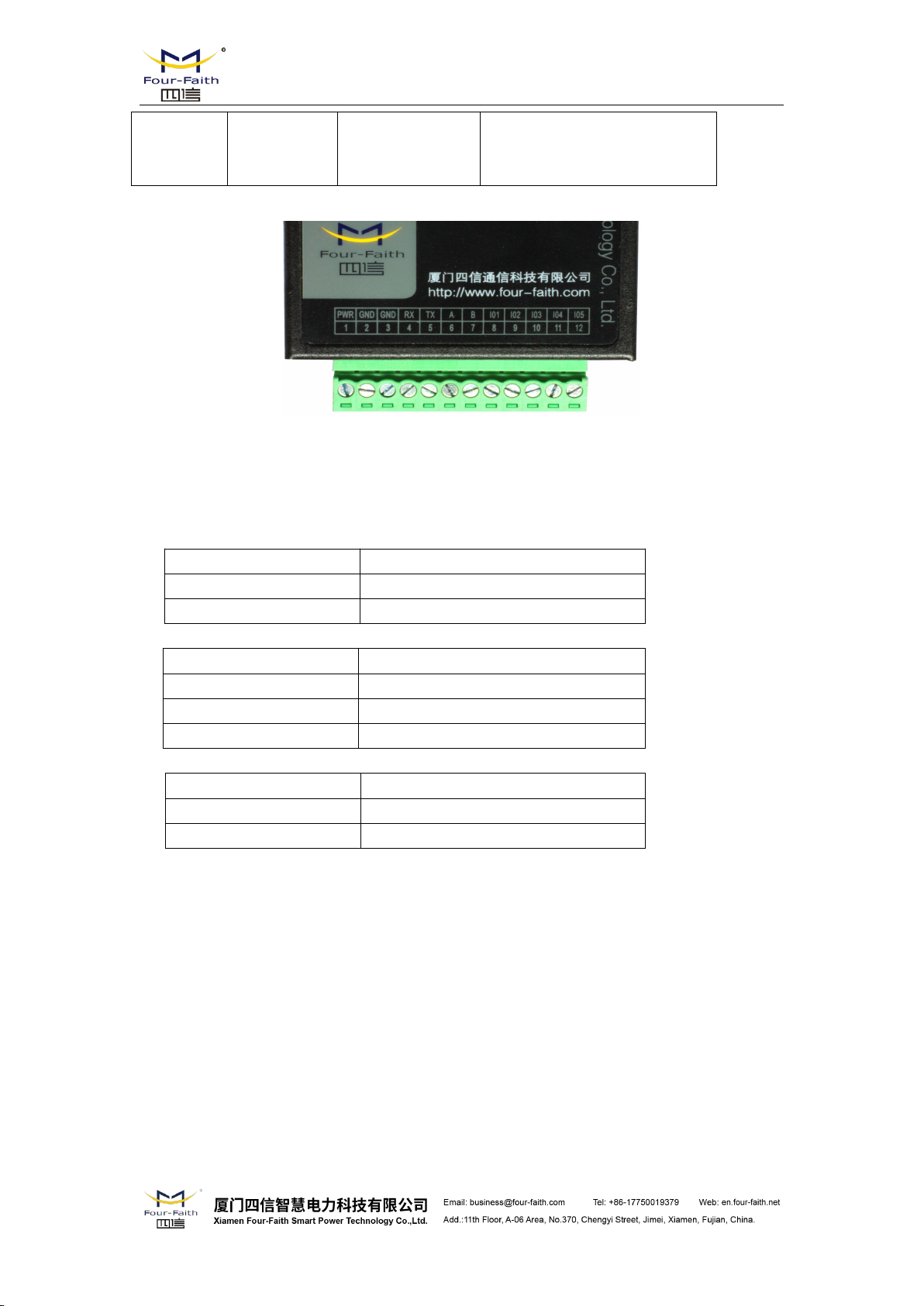
2.3 Installation and Cable Connection
Dimension: (unit: mm)
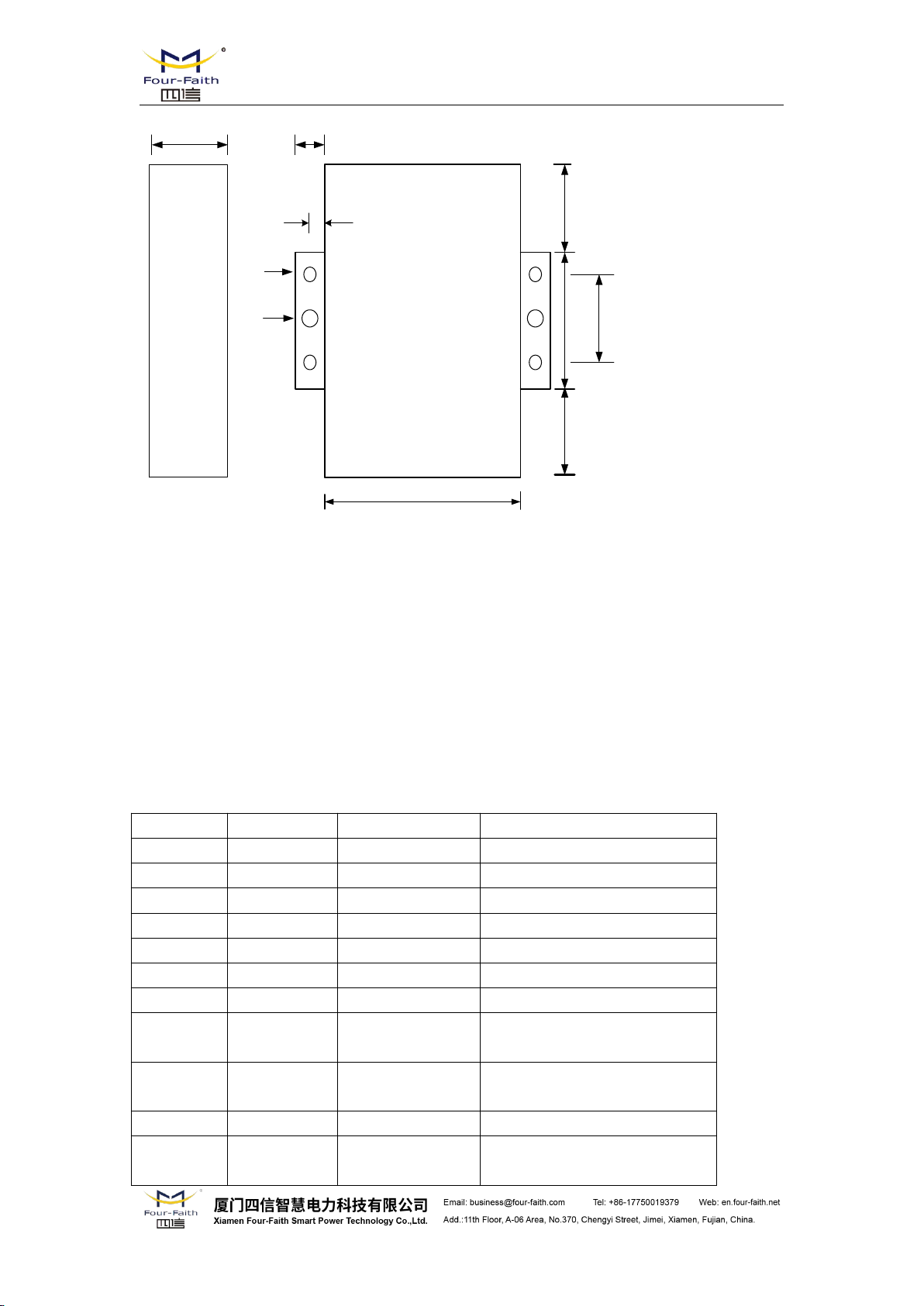
58.5
35
28
28
22
8
25
Ф3
Ф5
4
Figure 2-1 Installation Chart
Pin Number
Signal Name
Default Function
Extensible Function
1
PWR
Power input anode
N/A
2
GND
Power Ground
N/A
3
GND
Power Ground
N/A
4
RX
RS232 RX
N/A
5
TX
RS232 TX
N/A
6
A
RS485 anode
Reserved compatible DTR
7
B
RS485 cathode
Reserved compatible DSR
8
IO1
GPIO
Reserved compatible RTS and
RS232 RX (TTL logic level)
9
IO2
GPIO
Reserved compatible CTS and
RS232 TX (TTL logic level)
10
IO3
GPIO
Reserved compatible DCD
11
IO4
GPIO
Reserved compatible RI,ADC,
and pulse output
F8X14 Series User Manual
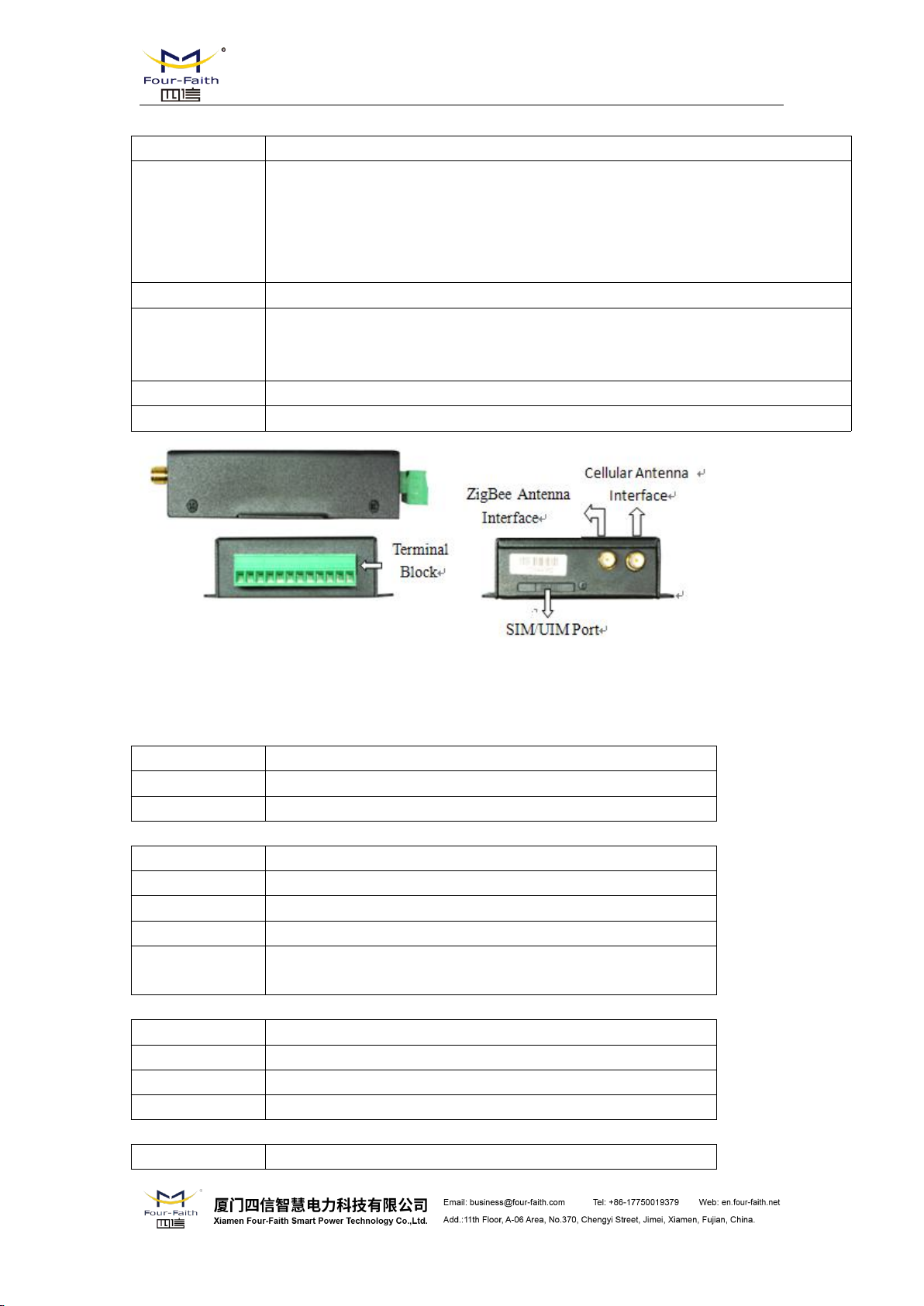
Installation of SIM/UIM card:
Firstly power off the IP MODEM, and press the out button of the SIM/UIM card outlet with a
needle object. Then the SIM/UIM card sheath will flick out at once. Put SIM/UIM card into the
card sheath (Pay attention to put the side which has metal point outside), and insert card sheath
back to the SIM/UIM card outlet.
Warning: Forbid to install SIM/UIM card when powered!
Installation of antenna:
Screw the SMA male pin of the antenna to the female SMA outlet of the IP MODEM tightly.
Warning: The antenna must be screwed tightly, or the signal quality of antenna will be influenced!
User Interface Signal Definition
F8X14 Series User Manual
12
IO5
GPIO
Reserved compatible pulse wave
input counter, ADC, and pulse
output
Cable Color
Power Output Polarity
Black &White Alternate
Anode
Black
Cathode
Cable Color
Corresponding DB9-M Pin Number
Brown
Pin 2
Blue
Pin 3
Black
Pin 5
Cable Color
Signal definition
Red
RS485(A)
Black
RS485(B)
Installation of cable:
F8X14 adopts industrial terminal block interface. The recommendatory cable is 28-16AWG.
The detail description of standard layout adapter and communication cables as is following:
Adapter(Rating Output 12VDC/0.5A):
RS232 Cable:
RS485 Cable:
Power adapter and communication cable connection chart as following:
Indicator
Light
State
Introduction
Power
ON
IP MODEM is powered on
OFF
IP MODEM is powered off
ACT
BLINK
Data is communicating
OFF
No data
Online
ON
IP MODEM has logged on network
OFF
IP MODEM hasn’t logged on network
ZigBee
ON
ZigBee Transport data
OFF
No data
Communication Interface: RS232
Communication Interface: RS485
F8X14 Terminal
Block Interface
User Device
(DB9M)
User Device
1
2
3
4
5
6
7
8
9
10
11
12
RX
GND
TX
A
B
IO1
IO2
IO3
IO4
PWR
GND
IO5
+ Anode
- Cathode
A
B
F8X14 Terminal
Block Interface
1
2
3
4
5
6
7
8
9
10
11
12
RX
GND
TX
A
B
IO1
IO2
IO3
IO4
PWR
GND
IO5
1
2
3
4
5
6
7
8
9
GND
TX
RX
+ Anode
- Cathode
RX
F8X14 Series User Manual
2.4 Power
The power range of the IP MODEM is DC 5~35V. When we use other power, we should make
sure that the power can supply power above 4W.
We recommend user to use the standard DC 12V/0.5A power adaptor.
2.5 Indicator Lights Introduction
The IP MODEM provides three indicator lights: “Power”, “ACT”, “Online”.
 Loading...