

Four-Faith F3936-3436H, F3936-3736H, F3936-3636H, F3936-3A36H, F3936-3836H User Manual

F3936-3X36H Series Router User Manual
The user manual is suitable for the following model:
F3936-3x36H Series
Router
User Manual
Documentation No. Product Version Page
V1.0
Product Name: F3936-3X36H Total:79
Model Product Type
F3936-3436H
WCDMA&HSDPA&HSUPA&HSPA+
ROUTER
F3936-3636H
CDMA2000 1X EVDO ROUTER
F3936-3736H
LTE&TD-SCDMA ROUTER
F3936-3836H
LTE&WCDMA ROUTER
F3936-3A36H
LTE&EVDO ROUTER

F3936-3X36H Series Router User Manual
Page2of
79
Files Revised Record
Date Version Remark Author
2014-9-28 V1.00 Initial version wonder
F3936-3X36H Series Router User Manual
Page3of
79

F3936-3X36H Series Router User Manual
Page4of
79
Contents
Contents
Chapter 1 Brief Introduction of Product............................................................................................. 6
1.1 General............................................................................................................................... 6
1.2 Features and Benefits......................................................................................................... 6
1.3 Working Principle...............................................................................................................9
1.4 Specifications................................................................................................................... 10
Chapter 2 Installation Introduction................................................................................................... 14
2.1 General............................................................................................................................. 14
2.2 Encasement List............................................................................................................... 14
2.3 Installation and Cable Connection...................................................................................14
2.4 Power................................................................................................................................17
2.5 Indicator Lights Introduction...........................................................................................17
2.6 Reset Button Introduction................................................................................................18
Chapter 3 Configuration and Management.......................................................................................19
3.1 Configuration Connection................................................................................................19
3.2 Access the Configuration Web Page................................................................................19
3.3 Management and configuration....................................................................................... 22
3.3.1 Setting.......................................................................................................................22
3.3.1.1 Basic Setting................................................................................................. 22
3.3.1.2 Dynamic DNS...............................................................................................29
3.3.1.3 Clone MAC Address.....................................................................................30
3.3.1.4 Advanced Router...........................................................................................30
3.3.1.5 VLANs..........................................................................................................32
3.3.1.6 Networking....................................................................................................33
3.3.2 Wireless....................................................................................................................36
3.3.2.1 Basic Settings................................................................................................36
3.3.2.2 Wireless Security...........................................................................................38
3.3.3 Services.................................................................................................................... 40
3.3.3.1 Services......................................................................................................... 40
3.3.3.2 USB...............................................................................................................43
3.3.3.3 FTP Server.....................................................................................................43
3.3.3.4 Hotspot..........................................................................................................44
3.3.4 Security.....................................................................................................................46
3.3.4.1 Firewall......................................................................................................... 46
3.3.5 Access Restrictions.................................................................................................. 48
3.3.5.1 WAN Access.............................................................................................. 48
3.3.5.2 Packet Filter.................................................................................................. 51
3.3.6 NAT.......................................................................................................................... 52
3.3.6.1 Port Forwarding............................................................................................ 52
3.3.6.2 Port Range Forward...................................................................................53
3.3.6.3 DMZ..............................................................................................................54
3.3.7 QoS Setting.............................................................................................................. 54
3.3.7.1 Basic..............................................................................................................54

F3936-3X36H Series Router User Manual
Page5of
79
3.3.7.2 Classify..........................................................................................................55
3.3.8 Applications..............................................................................................................56
3.3.8.1 Serial Applications.....................................................................................56
3.3.9 Administration..........................................................................................................57
3.3.9.1 Management..................................................................................................57
3.3.9.2 Keep Alive.....................................................................................................60
3.3.9.3 Commands.................................................................................................... 60
3.3.9.4 Factory Defaults............................................................................................61
3.3.9.5 Firmware Upgrade........................................................................................ 62
3.3.9.6 Backup...........................................................................................................62
3.3.10 Status......................................................................................................................63
3.3.10.1 Router..........................................................................................................63
3.3.10.2 WAN............................................................................................................65
3.3.10.3 LAN.............................................................................................................68
3.3.10.4 Wireless.......................................................................................................70
3.3.10.5 Device Management................................................................................... 72
3.3.10.6 Bandwidth................................................................................................... 73
3.3.10.7 Sys-Info.......................................................................................................74
Appendix........................................................................................................................................... 78
F3936-3X36H Series Router User Manual
Chapter 1 Brief Introduction of Product
1.1 General
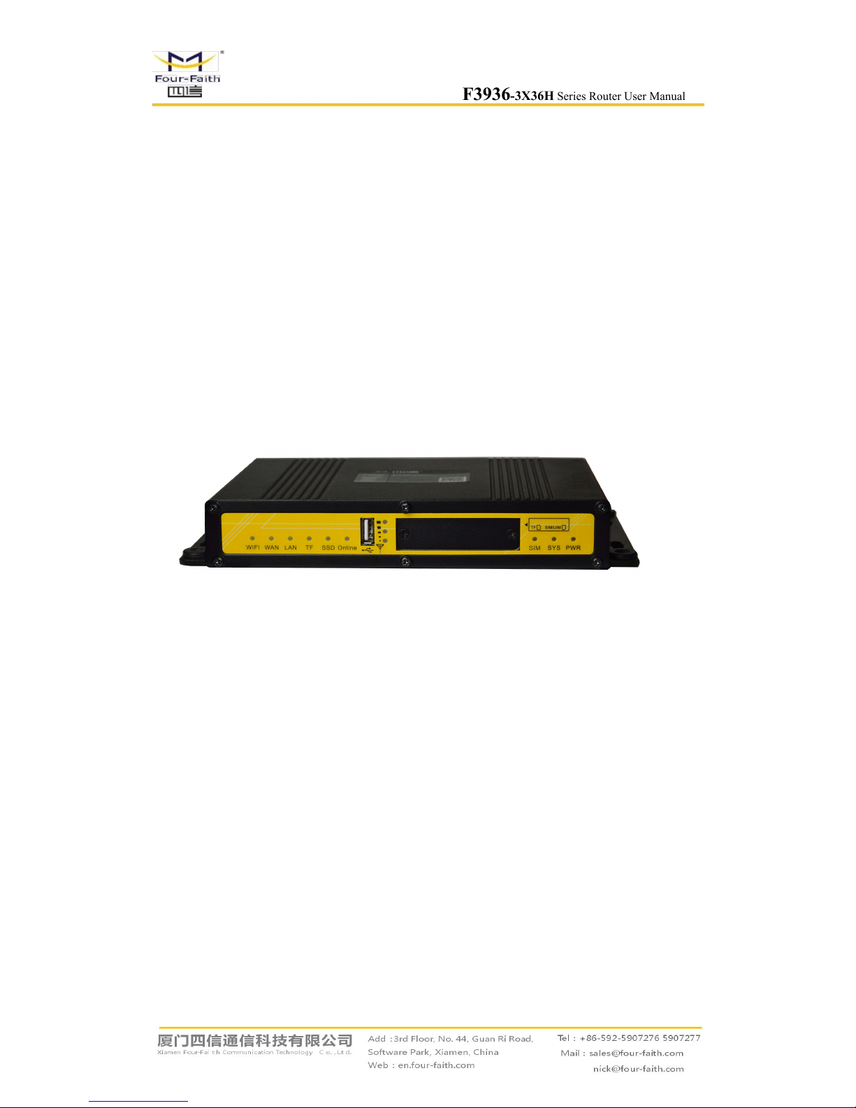
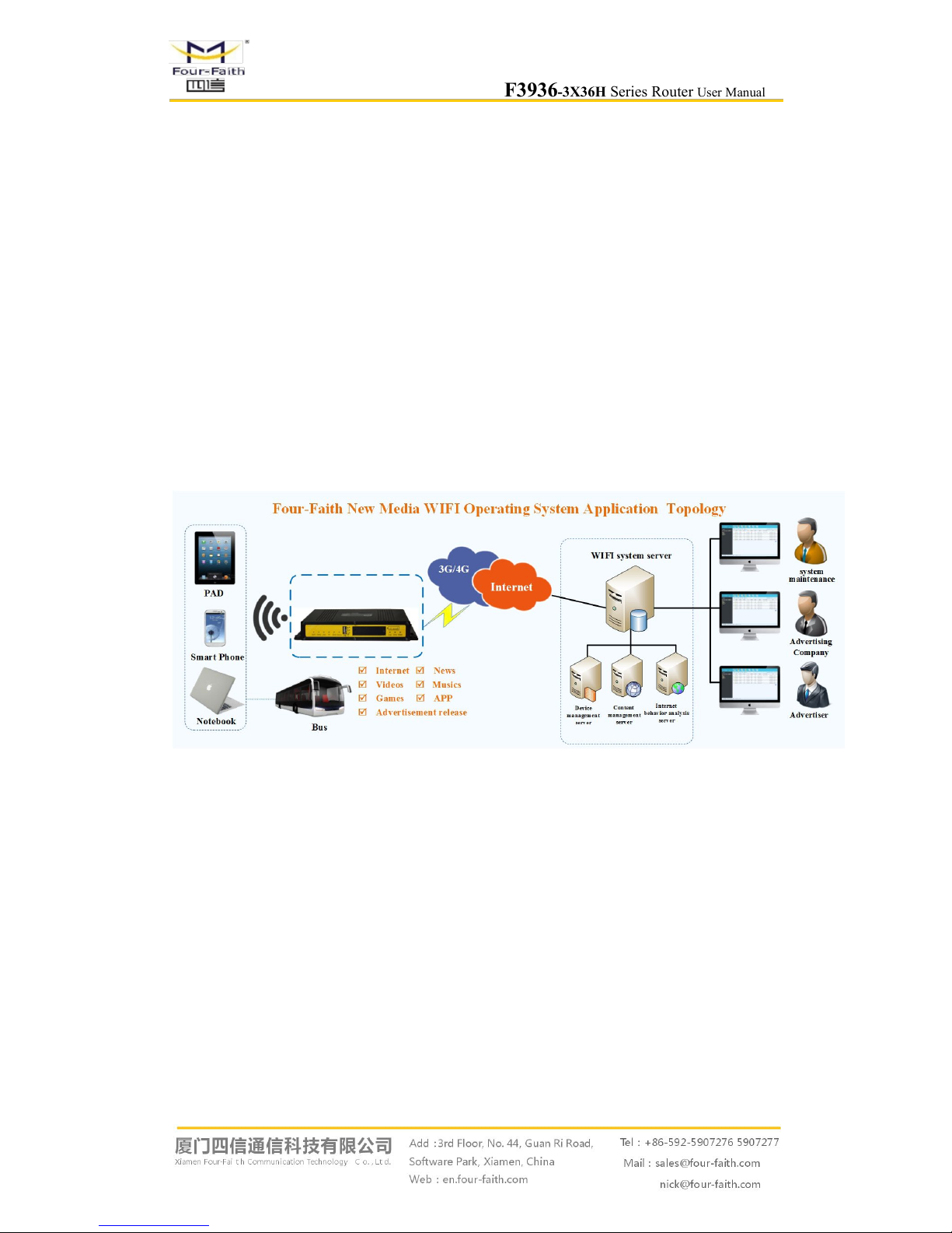
F3936-3x36H is a vehicle WIFI new media operating terminal and it integrates the advanced
3G/4G/WIFI communication technology, local large-capacity storage and multimedia advertising
push technology. The passengers can use smart phones, PAD and notebook to enjoy freely the
local videos, news, music, games, and quickly connecting the Internet, etc. And media operators
may carry out more value added services.
F3936-3A36H has been already widely used in public transportation, tourism, finance and
medical industries, such as urban public transport, customized bus, bus stations, tour bus,
long-distance passenger bus, tourist attractions, bank, hospital and so on.
1.2 Features and Benefits
Design for Vehicle Application
High-powered 32bits CPU
Vehicle power supply design, support under-voltage, over-voltage, over-current,
reverse connection, short circuit, surge protection
Wide Power range: DC 9~36V
Wide Operating Temperature(-35~+75ºC)
Aviation plug for power input
Metal shell, high heat radiating and anti collision performance
Shockproof design,suitable for vehicle vibrating environment
Security structure design for TF/SIM card

F3936-3X36H Series Router User Manual
Page 7 of 79
Stability and Reliability
Support hardware and software WDT to ensure the stability of the system
Support auto recovery mechanism, including online detect, auto redial when
offline to make router always online
Data storage with SSD, ensure the data security and stability on high speed read
and write
Ethernet port: 1.5KV magnetic isolation protection
RS232/RS485/RS422 port: 15KV ESD protection
SIM/UIM port: 15KV ESD protection
Antenna port: lightning protection(optional)
Standard and Convenience
Support all kinds of the Intelligent WIFI terminals
Smart data terminal, enter into communication state automatically when powered
Provides standard wired WAN port and wireless 3G/4G network interface
Small size device,rapid establishment of wireless network to use
Provide powerful business platform for equipment management, content
management and release, report management, user behavior statistics analysis,
authority management, alarm management, billing system (optional) and other
functions
High-performance
Support website redirection, local captive portal, remote captive portal(optional)
Support various authentication ways, including mobile phone number
authentication, Wechat authentication, Weibo authentication, QQ authentication
and without authentication.
Support WIFI channel hopping for anti-interference
Support English SSID
Support SSD(Solid State Disk) and TF card for local storage(TF card is optional)
WIFI TX power is configurable for optimized wireless coverage
Support WEB server. Supports PHP, XML, and database storage(optional)
Support WIFI inspector
Support black/white list of URL, accout, IP address, MAC address
Support traffic statistics. Support monitoring of device traffic, user traffic and
online duration monitoring.
Support user’s surfing behavior record, local PV/UV statistics and transmit these
data to server at real time for data statistics analysis.
Support real time log auditing based on user’s URL access
Local information contains advertisement, news, APP, video, music, etc. Support

F3936-3X36H Series Router User Manual
Page 8 of 79
various video formats and streaming media delivery
Local information update support whole update and incremental update, support
grouping update, support break-point resume and outage resume, support A/B
backup, support update via 3G/4G, FTP, station WIFI(optional) and USB
dongle(optional)
Support remote firmware upgrade, including upgrade on single device, devices in
patch and automatic upgrade(optional), support break-point resume, outage
resume(optional), support firmware upgrade with USB dongle(optional).
Support remote configuration, including configuration on single device, devices
in patch and custom configuration on both online and offline devices. support
firmware upgrade with USB dongle(optional).
Support monitoring device status at real time, including CPU, memory, signal
strength, network status, storage and alarm
Supports completed functionality of router
Support SPI firewall, access restriction, URL filter, QoS, NAT, etc
Support NTP, schedule reboot and schedule boot/shutdown with in built RTC
Support various WAN connection types, including static IP, DHCP, PPPoE, 3G /
4G, etc
Support 3G/4G network and Ethernet WAN for backup(optional)
Support VPN client and VPN server(PPTP, L2TP, OPENVPN, IPSEC and
GRE(only VPN version supports)
F3936-3X36H Series Router User Manual
Page 9 of 79
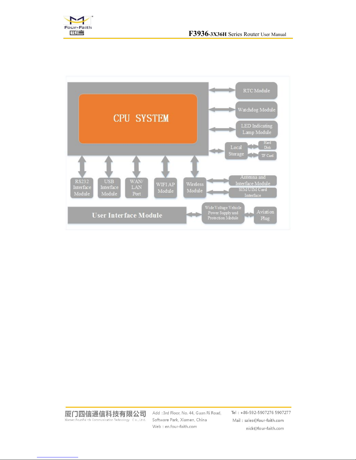
1.3 Working Principle
The principle chart of the router is as following:

F3936-3X36H Series Router User Manual
Page 10 of 79
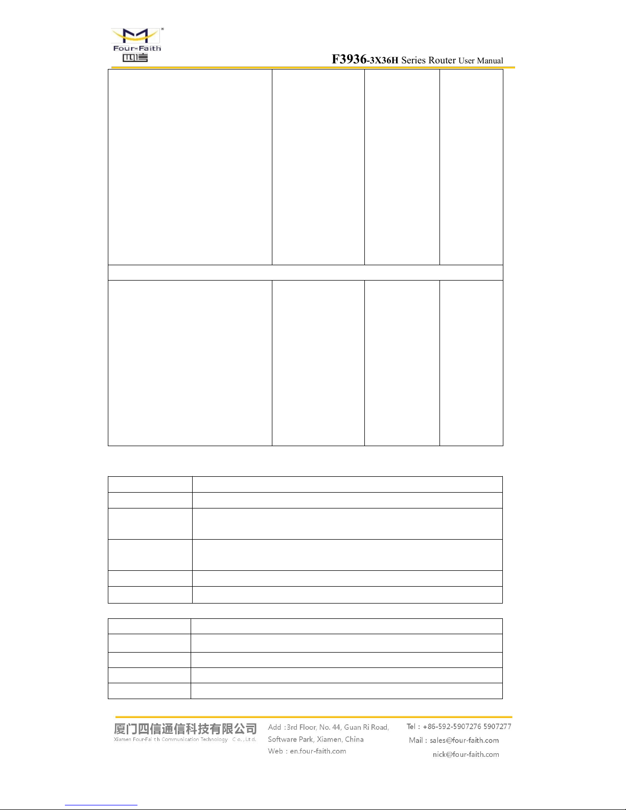
1.4 Specifications
Cellular Specification
Standard and Band Bandwidth TX power
RX
sensitivity
F3936-3436H WCDMA&HSDPA&HSUPA ROUTER
UMTS/WCDMA/HSDPA/HSUPA
/HSPA+ 850/1900/2100MHz
850/900/1900/2100MHz(optional)
GSM850/900/1800/1900MHz
GPRS/EDGE CLASS 12
HSUPA:5.76Mbps
(Upload speed)
HSDPA:7.2Mbps
(Download speed)
UMTS:384Kbps (DL/UL)
HSPA+:
21 Mbps
(Download speed)
5.76Mbps(Upload speed)
<24dBm <-109dBm
F3936-3636H CDMA2000 1X EVDO ROUTER
CDMA2000 1X EVDO Rev A
800MHz,800/1900MHz(optional)
450MHz (optional)
CDMA2000 1X RTT, IS-95 A/B
Download speed:3.1Mbps,
upload
speed:1.8Mbps;Rev
B(optional): Download
speed:14.7Mbps, upload
speed:5.4Mbps
<23dBm <-104dBm
F3936-3736H LTE/TD-SCDMA ROUTER
LTE TDD 2600/1900/2300MHz
(Band 38/39/40)
800/1400/1800MHz(Band27/61/62 )
(optional)
TD-SCDMA 2010/1900MHz ( A/F
frequency band,Band 34/39)
GSM/GPRS/EDGE
900/1800/1900MHz
LTE
TDD(Download
speed:68Mbps ,
upload
speed:17Mbps)
/TD-SCDMA :2.2
Mbps(upload
speed)/2.8Mbps(do
wnload speed)
<23dBm <-97dBm
F3936-3836H LTE/WCDMA ROUTER
LTE FDD
2600/2100/1800/900/800MHz(Band
1/3/7/8/20)
700/850/1700/1900/2100MHz (Band
2/4/5/13/17/25)(optional)
DC-HSPA+/HSPA+/HSDPA/
LTE
FDD(Download
speed:100Mbps ,
upload
speed:50Mbps)
/HSUPA:5.76Mbps(
<23dBm <-93.3dBm
F3936-3X36H Series Router User Manual
Page 11 of 79
HSUPA/WCDMA/UMTS
2100/1900/900/850/800MHz
(Band 1/2/5/6/8)
EDGE/GPRS/GSM
850/900/1800/1900MHz
upload speed)/
HSDPA:7.2Mbps(d
ownload speed:)
UMTS:384Kbps
(download
speed/upload
speed)
HSPA+:
42Mbps(download
speed)
5.76Mbps(upload
speed)
F3936-3A36H LTE&EVDO ROUTER
LTE FDD
700/850/1700/1900/2100MHz
(Band 2/4/5/13/17/25)
CDMA 1XRTT/EVDO
800/1900MHz
(Band Class 0/Class 1/Class 10)
LTE(Download
speed:100Mbps ,
upload
speed:50Mbps)
CDMA2000 1X
EVDO Rev A
(download
speed:3.1Mbps ,
upload
speed:1.8Mbps)
<23dBm <-93.3dBm
WIFI Specification
Item
Content
Standard
IEEE802.11b/g/n, 2.4G, 2*2 MIMO,AP model, Station model(optional)
Bandwidth
IEEE802.11b/g: 108Mbps (max)
IEEE802.11n: 300Mbps (max)
Security
WEP, WPA, WPA2, etc.
WPS (optional)
TX power
20dBm(11n),21.5dBm(11g),26dBm(11b)
RX sensitivity
<-75dBm@54Mpbs
Hardware System
Item Content
CPU High-performance 32bits CPU
FLASH 32MB(Extendable to 64MB)
DDR2 256MB
SSD 128GB(Extendable to 2TB)

F3936-3X36H Series Router User Manual
Page 12 of 79
TF 32GB(optional)
Interface Type
Item Content
WAN 1 10/100 Mbps WAN port(RJ45), auto MDI/MDIX, 1.5KV magnetic
isolation protection
LAN 1 10/100 Mbps Ethernet ports(RJ45), auto MDI/MDIX, 1.5KV magnetic
isolation protection
Serial
1 RS232(or RS485/RS422) port, 15KV ESD protection
Data bits: 8(optional 5, 6 ,7,)
Stop bits: 1, 1.5(optional), 2
Parity: none, even, odd, space(optional), mark(optional)
Baud rate: 2400~115200 bps
Indicator
“PWR”、“SYS”、“SIM”、“Online”、“SSD”、“TF”、“LAN”、“WAN”
、
“WIFI”, "Signal Strength"
Antenna
Cellular: Standard SMA female interface, 50 ohm, lighting
protection(optional)
WIFI: standard SMA male interface, 50 ohm, lighting protection(optional)
SIM/UIM Standard 3V/1.8V user card interface, 15KV ESD protection
USB Standard A type USB host interface,support USB 2.0 High-speed
TF Standard TF card interface
Power Aviation plug
Reset Restore the router to its original factory default settings

F3936-3X36H Series Router User Manual
Page 13 of 79
Power Supply
Item Content
Standard Power DC 12V/1.5A
Power range DC 9~36V
Working current 3G:<750mA (12V) 4G:<850mA (12V)
Standby current 3G:<550mA (12V) 4G:<500mA (12V)
Physical Characteristics
Item Content
Housing
Metal shell, shock proof design, suitable for vehicle vibrating
environment
Dimensions 244x139x36 mm
Weight 940g
Other Specification
Item Content
Operating
Temperature
-35~+75ºC(-31~+167℉)
Storage
Temperature
-40~+85ºC (-40~+185℉)
Operating
Humidity
95% ( unfreezing)
Antenna Photograph
3G/4GAntenna
2.4/5.8G WIFI Antenna

F3936-3X36H Series Router User Manual
Page 14 of 79
Chapter 2 Installation Introduction
2.1 General
The F3936-3X36H must be installed correctly to make it work properly.
Warning: Forbid to install the router when powered!
2.2 Encasement List
Name Quantity Remark
F3936-3X36H host 1
Cellular antenna (Male SMA) 1(Note 1)
WIFI antenna (Female SMA) 2
Network cable 1
Console cable 1 optional
Power adapter 1 optional
Manual CD 1
Certification card 1
Maintenance card 1
Note1:Cellular antenna (Male SMA) 1 pcs for 3G device and 2 pcs for 4G device
2.3 Installation and Cable Connection
Dimension(unit:mm):

F3936-3X36H Series Router User Manual
Page 15 of 79
Installation of SIM/UIM card:
For the SIM/UIM card installation,the following is the operation guide.
1,Remove the iron plate off with the screwdriver.
2,Press the out button of the SIM/UIM card outlet with a needle object.Then the SIM/UIM
card sheath will flick out at once.
3,Put SIM/UIM card into the card sheath. (Pay attention to put the side which has metal point
outside).
4,Insert card sheath back to the SIM/UIM card outlet
5, Screw the iron plate tightly.
Warning: Forbid to install SIM/UIM card when powered!
Installation of antenna:
Screw the SMA male pin of the cellular antenna to the female SMA interface of the router
with sign “ANT”.
Screw the SMA female pin of the WIFI antenna to the male SMA interface of the router with
sign “WIFI”.
Warning: The cellular antenna and the WIFI antenna can not be connected wrongly. And the
antennas must be screwed tightly, or the signal quality of antenna will be influenced!The WIFI
antenna must be two!
Installation of cable:
Insert one end of the network cable into the switch interface with sign “LAN”, and insert the
other end into the Ethernet interface of user’s device. The signal connection of network direct

F3936-3X36H Series Router User Manual
Page 16 of 79
cable is as follows:
RJ45-1 RJ45-2
1 1
2 2
3 3
4 4
5 5
6 6
7 7
8 8
Insert the RJ45 end of the console cable into the RJ45 outlet with sign “console”, and insert
the DB9F end of the console cable into the RS232 serial interface of user’s device.
The signal connection of the console cable is as follows:
RJ45 DB9F
1 8
2 6
3 2
4 1
5 5
6 3
7 4
8 7
The signal definition of the DB9F serial communication interface is as follows:
Pin RS232 signal name The direction for Router
1 DCD output
2 RXD output
3 TXD input
4 DTR input
5 GND
6 DSR output
7 RTS input
8 CTS output
F3936-3X36H Series Router User Manual
Page 17 of 79
2.4 Power
The F3936-3X36H is usually used in complex external environment. In order to adapt to the
complex application environment and improve the working stability,the F3936-3X36H adopt the
advanced power solution.
The power range of the router is DC 9~36V.
Warning: When we use other power, we should make sure that the power can supply power
above 7W,power ripple is less then 300mV.
We recommend user to use the standard DC 12V/1.5A power.
2.5 Indicator Lights Introduction
The F3936-3X36H provides following indicator lights: “PWR”, “SYS”, “SIM”,“Online”,
“SSD”, “TF”, “LAN”,“WAN”, “WIFI”, “Signal Strength”.
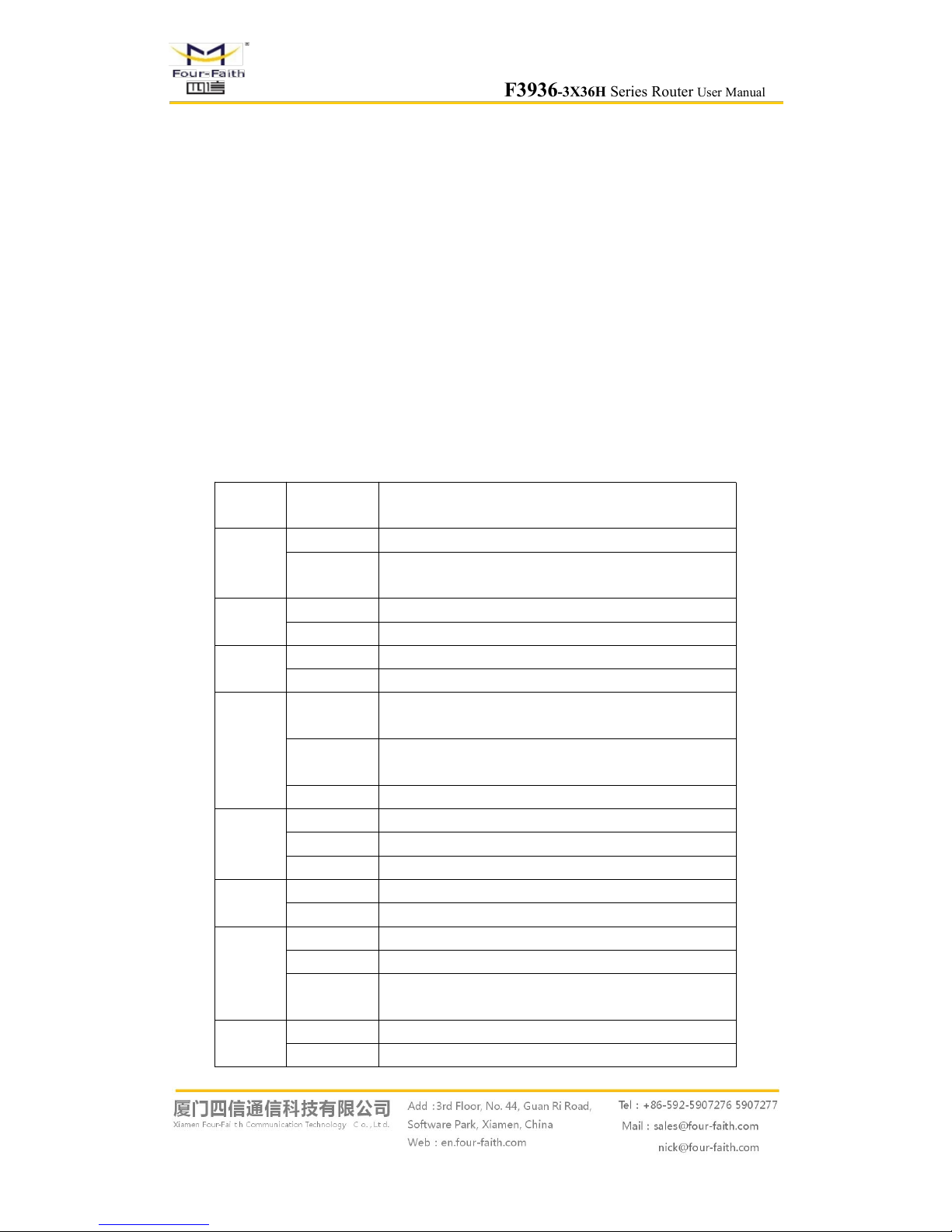
Indicator
Light
State Introduction
PWR
ON Router is powered on
OFF
Router is powered off or in the shutdown period of
schedule boot&shutdown
System
BLINK System works properly
OFF System does not work
SIM
ON Identify the SIM Card
OFF Not identify the SIM Card
Online
ON
Router has connected the internet and logged on the
service platform
BLINK
Router has connected the internet but not logged on the
service platform
OFF Router has not connected the internet
SSD
ON Router has detected the SSD
BLINK SSD is reading/writing
OFF Router has not detected the SSD
TF
ON Router has detected the TF Card
OFF Router has not detected the TF Card
LAN
OFF The interface of LAN is not connected
BLINK The interface of LAN is communicating
ON /
BLINK
The interface of LAN is connected
WAN
OFF The interface of WAN is not connected
BLINK The interface of WAN is connected /Communicating

F3936-3X36H Series Router User Manual
Page 18 of 79
ON /
BLINK
The interface of WAN is communicating
WIFI
OFF WIFI is not active
ON WIFI is active
Signal
Strength
One Light
ON
Signal strength is weak
Two Lights
ON
Signal strength is medium
Three
Lights ON
Signal strength is good
2.6 Reset Button Introduction
The F3936-3X36H has a “RST” button to restore it to its original factory default settings.
When user press the “RST” button for up to 20s, the router will restore to its original factory
default settings and restart automatically.(The “SYS” LED is power off for 10s and blink again
indicate the restart complete)
F3936-3X36H Series Router User Manual
Page 19 of 79
Chapter 3 Configuration and Management
This chapter describes how to configure and manage the router.
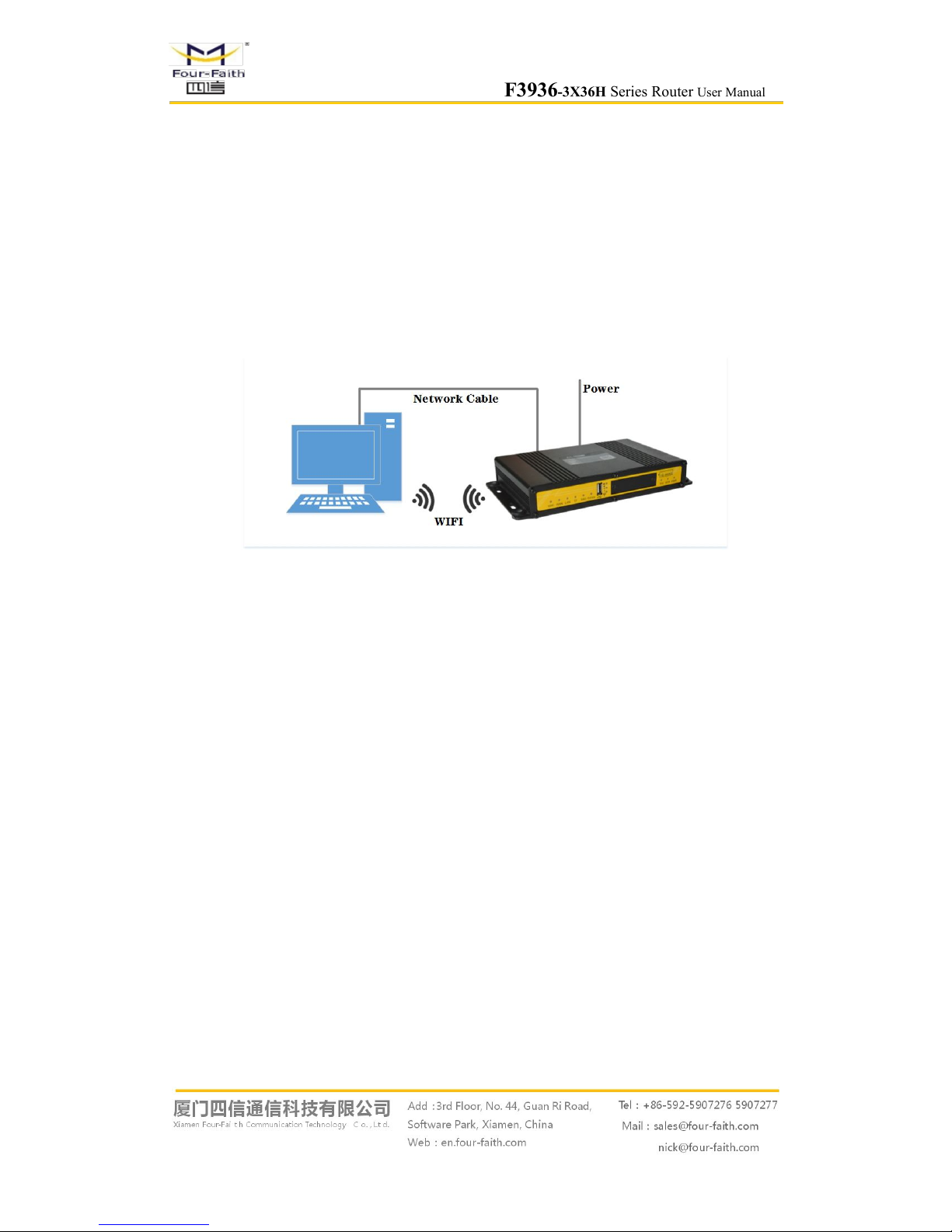
3.1 Configuration Connection
Before configuration, you should connect the router and your configuration PC with the
supplied network cable. Plug the cable’s one end into the Local Network port of the router, and
another end into your configure PC’s Ethernet port. The connection diagram is as following:
Please modify the IP address of PC as the same network segment address of the router, for
instance, 192.168.1.9. Modify the mask code of PC as 255.255.255.0 and set the default gateway
of PC as the router’s IP address (192.168.1.1).
3.2 Access the Configuration Web Page
The chapter is to present main functions of each page. Users visit page tool via web browser
after connect users' PC to the router. There are eleven main pages: Setting, Wireless, Service, VPN,
Security, Access Restrictions, NAT, QoS Setting, Applications, Management and Status. Users
enable to browse slave pages by click one main page..
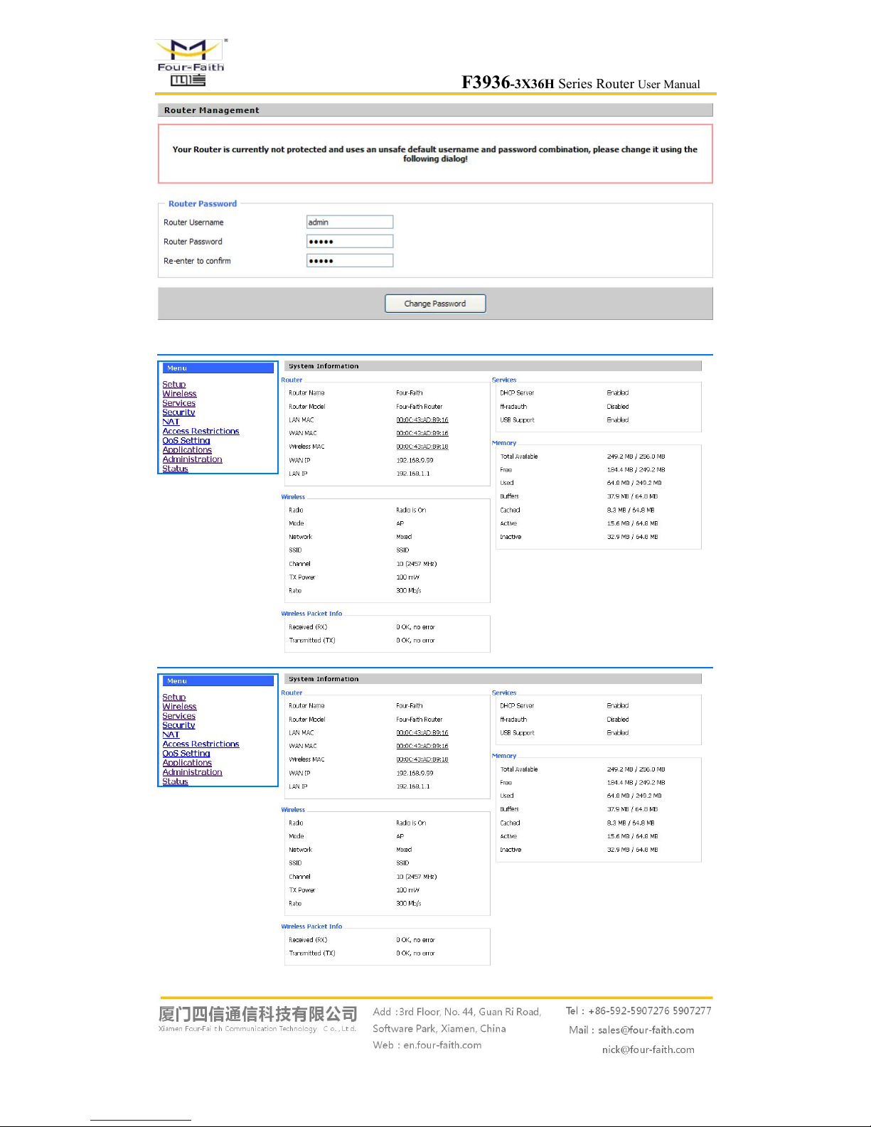
Users can open IE or other explorers and enter the router's default IP address of
192.168.1.1:90 on address bar, then press the botton of Enter to visit page Web management tool
of the router. The users login in the web page at the first name, there will display a page shows as
blow to tip users to modify the default user name and password of the router. Users have to click
"change password" to make it work if they modify user name and password.
F3936-3X36H Series Router User Manual
Page 20 of 79
After access to the information main page
F3936-3X36H Series Router User Manual
Page 21 of 79
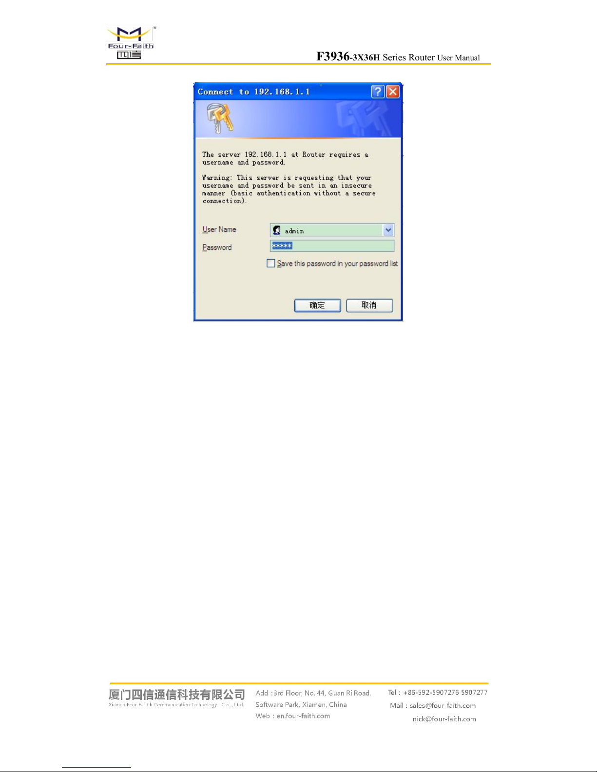
Users need to input user name and password if it is their first time to login.
Input correct user name and password to visit relevant menu page. Default user name is admin,
password is admin. (available to modify user name and password on management page, then click
submit)
F3936-3X36H Series Router User Manual
Page 22 of 79
3.3 Management and configuration
3.3.1 Setting
The Setup screen is the first screen users will see when accessing the router. Most users will be
able to configure the router and get it work properly using only the settings on this screen. Some
Internet Service Providers (ISPs) will require users to enter specific information, such as User
Name, Password, IP Address, Default Gateway Address, or DNS IP Address. These information
can be obtained from your ISP, if required.
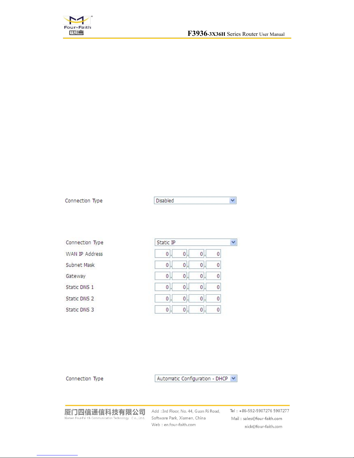
3.3.1.1 Basic Setting
WAN Connection Type
Six Ways: Disabled, Static IP, Automatic DHCP, PPPOE, 3G/UNMTS/4G/LTE,dhcp-4G.
Disabled
Forbid the setting of WAN port connection type
Static IP
WAN IP Address: Users set IP address by their own or ISP assigns
Subnet Mask: Users set subnet mask by their own or ISP assigns
Gateway: Users set gateway by their own or ISP assigns
Static DNS1/DNS2/DNS3: Users set static DNS by their own or ISP assigns
Automatic Configuration-DHCP
IP address of WAN port gets automatic via DHCP
F3936-3X36H Series Router User Manual
Page 23 of 79
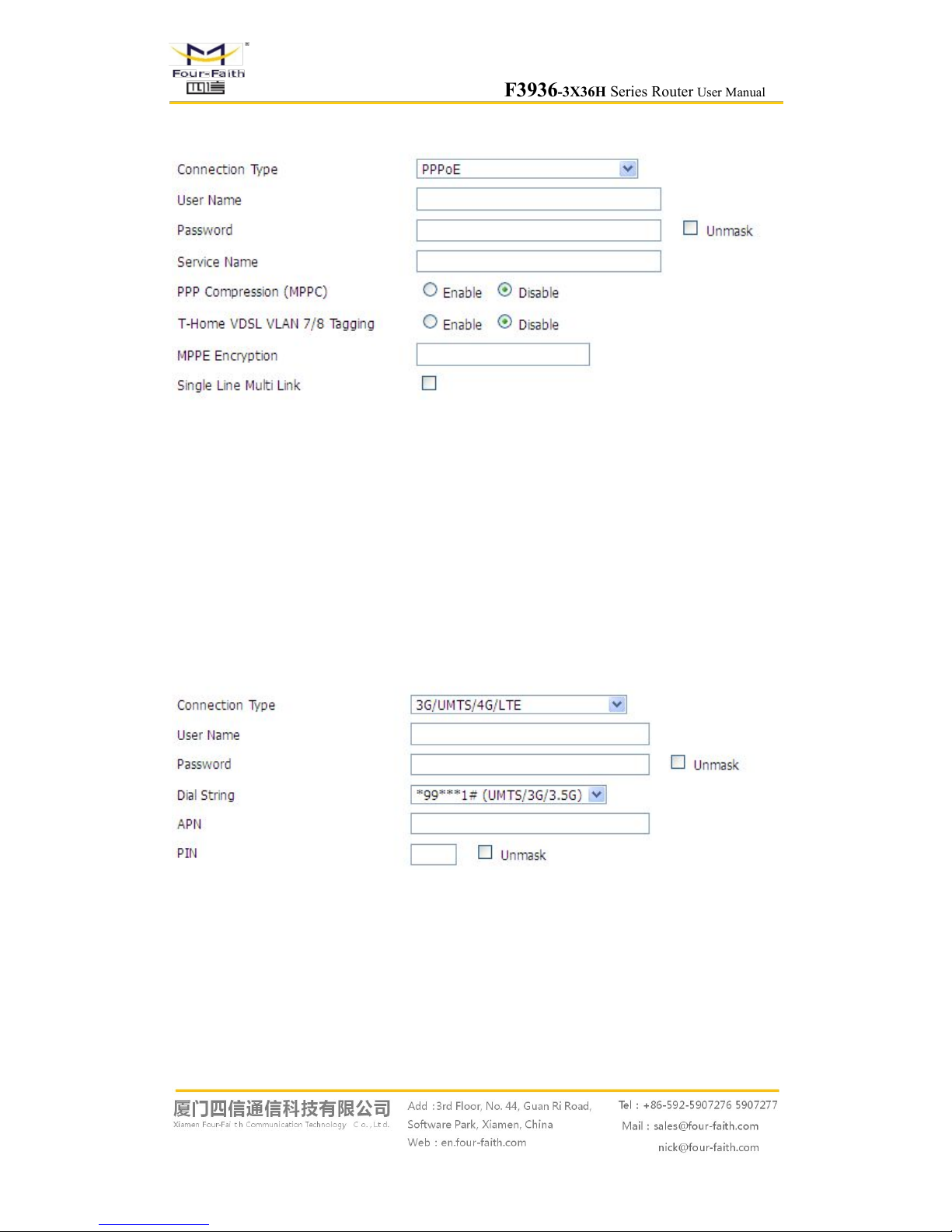
PPPOE
User Name: login the Internet
Password: login the Internet
Service Name: provided by ISP server, if not, keep it null
PPP Compression (MPPC): provides a method to negotiation and use of compressed in PPP
encapsulation link protocol
T-Home VDSL VLAN 7/8 Tagging: enable to support the front of the modem is vdsl
MPPE Encryption: Microsoft point to point encryption. It is used to encrypt the point-to-point
link connection agreement of the encrypted data packet
Single Line Multi Link: enable single line link or disable multi link
3G/UMTS/4G/LTE
User Name: login users' ISP(Internet Service Provider)
Password: login users' ISP
Dial String: dial number of users' ISP
APN: access point name of users' ISP
PIN: PIN code of users' SIM card
Connection type

F3936-3X36H Series Router User Manual
Page 24 of 79
Connection type: Auto, Force 3G, Force 2G, Prefer 3G, Prefer 2G options. If using 4G module,
there has 4G network option. Users select different mode depending on their need
Keep Online
This function is used to detect whether the Internet connection is active, if users set it and when
the router detect the connection is inactive, it will redial to users' ISP immediately to make the
connection active.
Detection Method:
None: do not set this function
Ping: Send ping packet to detect the connection, when choose this method, users should also
configure "Detection Interval", "Primary Detection Server IP" and "Backup Detection
Server IP" items.
Route: Detect connection with route method, when choose this method, users should also
configure "Detection Interval", "Primary Detection Server IP" and "Backup Detection
Server IP" items.
PPP: Detect connection with PPP method, when choose this method, users should also
configure "Detection Interval" item.
Detection Interval: time interval between two detections, unit is second
Primary Detection Server IP: the server used to response the router’s detection packet. This item
is only valid for method "Ping" and "Route".
Backup Detection Server IP: the server used to response the router’s detection packet. This item
is valid for method "Ping" and "Route".
Note: When users choose the “Route” or “Ping” method, it’s quite important to make sure
that the “Primary Detection Server IP” and “Backup Detection Server IP” are usable and stable,
because they have to response the detection packet frequently.
Connection Strategy
Connection Strategy: one way is Connect on Demand, that is the link turnoff automatic under the
situation that the ready link is idle and idle time meets users' configuration requirement, but tit will
connect again if users visit Internet. The other way is to keep alive, that is the link enable to dial
 Loading...