

Four-Faith F2164, F2264, F2464 User Manual

F2X64 Series
User Manual
Product Version
Page
V1.4
Product Name:F2X64
Total:98
F2X64 Series User Manual
The user manual is suitable for the following model:
Model
Product Type
F2164
GPRS RTU
F2264
CDMA RTU
F2464
WCDMA RTU
Xiamen Four-Faith Communication Technology Co., Ltd.
Add:J1-J3,3rd Floor,No.44,GuanRi Road,SoftWare
Park,XiaMen,China Zip Code:361008
Tel:+86 592-6300326,6300325,6300324
Fax:+86 592-5912735
http://www.fourfaith.com

F2X64 User Manual
Xiamen Four-Faith Communication Technology Co.,Ltd. Page 2 of 98
Add: J1-J3,3rdFloor,No.44,GuanRiRoad,SoftWare Park,XiaMen .361008.China
http://www.fourfaith.com Tel: +86 592-6300326 6300325 6300324 Fax:+86 592-5912735
Files Revised Record
Date
Version
Remark
Author
2012-11-20
V1.1
1. Delete setting by simple command of SMS
2. Delete and modify some parameter settings
Xingfa.lin
2012-12-25
V1.2
1. Modify acqisition interval
Xingfa.lin
2013-4-1
V1.2
Date input voltage
Lynn Zhu
2014-1-3
V1.3
1. Add the sms command to read input value
2. Add the sms command to control output
Xingfa.lin
2015-5-28
V1.4
1. Add ADC sample type description
ZXZ

F2X64 User Manual
Xiamen Four-Faith Communication Technology Co.,Ltd. Page 3 of 98
Add: J1-J3,3rdFloor,No.44,GuanRiRoad,SoftWare Park,XiaMen .361008.China
http://www.fourfaith.com Tel: +86 592-6300326 6300325 6300324 Fax:+86 592-5912735
Copyright Notice
All contents in the files are protected by copyright law, and all copyrights are reserved by Xiamen
Four-Faith Communication Technology Co., Ltd. Without written permission, all commercial
use of the files from Four-Faith are forbidden, such as copy, distribute, reproduce the files, etc.,
but non-commercial purpose, downloaded or printed by individual (all files shall be not revised,
and the copyright and other proprietorship notice shall be reserved) are welcome.
Trademark Notice
Four-Faith 、 四 信 、 、 、 are all registered trademarks of Xiamen
Four-Faith Communication Technology Co., Ltd., illegal use of the name of Four-Faith,
trademarks and other marks of Four-Faith is forbidden, unless written permission is authorized in
advance.
F2X64 User Manual
Xiamen Four-Faith Communication Technology Co.,Ltd. Page 4 of 98
Add: J1-J3,3rdFloor,No.44,GuanRiRoad,SoftWare Park,XiaMen .361008.China
http://www.fourfaith.com Tel: +86 592-6300326 6300325 6300324 Fax:+86 592-5912735

User Manual
Xiamen Four-Faith Communication Technology Co.,Ltd. Page 5 of 98
Add: J1-J3,3rdFloor,No.44,GuanRiRoad,SoftWare Park,XiaMen .361008.China
http://www.fourfaith.com Tel: +86 592-6300326 6300325 6300324 Fax:+86 592-5912735
Contents
Contents...............................................................................................................................................5
Chapter 1 Brief Introduction of Product............................................................................................. 9
1.1 General.................................................................................................................................. 9
1.2 Features and Benefits............................................................................................................9
1.3 Working Principle................................................................................................................11
1.4 Specifications...................................................................................................................... 12
Chapter 2 Installation Introduction................................................................................................... 14
2.1 General................................................................................................................................ 14
2.2 Encasement List.................................................................................................................. 14
2.3 Installation and Cable Connection......................................................................................14
2.4 Power...................................................................................................................................19
2.5 Indicator Lights Introduction.............................................................................................. 19
Chapter 3 RTU Function Introduction........................................................................................... 20
3.1 Multiple servers funticon.................................................................................................... 20
3.2 MODBUS protocol............................................................................................................. 20
3.2.1 MODBUS settings................................................................................................... 20
3.2.2 TCP2COM description............................................................................................ 21
3.2.3 MODBUS digital IO input introduction.................................................................. 21
3.2.4 MODBUS digital IO output introduction................................................................ 22
3.2.5 MODBUS read digital IO output introduction........................................................ 22
3.2.6 MODBUS counter introduction...............................................................................23
3.2.7 MODBUS analog input introduction.......................................................................25
3.3 RTU extended protocol....................................................................................................... 26
3.4 Alarm function.....................................................................................................................27
3.5 Multiply configure parameters............................................................................................27
3.6 Remote upgrade firmware...................................................................................................27
Chapter 4 Configuration....................................................................................................................28
4.1 RS232/RS485 Configuration.............................................................................................. 28
4.1.1 Configuration introduction.......................................................................................28
4.1.2 Run the configure tool..............................................................................................29
4.1.3 Re-power RTU......................................................................................................... 30
4.1.4 Configuration........................................................................................................... 31
4.1.4.1 Digital channel settings.................................................................................31
◆ Digital input function..................................................................................31
◆ MODBUS logic corresponding function....................................................32
◆ Acquisition purpose.................................................................................... 32
◆ Acquisition interval.....................................................................................32
◆ Alarm trigger condition...............................................................................33

User Manual
Xiamen Four-Faith Communication Technology Co.,Ltd. Page 6 of 98
Add: J1-J3,3rdFloor,No.44,GuanRiRoad,SoftWare Park,XiaMen .361008.China
http://www.fourfaith.com Tel: +86 592-6300326 6300325 6300324 Fax:+86 592-5912735
◆ Alarm content..............................................................................................33
◆ Alarm phone number...................................................................................33
4.1.4.2 Optocoupler and relay settings..................................................................... 34
◆ Digital output function................................................................................34
◆ MODBUS logic 1 output............................................................................ 35
◆ MODBUS logic 0 output............................................................................ 35
◆ MODBUS logic 1 square-wave cycle.........................................................35
◆ MODBUS logic 0 square-wave cycle.........................................................36
◆ Default output voltage.................................................................................36
4.1.4.3 Analog channel settings................................................................................ 37
◆ Analog input function................................................................................. 37
◆ Set sensor range.......................................................................................... 37
◆ Set sensor voltage or current output........................................................... 39
◆ MODBUS function..................................................................................... 40
◆ Acqisition function......................................................................................40
◆ Acqisition interval.......................................................................................40
◆ Alarm trigger condition...............................................................................40
◆ Alarm content..............................................................................................41
◆ Alarm phone number...................................................................................41
◆ Active report function................................................................................. 42
.4.1.4.4 RTU counter、report、Alarm settings.................................................... 42
◆ Counter function......................................................................................... 43
◆ Counter work mode.....................................................................................43
◆ Counter initial value....................................................................................43
◆ Alarm function............................................................................................ 43
◆ Alarm content..............................................................................................44
◆ Alarm phone number...................................................................................44
◆ Alarm upper limit........................................................................................44
◆ Active report interval.................................................................................. 45
◆ Alarm report method...................................................................................45
◆ Continuous alarm interval...........................................................................45
◆ Continuous alarm number of times.............................................................46
◆ Alarm administrator number.......................................................................46
4.1.4.5 ModBus Setting............................................................................................ 47
◆ ModBus work mode....................................................................................47
◆ ModBus address..........................................................................................48
◆ RTU work mode..........................................................................................48
4.1.4.6 Data Service Center Settings........................................................................ 49
◆ Data Center Number................................................................................... 49
◆ Main Center Addr+Port:............................................................................. 50
◆ Backup Center Addr+Port:..........................................................................50
◆ Multi DSC Configuration........................................................................... 51

User Manual
Xiamen Four-Faith Communication Technology Co.,Ltd. Page 7 of 98
Add: J1-J3,3rdFloor,No.44,GuanRiRoad,SoftWare Park,XiaMen .361008.China
http://www.fourfaith.com Tel: +86 592-6300326 6300325 6300324 Fax:+86 592-5912735
◆ Main and Backup Center DNS Server........................................................52
◆ Center 2~5 DNS Server.............................................................................. 52
4.1.4.7 Device Settings............................................................................................. 53
◆ Work Mode..................................................................................................53
◆ Trigger Type................................................................................................54
◆ Disconnect to Trigger mode........................................................................54
◆ Debug Level................................................................................................54
◆ Databit, Parity, Stopbit................................................................................55
◆ Communication Baudrate........................................................................... 55
◆ Auto Back To Main Server......................................................................... 56
◆ Device ID.................................................................................................... 56
◆ SIM Card No...............................................................................................56
◆ Bytes Interval.............................................................................................. 57
◆ Custom Register String...............................................................................57
◆ Custom Heartbeat String.............................................................................57
◆ Reconnect setting........................................................................................ 58
◆ Transfer meanning...................................................................................... 58
4.1.4.8 Other Settings................................................................................................59
◆ Network.......................................................................................................59
◆ SMS Center.................................................................................................60
◆ Heartbeat Interval........................................................................................60
◆ Call Trigger Phone No................................................................................ 61
◆ SMS Trigger Password............................................................................... 61
◆ Data Trigger Password................................................................................61
◆ TCP MTU....................................................................................................62
◆ Multi Center Reconnect Interval................................................................ 62
◆ Set parameter of configure SMS.................................................................62
4.1.4.9 Scheduled Power ON/OFF Setting...............................................................63
◆ RTC(Real Time Clock) Time Setting......................................................... 63
◆ Power On/Off Setting................................................................................. 64
4.1.4.10 SMS Setting................................................................................................ 73
◆ Destination number.....................................................................................73
◆ SMS Sending Format..................................................................................74
◆ Data upload Style........................................................................................74
4.1.4.11 Functions..................................................................................................... 75
◆ Show Configure.......................................................................................... 75
◆ Show Baudrate............................................................................................ 75
◆ Auto Detect................................................................................................. 75
◆ Version Display...........................................................................................75
◆ Signal Value................................................................................................ 75
◆ Factory setting.............................................................................................76
◆ Clear Output................................................................................................76

User Manual
Xiamen Four-Faith Communication Technology Co.,Ltd. Page 8 of 98
Add: J1-J3,3rdFloor,No.44,GuanRiRoad,SoftWare Park,XiaMen .361008.China
http://www.fourfaith.com Tel: +86 592-6300326 6300325 6300324 Fax:+86 592-5912735
◆ Save Output.................................................................................................76
◆ Browse.........................................................................................................76
◆ Save Configure............................................................................................76
◆ Load Configure........................................................................................... 76
4.1.5 Work State Switch....................................................................................................77
4.2 Setting by SMS................................................................................................................... 77
4.2.1 Setting by AT command of SMS............................................................................. 77
4.2.2 setting remote upgrade.............................................................................................78
4.2.3 Read digital IO input................................................................................................78
4.2.4 Control digital IO output..........................................................................................78
4.2.5 Read analog input.....................................................................................................79
4.3 Setting for RTU extended protocol.....................................................................................79
Chapter 5 Software Manual.............................................................................................................. 80
5.1 TCP2COM manual..............................................................................................................80
5.1.1 Open software.......................................................................................................... 80
5.1.2 Install the driver....................................................................................................... 80
5.1.3 Add virtual serial port.............................................................................................. 82
5.1.4 Setting the server parameters...................................................................................84
5.1.5 Server connection state............................................................................................ 84
5.1.6 Monitor.....................................................................................................................85
5.1.7 Not transmited data query........................................................................................86
5.1.8 Delete database data.................................................................................................87
5.1.9 Quit...........................................................................................................................88
5.2 RTU center service..............................................................................................................88
5.2.1 Open software.......................................................................................................... 88
5.2.2 Service setting..........................................................................................................89
5.2.3 Start equipment and connect....................................................................................89
5.2.4 View the acquisition data.........................................................................................90
5.2.5 Send data to RS232/RS485......................................................................................90
5.2.6 Control optocoupler and relay................................................................................. 91
5.2.7 Alarm information....................................................................................................91
5.2.8 Center service information.......................................................................................91
5.2.9 Query data................................................................................................................92
5.2.10 Remote configure...................................................................................................93
5.2.11 Upgrade.................................................................................................................. 93
5.2.12 Reset device........................................................................................................... 94
Appendix........................................................................................................................................... 96

User Manual
Xiamen Four-Faith Communication Technology Co.,Ltd. Page 9 of 98
Add: J1-J3,3rdFloor,No.44,GuanRiRoad,SoftWare Park,XiaMen .361008.China
http://www.fourfaith.com Tel: +86 592-6300326 6300325 6300324 Fax:+86 592-5912735
Chapter 1 Brief Introduction of Product
1.1 General
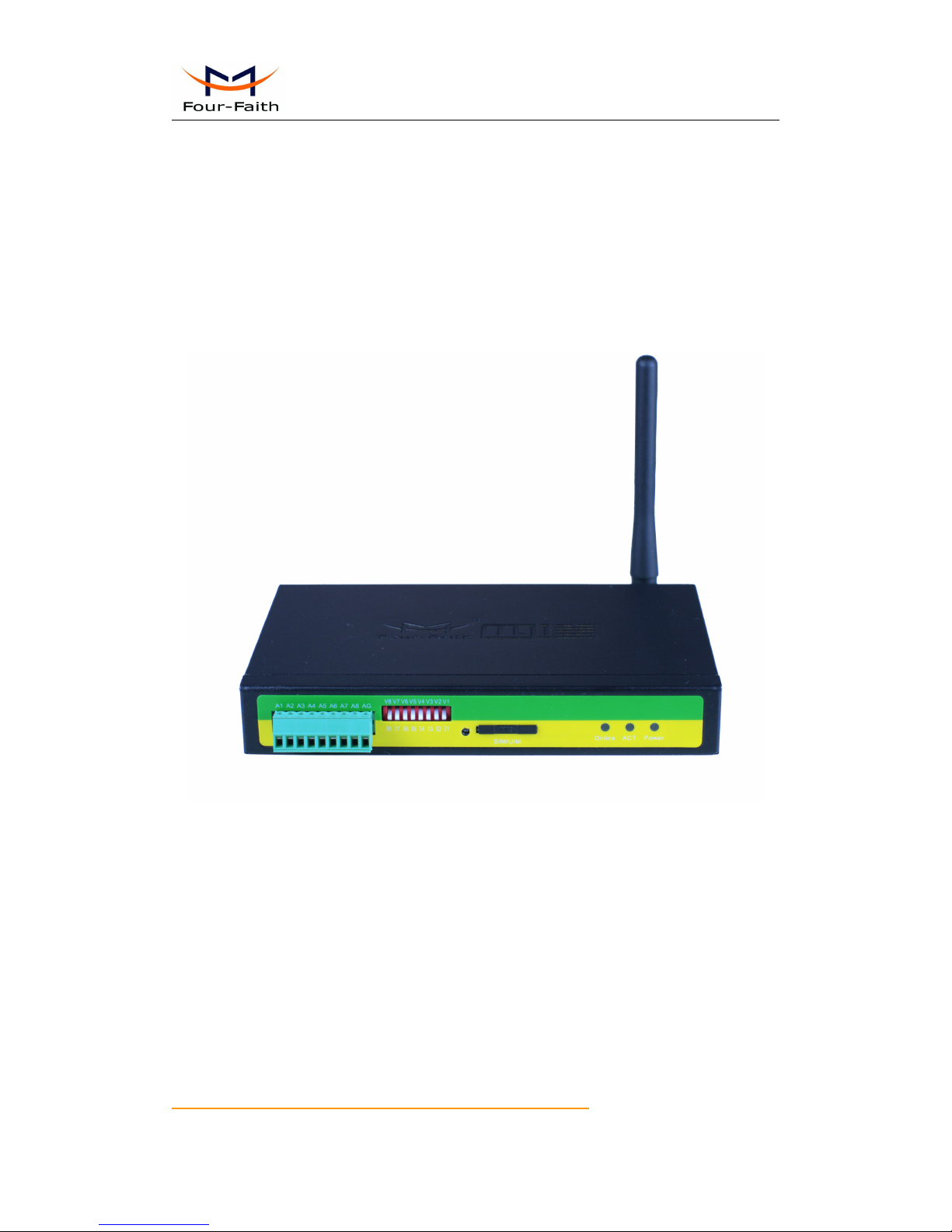
F2x64 series is wireless remote terminal unit(abbreviation:RTU). RTU has many functions
(analog input、switch input、switch output、pulse counting and wireless data communication ect).
It adopts high-powered industrial 32 bits CPU and embedded real time operating system. It
supports RS232 and RS485 (or RS422) port that can conveniently and transparently connect one
device to a cellular network, allowing you to connect to your existing serial devices with only
basic configuration. It has low power consumption states in which the power consumption could
be 1ower than 1mA@12VDC. It has compatible digital I/O channel, ADC, input pulse counter and
pulse wave output function.
1.2 Features and Benefits
Design for Industrial Application
High-powered industrial cellular module
High-powered industrial 32 bits CPU
Support low power consumption mode, including multi-sleep and trigger modes to reduce the
power dissipation farthest
Embedded Real Time Clock(RTC) circuit which can realize timing online/offline function
Housing: iron, providing IP30 protection.
Power range: DC 5~35V
Stability and Reliability
Support hardware and software WDT
Support auto recovery mechanism, including online detect, auto redial when offline to make
it always online
RS232/RS485/RS422 port: 15KV ESD protection
SIM/UIM port: 15KV ESD protection
Power port: reverse-voltage and overvoltage protection
Antenna port: lightning protection(optional)
Standard and Convenient
Adopt terminal block interface, convenient for industrial application

User Manual
Xiamen Four-Faith Communication Technology Co.,Ltd. Page 10 of 98
Add: J1-J3,3rdFloor,No.44,GuanRiRoad,SoftWare Park,XiaMen .361008.China
http://www.fourfaith.com Tel: +86 592-6300326 6300325 6300324 Fax:+86 592-5912735
Support standard RS232 and RS485(or RS422) port that can connect to serial devices directly
TTL logic level RS232 interface can be customized
Support intellectual mode, enter into communication state automatically when powered
Provide management software for remote management
Support several work modes
Convenient configuration and maintenance interface
High-performance
8 ch acquisition analog input(resolution:16bit)Input voltage(0-5V),Input current(0-20mA),
Sampling rate(1.365kSPS) ,Accuracy ±0.5% or better
4 ch relay output(5A/30VDC,5A/250VAC)
4 ch optocoupler isolation output,open collector to 30V,40mA max.load,power consumption
125mW
8 ch Digital input(“0”:0-3.3V,“1”:5-24V). Contains all the way count function
2MB SPI FLASH
Support dual data centers, one main and another as backup
Support multiple data centers , it can support maximum 5 data centers
Support multi-center multi-function(for example: one data center is MODBUS RTU protocol
function, another data center is RTU extended protocol function)
Support multiple online trigger ways, including SMS, ring and data. Support link
disconnection when timeout
Support dynamic domain name(DDNS) and IP access to the data center
Support RS232/RS485 MODBUS RTU protocol
Support TCP MODBUS RTU protocol using TCP2COM software that converts TCP to
virtual serial port
Support 8 digital inputs and 8 analog input manual query and automatic report
Support 4 optocoupler isolated output ports and 4 relay outputs controlled via MODBUS
RTU protocol
Support pulse counter initiate value configurable, Its realtime value can be queried via
MODBUS RTU protocol
Support RTU extended protocol.
Acquisition data(8 analog inputs and 8 digital inputs) is reported periodically via RTU
extended RTU protocal.
Support RTU extended protocol. Reporting mode can be selected. there are three reporting
mode, including Network only, SMS only and Main network SMS backup(it uses SMS. when
network connect fail)
Support RTU extended protocol.When reporting acquisition data failure, acquisition data are
saved to 2M byte SPI FALSH
Support RTU extended protocol. The data center can query acquisition data actively
Support RTU extended protocol. It has counter function that the initial value of the timer is
set and the value of the timer is queried
Support RTU extended protocol. It has the data center and RS232/RS485 transparent
transmission function
User Manual
Xiamen Four-Faith Communication Technology Co.,Ltd. Page 11 of 98
Add: J1-J3,3rdFloor,No.44,GuanRiRoad,SoftWare Park,XiaMen .361008.China
http://www.fourfaith.com Tel: +86 592-6300326 6300325 6300324 Fax:+86 592-5912735
Support RTU extended protocol. it has alarm function, alarm information is reported
automatically(alarm trigger conditions can be configured independently).
Support RTU extended protocol. Can remotely reboot RTU
Support RTU extended protocol. Can remotely configure the parameters
Support RTU extended protocol. The remote upgrading parameters can be configured, RTU
support remote upgrade firmware.
Alarm function: Alarm information are reported through RTU extended protocol , SMS, or
both SMS and RTU extended protocol
When alarm information are reported through SMS, alarm number and alarm content of each
channel can be configured independently
The remote upgrading parameters can be configured by SMS. RTU upgrade the firmware
immediately when it received the upgrade command.
Built-in industrial clock, the acquisition time can be recorded through this clock
Network is automatically connected, when device power on. Network is automatically
reconnected when network is offline.
Scheduled turn on and turn off power function make the device work in low-power mode
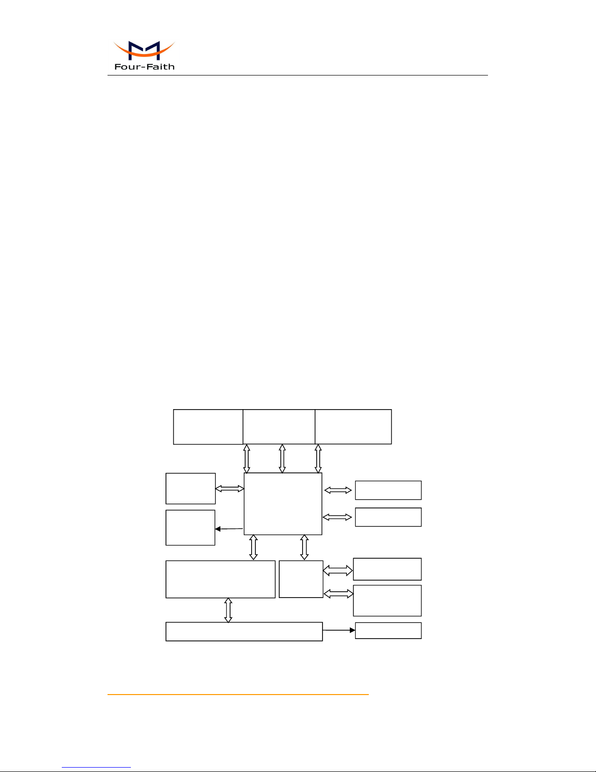
1.3 Working Principle
The principle chart of the RTU is as following:
Cellular
Module
MCU
Antenna
SIM/UIM
Interface
Indicator
Lights
SRAM&
FLASH
WDT Module
RTC Module
User Interface
RS232/RS485/RS422
Module
Power Module
8ch digital
input
8 ch analog
input
4ch relay out
4ch isolated out
User Manual
Xiamen Four-Faith Communication Technology Co.,Ltd. Page 12 of 98
Add: J1-J3,3rdFloor,No.44,GuanRiRoad,SoftWare Park,XiaMen .361008.China
http://www.fourfaith.com Tel: +86 592-6300326 6300325 6300324 Fax:+86 592-5912735
1.4 Specifications
Cellular Specification
Standard and Band
Bandwidth
TX power
RX
sensitivity
F2164 GPRS RTU
EGSM900/GSM1800MHz,
GSM850/900/1800/1900MHz(optional)
Compliant to GSM phase 2/2+
GPRS class 10, class 12(optional)
85.6Kbps
GSM850/900:
<33dBm
GSM1800/1900:
<30dBm
<-107
dBm
F2264 CDMA RTU
CDMA2000 1xRTT 800MHz
800/1900MHz(optional)
450MHz(optional)
153.6Kbps
<30dBm
<-104
dBm
Hardware System
Item
Content
CPU
Industrial 32 bits CPU
FLASH
2MB(Extendable 8MB)
SRAM
512KB(
Extendable
1MB)
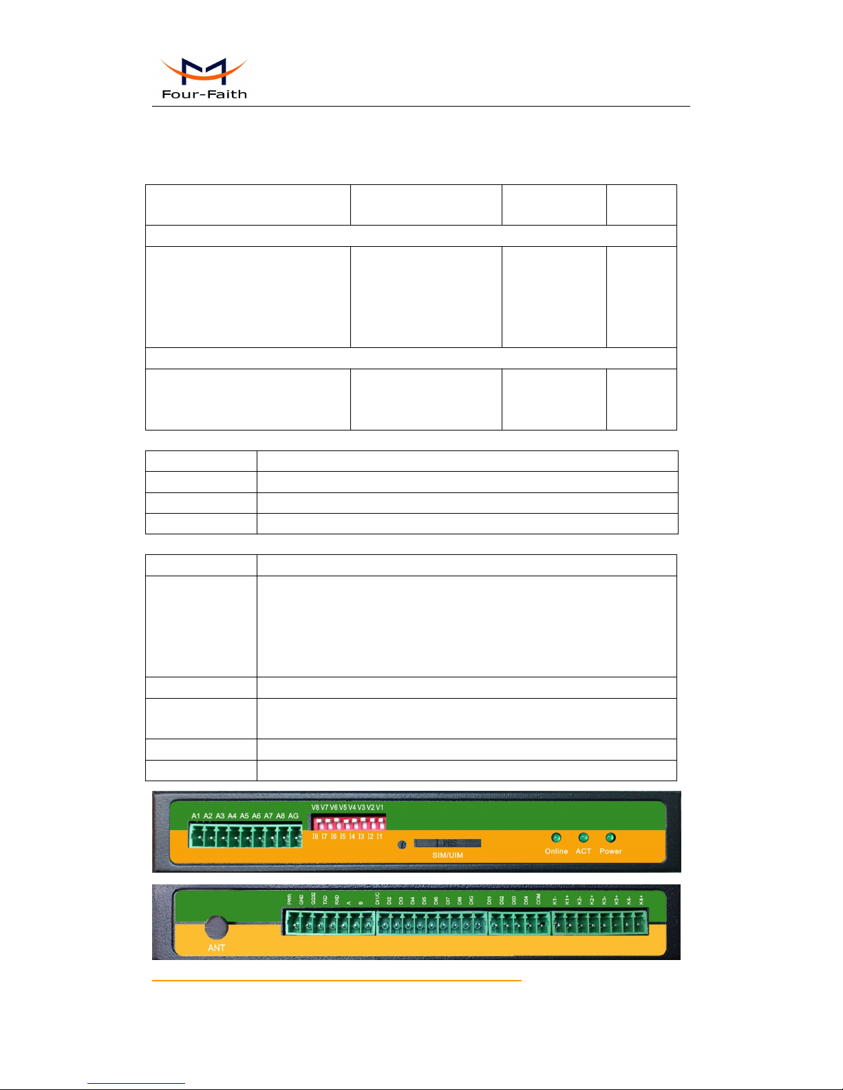
Interface Type
Item
Content
Serial
1 RS232 port and 1 RS485port, 15KV ESD protection
Data bits: 5, 6 ,7, 8
Stop bits: 1, 1.5, 2
Parity: none, even, odd, space, mark
Baud rate: 110~230400 bps
Indicator
"Power", "ACT", "Online"
Antenna
Cellular: Standard SMA female interface, 50 ohm
lighting protection(optional)
SIM/UIM
Standard 3V/1.8V user card interface, 15KV ESD protection
Power
Terminal block interface, reverse-voltage and overvoltage protection

User Manual
Xiamen Four-Faith Communication Technology Co.,Ltd. Page 13 of 98
Add: J1-J3,3rdFloor,No.44,GuanRiRoad,SoftWare Park,XiaMen .361008.China
http://www.fourfaith.com Tel: +86 592-6300326 6300325 6300324 Fax:+86 592-5912735
Power Input
Item
Content
Standard Power
DC 12V/0.5A
Power Range
DC 5~35V
Power Consumption
Working States
Power Consumption
Communication
88-100mA@12VDC
Standby
52mA@12VDC
Timing Power
Off
0.9mA@12VDC
Physical Characteristics
Item
Content
Housing
Iron, providing IP30 protection
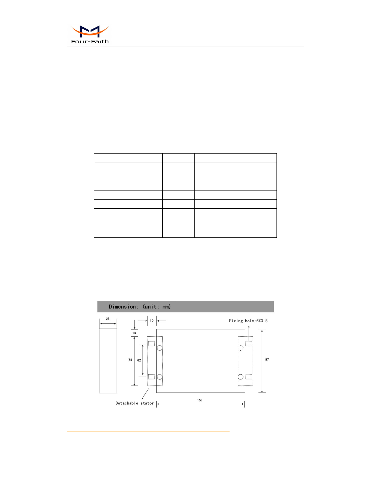
Dimensions
157x97x25 mm
Weight
500g
Environmental Limits
Item
Content
Operating
Temperature
-35~+75ºC(-31~+167℉)
Storage
Temperature
-40~+85ºC(-40~+185℉)
Operating
Humidity
95% ( Non-condensing)
User Manual
Xiamen Four-Faith Communication Technology Co.,Ltd. Page 14 of 98
Add: J1-J3,3rdFloor,No.44,GuanRiRoad,SoftWare Park,XiaMen .361008.China
http://www.fourfaith.com Tel: +86 592-6300326 6300325 6300324 Fax:+86 592-5912735
Chapter 2 Installation Introduction
2.1 General
The RTU must be installed correctly to make it work properly.
Warning: Forbid to install the RTU when powered!
2.2 Encasement List
Name
Quantity
Remark
RTU host
1
Cellular Antenna
1
Power adapter
1
RS232 data cable
1
optional
RS485 data cable
1
optional
Manual CD
1
Certification card
1
Maintenance card
1
Table 2-1 Encasement List
2.3 Installation and Cable Connection
Dimension: (unit: mm)
Figure 2-1 Installation Chart

User Manual
Xiamen Four-Faith Communication Technology Co.,Ltd. Page 15 of 98
Add: J1-J3,3rdFloor,No.44,GuanRiRoad,SoftWare Park,XiaMen .361008.China
http://www.fourfaith.com Tel: +86 592-6300326 6300325 6300324 Fax:+86 592-5912735
Installation of SIM/UIM card:
Firstly power off the RTU, and press the out button of the SIM/UIM card outlet with a needle
object. Then the SIM/UIM card sheath will flick out at once. Put SIM/UIM card into the card
sheath (Pay attention to put the side which has metal point outside), and insert card sheath back to
the SIM/UIM card outlet.
Warning: Forbid to install SIM/UIM card when powered!
Installation of antenna:
Screw the SMA male pin of the antenna to the female SMA outlet of the RTU tightly.
Warning: The antenna must be screwed tightly, or the signal quality of antenna will be influenced!
User Interface Signal Definition
Pin
Number
Function
Interface
Default function
Function expansion
1
Power
PWR
Power input positive
None
2
GND
Power input negative
None
3
RS232
G/232
RS232 GND
None
4
RXD
RS232 Data receiving
None
5
TXD
RS232 Date sending
None
6
RS485
A
RS485 positive
Reserve compatible
RS232 DTR
7
B
RS485 negative
Reserve compatible
RS232 DSR
8
Digital
Input
DI1/C
Digital input1
Counting function
9
DI2
Digital input 2
None
10
DI3
Digital input 3
None
11
DI4
Digital input 4
None
12
DI5
Digital input 5
None
13
Digital
Input
DI6
Digital input 6
None
14
DI7
Digital input 7
None
15
DI8
Digital input 8
None
16
DIG
Digital input GND
None
18
Optocoupl
er output
DO1
Optocoupler output 1
None
19
DO2
Optocoupler output 2
None
20
DO3
Optocoupler output 3
None
21
DO4
Optocoupler output 4
None
22
COM
COM GND
None
23
Relay
output
K1-
Relay output 1-
None
24
K1+
Relay output 1+
None

User Manual
Xiamen Four-Faith Communication Technology Co.,Ltd. Page 16 of 98
Add: J1-J3,3rdFloor,No.44,GuanRiRoad,SoftWare Park,XiaMen .361008.China
http://www.fourfaith.com Tel: +86 592-6300326 6300325 6300324 Fax:+86 592-5912735
25
K2-
Relay output 2-
None
26
K2+
Relay output 2+
None
27
K3-
Relay output 3-
None
28
K3+
Relay output 3+
None
29
K4-
Relay output 4-
None
30
K4+
Relay output 4+
None
31
ADC
A1
ADC 1
None
32
A2
ADC 2
None
33
A3
ADC 3
None
34
A4
ADC 4
None
35
A5
ADC 5
None
36
A6
ADC 6
None
37
A7
ADC 7
None
38
A8
ADC 8
None
39
AG
AGND
None
40
SW
V1
A1’s Sample type was Volt
I1
A1’s Sample type was Current
41
V2
A2’s Sample type was Volt
I2
A2 ’s Sample type was Current
42
V3
A3’s Sample type was Volt
I3
A3 ’s Sample type was Current
43
V4
A4’s Sample type was Volt
I4
A4 ’s Sample type was Current
44
V5
A5’s Sample type was Volt
I5
A5 ’s Sample type was Current
45
V6
A6’s Sample type was Volt
I6
A6 ’s Sample type was Current
46
V7
A7’s Sample type was Volt
I7
A7 ’s Sample type was Current
47
V8
A8’s Sample type was Volt
I8
A8 ’s Sample type was Current
Installation of cable:
F2X64 adopts industrial terminal block interface. The recommendatory cable is 28-16AWG.
The detail description of standard layout adapter and communication cables as is following:
Adapter(Rating Output 12VDC/0.5A):
Cable Color
Power Output Polarity
Black &White Alternate
Anode
Black
Cathode
RS232 Cable:
Cable Color
Corresponding DB9-M Pin Number
Brown
Pin 2
Blue
Pin 3
Black
Pin 5
User Manual
Xiamen Four-Faith Communication Technology Co.,Ltd. Page 17 of 98
Add: J1-J3,3rdFloor,No.44,GuanRiRoad,SoftWare Park,XiaMen .361008.China
http://www.fourfaith.com Tel: +86 592-6300326 6300325 6300324 Fax:+86 592-5912735
RS485 Cable:
Cable Color
Signal definition
Red
RS485(A)
Black
RS485(B)
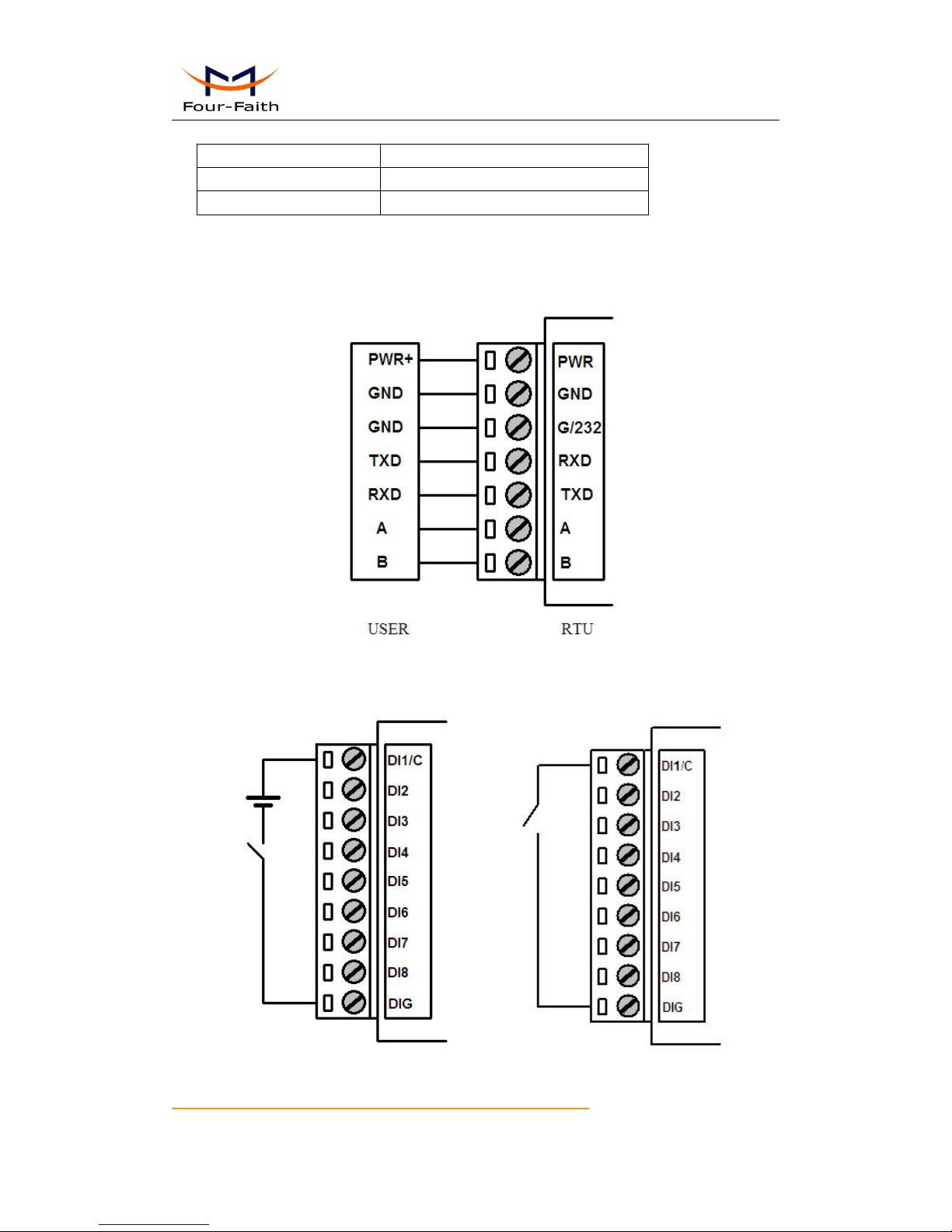
Power adapter and communication cable connection chart as following:
Digital Input cable connection
Wet contact Dry contact
User Manual
Xiamen Four-Faith Communication Technology Co.,Ltd. Page 18 of 98
Add: J1-J3,3rdFloor,No.44,GuanRiRoad,SoftWare Park,XiaMen .361008.China
http://www.fourfaith.com Tel: +86 592-6300326 6300325 6300324 Fax:+86 592-5912735
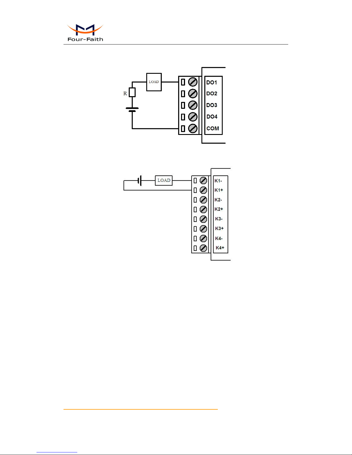
Optocoupler output cable connection
Relay output cable connection
User Manual
Xiamen Four-Faith Communication Technology Co.,Ltd. Page 19 of 98
Add: J1-J3,3rdFloor,No.44,GuanRiRoad,SoftWare Park,XiaMen .361008.China
http://www.fourfaith.com Tel: +86 592-6300326 6300325 6300324 Fax:+86 592-5912735
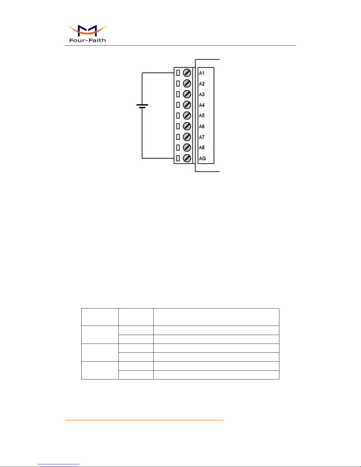
ADC cable connection
2.4 Power
The power range of the RTU is DC 5~35V
Warning: When we use other power, we should make sure that the power can supply power
above 4W.
We recommend user to use the standard DC 12V/0.5A power adaptor.
2.5 Indicator Lights Introduction
The RTU provides three indicator lights: “Power”, “ACT”, “Online”.
Indicator
Light
State
Introduction
Power
ON
RTU is powered on
OFF
RTU is powered off
ACT
BLINK
Data is communicating
OFF
No data
Online
ON
RTU has logged on network
OFF
RTU hasn’t logged on network

User Manual
Xiamen Four-Faith Communication Technology Co.,Ltd. Page 20 of 98
Add: J1-J3,3rdFloor,No.44,GuanRiRoad,SoftWare Park,XiaMen .361008.China
http://www.fourfaith.com Tel: +86 592-6300326 6300325 6300324 Fax:+86 592-5912735
Chapter 3 RTU Function Introduction
RTU is based on our ip modem which has realized data transparent transmission. It can collect
analog signal and digital signal. It also can output digital signal including 4 optocoupler isolated
outputs and 4 relay outputs. It has pulse counter. Main funcions as following:
1. Support dual data centers, one main and another backup, support multiple data centers
and it can support maximum 5 data centers, support multi-center multi-function(for
example: one data center works with MODBUS RTU protocol , another data center can
work with RTU extended protocol)
2. support multi online trigger ways, including SMS, ring and data. Support link
disconnection when timeout
3. Network is automatically connect,when device offline, it will automatically reconnect.
4. Support RS232/RS485 MODBUS RTU protocol, support TCP MODBUS RTU protocol
using TCP2COM software that converts TCP to virtual serial port.
5. Alarm function: Alarm information are reported through RTU extended protocol , SMS,
or both SMS and RTU extended protocol
6. Multiple configure methods.
7. Local and remote upgrade firmware.
8. Scheduled turn on and turn off power function make the device work in low-power mode
3.1 Multiple servers funticon
RTU support multi-center multi-function. Each center functions can be configured independently,
parameter settings please refer to appendix 4.1.4.6 Data Service Center Settings. Connection
protocol please refer to appendix 4.1.4.7 Work Mode.
3.2 MODBUS protocol
RTU support RS232/RS485 MODBUS RTU protocol. The principle of TCP MODBUS RTU
protocol is the same as RS232/RS485 MODBUS RTU protocol. TCP2COM softwave we
provided realize TCP to virtual serial port function(it can remotely transfer MODBUS RTU
protocol). The following introduces MODBUS RTU protocol, All of the following MODBUS data
are high byte first (big-endian mode).
3.2.1 MODBUS settings
Enable MODBUS function, related settings please refer to appendix 4.1.4.5 ModBus Setting, it
also need to configure the digital input, digital output, analog input and counter input

User Manual
Xiamen Four-Faith Communication Technology Co.,Ltd. Page 21 of 98
Add: J1-J3,3rdFloor,No.44,GuanRiRoad,SoftWare Park,XiaMen .361008.China
http://www.fourfaith.com Tel: +86 592-6300326 6300325 6300324 Fax:+86 592-5912735
independently.
3.2.2 TCP2COM description
TCP2COM softwave realize TCP to virtual serial port function. The principle of TCP MODBUS
RTU protocol is the same as RS232/RS485 MODBUS RTU protocol. About using TCP2COM
softwave, please refer to appendix 5.1 TCP2COM Manual.
3.2.3 MODBUS digital IO input introduction
The MODBUS function code of digital IO input is 0x02(read input status), the starting register
address is 0, there are total 8 digital input(register address from 0 to 7). The MODBUS settings of
digital IO input please refer to appendix 4.1.4.1 Digital input function.
Eg:
Query all digital input ports (all 8 input ports), command as following:
01 02 00 00 00 08 79 CC
Parse command:
Byte-
orders
1234567
8
Content
01020000000879
CC
Parsing
Slave
Address
Function
code
Start address
number of registers
Checksum
Meanin
g
01
Read
input
status
Address is 0-7
corresponding to
IO1-IO8
seperately。
Read the value of
digital IO input.
This example read
8 ports . If read one
channel, this
parameter should
be 0001
checksum
Response
01 02 01 00 A1 88
Parse response:
Byte-
orders
12345
6
Content
01020100A1
88
Parsing
Slave
Address
Function
code
Data length
IO status value
Checksum
Meaning
01
Read input
Data length
IO status value,
checksum

User Manual
Xiamen Four-Faith Communication Technology Co.,Ltd. Page 22 of 98
Add: J1-J3,3rdFloor,No.44,GuanRiRoad,SoftWare Park,XiaMen .361008.China
http://www.fourfaith.com Tel: +86 592-6300326 6300325 6300324 Fax:+86 592-5912735
statuss
bit0~bit7
corresponding to
IO1-IO8
3.2.4 MODBUS digital IO output introduction
The MODBUS function code of digital IO output is 0x05, the starting address is 0, there are total
8 output ports(address 0-3 used for optocouplers output ports, corresponding to optocouplers port
1-4, address 4-7 used for relay outputs,corresponding to rlay output 1-4). The MODBUS
configuration of digital IO output please refer to appendix 4.1.4.2 Optocoupler and relay settings.
Eg:
Control one digital IO output, command as following:
01 05 00 00 FF 00 8C 3A
Parse command:
Byte-
orders
1234567
8
Content
01050000FF008C
3A
Parsing
Slave
Address
Functio
n code
Start address
Output value:FF00
means logic 1 ,
0000
means logic 0.
checksum
Meanin
g
01
Force
single
coil
Address is 0-3 used
for optocouplers
output, address 4-7
used for relay
outputs
The digital output
value.
checksum
Response
01 05 00 00 FF 00 8C 3A
Parse response:
The response command is the same as sending command, please refer to appendix the above
control command.
3.2.5 MODBUS read digital IO output introduction
The MODBUS function code of readding digital IO output is 0x01, the starting address is 0, there
are total 8 output ports(address 0-3 used for optocouplers output ports, corresponding to
optocouplers port 1-4, address 4-7 used for relay outputs,corresponding to rlay output 1-4). The
MODBUS configuration of readding digital IO output please refer to appendix 4.1.4.2
Optocoupler and relay settings.
Eg:

User Manual
Xiamen Four-Faith Communication Technology Co.,Ltd. Page 23 of 98
Add: J1-J3,3rdFloor,No.44,GuanRiRoad,SoftWare Park,XiaMen .361008.China
http://www.fourfaith.com Tel: +86 592-6300326 6300325 6300324 Fax:+86 592-5912735
Read all digital IO output, command as following:
01 01 00 00 00 08 3D CC
Parse command:
Byte-
orders
1234567
8
Content
0101000000083D
CC
Parsing
Slave
Address
Functio
n code
Start address
Coil number
checksum
Meanin
g
01
Force
single
coil
Address is 0-3 used
for optocouplers
output, address 4-7
used for relay
outputs
The digital output
value.
checksum
Response:
01 01 01 55 91 B7
Parse response:
Byte-
orders
12345
6
Content
0101015591
B7
Parsing
Slave
Address
Function
code
Data length
IO status
value
checksum
Meaning
01
Read coil
Bytes count
IO status
value,
bit0~bit7
correspondi
ng to
IO1-IO8
checksum
3.2.6 MODBUS counter introduction
The counter input port and the first channel of digital IO input is the same pin.
The MODBUS function code of reading counter value is 0x03(read holding register), the starting
address is 0. The MODBUS function code of setting counter initial value is 0x10(preset multiple
registers), the starting address is 0. The MODBUS parameters of counter please refer to appendix
4.1.4.4 RTU counter settings.
Eg:
Read counter value, command as following:
01 03 00 00 00 02 C4 0B
Parse command:

User Manual
Xiamen Four-Faith Communication Technology Co.,Ltd. Page 24 of 98
Add: J1-J3,3rdFloor,No.44,GuanRiRoad,SoftWare Park,XiaMen .361008.China
http://www.fourfaith.com Tel: +86 592-6300326 6300325 6300324 Fax:+86 592-5912735
Byte-
orders
1234567
8
Content
010300000002C4
0B
Parsing
Slave
address
Functio
n code
Start address
number of
Registers
checksum
Meanin
g
01
Read
holding
register
Address 0
corresponding to
counter
Counter value is a
32 bit value,so,
need to read two 16
bit regiesters
checksum
Response
01 03 04 00 00 00 00 FA 33
Parse response:
Byte-
orders
123456789
Conten
t
01030400000000FA33
Parsing
Slave
address
Functi
on
code
Data
length
Data 1
Data 2
Checksum
Meani
ng
01
Read
holdin
g
register
Data
length
Counter value is
32 bits
Corresponding to
high 16 bits
Counter value is
32 bits
Corresponding to
low 16 bits
Checksum
Set counter initial value, command as following:
01 10 00 00 00 02 04 00 00 00 0A 73 A8
Parse command:
Byte-
orders
123456789
Conten
t
011000000002040000
Parsing
Slave
address
Functi
on
code
Start address
Number of
Registers
c
High 16 bits
value
Meani
ng
01
Preset
multipl
e
register
s
Address 0
corresponding to
counter
Counter value is
32 bits, so need
to write two 16
bits registers
Byte
count
Correspond to
high 16 bits of
counter value

User Manual
Xiamen Four-Faith Communication Technology Co.,Ltd. Page 25 of 98
Add: J1-J3,3rdFloor,No.44,GuanRiRoad,SoftWare Park,XiaMen .361008.China
http://www.fourfaith.com Tel: +86 592-6300326 6300325 6300324 Fax:+86 592-5912735
Contiune
101112
13
000A73
A8
Low 16 bits value
Checksum
Correspond to low 16 bits of counter value
checksum
Response
01 10 00 00 00 02 41 C8
Parse response:
Byte-
orders
1234567
8
Content
01100000000241
C8
Parsing
Slave
Address
Functio
n code
Start address
number of registers
Checksum
Meanin
g
01
Preset
multiple
registers
Address 0
corresponding to
counter
Counter value is 32
bits, so need to
operate two 16 bits
registers
checksum
3.2.7 MODBUS analog input introduction
The MODBUS function code of analog input is 0x04(read input register), the starting address is 0,
there are total 8 channels (the value of each channel is a signed 32-bit data, this data is the actual
value of the sensor). The MODBUS parameters of analog input please refer to appendix 4.1.4.3
Analog input function.
Query all channels(all 8 channels) of analog input, command as following:
01 04 00 00 00 10 F1 C6
Parse command:
Byte-
orders
1234567
8
Content
010400000010F1
C6
Parsing
Slave
Address
Functio
n code
Start Address
number of registers
Checksum
Meanin
g
01
Read
input
register
Address 0000-0010
correspond to
AIN1-AIN8
Analog input value
is 32 bits, high 16
bits first. If read
one channel, this
parameter should
be 0002
checksum

User Manual
Xiamen Four-Faith Communication Technology Co.,Ltd. Page 26 of 98
Add: J1-J3,3rdFloor,No.44,GuanRiRoad,SoftWare Park,XiaMen .361008.China
http://www.fourfaith.com Tel: +86 592-6300326 6300325 6300324 Fax:+86 592-5912735
Response
01 04 20 00 00 01 82 00 00 00 0C 00 00 00 0C 00 00 00 0C 00 00 00 0C 00 00 00 0C 00 00 00 0C
00 00 00 0C B0 A2
Parse response:
Byte-
orders
1234567
Content
01042000000182
Parsing
Slave
address
Function
code
Data
length
Data 1
Data 2
Meaning
01
Read
input
register
Byte
count
Corresponding to high
16 bits of first channel
value. Te value of each
channel is a signed
32-bit data
Corresponding to low
16 bits of first channel
value. Te value of each
channel is a signed
32-bit data
continue
891011…323334353637
0000000C…0000000CB0A2
Data 3
Data 4
…
Data 15
Data 16
Checksum
Corresponding
to high 16 bits
of second
channel value.
Te value of
each channel is
a signed 32-bit
data
Corresponding
to low 16 bits
of second
channel value.
Te value of
each channel is
a signed 32-bit
data
…
corresponding
to high 16 bits
of eighth
channel value.
Te value of
each channel is
a signed 32-bit
data
corresponding
to low 16 bits
of eighth
channel value.
Te value of
each channel is
a signed 32-bit
data
checksum
3.3 RTU extended protocol
RTU extended protocol has the following main functions:
1. Acquisition data(including analog input and digital input) are reported periodically.
2. Reporting mode can be selected. there are three reporting modes, including Network only,
SMS only and Main network ,SMS as backup(it uses SMS. when network connection fail)
3. When reporting acquisition data failure, acquisition data are saved to 2M byte SPI
nonvolatile flash which is saved forever even if the device powered off.
4. The data center can query acquisition data actively
5. It has counter function that the initial value of the counter can be configured, its realtime
value can be queried

User Manual
Xiamen Four-Faith Communication Technology Co.,Ltd. Page 27 of 98
Add: J1-J3,3rdFloor,No.44,GuanRiRoad,SoftWare Park,XiaMen .361008.China
http://www.fourfaith.com Tel: +86 592-6300326 6300325 6300324 Fax:+86 592-5912735
6. It provede the transparent transmission tunnel between the data center and the terminal
devices which connected to the RTU RS232/485 port. This function works same as our
company’s ip modem.
7. It has alarm function and the alarm information can be reported periodically(alarm trigger
conditions can be configured independently).
8. It can be controlled to reboot from the remote side.
9. support remote configure the parameters
10. Local and remote upgrade the firmware.
Please refer to appendix 5.2 RTU center service.
3.4 Alarm function
Alarm informations can be reported through RTU extended protocol only, SMS only and both
SMS and RTU extended protocol. When alarm informations are reported through SMS, alarm
phone number and alarm content of each channel can be configured independently. detail
description please refer to appendix 5.2.7 Alarm information.
3.5 Multiply configure parameters
All the RTU parameters can be configured through RS232/RS485 、 SMS and RTU extended
protocol. Please refer to appendix chapter 4 configuration.
3.6 Remote upgrade firmware
RTU can remote upgrade firmware through TCP or UDP. First put new firmware (the version
should higher than the current software version) on RTU center software(its manual refer to 5.2
RTU center service) installation directory. then, configure upgraded parameters, these parameters
can be configured by SMS or RTU extended protocol. When RTU received the valid upgrade
parameters, it will upgrade the firmware automatically. Detail settings please refer to appendix
4.2.2.2 Overall setting by SMS or 5.10 Remote configure.
User Manual
Xiamen Four-Faith Communication Technology Co.,Ltd. Page 28 of 98
Add: J1-J3,3rdFloor,No.44,GuanRiRoad,SoftWare Park,XiaMen .361008.China
http://www.fourfaith.com Tel: +86 592-6300326 6300325 6300324 Fax:+86 592-5912735
Chapter 4 Configuration
All the RTU settings can be configured through RS232/RS485、SMS and RTU extended protocol.
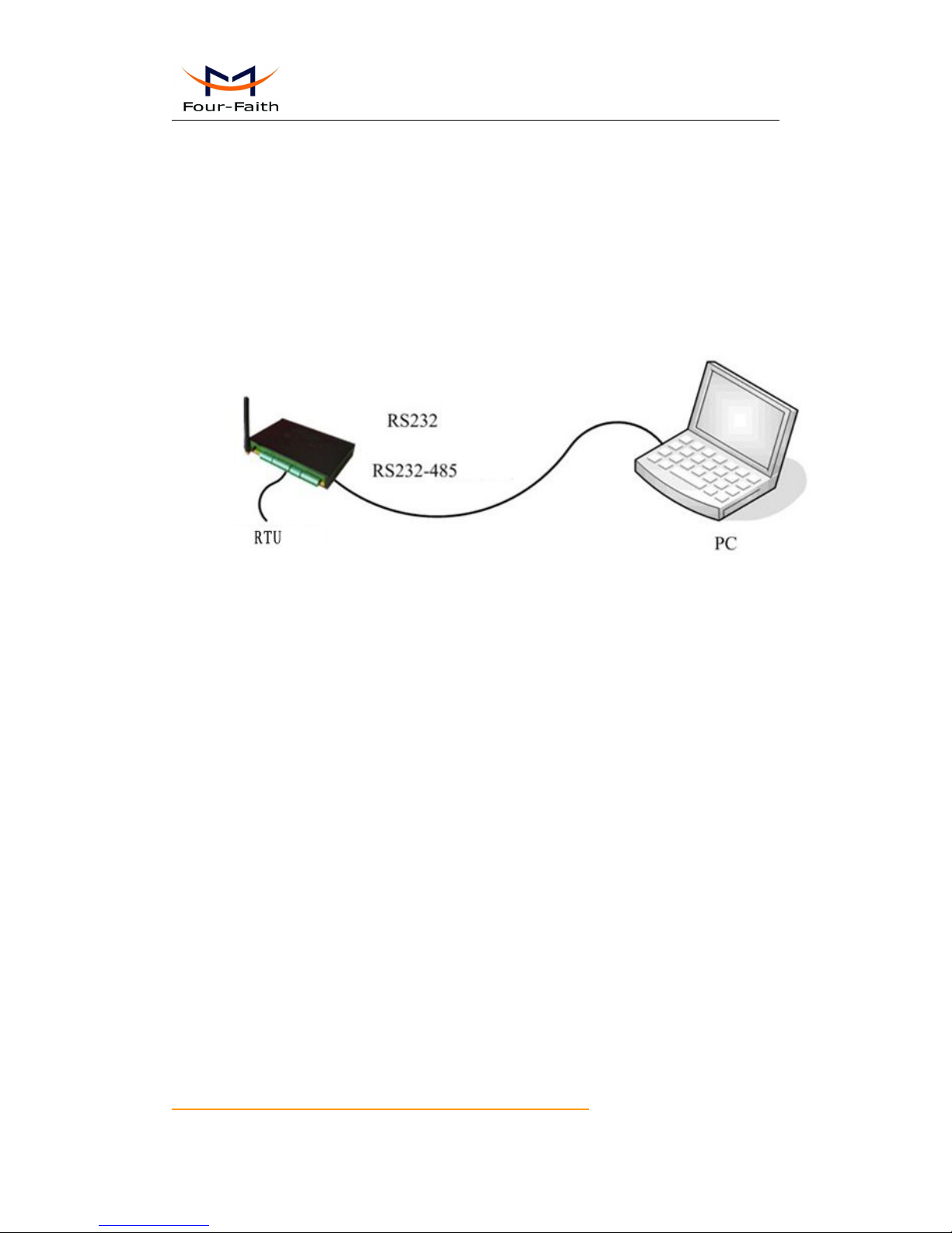
4.1 RS232/RS485 Configuration
Before configuration, It’s necessary to connect the RTU with the configure PC by the shipped
RS232 or RS232-485 cable as following.
4.1.1 Configuration introduction
There are two ways to configure the RTU:
Configuration software tool: All the settings are configured through the shipped software tool. It’s
necessary to have one PC to run this tool.
Extended AT command: All the settings are configured through AT command, so any device with
serial port can configure it. Before configuration with extended AT command, you should make
RTU enter configure state. The steps how to make RTU enter configure state, please refer to
appendix appendix.
The following describes how to configure RTU with the configure software tool. At the same time,
it gives out the corresponding AT command of each configuration item.
User Manual
Xiamen Four-Faith Communication Technology Co.,Ltd. Page 29 of 98
Add: J1-J3,3rdFloor,No.44,GuanRiRoad,SoftWare Park,XiaMen .361008.China
http://www.fourfaith.com Tel: +86 592-6300326 6300325 6300324 Fax:+86 592-5912735
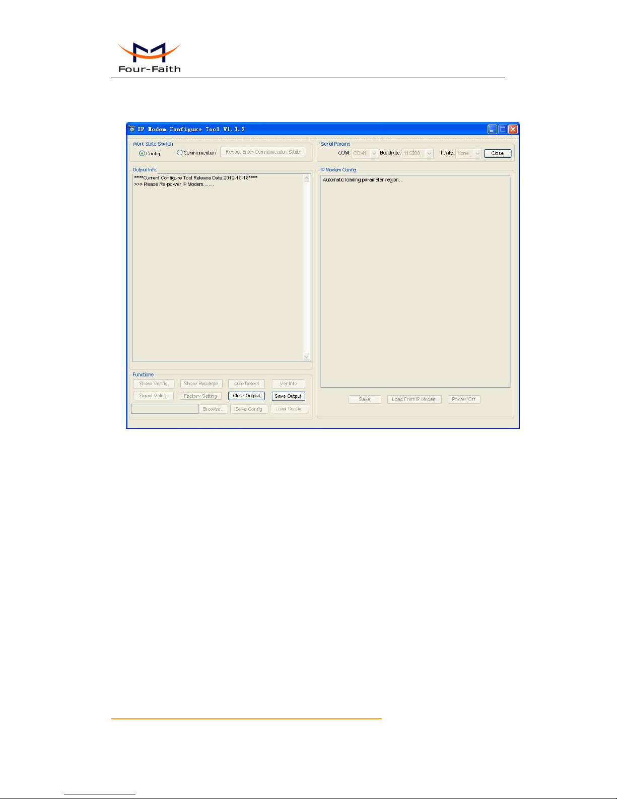
4.1.2 Run the configure tool
The “Serial Parameters” column shows the current serial port settings. To configure RTU,
please choose the correct serial port which connects to RTU, and the baud-rate is 115200 with no
parity, then open the serial port. If the button text is“Close”, it shows the serial port now has been
opened. If the text is “Open”, you should open the port first. When the port opened, the “Output
Info” column will display
“Port(COM1) Has Opened,Please Re-Power the RTU,
Waiting RTU Enter Configure State...”
User Manual
Xiamen Four-Faith Communication Technology Co.,Ltd. Page 30 of 98
Add: J1-J3,3rdFloor,No.44,GuanRiRoad,SoftWare Park,XiaMen .361008.China
http://www.fourfaith.com Tel: +86 592-6300326 6300325 6300324 Fax:+86 592-5912735
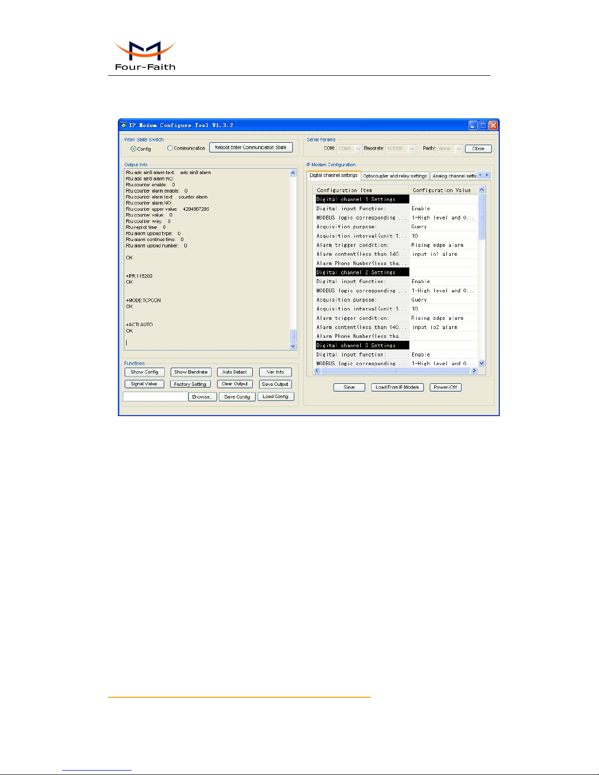
4.1.3 Re-power RTU
After Re-power RTU, The configure tool will make it enter configure state. At the same time, the
software will load current settings from RTU and displays on the right configure columns. It’s
now ready to configure.
 Loading...