

Fountek Altitude 3500 Brochure
FOUNTEK
ALTITUDE 3500
Integrated Amplifier
A3500 ( Version -V1) 240V AC 24-10-05
OWNERS MANUAL

CONTENTS
3. INTRODUCTION
4. IMPORTANT NOTES ( WARNING !)
5. POWER INPUT CONNECTION
6. CONNECTING SPEAKERS
7. SERVICING THE AMPLIFIER
8. LOCATION AND VENTILATION
9. TOP VIEW VALVE LOCATION
10. REAR VIEW DIAGRAM
11. FRONT VIEW DIAGRAM
12. OPERATIONAL NOTES
13. SPECIFICATIONS
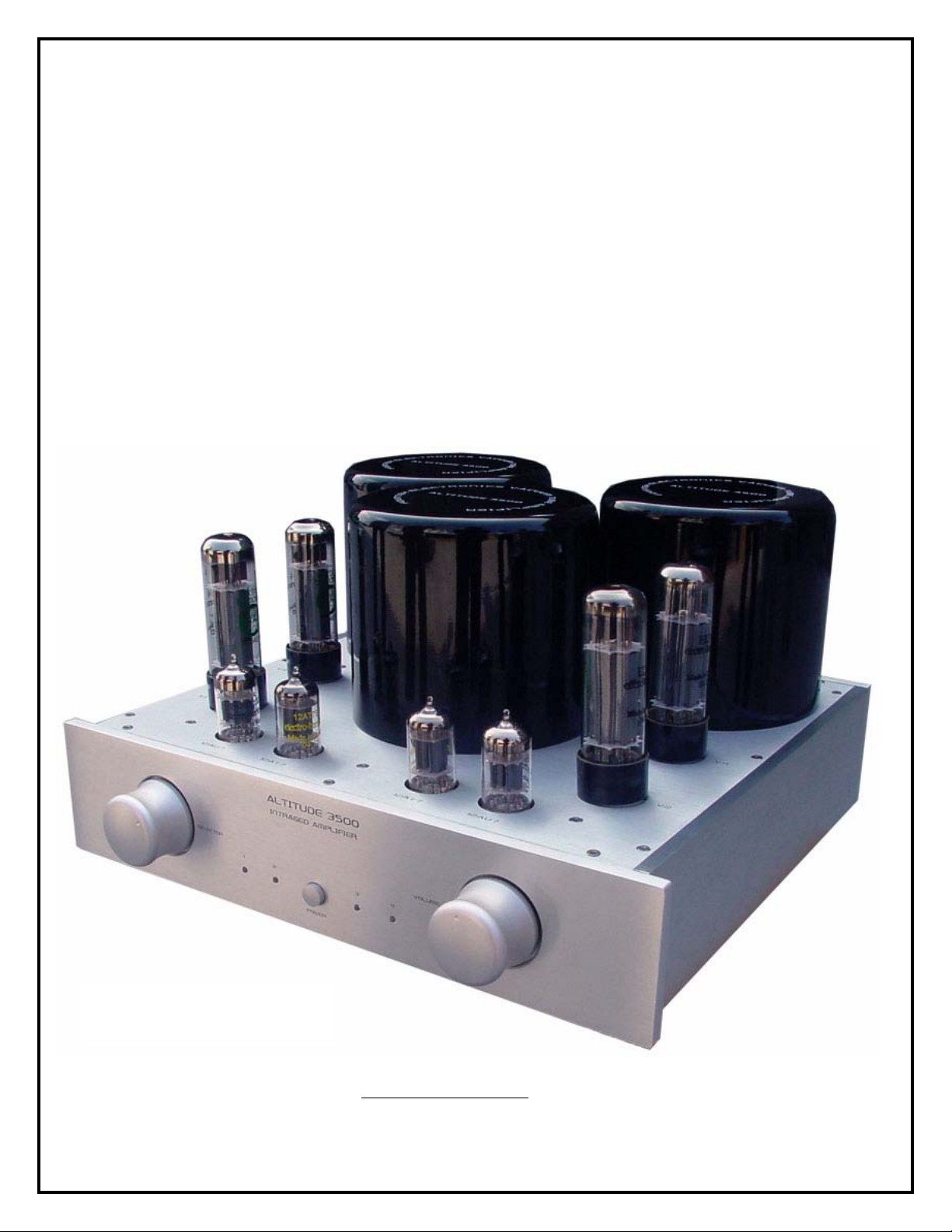
14. ALTITUDE 3500 PICTURE
2

INTRODUCTION
Thank you for purchasing the Fountek Electronics Altitude 3500 Integrated valve
amplifier. The circuit design lay out and component quality used has been chosen
carefully after years of development and refinement for reliability to ensure the highest
quality of musical reproduction with accurate and emotional delivery of the sound
stage .
The Altitude 3500 Integrated valve amplifier features only the best available
components with the shortest and cleanest signal paths possible with direct coupling
used on the input stages to improve signal transit response .
High quality electrolytic and non electrolytic capacitors have been used throughout
the Altitude 3500 amplifier in critical signal areas to ensure instant energy for fast
dynamic midrange and top end transients with tight very dynamic bass performance
normally not found on valve amplifiers.

IMPORTANT NOTES ( WARNING !)
CHILDREN & PETS
If you have small children or pets, you should consider placing the amplifiers out of reach
to prevent damage to the amplifier or damage to your small children or pets by the
amplifier as the valves do get hot during operation.
WATER & MOISTURE
As with any electrical equipment, these amplifiers should not be used near water or
moisture.
Keep clear of open windows
CLEANING THE AMPLIFIER
Turn off the power on the front panel of the amplifier and remove the power cable from the
mains wall socket completely before cleaning the panels.
## Use a soft cotton cloth or cotton gloves only
## Do not use any water, alcohol, chemicals, or cleaning sprays on any part of the
amplifier chassis or valves
Valves may become loose during transit straighten and press down each tube firmly
before into its appropriate valve socket before plugging the amplifier into the AC mains
socket.
HEAT FROM THE AMPLIFIER
Do not touch the valves after the amplifier has been switched on, as the valves become
very hot during operation and should only be handled after the power has been turned off
and the valves have cooled. Allow at least 15 to 20Minuites for the amplifier to cool down
Your amplifier has been factory set to the correct mains voltage for your country.
The voltage setting is marked on the serial badge, located on the rear panel neat the IEC
mains input socket.
Check that this complies with your local main supply.
SHOCK HAZZARD #####
High voltages are contained inside the amplifier
DO Not remove the metal base cover of the amplifier.
DO Not Operate the amplifier with the valves removed from the valve sockets
4
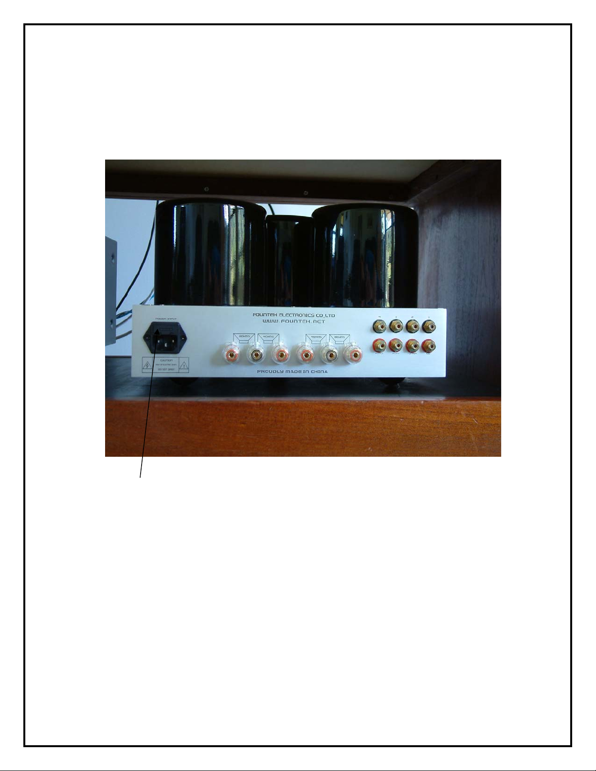
POWER INPUT CONNECTION
POWER INPUT _ IEC 240V SOCKET/FUSE HOLDER
Your amplifier has been factory set to the correct mains voltage for your country.
The voltage setting is marked on the serial badge, located on the rear panel.
Check that this complies with your local supply.
Please use the IEC power cord supplied with the unit and ensure it is firmly pushed
into the IEC 240V AC socket at the rear of the amplifier and the amplifier installation
and connections have been double-checked before connecting the amplifier to the
240V AC power outlet before switching on the power
REPLACING FUSE
First be sure the unit is turned off and remove the 240V IEC mains cable before
replacing the fuse
The fuse is mounted in the top IEC 240V AC socket at the rear of the amplifier
under a plastic panel.
Replace the fuse only with the recommended type (# see Specifications for type)
 Loading...