

Fountainhead OML-1, GGS-1, RML-1, SML-1, SML-2 Owner's Manual
The Fountainhead Group
Compressed Air Sprayer
1-800-311-9903
Owner’s Manual
Models OML-1, RML-1, GGS-1, SML-1, SML-2
WARNING!
The sprayer is operated with liquid under pressure. Failure to observe CAUTION and to follow instructions for operating and cl eaning
can cause tank, hose and other parts to be weakened and/or rupture under pressure. This can result in SERIOUS INJURY from high
pressure discharge of liquids
or forcible ejection of parts. DO NOT USE FLAMMABLE MATERIALS IN THIS SPRAYER. Material could ignite or explode, causing seri
ous injury. FOR SAFE USE
OF THIS PRODUCT - YOU MUST READ AND FOLLOW ALL INSTRUCTIONS BEFORE USE.
TEST SPRA
YER WITH W
ATER BEFORE USING ANY CHEMICALS.
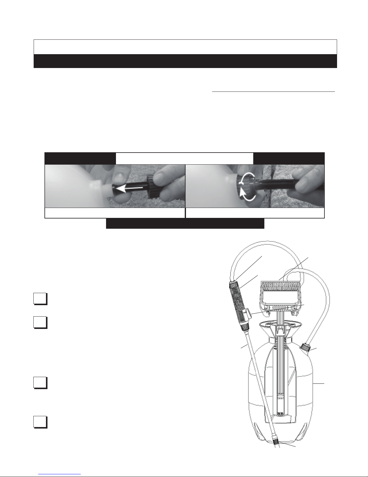
ASSEMBLY INSTRUCTIONS
1.
2.
BARB
CONNECTION
SHUT-OFF
PUMP HANDLE
SHUT-OFF
LOCK
EXTENSION
BARB
CONNECTION
TANK
NOZZLE
HOSE ASSEMBLY TO TANK:
IMPORTANT: Two
identical
hose nuts are included in the parts kit. Both
hose nuts are
required for proper assembly of the sprayer. Do not
attempt
to
heat,
or alter
hose, hose nut, or barb prior to assembly.
Slide hose nut over end of hose (observe proper hose nut
orientation in above diagram). Push hose completely onto tank
barb, as shown in step #1 of above diagram.
Slide hose nut along hose and over barb threads. Turn hose nut
clockwise to completely tighten over hose, as shown in step #2 of
above diagram (do not use tools).
HOSE ASSEMBLY TO SHUT-OFF:
Repeat steps #1 and #2 above, while connecting hose to barb of shut-off.
IMPORTANT:
1.
2.
It is recommended to test sprayer using plain tap water before
spraying chemicals. Test all connections for possible leaks. Use
proper eye protection while testing. If sprayer does not pass the
water test, call our customer service center before using sprayer
with chemicals.
Make sure hose is not cracked or frayed and does not show signs of
swelling. Make sure the hose is securely connected to sprayer.
OPERATING INSTRUCTIONS ARE CONTINUED ON NEXT PAGE
E-mail: Info@TheFGI.com • Web site: www.TheFountainheadGroup.com
SAFETY PRECAUTIONS:
1. R ead owne r’s m anu al co mp let ely befo re
operating this sprayer.
2. This sprayer is designed for light duty lawn and
garden use only.
3. A lways use goggles, glov es and pro tective
clothing when using sprayer.
4. Read and follow all instructions and cautions on
label of products used in this sprayer.
5. Spray when air is calm to prevent drift of
chemical.
6. Do not leave sprayer in the sun when not in
use.
7. Never use flammable liquids, caustics, acids
or hot water in this tank.
8. Never store chemicals in this tank.
9. Always release pressure when sprayer is not in
use and before removing pump from tank.
10. Never stand with face or body over sprayer when
pressurizing tank or releasing pressure.
11. Clean and rinse sprayer thoroughly after each use.
12. Never attempt to alter sprayer from original
condition.
13. Always use replaceme nt parts from original
manufacturer.
1-800-311-9903
If you have any problems with, or have any questions about your sprayer,
BEFORE YOU
RETURN IT TO THE STORE, CALL OUR TOLL FREE CUSTOMER SERVICE CENTER AT:
HOSE ASSEMBLY INSTRUCTIONS
IMPORTANT
1
1
1
1
1
2
2
2
2
2
IMPORTANT
1
1
1
1
1
1. PUSH HOSE COMPLETELY ON. 2. TIGHTEN NUT COMPLETELY.
! !
NEVER USE SPRAYER WITHOUT NUT.
Remove pump as described in
finish section.
Fill tank with tap water. Replace pump and turn
clockwise to tighten. Agitate tank to rinse chemical off
tank wall and pump.
Remove pump and empty contents into gravel or bare soil.
Refill tank with tap water.
Check to be sure pump is free of debris and place pump
into tank. Turn handle clockwise to tighten pump.
Pressurize tank. Follow all instructions in pressurize
section.
Point nozzle away from you and spray for
approximately 30 seconds to clean hose and shut-off.
Release pressure as outlined in operating and finish
sections.
Empty contents as in step 3.
Repeat steps 4 thru 8 until thoroughly cleaned. Note: It
is best to keep 2 sprayers: One for herbicides and one
for other products, such as fertilizers or insecticides.
CLEANING SPRAYER
SPRAYER STORAGE
SPRAYER MAINTENANCE
1.
2.
3.
4.
5.
6.
7.
8.
9.
1.
2.
3.
4.
Pump should be periodically oiled by dropping 10 to 12
drops of light oil down pump rod through opening in cover.
If nozzle clogs: remove nozzle assembly, disassemble nozzle
and clean openings of any obstructions.
Never use any tool to remove pump if there is pressure in
sprayer.
Sprayer tank should be hung upside down, with pump
removed, in a warm dry location.
Do not store or leave any solution in tank after use.
Store in a warm dry location out of direct sunlight.
KEEP SPRAYER OUT OF REACH OF CHILDREN.
1.
2.
3.
IMPORTANT! Always ensure pressure is released from
tank before filling or servicing.
To release pressure, press
button on shut-off until the unit stops spraying. Then, and
only then, it is safe to remove pump.
1.
2.
Remove pump by turning pump handle counterclockwise.
Fill tank to desired level (always refer to chemical
manufacturer for proper mixture)
Place pump into tank opening and turn handle
clockwise to tighten.
3.
PRESSURIZING:
1.
2.
Make sure shut-off lock is not engaged (if shut-off
lock is engaged while pressurizing, the unit will
immediately start spraying)
Pressurize sprayer by pumping handle in a smooth
up and down motion. When desired pressure is
achieved, lock handle onto pump.
SPRAYING:
1.
2.
Point nozzle away from you. Press shut-off button to
begin spraying. Release button to stop spraying. When
using adjustable nozzle, adjust spray pattern by turning
nozzle tip. (Note: Flat fan nozzle is not adjustable).
For continuous spraying, push lock onto shut-off button.
FINISH:
1.
2.
Direct nozzle away from you and press button on shut-off
until unit stops spraying (this will release pressure in tank).
Turn pump handle counterclockwise to remove pump.
OPERATING INSTRUCTIONS
1-800-311-9903
1-800-311-9903
If you have any problems with, or have any questions about your sprayer,
BEFORE YOU
RETURN IT TO THE STORE, CALL OUR TOLL FREE CUSTOMER SERVICE CENTER AT:
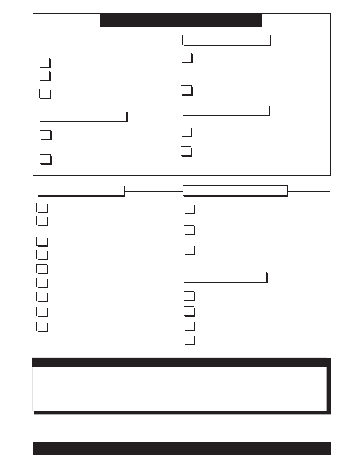
1 171015 Check
Valve
2 171653 Nozzle Cap
3 178354 Shut-off Assembly
4 180284 Fan Nozzle
5 180287 Parts / Instructions
6 180426 1 Gallon Tank-Yellow
6 180425 1 Gallon Tank-Natural
6 180477 2 Gallon Tank-Yellow
7 180299 Pump Gasket
8 180300 O-Ring, Pump
9 180305 Pump Assembly
10 180308 Hose 32”
KEY NO. PART # DESCRIPTION KEY NO. PART # DESCRIPTION
11 178363 Extension Curved
12 180332 Parts Kit
13 1783541 Hose /
Shut-off Nut
14 1785096
O-Ring, Nozzle End
15 1785097
O-Ring, Base End
KEY NO. PART # DESCRIPTION
 Loading...