

Fountainhead D.B.Smith Use And Care Manual
Manual No. 181959
Rev B. 1/8/13
ECN13-001
5 1/2” x 8 1/2” Booklet
Do Not Return This Sprayer To The Store
For Help, Information or Parts, Call : 1-800-311-9903
The Fountainhead Group, Inc.
23 Garden St., New York Mills, NY 13417
1-800-311-9903
www.TheFountainheadGroup.com
CAUTION: Read and follow all instructions
Use and Care Manual
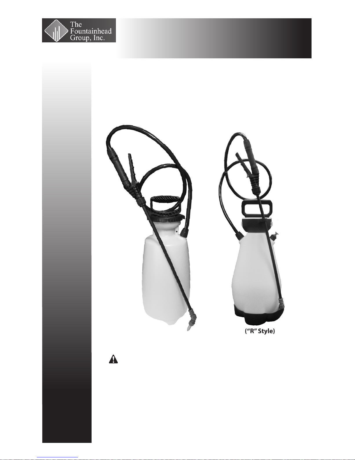
D.B. Smith
Professional Series Sprayers
(“O” Style)
(“R” Style)

Page 2
Do not return sprayer to store, if you experience problems or have questions contact
our toll free Customer Service Center, M-F 8A.M. - 5P.M., EST, at 1-800-311-9903, or
e-mail: Info@TheFGI.com, or access online at: www.TheFountainheadGroup.com.
SAFETY PRECAUTIONS
• Read owner’s manual completely before operating this sprayer.
• Always use goggles, gloves, and protective clothing when using sprayer.
• Read and follow all instructions and cautions on label of products used in this sprayer.
• Never use ammable liquids, caustics, acids, or hot water in this tank.
• Do not leave sprayer in the sun when not in use.
• Spray when air is calm to prevent drift of chemicals.
• Do not use sprayer near open ame or anything that could cause ignition of the spray.
• Always inspect hose and all hose connections before each use. A damaged hose, or loose hose
connection can result in unintended exposure to the pressurized chemical, resulting in serious injury or
property damage.
• Do not lift or carry sprayer by the hose, shut-o valve, or extension. Carry by pump handle only,
making sure handle is properly locked in place before lifting.
• Do not pressurize with any mechanical device such as an air compressor, since this can create a
dangerous pressure level and bursting of parts resulting in serious injury. Only use original pump.
• Do not store chemicals in this tank.
• Always release pressure when sprayer is not in use and before removing pump from tank.
• Do not stand with face or body over top of tank when pumping or loosening pump, to prevent pump or
solution from striking you, resulting in serious injury.
• Clean and rinse sprayer thoroughly after each use.
• Never attempt to alter sprayer from original condition.
• Always use replacement parts from original manufacturer.
• Keep the sprayer and all chemicals out of the reach of children.
WARNING
The sprayer is operated with liquid under pressure. Failure to observe caution and to follow instructions
for operating and cleaning can cause tank, hose and other parts to be weakened and rupture under
pressure. This can result in serious injury from high pressure discharge of liquids or forcible ejection of
parts. Do not use ammable materials in this sprayer. Material could ignite or explode, causing serious
injury and/or possible death. For safe use of this product, you must read and follow all instructions before
use.
TEST SPRAYER WITH WATER BEFORE USING ANY CHEMICALS.
CAUTION
Always empty, clean and dry tank, pump system, shut-o, hose, and extension after each use. FAILURE TO
DO SO MAY WEAKEN SPRAYER COMPONENTS, CAUSING COMPONENTS TO RUPTURE WHEN PRESSURIZED.
Additionally, FAILURE TO CLEAN AND PROPERLY MAINTAIN YOUR SPRAYER WILL VOID MANUFACTURER’S
WARRANTY.
WARNING
ALWAYS CLEAN THE SPRAYER AND SHUT-OFF THOROUGHLY AFTER EACH USE
OR WHEN CHANGING APPLICATIONS AS DESCRIBED IN THE CLEANING SECTION.
FAILURE TO COMPLETELY CLEAN MAY CAUSE CROSS-CONTAMINATION.

Page 3
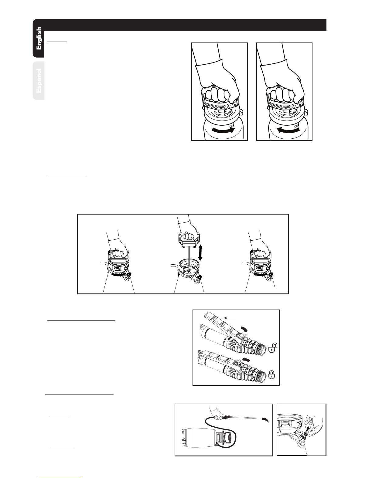
Assemble Extension, Shut-O & Nozzle
1. Install the extension onto the shut-o
assembly and tighten the nut securely.
(See Figure C)
2. Install selected nozzle onto the end of the
extension and tighten securely. (See Figure D)
Figure C
Figure D
ASSEMBLY INSTRUCTIONS
Assemble Hose To Tank
IMPORTANT: Do not attempt to heat or alter hose,
hose nut, or barb prior to assembly.
1. Align hose barb tabs, push hose barb into tank
until it stops (See Figure A).
2. Slide hose nut into place and turn clockwise to
tighten. (See Figure B).
NOTE: Do not use tools to tighten hose nut.
Figure A
Figure B
SELECT USING NOZZLE CHART BELOW
(Nozzle selections vary by model)
A. Cap Nut
B. Foaming Nozzle
C. Adjustable Cone Nozzle
D. Red High-Volume Fan Nozzle
E. Yellow Low-Volume Fan Nozzle
F. Flat Seal
G. Adapter
H. Extension
C
A
G
B
D
F
H
E
ADJUSTABLE CONE USES:
Spot spraying in or around flower
beds, trees, and shrubs.
Edging along fences, driveways,
and walkways.
Killing brush such as poison ivy,
poison oak, kudzu and wild
blackberry.
Preparing garden beds for
planting of ornamentals and
vegetables.
For precision spraying in
confined areas such as
gardens and flower beds.
FAN NOZZLE USES:
Lawn replacement. Kill lawn
and weeds before planting a
new lawn.
Preparing large areas for
planting of ornamental and
vegetable gardens.
RED HIGH VOLUME YELLOW LOW VOLUME
FAN NOZZLE USES:
FOAMING NOZZLE USES:
Spot spraying in flower beds,
walkways, driveways, and
patios, around trees and shrubs.
Edging along fences, driveways
and walkways.
Killing brush such as poison
ivy, poison oak, kudzu and wild
blackberry.
Page 4
OPERATING INSTRUCTIONS
Release Tank Pressure
Pressure Release Valve (PRV) on select models
1. NO PRV: Lay the tank on its side with the hose
outlet on the bottom. Direct the nozzle away
from you and squeeze the shut-o lever until
the unit stops spraying. (See Figure I)
2. WITH PRV: Pull up on the knob of the PRV until
all pressure is released from the tank.
(See Figure J)
Filling
IMPORTANT: Always make sure the pressure is
released from the tank before lling or servicing.
If equipped, pull up on the knob of the pressure
release valve until all the pressure is released
from the tank. Otherwise, squeeze and hold
shut-o lever until the unit stops spraying. Then,
and only then, it is safe to remove pump.
1. Turn the pump handle counterclockwise to remove
the pump (See Figure E).
2. Fill the tank to the desired level. See ll markings
on side of tank. (Always refer to chemical
manufacturer for proper mixture).
3. Install the pump into the tank opening and turn
clockwise until tightly sealed against the tank
(See Figure F).
Figure FFigure E
Pressurizing
1. Make sure shut-o lock is not engaged. (If shut-o lock is engaged while pressurizing, the unit
will immediately start spraying).
2. Push down on the handle and turn counterclockwise to unlock the handle (See Figure G-1G).
3. Pressurize the sprayer by pumping the handle in a smooth up and down motion (See Figure G-2G).
4. Push down on the handle and turn clockwise to lock the handle into the pump (See Figure G-3G).
Figure G
1G 2G
3G
Figure J
Figure I
Spraying and Locking
1. Direct nozzle away from you and squeeze shut-o
lever to begin spraying.
2. For continuous spraying, squeeze lever and rotate
lock (See Figure H).
3. Unlock if needed and release shut-o lever to stop
spraying.
4. Turn the nozzle tip to adjust the spray pattern.
Figure H
LEVER
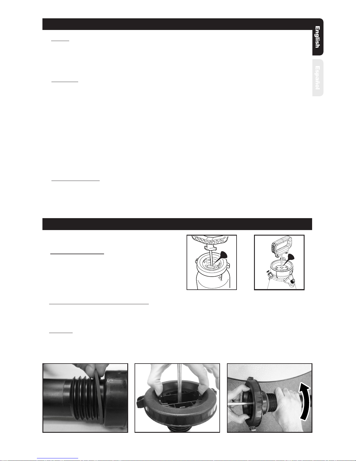
Pump Disassembly & Reassembly
NOTE: Remove pump from tank prior to disassembly.
As shown on varying models.
“O” Style
1. Inspect gasket. If worn or damaged, remove and replace. (See Figure 1)
2. To disassemble pump cap from pump barrel, squeeze the tabs (See Figure 2) that lock the barrel
to the cap, and while resting the extension clip on a table or bench turn the barrel counterclockwise
to unlock. (See Figure 3)
Page 5
Cleaning
1. Remove the pump as described in the Finish section.
2. Fill the tank with cool, clean tap water. Replace the pump and tighten securely.
3. Agitate the tank to rinse the chemical from the tank wall and pump.
4. Remove the pump and empty the contents into gravel or bare soil.
5. Rell the tank with cool, clean tap water.
6. Make sure the pump is free of dirt or debris and reinstall into the tank. Tighten securely.
7. Pressurize the tank as described in the Pressurizing section.
8. Direct the nozzle away from you and activate the shut-o for at least 30 seconds to clean the
hose and shut-o.
9. Release pressure as described in the Release Tank Pressure section.
10. Remove the pump and empty the contents into gravel or bare soil.
11. Repeat steps 5 - 10 until thoroughly cleaned.
Finish
1. Depressurize the tank as described in Release Tank Pressure section.
2. Turn the pump handle counterclockwise to remove the pump.
3. Empty any remaining liquid according to the product disposal directions.
4. Follow the Cleaning instructions.
OPERATING INSTRUCTIONS CONTINUED
Sprayer Storage
1. Sprayer tank should be hung upside down, with the pump removed.
2. Do not store or leave any solution in the tank after use.
3. Store in a warm, dry location out of direct sunlight.
4. Keep the sprayer and all chemicals out of the reach of children.
Figure 3
Figure 1 Figure 2
Pump Lubrication
Pump should be periodically oiled by applying 10 to
12 drops of light oil down the pump rod through the
opening in the pump cap as shown.
MAINTENANCE
“R” Style
“O” Style
Page 6
Nozzle Maintenance
1. If nozzle clogs, remove and disassemble the nozzle assembly.
2. Clean the openings of any obstructions and reassemble.
MAINTENANCE CONTINUED
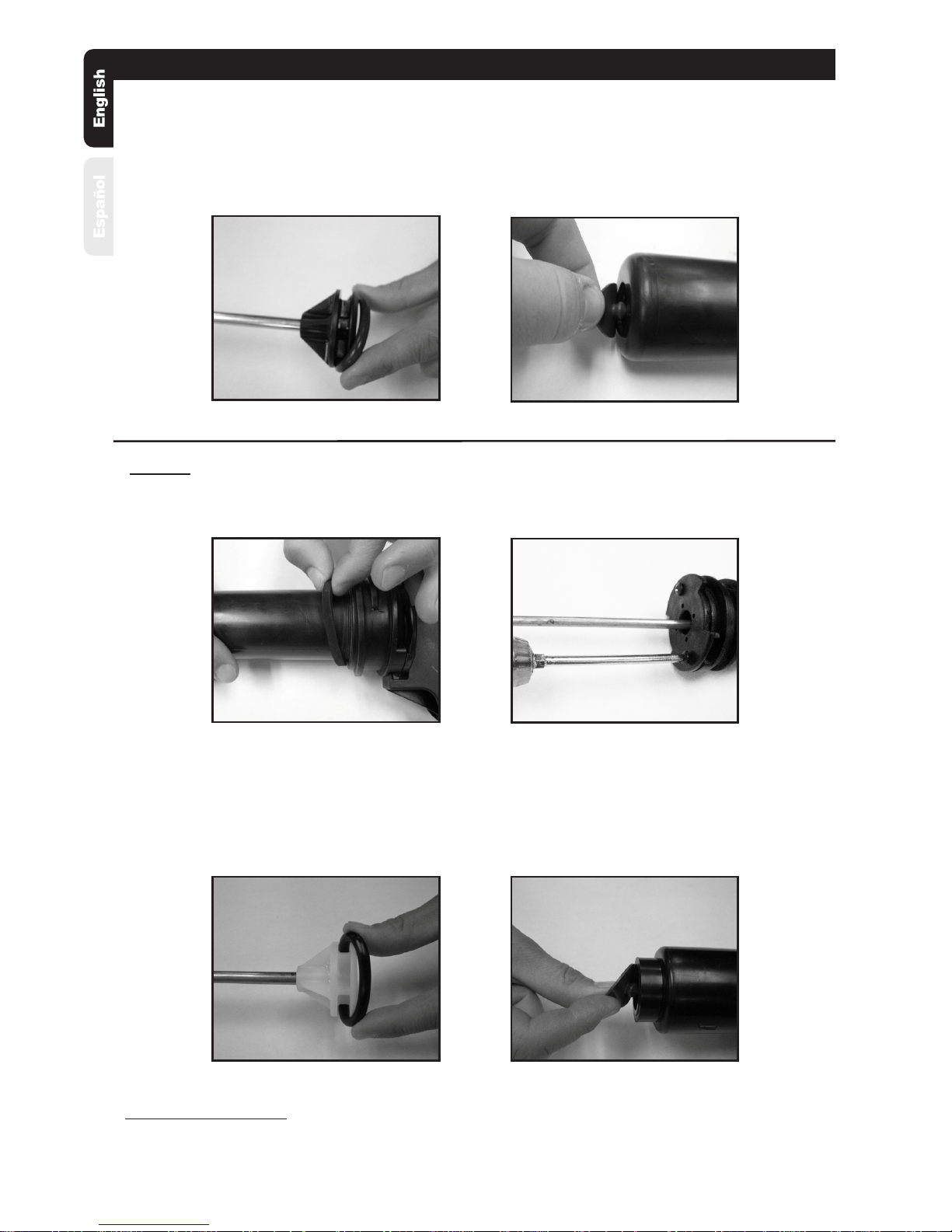
3. Inspect o-ring. If worn or damaged, remove and replace. Lubricate o-ring with petroleum jelly.
(See Figure 4)
4. Inspect check valve in bottom of barrel. If worn or damaged, remove and replace by pressing into
hole in bottom of barrel. (See Figure 5)
5. Re-install the barrel into the cap. While holding the cap securely, turn the barrel clockwise to lock the
tabs in place.
Figure 5
“R” Style
1. Inspect gasket. If worn or damaged, remove and replace. (See Figure 6)
2. To remove pump cap from pump barrel, remove screws securing pump cap to barrel.
(See Figure 7)
3. Inspect o-ring. If worn or damaged, remove and replace. Lubricate o-ring with petroleum jelly.
(See Figure 8)
4. Inspect check valve in bottom of barrel. If worn or damaged, remove and replace by pressing into
hole in bottom of barrel. (See Figure 9)
5. Insert the pump handle assembly into the barrel. Align the holes in the pump cap and barrel. Reinstall
screws and tighten securely.
Figure 7
Figure 6
Figure 8
Figure 9
Figure 4
 Loading...