

Foundry Networks NetIron MLX-4, NetIron MLX-8, NetIron MLX-16, NetIron MLX-32 Installation And Configuration Manual
Page 1

Foundry® NetIron MLX Series
Installation and Basic Configuration
Guide
NetIron MLX-4
NetIron MLX-8
NetIron MLX-16
NetIron MLX-32
Release 04.0.00
Release Date: December 17, 2008
Publish Date: December 31, 2008
Page 2

Copyright © 2008 Foundry Networks, Inc. All rights reserved.
No part of this work may be reproduced in any form or by any means – graphic, electronic or mechanical, including
photocopying, recording, taping or storage in an information retrieval system – without prior written permission of the
copyright owner.
The trademarks, logos and service marks ("Marks") displayed herein are the property of Foundry® or other third
parties. You are not permitted to use these Marks without the prior written consent of Foundry or such appropriate third
party.
Foundry Networks, BigIron, Terathon, FastIron, IronView, JetCore, NetIron, SecureIron, ServerIron, Tu r b o Ir o n ,
IronWare, EdgeIron, IronPoint, the Iron family of marks and the Foundry Logo are trademarks or registered trademarks
of Foundry Networks, Inc. in the United States and other countries.
F-Secure is a trademark of F-Secure Corporation. All other trademarks mentioned in this document are the property of
their respective owners.
Foundry Networks
4980 Great America Parkway
Santa Clara, CA 95054
Tel 408.207.1700
www.foundrynetworks.com
Page 3

Contents
CHAPTER 1
ETTING STARTED...................................................................................... 1-1
G
INTRODUCTION ...........................................................................................................................................1-1
A
UDIENCE ..................................................................................................................................................1-1
N
OMENCLATURE .........................................................................................................................................1-1
U
PDATES TO MANUALS ...............................................................................................................................1-1
H
OW TO GET HELP OR REPORT ERRORS ....................................................................................................1-2
W
EB ACCESS .......................................................................................................................................1-2
E
MAIL ACCESS .....................................................................................................................................1-2
T
ELEPHONE ACCESS ............................................................................................................................1-2
W
ARRANTY COVERAGE ...............................................................................................................................1-2
CHAPTER 2
RODUCT OVERVIEW .................................................................................. 2-1
P
PRODUCT OVERVIEW ..................................................................................................................................2-1
N
ETIRON MLX SERIES ROUTER APPLICATIONS ...........................................................................................2-2
H
ARDWARE FEATURES ...............................................................................................................................2-2
C
HASSIS ..............................................................................................................................................2-2
N
ETIRON MLX-4 ........................................................................................................................... 2-6
N
ETIRON MLX-8 ........................................................................................................................... 2-6
N
ETIRON MLX-16 ......................................................................................................................... 2-6
N
ETIRON MLX-32 ......................................................................................................................... 2-7
M
ANAGEMENT MODULES ......................................................................................................................2-7
PCMCIA S
C
ONSOLE PORT............................................................................................................................. 2-8
10/100/1000 E
LED
I
NTERFACE MODULES .........................................................................................................................2-10
10 G
FE/G
10/100/1000 E
1 G
IGABIT X 48-T MODULE .......................................................................................................... 2-14
December 2008 © 2008 Foundry Networks, Inc. -iii
LOTS............................................................................................................................ 2-8
THERNET PORT ...................................................................................................... 2-8
S............................................................................................................................................ 2-9
IGABIT ETHERNET INTERFACE MODULES (2-PORT AND 4-PORT) ............................................. 2-10
BE (100/1000) ETHERNET INTERFACE MODULE (SFP)......................................................... 2-12
THERNET INTERFACE MODULE (RJ-45) ................................................................. 2-14
Page 4

Foundry NetIron MLX Series Installation and Basic Configuration Guide
POS INTERFACE MODULES ................................................................................................................2-15
D
UAL SPEED OC-12C AND OC-48C............................................................................................. 2-15
S
INGLE-SPEED OC-192C ............................................................................................................ 2-16
LED O
OC-12
OC-192
C
S
WITCH FABRIC MODULE ...................................................................................................................2-20
P
OWER SUPPLIES ..............................................................................................................................2-22
B
UILT-IN MOUNTING BRACKETS ..........................................................................................................2-23
C
OOLING SYSTEM ..............................................................................................................................2-23
R
ACK MOUNT KIT ..............................................................................................................................2-27
S
UPPORTED SOFTWARE FEATURES ...........................................................................................................2-27
PERATION ......................................................................................................................... 2-17
C AND OC-48C PORTS...................................................................................................... 2-18
C PORTS......................................................................................................................... 2-19
LOCKING AND TIMING A POS INTERFACE MODULE...................................................................... 2-19
CHAPTER 3
INSTALLING A NETIRON MLX SERIES ROUTER ............................................ 3-1
INSTALLATION PRECAUTIONS ................................................................................................................3-1
G
ENERAL PRECAUTIONS ................................................................................................................ 3-1
P
OWER PRECAUTIONS .........................................................................................................................3-2
I
NSTALLING A NETIRON MLX-4 ROUTER ......................................................................................................3-4
P
REPARING THE INSTALLATION SITE .....................................................................................................3-4
C
ABLING INFRASTRUCTURE ............................................................................................................ 3-4
I
NSTALLATION LOCATION................................................................................................................ 3-4
U
NPACKING A NETIRON MLX-4 ROUTER ...............................................................................................3-4
C
HASSIS LIFTING GUIDELINES FOR NETIRON MLX-4 ROUTERS ..............................................................3-5
I
NSTALLING A NETIRON MLX-4 CHASSIS IN A RACK ..............................................................................3-5
P
REPARING TO MOUNT A NETIRON MLX-4 CHASSIS IN A RACK ...................................................... 3-5
R
EMOVING NETIRON MLX-4 EXTRA SHIPMENT SCREWS................................................................. 3-5
M
OUNTING A NETIRON MLX-4 CHASSIS IN A RACK......................................................................... 3-5
R
EMOVING THE SLOT BLANKS........................................................................................................ 3-7
I
NSTALLING NETIRON MLX-4 MODULES ................................................................................................3-7
I
NSTALLING POWER SUPPLIES IN A NETIRON MLX-4 CHASSIS ...............................................................3-9
C
ONNECTING AC POWER TO A NETIRON MLX-4 CHASSIS .....................................................................3-9
C
ONNECTING DC POWER TO A NETIRON MLX-4 CHASSIS ..................................................................3-10
F
INAL STEPS ......................................................................................................................................3-11
I
NSTALLING A NETIRON MLX-8 ROUTER ....................................................................................................3-12
P
REPARING THE INSTALLATION SITE ...................................................................................................3-12
C
ABLING INFRASTRUCTURE .......................................................................................................... 3-12
I
NSTALLATION LOCATION.............................................................................................................. 3-12
U
NPACKING A NETIRON MLX-8 ROUTER .............................................................................................3-12
C
HASSIS LIFTING GUIDELINES FOR NETIRON MLX-8 ROUTERS ............................................................3-13
I
NSTALLING THE NETIRON MLX-8 CHASSIS IN A RACK .........................................................................3-13
P
REPARING TO MOUNT A NETIRON MLX-8 CHASSIS IN A RACK .................................................... 3-13
R
EMOVING NETIRON MLX-8 EXTRA SHIPMENT SCREWS............................................................... 3-13
M
OUNTING A NETIRON MLX-8 CHASSIS IN A RACK....................................................................... 3-13
R
EMOVING THE SLOT BLANKS...................................................................................................... 3-15
I
NSTALLING NETIRON MLX-8 MODULES ..............................................................................................3-15
I
NSTALLING POWER SUPPLIES IN THE NETIRON MLX-8 CHASSIS .........................................................3-17
C
ONNECTING AC POWER TO A NETIRON MLX-8 CHASSIS ...................................................................3-17
-iv © 2008 Foundry Networks, Inc. December 2008
Page 5

Contents
CONNECTING DC POWER TO A NETIRON MLX-8 CHASSIS ..................................................................3-18
F
INAL STEPS ......................................................................................................................................3-19
I
NSTALLING A NETIRON MLX-16 ROUTER ..................................................................................................3-20
P
REPARING THE INSTALLATION SITE ...................................................................................................3-20
C
ABLING INFRASTRUCTURE .......................................................................................................... 3-20
I
NSTALLATION LOCATION.............................................................................................................. 3-20
U
NPACKING A NETIRON MLX-16 ROUTER ...........................................................................................3-20
C
HASSIS LIFTING GUIDELINES FOR NETIRON MLX-16 ROUTERS ..........................................................3-21
I
NSTALLING A CHASSIS IN A RACK .......................................................................................................3-21
P
REPARING TO MOUNT A NETIRON MLX-16 CHASSIS IN A RACK .................................................. 3-21
A
TTACHING MOUNTING BRACKETS TO A NETIRON MLX-16 CHASSIS ............................................. 3-21
M
OUNTING A NETIRON MLX-16 CHASSIS IN A RACK..................................................................... 3-22
R
EMOVING THE SLOT BLANKS...................................................................................................... 3-23
I
NSTALLING NETIRON MLX-16 MODULES ............................................................................................3-23
P
OPULATING A NETIRON MLX-16 CHASSIS .................................................................................. 3-25
R
ULES FOR POPULATING A NETIRON MLX-16 CHASSIS ................................................................ 3-25
I
NSTALLING POWER SUPPLIES IN A NETIRON MLX-16 CHASSIS ...........................................................3-25
C
ONNECTING AC POWER TO A NETIRON MLX-16 CHASSIS .................................................................3-26
C
ONNECTING DC POWER TO A NETIRON MLX-16 CHASSIS ................................................................3-27
F
INAL STEPS ......................................................................................................................................3-28
I
NSTALLING A NETIRON MLX-32 ROUTER ..................................................................................................3-29
P
REPARING THE INSTALLATION SITE ...................................................................................................3-29
C
ABLING INFRASTRUCTURE .......................................................................................................... 3-29
I
NSTALLATION LOCATION.............................................................................................................. 3-29
U
NPACKING A NETIRON MLX-32 ROUTER ...........................................................................................3-29
U
NCRATING THE NETIRON MLX-32 CHASSIS................................................................................ 3-30
I
NSTALLING A NETIRON MLX-32 CHASSIS IN A RACK ..........................................................................3-31
P
REPARING TO MOUNT A NETIRON MLX-32 CHASSIS IN A RACK .................................................. 3-31
A
TTACHING MOUNTING BRACKETS TO A NETIRON MLX-16 OR
N
ETIRON MLX-32 CHASSIS ............................................................................................ 3-31
M
OUNTING A NETIRON MLX-32 CHASSIS IN A RACK..................................................................... 3-31
I
NSTALLING NETIRON MLX-32 MODULES ............................................................................................3-33
N
ETIRON MLX-32 MODULE INSTALLATION DETAILS ...................................................................... 3-34
U
SING THE INSERTION/EXTRACTION TOOL .................................................................................... 3-35
N
ETIRON MLX-32 CABLE MANAGEMENT .............................................................................................3-36
C
ABLE ROUTING FOR THE UPPER-LEFT QUADRANT....................................................................... 3-38
C
ABLE ROUTING FOR THE UPPER-RIGHT QUADRANT..................................................................... 3-40
C
ABLE ROUTING FOR THE LOWER-LEFT QUADRANT. ..................................................................... 3-42
C
ABLE ROUTING FOR THE LOWER-RIGHT QUADRANT. ................................................................... 3-44
I
NSTALLING POWER SUPPLIES IN A NETIRON MLX-32 CHASSIS .................................................................3-45
C
ONNECTING AC POWER TO A NETIRON MLX-32 CHASSIS .................................................................3-46
C
ONNECTING DC POWER TO A NETIRON MLX-32 CHASSIS ................................................................3-47
F
INAL STEPS ......................................................................................................................................3-49
A
TTACHING A MANAGEMENT STATION .......................................................................................................3-49
A
TTACHING A PC OR TERMINAL TO THE CONSOLE PORT OR ETHERNET PORT .....................................3-50
A
TTACHING THE MANAGEMENT MODULE’S ETHERNET PORT TO A NETWORK ........................................3-50
P
OWERING-ON THE POWER SOURCE ........................................................................................................3-50
V
ERIFYING PROPER OPERATION ...............................................................................................................3-51
O
BSERVING THE LEDS .......................................................................................................................3-51
December 2008 © 2008 Foundry Networks, Inc. -v
Page 6

Foundry NetIron MLX Series Installation and Basic Configuration Guide
DISPLAYING THE MODULE STATUS ......................................................................................................3-57
CHAPTER 4
ONNECTING A NETIRON MLX SERIES ROUTER
C
TO A NETWORK DEVICE .............................................................................. 4-1
ASSIGNING PERMANENT PASSWORDS .........................................................................................................4-1
C
ONFIGURING IP ADDRESSES .....................................................................................................................4-2
S
UPPORT OF SUB-NET MASKS .............................................................................................................4-3
A
SSIGNING AN IP ADDRESS TO A MANAGEMENT INTERFACE ..................................................................4-3
A
SSIGNING AN IP ADDRESS TO AN INTERFACE, VIRTUAL INTERFACE, OR LOOPBACK ...............................4-4
E
NABLING AND DISABLING THE INTERFACES ..........................................................................................4-5
U
NDERSTANDING HOW THE MANAGEMENT PORT FUNCTIONS .......................................................................4-5
C
ONNECTING A NETIRON MLX SERIES ROUTER .........................................................................................4-5
I
NSTALLING A FIBER-OPTIC MODULE .....................................................................................................4-5
C
ABLING A FIBER-OPTIC MODULE .........................................................................................................4-6
C
LEANING FIBER-OPTIC MODULES ........................................................................................................4-6
T
ROUBLESHOOTING NETWORK CONNECTIONS .......................................................................................4-6
T
ESTING NETWORK CONNECTIVITY ..............................................................................................................4-8
P
INGING AN IP ADDRESS ......................................................................................................................4-8
T
RACING A ROUTE ...............................................................................................................................4-8
CHAPTER 5
ANAGING THE NETIRON MLX SERIES
M
HASSIS AND MODULES ............................................................................. 5-1
C
MANAGING THE NETIRON MLX SERIES CHASSIS .........................................................................................5-1
D
ISPLAYING CHASSIS STATUS AND TEMPERATURE READINGS ................................................................5-1
D
ISPLAYING THE SYSLOG CONFIGURATION AND STATIC AND DYNAMIC BUFFERS ....................................5-4
S
TATIC AND DYNAMIC BUFFERS ..................................................................................................... 5-5
M
ANAGING THE COOLING SYSTEM ..............................................................................................................5-6
C
ONFIGURING THE COOLING SYSTEM ...................................................................................................5-6
C
HANGING TEMPERATURE THRESHOLDS FOR MODULES AND FAN SPEEDS...................................... 5-6
C
HANGING THE TEMPERATURE POLLING INTERVAL ....................................................................... 5-11
M
ANUALLY SETTING THE FAN SPEED ..................................................................................................5-11
M
ONITORING THE COOLING SYSTEM ...................................................................................................5-12
D
ISPLAYING FAN TRAY STATUS AND SPEED ................................................................................. 5-12
D
ISPLAYING TEMPERATURE WARNINGS ....................................................................................... 5-12
T
EMPERATURE LOG REDUCTION .........................................................................................................5-13
C
ONFIGURING TEMPERATURE LOGGING........................................................................................ 5-13
M
ANAGING THE INTERFACE MODULES .......................................................................................................5-13
C
ONFIGURING INTERFACE MODULE BOOT PARAMETERS ......................................................................5-14
S
YNCHRONIZING THE INTERFACE MODULE’S MULTI-SERVICE IRONWARE IMAGES BETWEEN
M
ANAGEMENT AND INTERFACE MODULES ........................................................................ 5-14
C
HANGING THE BOOT SOURCE .................................................................................................... 5-15
C
HANGING PRIORITY OF CHASSIS SLOTS FOR INTERFACE MODULES ....................................................5-18
D
ISABLING AND REENABLING POWER TO THE INTERFACE MODULES .....................................................5-19
E
NABLING AND DISABLING MANAGEMENT MODULE CPU USAGE CALCULATIONS .........................................5-19
D
ISPLAYING CPU USAGE ...................................................................................................................5-20
-vi © 2008 Foundry Networks, Inc. December 2008
Page 7

Contents
DISPLAYING MANAGEMENT MODULE CPU USAGE .....................................................................................5-21
E
NABLING AND DISABLING PACKET LOGGING FOR MANAGEMENT AND INTERFACE MODULES .......................5-21
D
ISPLAYING A PACKET LOG ................................................................................................................5-22
R
EMOVING MAC ADDRESS ENTRIES .........................................................................................................5-24
CHAPTER 6
MAINTAINING A NETIRON MLX SERIES ROUTER ..........................................6-1
HARDWARE MAINTENANCE SCHEDULE .........................................................................................................6-1
C
LEANING THE FIBER-OPTIC CONNECTORS .................................................................................................6-2
R
EPLACING A MANAGEMENT MODULE .........................................................................................................6-2
R
EMOVING A MANAGEMENT MODULE ....................................................................................................6-2
I
NSTALLING A NEW MANAGEMENT MODULE ...........................................................................................6-3
R
EPLACING AN INTERFACE MODULE ............................................................................................................6-3
R
EMOVING AN INTERFACE MODULE .......................................................................................................6-4
I
NSTALLING A NEW INTERFACE MODULE ................................................................................................6-4
R
EPLACING A SWITCH FABRIC MODULE .......................................................................................................6-8
R
EMOVING A SWITCH FABRIC MODULE .................................................................................................6-8
I
NSTALLING A NEW SWITCH FABRIC MODULE ........................................................................................6-8
R
EPLACING A FIBER-OPTIC TRANSCEIVER ...................................................................................................6-9
R
EMOVING A FIBER-OPTIC TRANSCEIVER ..............................................................................................6-9
I
NSTALLING A NEW FIBER-OPTIC TRANSCEIVER .....................................................................................6-9
C
ABLING A FIBER-OPTIC TRANSCEIVER ...............................................................................................6-10
R
EPLACING A POWER SUPPLY ..................................................................................................................6-10
D
ETERMINING WHICH POWER SUPPLY FAILED ....................................................................................6-10
S
ETTING THE THRESHOLD FOR POWER SUPPLY MONITORING ..............................................................6-10
C
LEARING POWER SUPPLY FAILURE TIMESTAMPS ...............................................................................6-11
D
ISPLAYING POWER SUPPLY MONITORING TIMESTAMPS ......................................................................6-11
E
NABLING A POWER SUPPLY SHUTDOWN ............................................................................................6-11
P
OWERING ON THE POWER SUPPLY THROUGH THE CLI ......................................................................6-12
R
EPLACING A POWER SUPPLY ............................................................................................................6-12
R
EPLACING FAN ASSEMBLIES ....................................................................................................................6-14
R
EPLACING FAN ASSEMBLIES IN THE NETIRON MLX-32 ......................................................................6-14
R
EPLACING FAN ASSEMBLIES IN THE NETIRON MLX-16 ......................................................................6-15
R
EPLACING THE REAR FAN ASSEMBLIES IN THE NETIRON MLX-16 ............................................... 6-16
R
EPLACING THE FRONT FAN ASSEMBLY IN THE NETIRON MLX-16 ................................................ 6-17
R
EPLACING THE FAN TRAY ASSEMBLY IN THE NETIRON MLX-4 AND NETIRON MLX-8 ..........................6-17
R
EPLACING THE AIR FILTERS IN A NETIRON MLX SERIES ROUTER ......................................................6-19
R
EPLACING THE AIR FILTERS IN THE NETIRON MLX-32 ................................................................ 6-19
R
EPLACING THE AIR FILTER IN THE NETIRON MLX-16 .................................................................. 6-21
R
EPLACING THE AIR FILTER IN THE NETIRON MLX-4 OR NETIRON MLX-8..................................... 6-22
CHAPTER 7
PGRADING SOFTWARE IMAGES AND CONFIGURATION FILES....................... 7-1
U
SNMP ON SYSTEMS WITH NI-MLX-1GX48-T MODULES ..............................................................................7-2
S
OFTWARE IMAGES REQUIRED ....................................................................................................................7-2
I
MAGES AND PROCEDURES REQUIRED ..................................................................................................7-3
December 2008 © 2008 Foundry Networks, Inc. -vii
Page 8

Foundry NetIron MLX Series Installation and Basic Configuration Guide
DESCRIPTION OF THE SOFTWARE IMAGES REQUIRED ............................................................................7-3
U
PGRADING SOFTWARE IMAGES AS REQUIRED BY VERSION ..................................................................7-4
U
PGRADING TO VERSION 03.5.00 (OR LATER) FROM A PRE-03.5.00 VERSION................................. 7-4
D
OWNGRADING FROM VERSION 03.5.00 (OR LATER) TO A PRE-03.5.00 VERSION ............................ 7-5
U
PGRADING FROM VERSION 03.5.00 (OR LATER) TO A LATER VERSION........................................... 7-5
D
ISPLAYING FLASH MEMORY AND VERSION INFORMATION .....................................................................7-6
D
ISPLAYING FLASH INFORMATION ................................................................................................... 7-6
D
ISPLAYING VERSION INFORMATION ............................................................................................. 7-11
U
PGRADING THE MANAGEMENT MODULE’S MONITOR AND BOOT IMAGES .............................................7-14
U
PGRADING THE MANAGEMENT MODULE’S IRONWARE IMAGE .............................................................7-15
U
PGRADING THE INTERFACE MODULE’S MONITOR AND BOOT IMAGES ..................................................7-17
U
PGRADING THE INTERFACE MODULE’S IRONWARE IMAGE ..................................................................7-18
U
PGRADING THE MANAGEMENT AND INTERFACE MODULE IRONWARE IMAGES TOGETHER ....................7-18
U
PGRADING MBRIDGE FPGA ON THE MANAGEMENT MODULE ..........................................................7-19
O
VERVIEW OF TASKS IN THE FPGA IMAGE UPGRADE PROCESS ................................................... 7-19
D
ETERMINING THE MBRIDGE IMAGE VERSIONS........................................................................... 7-19
U
PGRADING THE MBRIDGE FPGA IMAGE................................................................................... 7-20
U
PGRADING AN FPGA FOR AN INTERFACE MODULE ............................................................................7-20
O
VERVIEW OF TASKS IN THE FPGA IMAGE UPGRADE PROCESS ................................................... 7-21
D
ETERMINING THE FPGA IMAGE VERSIONS.................................................................................. 7-21
U
PGRADING ALL FPGA IMAGES FOR ALL INTERFACE MODULES AT THE SAME TIME ..............................7-24
U
PGRADING ALL LP FPGA IMAGES AT THE SAME TIME ................................................................ 7-24
U
PGRADING THE FPGA IMAGES ONE IMAGE AT A TIME................................................................. 7-24
R
EBOOTING THE MANAGEMENT MODULE ............................................................................................7-26
H
ITLESS OS UPGRADE .......................................................................................................................7-27
C
ONSIDERATIONS WHEN USING THE FEATURE .............................................................................. 7-28
T
HE HITLESS OS SOFTWARE PROCESS ....................................................................................... 7-29
P
ERFORMING A HITLESS OS SOFTWARE UPGRADE, ..................................................................... 7-31
L
OADING THE MULTI-SERVICE IRONWARE SOFTWARE ONTO THE ROUTER..................................... 7-31
S
ETTING UP CONSOLES ............................................................................................................... 7-31
E
XECUTING THE HITLESS UPGRADE COMMAND............................................................................. 7-31
L
OADING AND SAVING CONFIGURATION FILES ............................................................................................7-31
C
ONFIGURING FILE SIZE FOR STARTUP AND RUNNING CONFIGURATION ...............................................7-32
R
EPLACING THE STARTUP CONFIGURATION WITH THE RUNNING CONFIGURATION .................................7-32
R
EPLACING THE RUNNING CONFIGURATION WITH THE STARTUP CONFIGURATION .................................7-32
C
OPYING A CONFIGURATION FILE TO OR FROM A TFTP SERVER ........................................................7-33
M
AKING LOCAL COPIES OF THE STARTUP CONFIGURATION FILE ..........................................................7-33
D
YNAMIC CONFIGURATION LOADING ..........................................................................................................7-33
U
SAGE CONSIDERATIONS............................................................................................................. 7-33
P
REPARING THE CONFIGURATION FILE ......................................................................................... 7-34
L
OADING THE CONFIGURATION INFORMATION INTO THE RUNNING-CONFIG ...........................................7-35
U
SING SNMP TO SAVE AND LOAD CONFIGURATION INFORMATION .............................................................7-35
E
RASING IMAGE AND CONFIGURATION FILES ..............................................................................................7-36
F
ILE SYNCHRONIZATION ............................................................................................................................7-36
F
ILE SYNCHRONIZATION BETWEEN THE ACTIVE AND STANDBY MANAGEMENT MODULES .......................7-36
C
OMPARING AND SYNCHRONIZING FILES ...................................................................................... 7-37
S
YNCHRONIZING FILES WITHOUT COMPARISON ............................................................................ 7-37
F
ILE SYNCHRONIZATION BETWEEN THE MANAGEMENT AND INTERFACE MODULES ................................7-37
S
YNCHRONIZING THE INTERFACE MODULES IRONWARE IMAGES DURING BOOTUP ......................... 7-38
-viii © 2008 Foundry Networks, Inc. December 2008
Page 9

Contents
SPECIFYING AN IMMEDIATE SYNCHRONIZATION ............................................................................. 7-38
S
CHEDULING A SYSTEM RELOAD ...............................................................................................................7-38
R
ELOADING AT A SPECIFIC TIME .........................................................................................................7-38
R
ELOADING AFTER A SPECIFIC AMOUNT OF TIME ................................................................................7-38
D
ISPLAYING THE AMOUNT OF TIME REMAINING BEFORE A SCHEDULED RELOAD ...................................7-39
C
ANCELING A SCHEDULED RELOAD ....................................................................................................7-39
D
IAGNOSTIC ERROR CODES AND REMEDIES FOR TFTP TRANSFERS ..........................................................7-39
CHAPTER 8
ARDWARE SPECIFICATIONS....................................................................... 8-1
H
HARDWARE SPECIFICATIONS .......................................................................................................................8-1
P
OWER SPECIFICATIONS ......................................................................................................................8-1
P
HYSICAL DIMENSIONS .........................................................................................................................8-3
O
PERATING ENVIRONMENT ........................................................................................................................8-4
S
TORAGE ENVIRONMENT .....................................................................................................................8-4
S
AFETY AGENCY APPROVALS ...............................................................................................................8-4
E
LECTROMAGNETIC APPROVALS ...........................................................................................................8-4
P
ORT SPECIFICATIONS ................................................................................................................................8-5
C
ONSOLE PORT PIN ASSIGNMENTS ......................................................................................................8-5
M
ANAGEMENT PORT PIN ASSIGNMENTS ................................................................................................8-6
APPENDIX A
EGULATORY STATEMENTS ........................................................................A-1
R
U.S.A. ...................................................................................................................................................... A-1
I
NDUSTRY CANADA STATEMENT ................................................................................................................. A-1
E
UROPE AND AUSTRALIA ........................................................................................................................... A-1
G
ERMANY ................................................................................................................................................. A-1
J
APAN ....................................................................................................................................................... A-2
K
OREA ...................................................................................................................................................... A-2
APPENDIX B
AUTIONS AND WARNINGS..........................................................................B-1
C
CAUTIONS ................................................................................................................................................. B-1
W
ARNINGS .............................................................................................................................................. B-11
December 2008 © 2008 Foundry Networks, Inc. -ix
Page 10

Foundry NetIron MLX Series Installation and Basic Configuration Guide
-x © 2008 Foundry Networks, Inc. December 2008
Page 11

Chapter 1
Getting Started
Introduction
This guide describes the NetIron MLX router from Foundry Networks. It provides procedures for installing modules
into the NetIron MLX Series chassis, cabling the Ethernet interface ports, and performing a basic configuration of
the software. This guide also explains how to perform tasks using the command line interface (CLI).
Audience
This guide is designed for network installers, system administrators, and resellers who will install and perform a
basic software configuration for the NetIron MLX Series router. This guide assumes a working knowledge of Layer
2 and Layer 3 switching and routing concepts.
Nomenclature
This guide uses the following typographical conventions to show information:
Italic highlights the title of another publication and occasionally emphasizes a word or phrase.
Bold highlights a CLI command.
Bold Italic highlights a term that is being defined.
NOTE: A note emphasizes an important fact or calls your attention to a dependency.
WARNING: A warning calls your attention to a possible hazard that can cause injury or death.
CAUTION: A caution calls your attention to a possible hazard that can damage equipment.
Updates to Manuals
Manuals for this product may be updated between releases. For the latest edition of manuals, check the Foundry
Knowledge Portal at kp.foundrynet.com.
December 2008 © 2008 Foundry Networks, Inc. 1-1
Page 12

Foundry NetIron MLX Series Installation and Basic Configuration Guide
How to Get Help or Report Errors
Foundry Networks is committed to ensuring that your investment in our products remains cost-effective. If you
need assistance, or find errors in the manuals, contact Foundry Networks using one of the following options:
Web Access
If you find errors in this document, please report the error by going to kp.foundrynet.com. After you login in, click
Cases > Create a New Ticket. Make sure you specify the document title in the ticket description.
Email Access
Send an e-mail to support@foundrynet.com.
Telephone Access
1.877.TURBOCALL (887.2622) United States
1.408.207.1600Outside the United States
Warranty Coverage
Contact Foundry Networks using any of the methods listed above for information about the standard and extended
warranties.
1-2 © 2008 Foundry Networks, Inc. December 2008
Page 13

Chapter 2
Product Overview
The NetIron MLX Series router provides high-performance routing for service providers, metro topologies, and
Internet Exchange Points. This chapter provides an overview of Foundry’s NetIron MLX Series routers. It provides
the following information:
• Overview of the benefits the NetIron MLX Series router offers
• Network topologies in which a NetIron MLX Series router will be commonly deployed
• The NetIron MLX Series router hardware and how each major hardware component functions
• Software features that the NetIron MLX Series router supports
• The NetIron MLX Series router’s architecture, how it differs from other Layer 3 router architectures, and how
you will benefit from the differences
Product Overview
The NetIron MLX Series router provides the following benefits:
• The ability of the 10 Gigabit Ethernet ports to process both inbound and outbound user packets at a full
10Gbps, thereby delivering true wire-speed performance
• IPv4 routing with very large hardware-based forwarding table and powerful hardware-based ACL and rate
limiting functions
• IPv6 routing with a rich feature set including hardware-based forwarding, and dual-stack support
• High availability (redundancy) of the following NetIron MLX Series router critical components:
• Management modules
• Fans
• Power supplies
• Switch fabric module
Each of these components, along with the interface modules, is hot swappable, which means you can remove
and replace them while the NetIron MLX Series chassis is powered on and running.
• Completely separate data and control planes, which results in uncompromised switching performance,
increased reliability of both planes, and increased security of the control plane in the event of a Denial of
Service attack (DoS) on the data plane
• Distributed data and control planes, which results in uncompromised wire-speed performance for the data
plane and faster and more efficient performance of management functions for the control plane
December 2008 © 2008 Foundry Networks, Inc. 2-1
Page 14

Foundry NetIron MLX Series Installation and Basic Configuration Guide
• A management (10BaseT/100BaseTX/1000BaseTX Ethernet) port that can provide connectivity to your
existing management network
• Increased amount of TCAM on the interface modules, which accommodates the processing of more software
functions such as those related to routing protocols
• Increased amounts of processor RAM on the management and interface modules, which allows larger default
table sizes for the MAC address table, the IP route table, and so on
• Airflow that circulates from the front to the back of the NetIron MLX Series router chassis, which directs hot air
from the chassis away from other racks of equipment rather than toward them
NetIron MLX Series Router Applications
The NetIron MLX Series router is commonly deployed in the following situations:
• Layer 2 metro networks
• MPLS Layer-3 VPN service provider networks supporting multi-VRFs and RFC 2547bis
• MPLS Layer-2 VPN service provider networks supporting both VPLS and VLL
Hardware Features
This chapter covers the following major hardware components of NetIron MLX Series routers:
• “Chassis”
• “Management Modules”
• “Interface Modules”
• “Switch Fabric Module”
• “Power Supplies”
• “Cooling System”, which is composed of temperature sensors, fans, fan control modules, and an air filter
• “Rack Mount Kit”
The following sections provide more information about these components.
Chassis
The NetIron MLX Series chassis consists of the following four chassis:
• NetIron MLX-4: Provides 4 interface slots
• NetIron MLX-8: Provides 8 interface slots
• NetIron MLX-16: Provides 16 interface slots
• NetIron MLX-32: Provides 32 interface slots
The following figures illustrate the NetIron MLX Series chassis.
2-2 © 2008 Foundry Networks, Inc. December 2008
Page 15
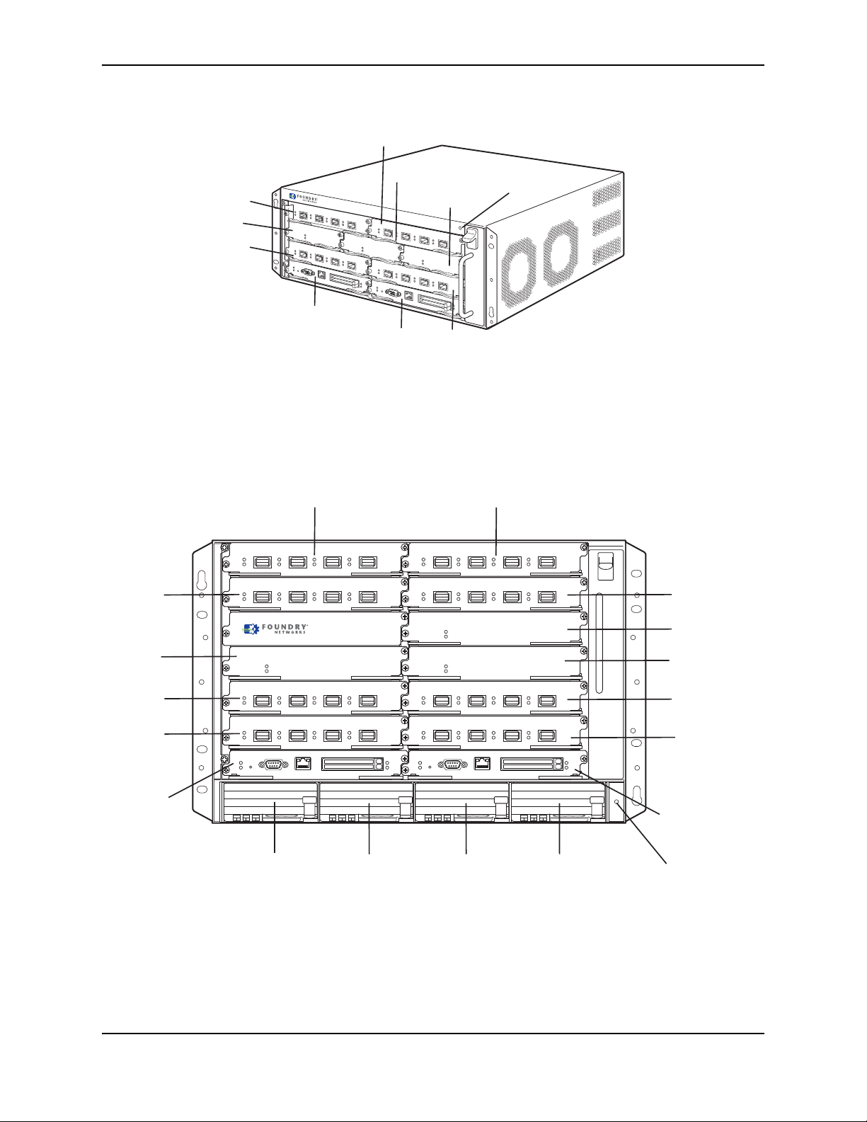
Figure 2.1 NetIron MLX-4 Chassis
Switch Fabric
Slot 3
Interface
Slot 1
Interface
Slot 2
Interface
Slot 3
Interface
Slot 4
Switch Fabric
Slot 1
Switch Fabric
Slot 2
Management
Slot 1
Management
Slot 2
ESD Connector
NetIron MLX 8
Interface
Slot 1
Interface
Slot 2
Interface
Slot 4
Switch
Fabric
Slot 1
Switch
Fabric
Slot 3
Interface
Slot 6
Interface
Slot 8
Management
Slot 2
Interface
Slot 3
Switch
Fabric
Slot 2
Interface
Slot 5
Interface
Slot 7
Management
Slot 1
Power Supply
Slot 1
Power Supply
Slot 2
Power Supply
Slot 3
Power Supply
Slot 4
ESD
Connector
Figure 2.2 NetIron MLX-8 Chassis
Product Overview
December 2008 © 2008 Foundry Networks, Inc. 2-3
Page 16
Foundry NetIron MLX Series Installation and Basic Configuration Guide
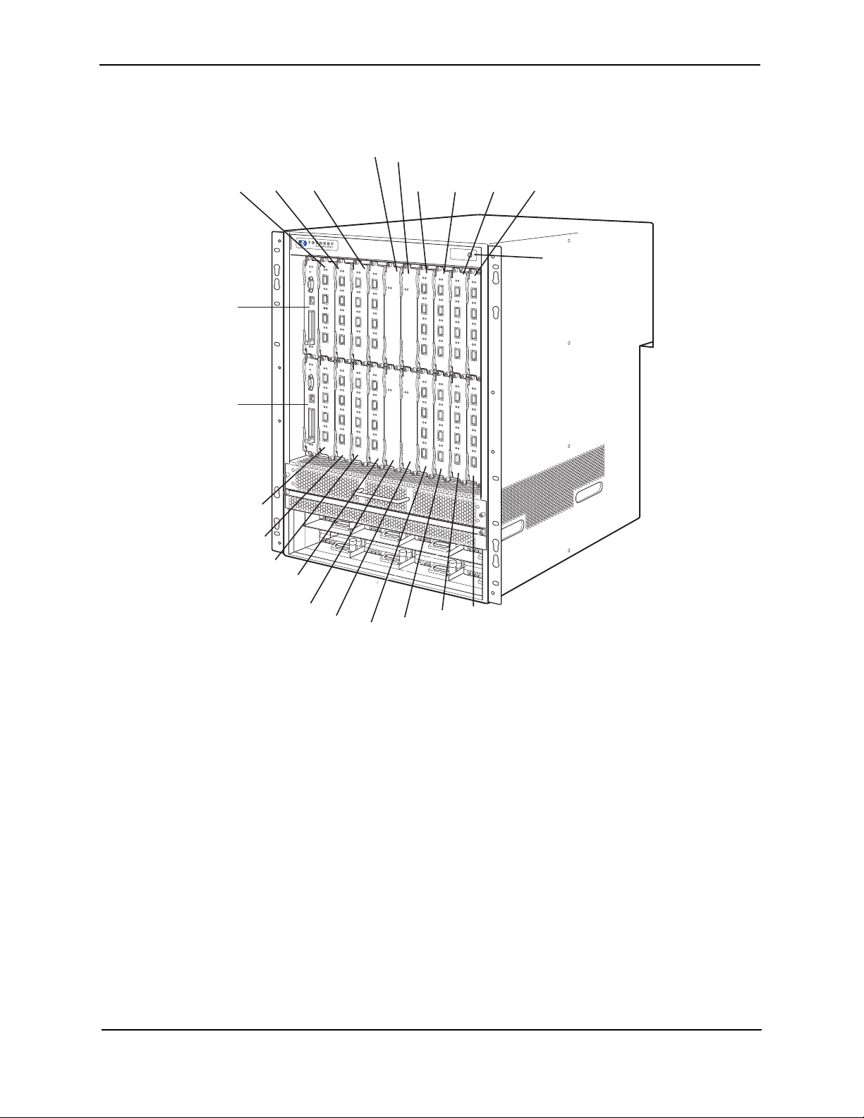
Management
Slot 1
Management
Slot 2
NetIron MLX 16
Interface
Slot 1
Interface
Slot 3
Interface
Slot 5
Interface
Slot 7
Switch
Fabric
Slot 1
Switch
Fabric
Slot 3
Interface
Slot 9
Interface
Slot 11
Interface
Slot 13
Interface
Slot 15
Interface
Slot 2
Interface
Slot 4
Interface
Slot 6
Interface
Slot 8
Switch
Fabric
Slot 2
Switch
Fabric
Slot 4
Interface
Slot 10
Interface
Slot 12
Interface
Slot 14
Interface
Slot 16
ESD Connector
Figure 2.3 NetIron MLX-16 Chassis
2-4 © 2008 Foundry Networks, Inc. December 2008
Page 17
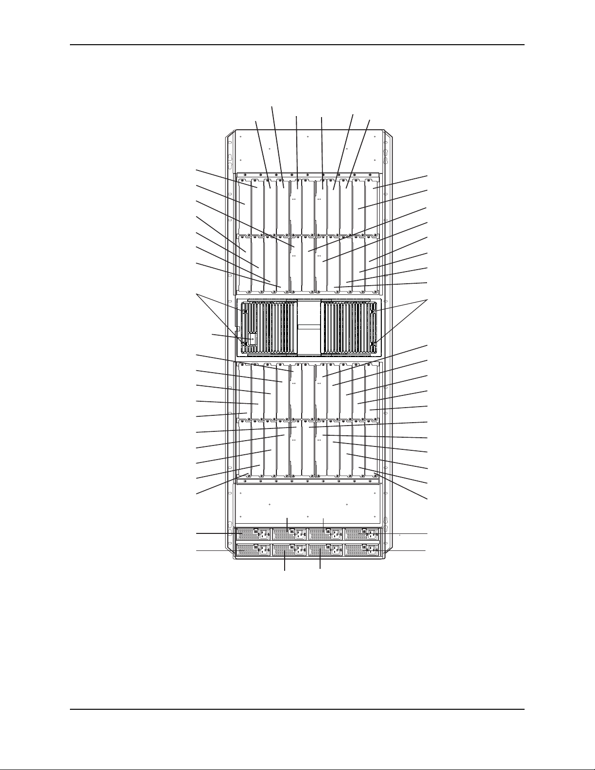
Figure 2.4 NetIron MLX-32 Chassis
Pwr
Active
Pwr
Active
Pwr
Active
Pwr
Active
Pwr
Active
Pwr
Active
Pwr
Active
Pwr
Active
AC OK
DC OK
ALM
AC OK
DC OK
ALM
AC OK
DC OK
ALM
AC OK
DC OK
ALM
AC OK
DC OK
ALM
AC OK
DC OK
ALM
AC OK
DC OK
ALM
AC OK
DC OK
ALM
Switch
Fabric
Slot 1
Switch
Fabric
Slot 3
Interface
Slot 7
Interface
Slot 5
Interface
Slot 9
Interface
Slot 11
Power Supply 2
Power Supply 3
Power Supply 6
Power Supply 7
Interface Slot 3
Interface Slot 1
Switch Fabric Slot 2
Interface Slot 2
Interface Slot 4
Interface Slot 6
Interface Slot 8
ESD St
r
ap Connector
Switch Fabric Slot 5
Interface Slot 23
Interface Slot 21
Interface Slot 19
Interface Slot 17
Switch Fabric Slot 6
Interface Slot 24
Interface Slot 22
Interface Slot 20
Interface Slot 18
Power Supply 1
Power Supply 5
Power Supply 4
Power Supply 8
Interface Slot 15
Interface Slot 13
Management Slot 1
Switch Fabric Slot 4
Interface Slot 16
Interface Slot 14
Interface Slot 12
Interface Slot 10
Switch Fabric Slot 7
Interface Slot 25
Interface Slot 27
Interface Slot 29
Interface Slot 31
Management Slot 2
Switch Fabric Slot 8
Interface Slot 26
Interface Slot 28
Interface Slot 30
Interface Slot 32
Captive Screws
Captive Screws
Product Overview
December 2008 © 2008 Foundry Networks, Inc. 2-5
Page 18

Foundry NetIron MLX Series Installation and Basic Configuration Guide
Upon shipment from the factory, the following components are installed in the four versions of the NetIron MLX
Series chassis as described:
NetIron MLX-4
• Two switch fabric modules.
• A slot blank in each interface module slot. The slot blank covers a slot that does not currently have a module
installed in it, ensuring proper airflow within the chassis.
• A fan tray assembly, which is located in the front right side of the chassis. For more information about the fans,
see “Cooling System” on page 2-23.
• One power supply (AC or DC).
In the slots of the chassis, you can install the following:
• Up to two management modules (one active and one redundant).
• Up to three switch fabric modules.
• Up to four interface modules.
• Up to three power supplies (AC or DC).
Before installing any modules or power supplies, you must remove the slot blank or blank power supply faceplate,
respectively.
NetIron MLX-8
• Two switch fabric modules.
• A slot blank in each interface module slot. The slot blank covers a slot that does not currently have a module
installed in it, ensuring proper airflow within the chassis.
• A fan tray assembly, which is located in the front right side of the chassis. For more information about the fans,
see “Cooling System” on page 2-23.
• Two power supplies (AC or DC).
In the slots of the chassis, you can install the following:
• Up to two management modules (one active and one redundant).
• Up to three switch fabric modules.
• Up to eight interface modules.
• Up to four power supplies (AC or DC).
Before installing any modules or power supplies, you must remove the slot blank or blank power supply faceplate,
respectively.
NetIron MLX-16
• Three switch fabric modules.
• A slot blank in each interface module slot. The slot blank covers a slot that does not currently have a module
installed in it, ensuring proper airflow within the chassis.
• A fan tray assembly located in the front right side of the chassis, and two fan assemblies located at the rear of
the chassis. For more information about the fans, see “Cooling System” on page 2-23.
• Four power supplies (AC or DC).
In the slots of the chassis, you can install the following:
• Up to two management modules (one active and one redundant).
• Up to four switch fabric modules.
• Up to sixteen interface modules.
2-6 © 2008 Foundry Networks, Inc. December 2008
Page 19

Product Overview
• Up to eight power supplies (AC or DC).
NetIron MLX-32
• Empty chassis with backplane and card cage shipping panels, and ten fan assemblies located at the rear of
the chassis, four for the upper card cage, four for the lower card cage, and two for the power supplies.
• Eight switch fabric modules (shipped separately).
• One management module (shipped separately).
• A slot blank for each module slot (shipped separately). The slot blank covers a slot that does not currently
have a module installed in it, ensuring proper airflow within the chassis.
• Four AC power supplies.
In the slots of the chassis, you can install the following:
• Two management modules.
• Eight switch fabric modules.
• Up to 32 interface modules.
• Up to eight AC power supplies.
Before installing any modules or power supplies, you must remove the slot blank or blank power supply faceplate,
respectively (NetIron MLX-4, -8, and 16). On the NetIron MLX-32, before installing any modules, you must remove
the shipping panels covering the upper and lower card cages.
CAUTION: If you do not install a module in a slot, you must keep the slot blank in place. If you run the chassis
with an uncovered slot, the system may overheat.
Figure 2.1, Figure 2.2, Figure 2.3, and Figure 2.4 show the NetIron MLX Series chassis and the slots into which
you install the various modules. You must install the primary power supplies and the redundant power supplies as
described in the figures.
Figure 2.1, Figure 2.2, and Figure 2.3 and Figure 2.4 also show an electrostatic discharge (ESD) connector, into
which you can plug an ESD wrist strap to ground yourself while handling and installing modules.
WARNING: For safety reasons, the ESD wrist strap should contain a 1 meg ohm series resistor.
The NetIron MLX-16 and NetIron MLX-32 chassis versions also include a grounding lug connector, located on the
rear panel (left side).
Management Modules
The following management modules are available for NetIron MLX Series routers:
Part Number Description
NI-MLX-MR NetIron MLX Series management module, 1 GB SDRAM, dual PCMCIA slots,
EIA/TIA-232 and 10/100/1000 Ethernet ports for out-of-band management.
NI-MLX-32-MR NetIron MLX-32 management module, 1 GB SDRAM, dual PCMCIA slots,
EIA/TIA-232 and 10/100/1000 Ethernet ports for out-of-band management
The management module controls the NetIron MLX Series hardware components, runs the networking protocols,
and provides the Real Time Operating System (RTOS).
Each NetIron MLX Series chassis requires one management module and can accept a second one for
redundancy. A redundant management module works along with the active management module. If the active
December 2008 © 2008 Foundry Networks, Inc. 2-7
Page 20
Foundry NetIron MLX Series Installation and Basic Configuration Guide
Pwr
Active
10/100/1000
Port 1
Port 2
Console
module becomes unavailable, the redundant management module automatically takes over the system operation,
minimizing system downtime. For information about the redundancy feature, see the chapter titled "Using a
Redundant Management Module" in the "Foundry NetIron XMR/MLX Configuration Guide".
The NetIron MLX-32 chassis uses a different management module than any of the other Foundry Networks
products. You cannot use management modules designed for the NetIron MLX-32 in any of the other NetIron MLX
Series chassis or management modules in the NetIron MLX-32 chassis designed for the NetIron MLX-4, NetIron
MLX-8, or NetIron MLX-16.
You can install management modules in dedicated slots marked M1 and M2. By default, the system considers the
module installed in the slot marked M1 to be the active management module.
NOTE: The NetIron MLX Series management module is dedicated, which means that you must install it in the
NetIron MLX Series chassis only. If you attempt to install the NetIron MLX Series management module in another
Foundry chassis or a management module intended for another Foundry chassis in the NetIron MLX Series
chassis, the module will not boot up to become active.
Additionally, the NetIron MLX-32 chassis uses a different management module than any of the other NetIron MLX
Series chassis. You cannot use management modules designed for the NetIron MLX-32 in any other Foundry
device, because it will not function properly.
A management module is hot swappable, which allows you to remove and replace it without powering down the
system.
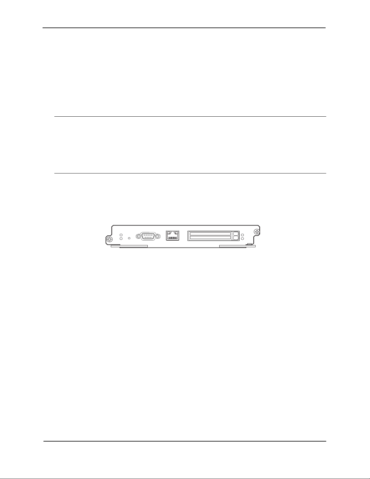
Figure 2.5 shows the management module’s front panel.
Figure 2.5 Management Module Front Panel
The front panel includes the following control features:
• Two PCMCIA slots
• A Console port
• A 10/100/1000 Ethernet port
• Six LEDs
PCMCIA Slots
The PCMCIA slots support a flash PC card. The flash PC card provides storage space in addition to the system’s
flash memory. A flash PC card can store system files, including Boot images, startup configuration files, running
configuration files, and so on. As a result, you can perform system management tasks, such as copying files
between flash PC cards, copying files between a flash PC card and flash memory, and so on.
Console Port
The Console port is a standard DB-9 serial connector through which you can attach a PC or terminal to configure
the NetIron MLX Series system using the CLI.
This port interfaces the control plane only and not the data plane.
10/100/1000 Ethernet Port
The front panel includes a 10BaseT/100BaseTX/1000BaseTX auto-sensing, auto-negotiating Ethernet port. This
port has an RJ-45 unshielded twisted pair (UTP) connector.
Typical uses of this port include but are not limited to the following:
• Connecting a PC through which you can access the system through a Telnet or SSHv2 connection and
2-8 © 2008 Foundry Networks, Inc. December 2008
Page 21

Product Overview
configure, monitor, and manage the NetIron MLX Series system.
• Connecting to the 10BaseT/100BaseTX/1000BaseTX port of a switch or router for connectivity to your
existing management network. You can then access the NetIron MLX Series system and configure, monitor,
and manage the system from a management station.
NOTE: The existing management network into which you can connect the 10/100/1000 Ethernet port must be
separate and isolated from the network over which user packets are switched and routed. For information about
the management port’s functionality, see “Understanding How the Management Port Functions” on page 4-5.
For information about connecting a PC and a switch to the 10/100/1000 Ethernet port, see “Attaching a
Management Station” on page 3-49.
This port interfaces the control plane only and not the data plane.
LEDs
Table 2.1 describes the LEDs on the management module’s front panel.
Table 2.1: Management Module LEDs
LED Position State Meaning
Por t 1
and
Por t 2
Active Lower Left On The module is functioning as the active management
Pwr Upper Left On The module is receiving power.
10/100/1000
Ethernet Port
10/100/1000
Ethernet Port
Each adjacent
to the PCMCIA
slot that it
represents
Above and right
of RJ-45
connector
Above and left
of RJ-45
connector
On or blinking The software is currently accessing the PCMCIA flash card.
Off The software is not currently accessing a PCMCIA flash
card inserted in a slot.
module.
Off The module is functioning as the redundant management
module.
Off The module is not receiving power.
On (Green) A link is established with the remote port.
Off A link is not established with the remote port.
On or blinking
(Yellow)
Off for an
extended period
The port is transmitting and receiving packets.
The port is not transmitting or receiving packets.
December 2008 © 2008 Foundry Networks, Inc. 2-9
Page 22

Foundry NetIron MLX Series Installation and Basic Configuration Guide
Interface Modules
The following interface modules are available for NetIron MLX Series routers:
Part Number Description
NI-MLX-10Gx4 4-port 10 GbE module with IPv4/IPv6/MPLS hardware support--requires XFP
optics
NI-MLX-10Gx2 2-port 10 GbE module with IPv4/IPv6/MPLS hardware support--requires XFP
optics
NI-MLX-1Gx20-SFP 20-port FE/GE (100/1000) module with IPv4/IPv6/MPLS hardware support--
requires SFP optics
NI-MLX-1Gx20-GC 20-port 10/100/1000 copper modules with IPv4/IPv6/MPLS hardware support
NI-X-OC192x2 2-port Packet over SONET (SDH) OC-192 (STM-64) interface module
NI-X-OC192x1 1-port Packet over SONET (SDH) OC-192 (STM-64) interface module
NI-X-OC48x8 8-port Packet over SONET (SDH) OC12/48 (STM-4/16) interface module
NI-X-OC48x4 4-port Packet over SONET (SDH) OC-12/48 (STM-4/16) interface module
NI-X-OC 48x2 2-port Packet over SONET (SDH) OC-12/48 (STM-4/16) interface module
Depending on the size of you NetIron MLX Series chassis, you can install up to 32 NetIron MLX Series interface
modules as described:
• NetIron MLX-4: Supports up to 4 interface modules
• NetIron MLX-8: Supports up to 8 interface modules
• NetIron MLX-16: Supports up to 16 interface modules
• NetIron MLX-32: Supports up to 32 interface modules
NOTE: A NetIron MLX Series interface module is dedicated, which means that you must install it in the NetIron
MLX Series chassis only. If you attempt to install a NetIron MLX Series interface module in another Foundry
chassis or an interface module intended for another Foundry chassis in the NetIron MLX Series chassis, the
module will not boot up to become active. Interface modules can be shared between NetIron MLX-4, NetIron MLX8, NetIron MLX-16, and NetIron MLX-32.
The interface modules are hot swappable, which means you can remove and replace them without powering down
the system.
10 Gigabit Ethernet Interface Modules (2-port and 4-port)
Figure 2.6 shows the 2-port and 4-port 10 Gigabit Ethernet module’s front panels with XFP optics installed.
2-10 © 2008 Foundry Networks, Inc. December 2008
Page 23
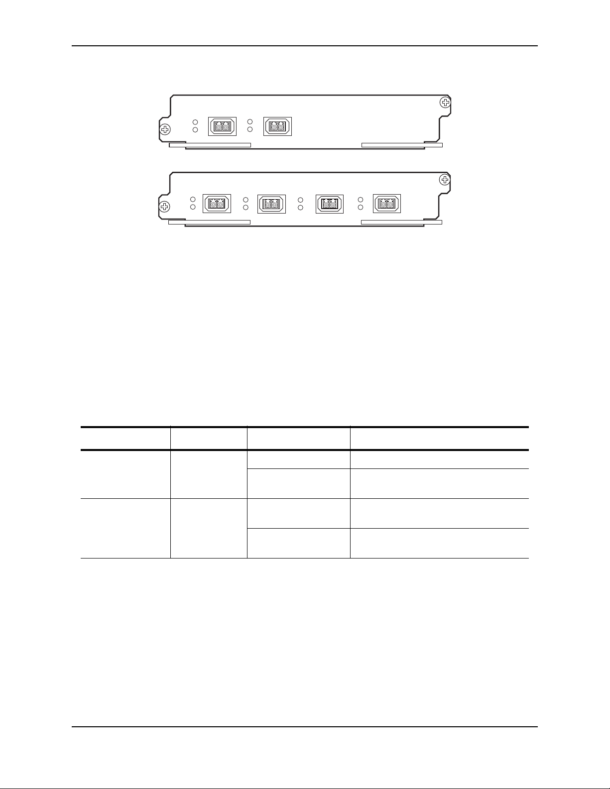
Figure 2.6 2- port and 4-port 10 Gigabit Ethernet Modules Front Panel
Lnk
Act
Lnk
Act
Lnk
Act
Lnk
Act
1
2
34
Lnk
Act
Lnk
Act
1
2
The front panel of the 4-port module includes the following control features:
• Eight LEDs
• Four 10 Gigabit Ethernet XFP optics slots
The front panel of the 2-port module includes the following control features:
• Four LEDs
• Two 10 Gigabit Ethernet XFP optics slots
LEDs
The module’s front panel includes two LEDs that indicate the status of each port.
Product Overview
Table 2.2 describes the LEDs on the 10 Gigabit Ethernet module’s front panel.
Table 2.2: 10 Gigabit Ethernet Module LEDs
LED Position State Meaning
Link Left of each
Ethernet port
On A link is established with the remote port.
Off A link is not established with the remote
port.
Active Left of each
Ethernet port
On The port is transmitting and receiving
packets.
Off The port is not transmitting or receiving
packets.
10 Gigabit Ethernet Ports
A 10 Gigabit Ethernet module contains two or four physical ports, through which you can connect your NetIron
MLX Series router to other network devices at a speed of 10 Gigabits.
Into a physical port, you must insert a fiber-optic transceiver provided by Foundry. The XFP-compliant fiber-optic
modules provide an optical transceiver or physical medium-dependent (PMD) interface for single or multi-mode
fiber that can be used with the LAN physical layer (PHY).
December 2008 © 2008 Foundry Networks, Inc. 2-11
Page 24
Foundry NetIron MLX Series Installation and Basic Configuration Guide
Port Status LEDs
(In each pair, the left most LED supports the port in the top row directly above it
and the right-most LED supports the port in the bottom directly above it )
The following 10 Gigabit optics are available from Foundry:
Table 2.3: XFP-Compliant Optics for the 10 GbE Ethernet Interface Module
Part Number Description
10G-XFP-SR 850nm serial pluggable XFP optic (LC), target range 300m over multi-mode fiber
10G-XFP-LR 1310nm serial pluggable XFP optic (LC) for up to 10km over single-mode fiber
10G-XFP-ER 1550nm serial pluggable XFP optic (LC) for up to 40km over single-mode fiber
10G-XFP-ZR 1550nm serial pluggable XFP optic (LC) for up to 80km over single-mode fiber
10G-XFP-ZRD-XXXX-AA 10GBase-ZR DWDM, XFP optic, 80km, 1530.33 to 1561.42
10G-XFP-CX4 10-Base-CX4, XFP transceiver, 15km, CX connector (supported only on integrated
XFP slot on FGS624XGP and FGS624XGP-POE)
For more information about the fiber-optic transceivers and the cabling associated with them, see “Installing a
Fiber-Optic Module” on page 4-5.
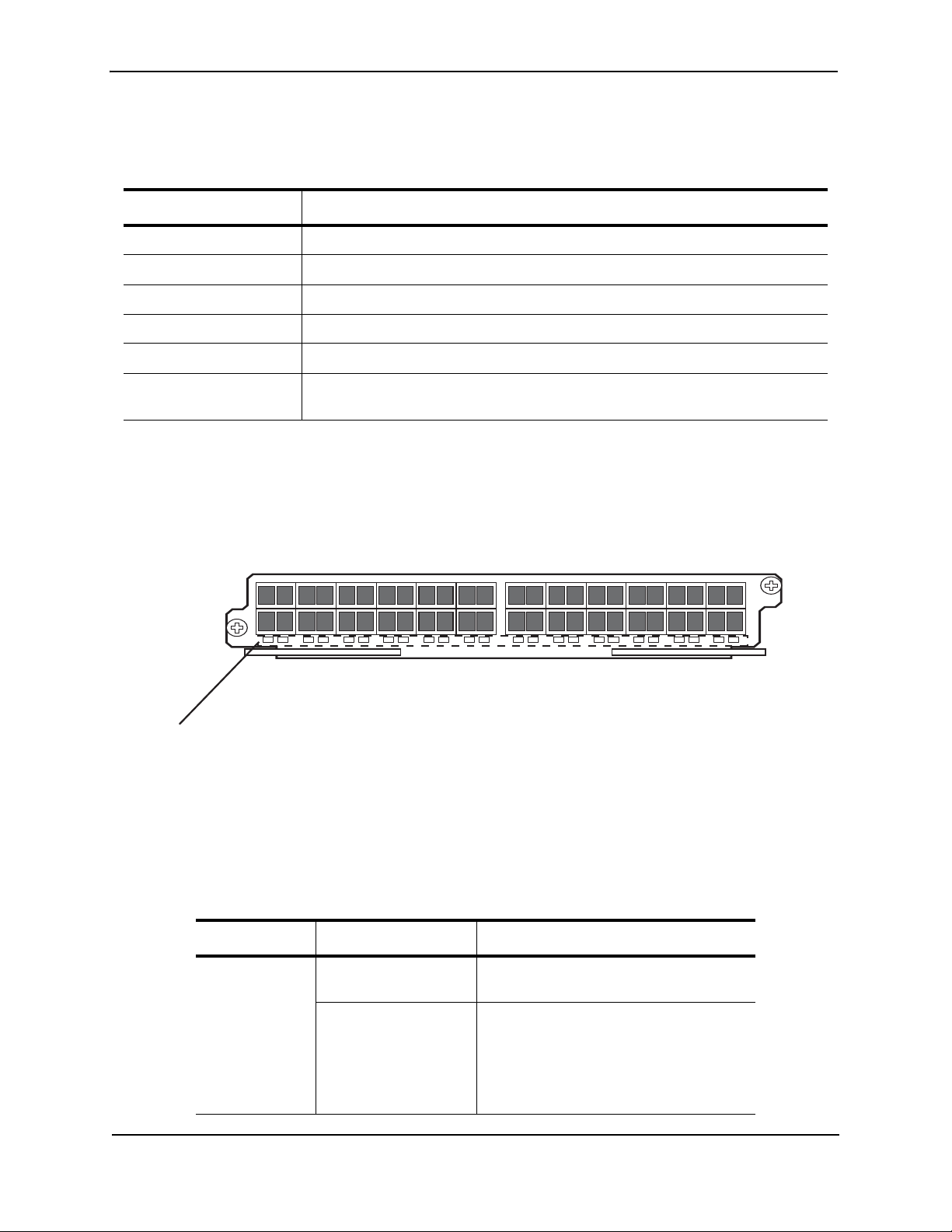
FE/GbE (100/1000) Ethernet Interface Module (SFP)
Figure 2.8 shows the 20-port 100/1000 Ethernet mini-GBIC (or SFP) module’s front panel.
Figure 2.7 20-port 100/1000 Ethernet SFP Module Front Panel
The front panel includes the following control features:
• LEDs - The LEDs to the left support the top
• 20 100/1000 Ethernet mini-GBIC (SFP) ports
Table 2.4: Gigabit Ethernet Module LEDs
Position State Meaning
Below each
On or blinking The port is transmitting and receiving
Ethernet port
(Left-side LED
supports port in
Off for an extended
period
top row while
right-side LED
supports port in
bottom row)
2-12 © 2008 Foundry Networks, Inc. December 2008
packets.
The port is not transmitting or receiving
packets.
Page 25

Product Overview
100/1000 Ethernet Ports
This Ethernet interface module contains 20 physical ports, through which you can connect your NetIron MLX
Series router to other network devices at a speed of 100 Mbps or 1 GbE.
Into a physical port, you must insert a fiber-optic transceiver provided by Foundry. The SFP-compliant fiber-optic
modules provide an optical transceiver or physical medium-dependent (PMD) interface for fiber that can be used
with the LAN physical layer (PHY)
The following 100 Mbps and 1 GbE optical transceivers are available from Foundry:
Table 2.5: SFP-Compliant Transceivers for the 100/1000 Ethernet Interface Module
Part Number Description
E1MG-TX SFP Copper, RJ-45 connector
E1MG-SX 1000Base-SX SFP optic, multi-mode fiber, LC connector
E1MTG-SX 1000Base-SX SFP optic, multi-mode fiber, MTRJ connector
E1MG-SX2-1310 1310 1000Base-SX SFP optic multi-mode fiber, LC connector and support for
distances up to 2km
E1MG-LX 1000Base-LX SFP optic, single-mode fiber, LC connector
E1MG-LHA 1000Base-LHA SFP optic, single-mode fiber, LC connector
E1MG-LHB 1000Base-LHB SFP optic, single-mode fiber, LC connector, 150km Maximum
Reach
E1MG-BXU 1000Base-BXU SFP optic single-mode fiber, 1310nm, LC connector.
This optic can only be connected to an E1MG-BXD
E1MG-BXD 1000Base-BXD SFP optic single-mode fiber, 1490nm, LC connector.
This optic can only be connected to an E1MG-BXU
E1MG-CWDM80-1470 CWDM SFP optic, 80km, 1470nm, LC connector
E1MG-CWDM80-1490 CWDM SFP optic, 80Km, 1490nm, LC connector
E1MG-CWDM80-1510 CWDM SFP optic, 80Km, 1510nm, LC connector
E1MG-CWDM80-1530 CWDM SFP optic, 80Km, 1530nm, LC connector
E1MG-CWDM80-1550 CWDM SFP optic, 80Km, 1550nm, LC connector
E1MG-CWDM80-1570 CWDM SFP optic, 80Km, 1570nm, LC connector
E1MG-CWDM80-1590 CWDM SFP optic, 80Km, 1590nm, LC connector
E1MG-CWDM80-1610 CWDM SFP optic, 80Km, 1610nm, LC connector
E1MG-100FX 100Base-FX SFP optic multi-mode fiber, LC connector
E1MG-100BXU 100Base-BXU SFP optic single-mode fiber, 1310nm, LC connector.
This optic can only be connected to an E1MG-100BXD.
E1MG-100BXD 100Base-BXD SFP optic single-mode fiber, 1490nm, LC connector.
This optic can only be connected to an E1MG-100BXU.
E1MG-100FX-IR 100BaseFX-IR optic for SMF with LC connector. For distances up to 15nm.
E1MG-100FX-LR 100BaseFX-LR SFP optic for SMF with LC connector. For distances up to 40km.
December 2008 © 2008 Foundry Networks, Inc. 2-13
Page 26
Foundry NetIron MLX Series Installation and Basic Configuration Guide
10/100/1000 Ethernet Interface Module (RJ-45)
Figure 2.8 shows the 20-port 10/100/1000 Ethernet module’s front panel.
Figure 2.8 20-port 10/100/1000 Copper Ethernet Module Front Panel
The front panel includes the following control features:
•LEDs
• Twenty 10/100/1000 Copper Ethernet ports
Table 2.6: Gigabit Ethernet Module LEDs
LED Position State Meaning
Link/Active As shown in
Figure 2.8 on
page 2-14.
On (solid) A link is established with the remote port
(with no traffic).
Blinking The port is transmitting and receiving
packets.
Off A link is not established with the remote
port and no traffic is being passed.
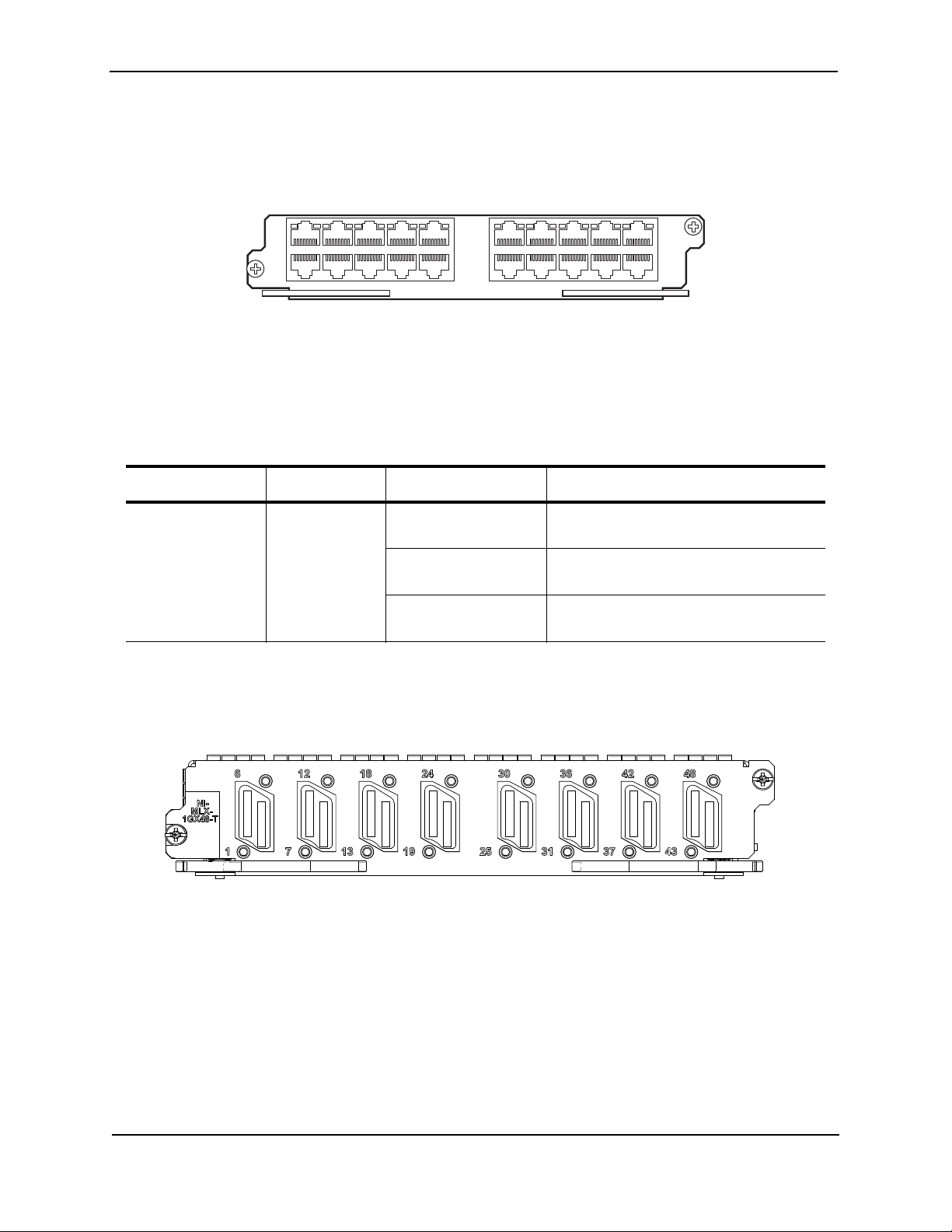
1 Gigabit x 48-T Module
Figure shows the 1 Gigabit x 48-T module’s front panel.
Figure 2.91 Gigabit x 48-T Module Front Panel
The front panel includes the following control features:
•LEDs
• 8 ports of Mini-RJ21 connectors with each connector supporting 6 ports of 1GbE
The front panel includes eight Mini RJ-21 connectors that support six 1 Gigabit Ethernet ports each. A cable
connects from the RJ-21 connector on the interface module to a Mini RJ-21 connector on a patch panel. At the
patch panel, the ports are broken out into individual RJ-45 connectors for each port.
Cables and patch panels that support this module are available through any Tyco International distribution partner.
Information about these products is available at the following URL:
www.ampnetconnect.com/foundrynetworks
2-14 © 2008 Foundry Networks, Inc. December 2008
Page 27

Table 2.7: Mini RJ-45 Module LEDs
LED Position State Meaning
Product Overview
Link/Active As shown in
Figure on
page 2-14.
On (solid) A link is established with the remote port
(with no traffic).
Blinking The port is transmitting and receiving
packets.
Off A link is not established with the remote
port and no traffic is being passed.
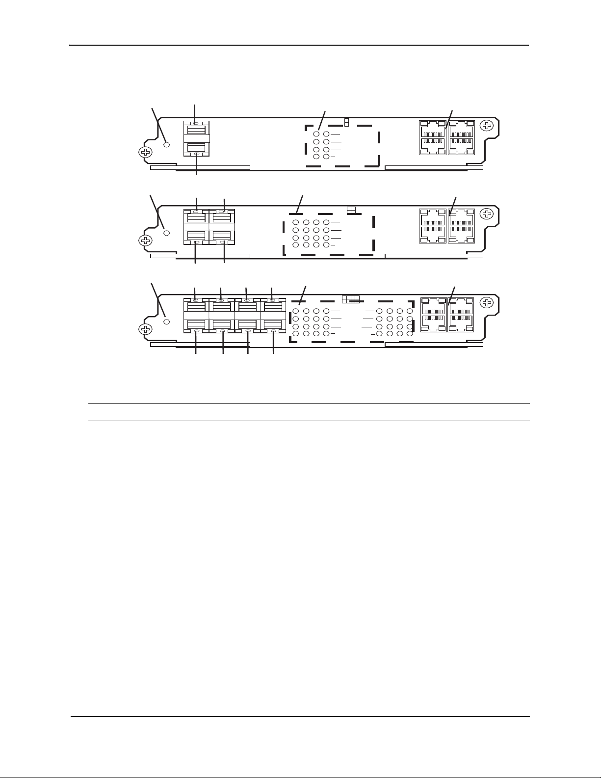
POS Interface Modules
The NetIron MLX routers support the following Packet Over SONET/SDH (POS) interface modules beginning with
release 03.4.00 of Multi-Service IronWare software:
• Dual speed (OC-48c/STM-16)/(OC-12c/STM-4) – Available with 2, 4, or 8 ports
• Single speed OC-192C/STM-64 – – Available with 1 or 2 ports
Dual Speed OC-12c and OC-48c
The dual-speed OC-48c/OC-12c POS module is reconfigurable and can be reconfigured through CLI to support
OC-48 or OC-12 speeds.
NOTE: All POS modules for the NetIron MLX Series support both Packet over Socket and Packet over SDH
Figure 2.10 highlights the following features of the OC-12c/OC-48c POS interface module front panels:
• 2, 4, or 8 ports that can accommodate SFP optics for the OC-12c/OC-48c modules
• A single LED to indicate if power is being received by the module
• 4 LEDs per port that indicate the following port status: Active/Local Rail, TX Pkt, RX Pkt, and Carrier Rcvd /
Remote Fail
• 2 IN and 2 OUT RJ-48 connectors to provide an BITS external clock source and to propagate a common
clock source (Line or BITS) among POS modules
December 2008 © 2008 Foundry Networks, Inc. 2-15
Page 28
Foundry NetIron MLX Series Installation and Basic Configuration Guide
Power
Active /
Local Fail
Tx Pk
t
BITS1
BITS2
Rx Pkt
Carrier Rcvd /
Remote Fail
I
N
O
U
T
1234 5678
1234567
8
I
N
O
U
T
Power
Active /
Local Fail
Tx Pk
t
BITS1
BITS2
Rx Pkt
Carrier Rcvd /
Remote Fail
I
N
O
U
T
1234
123
4
I
N
O
U
T
Power
Active /
Local Fail
Tx Pk
t
BITS1
BITS2
Rx Pkt
Carrier Rcvd /
Remote Fail
I
N
O
U
T
1
2
1
2
I
N
O
U
T
Port 1
Port 2
Port 1
Port 3
Port 2 Port 4
Port 1 Port 3 Port 5 Port 7
Port 2 Port 4 Port 6 Port 8
Port Status LEDs
Port Status LEDs
Port Status LEDs BITS Clocking Ports
BITS Clocking Ports
BITS Clocking Ports
Power
Power
Power
Figure 2.10 OC-12c/OC-48c POS Interface Modules
Single-Speed OC-192c
NOTE: All POS modules for the NetIron MLX Series support both Packet over Socket and Packet over SDH
Figure 2.11 highlights the following features of the OC-192c POS interface module front panel:
• 1 or 2 ports that accommodate XFP optics
• A single LED to indicate if power is being received by the module
• 4 LEDs per port that indicate the following port status: Active/Local Rail, TX Pkt, RX Pkt, and Carrier Rcvd /
Remote Fail
• 2 IN and 2 OUT RJ-48C connectors to provide an BITS external clock source and to propagate a common
clock source (Line or BITS) among POS modules
2-16 © 2008 Foundry Networks, Inc. December 2008
Page 29
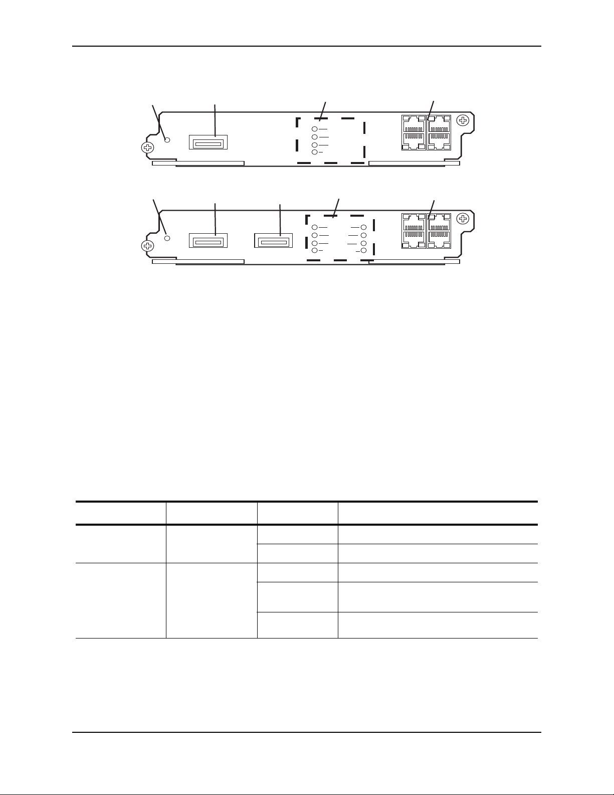
Figure 2.11 OC-192c POS Interface Modules
Power
Active /
Local Fail
Tx Pk
t
BITS1
BITS2
Rx Pkt
Carrier Rcvd /
Remote Fail
I
N
O
U
T
12
I
N
O
U
T
1
2
Power
Active /
Local Fail
Tx Pk
t
BITS1
BITS2
Rx Pkt
Carrier Rcvd /
Remote Fail
I
N
O
U
T
1
I
N
O
U
T
1
Power
Power
Port 1
Port 2
Port 1
Port Status LEDs
Port Status LEDs
BITS Clocking Ports
BITS Clocking Ports
The front panels of the POS interface modules contain the following:
• a power LED
• 2, 4, or 8 ports that can accommodate SFP optics for the OC-12c and OC-48c modules
Product Overview
• 1 or 2 ports that accommodate XFP for the OC-192c transceivers
• A single LED to indicate if power is being received by the module
• 4 LEDs per port that indicate port status
• 2 IN and 2 OUT RJ-48C connectors to provide an BITS external clock source and to propagate a common
clock source (Line or BITS) among POS modules
LED Operation
The front panels of the NetIron XMR/MLX POS interface modules contain a single Power LED for the entire
module and 4 LEDs per port to indicate port status as shown in Figure 2.10 and Figure 2.11, and described in
Table 2.8.
Table 2.8: POS Module LEDs
LED Position State Meaning
Power Far left of module On Power is being received by the module
Off The module is not receiving power.
Active/Local Failure center of board:
• top position
One LED per-port
as defined by
column position
Green Port is enabled.
Red Port is enabled and their is a locally detected
error condition.
Off Port is disabled.
December 2008 © 2008 Foundry Networks, Inc. 2-17
Page 30
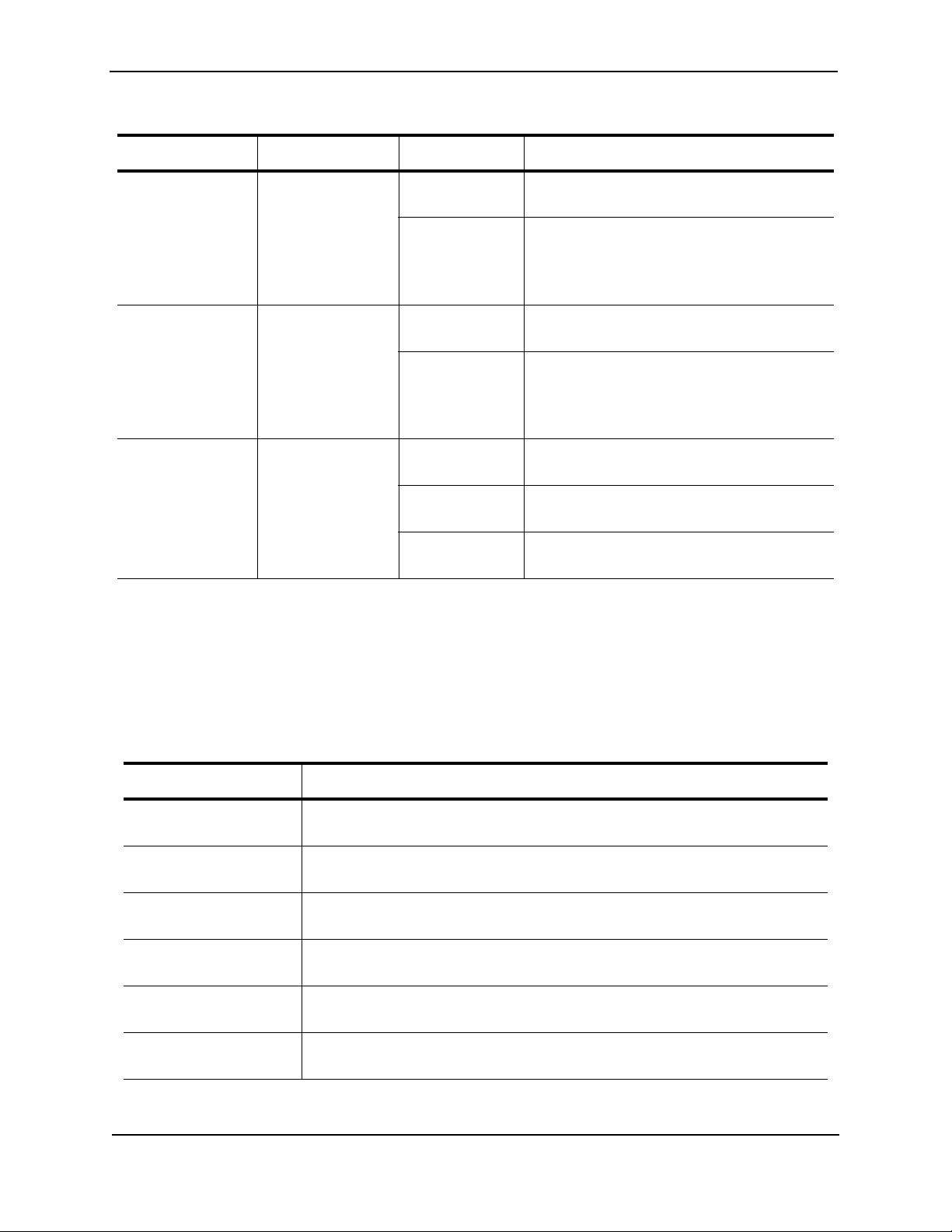
Foundry NetIron MLX Series Installation and Basic Configuration Guide
Table 2.8: POS Module LEDs (Continued)
LED Position State Meaning
TX Pkt center of board:
• 2nd from top
position
One LED per-port
as defined by
column position
Rx Pkt center of board:
• 3rd from top
position
One LED per-port
as defined by
column position
Carrier Received /
Remote Failure
center of board:
• 4th from top
position
One LED per-port
as defined by
column position
Blinking Green Blinks during transmission of packets from the
specified port.
Off No packets are being transmitted from the
specified port.
Blinking Green Blinks during reception of packets on the
specified port.
Off
Green Laser signal is being received at the specified
port.
Yellow Laser signal is being received at the specified
port with an alarm.
Off Laser signal is not being received at the
specified port.
OC-12c and OC-48c Ports
The OC-12c/OC-48c POS interface modules support 2, 4, or 8 ports. Into a physical port, you must insert an
optical transceiver provided by Foundry.
The following SFP optical transceivers are available from Foundry for use with the The OC-12c /OC-48c POS
interface modules:
Table 2.9: SFP-Compliant Optics for the OC-12c and OC-48c POS Interface Modules
Part Number Description
OC12-SFP-MM Supports POS OC-12 up to 500 m over multi-mode fiber (MMF), Hot-pluggable,
Duplex LC Connector.
OC12-SFP-IR1 Supports POS OC-12 SR1/IR1 up to 15 km over single-mode fiber (SMF), Hot-
pluggable, Duplex LC Connector. No attenuator need for SR-1 applications.
OC12-SFP-LR1 Supports POS OC-12 LR-1 up to 40 km over single-mode fiber (SMF), Hot-
pluggable, Duplex LC Connector.
OC12-SFP-LR2 Supports POS OC-12 LR-2 up to 80 km over single-mode fiber (SMF), Hot-
pluggable, Duplex LC Connector.
OC48-SFP-SR1 Supports POS OC-48 SR-1 up to 2 km over single-mode fiber (SMF), Hot-
pluggable, Duplex LC Connector.
OC48-SFP-IR1 Supports POS OC-48 IR-1 up to 15 km over single-mode fiber (SMF), Hot-
pluggable, Duplex LC Connector.
2-18 © 2008 Foundry Networks, Inc. December 2008
Page 31

Product Overview
Table 2.9: SFP-Compliant Optics for the OC-12c and OC-48c POS Interface Modules (Continued)
Part Number Description
OC48-SFP-LR1 Supports POS OC-48 LR-1 up to 40 km over single-mode fiber (SMF), Hot-
pluggable, Duplex LC Connector.
OC48-SFP-LR2 Supports POS OC-48 LR-2 up to 80 km over single-mode fiber (SMF), Hot-
pluggable, Duplex LC Connector.
OC-192c Ports
The OC-192c POS interface modules support 1 or 2 ports. Into a physical port, you must insert an optical
transceiver provided by Foundry.
The following XFP optical transceivers are available from Foundry for use with the OC-192c POS interface
modules:
Clocking and Timing a POS Interface Module
Table 2.10: XFP-Compliant Optics for the OC-192 POS Interface Modules
Part Number Description
OC192-XFP-SR1 Supports POS OC-192 SR-1 up to 2 km over single mode fiber (SMF), Hot-
pluggable, Duplex LC Connector
OC192-XFP-IR2 Supports POS OC-192 IR-2 up to 40 km over single mode fiber (SMF), Hot-
pluggable, Duplex LC Connector
OC192-XFP-LR2 Supports POS OC-192 up to 80 km over single mode fiber (SMF), Hot-pluggable,
Duplex LC Connector
The POS Interface Modules support the following timing configurations:
• Internal Timing – This option uses the internal statum 3 clock. This is the default clocking configuration.
• Loop TIming – This option receives timing from the line
• Line Timing – This interface receives timing from the line and is used to clock all ports on the same interface
module but not for the entire chassis.
• External (BITS) Timing – This option allows timing to be provided by a central office BITS system. Each POS
interface module has 4 RJ-48C ports for connection to the external BITS system. The two input ports (labeled
IN) are for receiving clocking. The two output ports (labeled OUT) provide clocking to another POS Interface
module.
Configuration of the internal and external clocking and timing options are described in the chapter titled "Using
Packet Over SONET Modules" in the Foundry NetIron XMR/MLX Configuration Guide.
Clocking Port Pin Assignments
The Clocking ports are standard RJ-48C connectors. The BITS IN and BITS OUT connectors are configured
differently as described in the following tables:
December 2008 © 2008 Foundry Networks, Inc. 2-19
Page 32

Foundry NetIron MLX Series Installation and Basic Configuration Guide
Table 2.11 describes pin assignments for the BITS IN connectors and Table 2.12 describes pin assignments for
the BITS OUT connectors.
Table 2.11: BITS IN Port Pin Assignments
Pin Number MDI-X Ports
1 RX Ring
2RX Tip
3 Not used
4 Not used
5 Not used
6 Not used
7 Not used
8 Not used
Table 2.12: BITS OUT Port Pin Assignments
Pin Number MDI-X Ports
1 Not used
2 Not used
3 Not used
4 TX Ring
5TX Tip
6 Not used
7 Not used
8 Not used
WARNING: The ports labeled BITS1, BITS2 are safety extra low voltage (SELV) circuits. SELV circuits should
only be connected to other SELV circuits. All interconnected equipment is in the same building as the unit.
Switch Fabric Module
The following switch fabric modules are available for NetIron MLX Series routers:
Part Number Description
NI-X-SF1 NetIron MLX/XMR 4-slot system switch fabric module
NI-X-SF3 NetIron MLX/XMR 8/16-slot system switch fabric module
2-20 © 2008 Foundry Networks, Inc. December 2008
Page 33

Product Overview
Active
Pwr
NI-SWF
Part Number Description
NI-X-32-SF NetIron MLX/XMR 32-slot system switch fabric module
The switch fabric module switches user packets from one interface module installed in a chassis to another. The
NetIron MLX Series routers can be configured with switch fabric modules as described:
• NetIron MLX-4: Accommodates three switch fabric modules with two required and one redundant for a fullyloaded system. It is shipped with two switch fabric modules. You must purchase an additional switch fabric
module if you want your NetIron MLX-4 equipped for redundancy.
• NetIron MLX-8: Accommodates three switch fabric modules with two required and one redundant for a fullyloaded system. It is shipped with two switch fabric modules. You must purchase an additional switch fabric
module if you want your NetIron MLX-8 equipped for redundancy.
• NetIron MLX-16: Accommodates four switch fabric modules with three required and one redundant for a fullyloaded system. It is shipped with three switch fabric modules. You must purchase an additional switch fabric
module if you want your NetIron MLX-16 equipped for redundancy.
• NetIron MLX-32: Accommodates and is shipped with eight switch fabric modules.
NOTE: The switch fabric modules used for the NetIron MLX-4 are a different part than those used on the NetIron
MLX-8, NetIron MLX-16, and NetIron MLX-32.
Also, the switch fabric modules used for the NetIron MLX-32 are different than those used on the NetIron MLX-4,
NetIron MLX-8, and NetIron MLX-16.
NOTE: The NetIron MLX Series switch fabric module is dedicated, which means that it functions properly in the
NetIron MLX Series chassis only. If you attempt to install a NetIron MLX Series router fabric module in another
Foundry chassis or a switch fabric module intended for another Foundry chassis in the NetIron MLX Series
chassis, the chassis and switch fabric module will not function properly.
Figure 2.12 shows the switch fabric module’s front panel.
Figure 2.12 Switch Fabric Module Front Panel
The front panel includes two LEDs, which Table 2.13 describes.
Table 2.13: Switch Fabric Module LEDs
LED Position State Meaning
Pwr Above Active
LED
On The module is receiving power.
Off The module is not receiving power.
Active Below Pwr LED On The chassis switch fabric is active and
ready to switch user packets.
Off for an extended
period
The chassis switch fabric is not active and
cannot switch user packets.
December 2008 © 2008 Foundry Networks, Inc. 2-21
Page 34

Foundry NetIron MLX Series Installation and Basic Configuration Guide
Power Supplies
The NetIron MLX Series routers support the following power supply options:
• NetIron MLX-4: Accommodates three power supplies (AC or DC) with one required and two redundant. It is
shipped with one power supply. You must purchase one or two additional power supplies if you want your
NetIron MLX-4 equipped for redundancy.
• NetIron MLX-8: Accommodates four power supplies (AC or DC) with two required and two redundant.
Because power is supplied over a common power bus, any power supply purchased in addition to the two
required will provide backup for any supply that fails. Equipping a NetIron MLX-8 with two additional power
supplies provides full redundancy for both of the required power supplies.
• NetIron MLX-16: Accommodates eight power supplies (AC or DC) with four required and four redundant.
Because power is supplied over a common power bus, any power supply purchased in addition to the four
required will provide backup for any supply that fails. Equipping a NetIron MLX-16 with four additional power
supplies provides full redundancy for all of the required power supplies.
• NetIron MLX-32: Accommodates eight power supplies. Power supplies available include: 2100W AC, 2400W
AC, and 2400W DC. The redundancy configuration is as follows:
• If 2100W AC power supplies are used, then five are required and three are redundant. This is for 200-240
volts AC only.
• If 2400W AC or 2400W DC are used, then four are required and four are redundant. This is for 200-240
volts AC only.
• If 2100W and 2400W power supplies (AC or DC) are used in combination, then five are required and
three are redundant.
Because power is supplied over a common power bus, any power supply purchased in addition to the four or
five required provides backup for any supply that fails.
NOTE: The 2400W AC and DC power supplies for the NetIron MLX-32 are new parts and will be released
shortly. Please check with Foundry Networks for availability of these parts.
NOTE: Only the NetIron MLX-8 and the NetIron MLX-16 power supplies are interchangeable with each other.
The NetIron MLX-4 and NetIron MLX-32 power supplies are not interchangeable with any other chassis.
For power supply specifications, see “Power Specifications” on page 8-1.
In the NetIron MLX-8, NetIron MLX-16 and NetIron MLX-32, you install the power supplies (AC or DC) in the slots
along the bottom of the chassis. In the NetIron MLX-4, the power supplies (AC or DC) are installed in slots in the
rear of the chassis. The installed power supplies provide power to all chassis components, sharing the workload
equally and reporting their status to the management module. If the management module detects that one of
these power supplies has failed or overheated, the management module will redistribute the failed power supply’s
workload to the remaining power supplies.
Each power supply has three LEDs on its faceplate that provide status for the input power, output power and
notification of alarms sent. If the input power and output power LEDs are on (a steady green), the power supply is
providing power to the chassis components. For more information about operation of the power supply LEDs, see
the AC and DC power supply sections in Table 3.5 on page 3-51. The power supplies are hot swappable, which
means you can remove and replace them without powering down the system. For information about replacing a
power supply, see “Replacing a Power Supply” on page 6-10.
NOTE: After a power supply is removed from a NetIron MLX Series chassis, the software determines if there is
enough power to power-on the interface modules. If it determines that there isn’t enough power, some interface
modules will be powered off.
WARNING: The power supplies are hot swappable, which means they can be removed and replaced while the
NetIron MLX Series chassis is powered on and running. However, Foundry recommends that you disconnect a
power supply from its power source before removing and replacing the supply. The NetIron MLX-4, -8, or -16 chas-
2-22 © 2008 Foundry Networks, Inc. December 2008
Page 35

Product Overview
Fan Module
NetIron MLX 4
sis can be running while a power supply is being removed and replaced, but the power supply itself should not be
connected to a power source. Otherwise, you could be injured or the power supply or other parts of the device
could be damaged. (In the NetIron MLX-32 chassis, you cannot unlatch and remove a power supply without first
releasing the cord retainer and removing the power cord.)
Built-in Mounting Brackets
The NetIron MLX-4 and NetIron MLX-8 chassis has built-in mounting brackets that enable you to front-mount the
chassis in a standard 19-inch (EIA310-D) rack. For instructions about using the built-in mounting brackets to
mount the device in a rack, see “Installing a NetIron MLX Series Router”.
Alternatively, you can use a mid-mount kit (ordered separately) to center-mount the NetIron MLX chassis using
two L-shaped mounting brackets. The mid-mount kit comes with instructions for installing the mounting brackets
and mounting the device in a rack.
Contact Foundry Networks for information about mid-mount kits.
Cooling System
The cooling system of the NetIron MLX Series is configured as described:
• NetIron MLX-4: Is equipped with a fan module containing two 4-speed fans and two fan controllers to support
redundancy.
• NetIron MLX-8: Is equipped with a fan module containing four 4-speed fans and four fan controllers to support
redundancy.
• NetIron MLX-16: Is equipped with three fan assemblies. The fan tray located in the lower front of the chassis
contains six 4-speed fans. There are two fan assemblies located in the rear of the chassis. Each of these
contain a 4-speed fan that pulls air through the chassis. The NetIron MLX-16 is equipped with eight fan
controllers to support redundancy.
• NetIron MLX-32: Is equipped with ten fan assemblies in the rear of the chassis. Each of these contains a 4speed fan that pulls air through the chassis. The fan trays support four settings, 50%, 75%, 88%, and 100%,
as the normal fan speeds, and the management module sets all system fans to one of these speeds.
As shown in Figure 2.13 and Figure 2.14, the fans are located in the front of the NetIron MLX-4 and NetIron MLX8 chassis. Figure 2.15 and Figure 2.16 show the front and rear locations of the fans on the NetIron MLX-16. Figure
2.17 shows the locations of all 10 fans at the rear of the NetIron MLX-32 chassis.
Figure 2.13 Fan Component Locations for the NetIron MLX-4
December 2008 © 2008 Foundry Networks, Inc. 2-23
Page 36

Foundry NetIron MLX Series Installation and Basic Configuration Guide
NetIron MLX 8
Fan Module
Front
Fan Assembly
Figure 2.14 Fan Component Locations for the NetIron MLX-8
Figure 2.15 Front Fan Component Locations for the NetIron MLX-16
2-24 © 2008 Foundry Networks, Inc. December 2008
Page 37

Figure 2.16 Rear Fan Component Locations for the NetIron MLX-16
Fan Modules
Product Overview
December 2008 © 2008 Foundry Networks, Inc. 2-25
Page 38

Foundry NetIron MLX Series Installation and Basic Configuration Guide
Fan Module 1
Fan Module 2
Fan Module 6
Fan Module 8
Fan Module 10
Fan Module 4
Fan Module 3
Fan Module 5
Fan Module 7
Fan Module 9
Figure 2.17 Rear Fan Component Locations for the NetIron MLX-32
Upon system startup, the fans in the NetIron MLX Series router operate at high speed, then the management
module lowers the fan speed to low speed.
By default, the NetIron MLX Series router polls the temperature sensor on each module every 60 seconds to get a
temperature reading. Depending on the temperature readings for the modules, the system can do the following:
• Leave the fan speed as is
• Increase the fan speed
• Decrease the fan speed
• Shut down a module to prevent damage
If the temperature of a module exceeds specified high temperature thresholds, the system generates a Syslog
message and SNMP trap. The system can also shut the module down if the temperature exceeds the highest
threshold.
You can change default low and high temperature thresholds for modules and fan speeds.
2-26 © 2008 Foundry Networks, Inc. December 2008
Page 39

Product Overview
The NetIron MLX-32 fan control modules include a bi-color LED, which indicates the status of the fans. Table 2.14
describes the LED.
Table 2.14: NetIron MLX-32 Fan Control Module LED
LED Position State Meaning
Fan control module
LED
The NetIron MLX Series chassis ships with all fan components fully installed. However, Foundry recommends that
you replace the air filters quarterly. For information about replacing the air filter and if necessary, other fan
components, see “Maintaining a NetIron MLX Series Router” on page 6-1. The fan components are hot
swappable, which means you can remove and replace them without powering down the system.
CAUTION: To avoid overheating of the NetIron MLX Series chassis, remove only one fan at a time. Failure to
have sufficient air flow within the chassis for an extended period of time may cause damage to the system. Do not
remove all fans from the chassis at one time.
Rear of chassis Off The fans are not receiving power.
Green The fans are working and responding to
controls from the fan control module.
Red The fans are not working and not responding
to controls from the fan control module.
Rack Mount Kit
The NetIron MLX Series chassis are shipped equipped for mounting in a standard 19-inch (EIA310-D) rack as
described:
• The NetIron MLX-4 and NetIron MLX-8 are equipped with built-in mounting brackets.
• The NetIron MLX-16 and NetIron MLX-32 chassis ship with two L-shaped mounting brackets.
NOTE: You must supply your own standard #12-24 pan-head screws for attaching the mounting brackets to your
rack.
In a rack, you can install the following number of NetIron MLX Series chassis depending on the model:
• NetIron MLX-32 – 1 NetIron MLX-32 chassis
• NetIron MLX-16 – up to 3 NetIron MLX-16 chassis
• NetIron MLX-8 – up to 6 NetIron MLX-8 chassis
• NetIron MLX-4 – up to 10 NetIron MLX-4 chassis
Supported Software Features
For a complete list of software features supported on the NetIron MLX Series router, see the software release
notes for this device.
December 2008 © 2008 Foundry Networks, Inc. 2-27
Page 40

Foundry NetIron MLX Series Installation and Basic Configuration Guide
2-28 © 2008 Foundry Networks, Inc. December 2008
Page 41

Chapter 3
Installing a NetIron MLX Series Router
This chapter contains information on how to install a NetIron MLX Series router. Before proceeding, please read
the cautions and warnings below that apply to the entire family of NetIron MLX Series routers.
The remainder of this chapter contains the following topics:
• “Installing a NetIron MLX-4 Router”
• “Installing a NetIron MLX-8 Router”
• “Installing a NetIron MLX-16 Router”
• “Installing a NetIron MLX-32 Router”
WARNING: The procedures in this manual are for qualified service personnel.
WARNING: If the installation requires a different power cord than the one supplied with the device, make sure
you use a power cord displaying the mark of the safety agency that defines the regulations for power cords in your
country. The mark is your assurance that the power cord can be used safely with the device.
Installation Precautions
Follow these precautions when installing a NetIron MLX Series router.
General Precautions
WARNING: All fiber-optic interfaces use Class 1 Lasers.
CAUTION: Do not install the device in an environment where the operating ambient temperature might exceed
40o C (104o F).
CAUTION: Make sure the air flow around the front, sides, and back of the device is not restricted.
CAUTION: If you do not install a module in a slot, you must keep the slot blank in place. If you run the chassis
with an uncovered slot, the system may overheat.
CAUTION: Never leave tools inside the chassis.
December 2008 © 2008 Foundry Networks, Inc. 3-1
Page 42

Foundry NetIron MLX Series Installation and Basic Configuration Guide
Power Precautions
CAUTION: Use a separate branch circuit for each AC power cord, which provides redundancy in case one of the
circuits fails.
WARNING: Make sure to choose the appropriate circuit device, depending on the number of AC power supplies
installed in the chassis.
WARNING: Disconnect the power cord from all power sources to completely remove power from the device.
WARNING: Make sure that the power source circuits are properly grounded, then use the power cord supplied
with the device to connect it to the power source.
WARNING: If the installation requires a different power cord than the one supplied with the device, make sure
you use a power cord displaying the mark of the safety agency that defines the regulations for power cords in your
country. The mark is your assurance that the power cord can be used safely with the device.
WARNING: Make sure the rack or cabinet housing the device is adequately secured to prevent it from becoming
unstable or falling over.
WARNING: Mount the devices you install in a rack or cabinet as low as possible. Place the heaviest device at the
bottom and progressively place lighter devices above.
CAUTION: Ensure that the device does not overload the power circuits, wiring, and over-current protection. To
determine the possibility of overloading the supply circuits, add the ampere (amp) ratings of all devices installed
on the same circuit as the device. Compare this total with the rating limit for the circuit. The maximum ampere ratings are usually printed on the devices near the input power connectors.
CAUTION: NetIron MLX -4, -8, -16, and -32 devices with DC power sources are intended for installation in
restricted access areas only. A restricted access area is where access can be gained only by service personnel
through the use of a special tool, lock and key, or other means of security, and is controlled by the authority
responsible for the location.
CAUTION: All devices with AC power sources (NetIron MLX-32 only) are intended for installation in restricted
access areas only. A restricted access area is a location where access can be gained only by service personnel
through the use of a special tool, lock and key, or other means of security.
CAUTION: For a DC system, the gauge of wire will be determined by the power source as well as the power
supply draw (see Table 3.1). Use a grounding wire of at least 6 American Wire Gauge (AWG). The AWG wire
should be attached to an agency-approved crimp connector (provided on the NetIron MLX Series chassis),
crimped with the proper tool. The single crimp connector should allow for securement to both ground screws on
the enclosure. For NetIron MLX -8 and -4, use a grounding wire of at least 6 AWG. For the grounding lug, use ULlisted Panduit crimp connector, P/N LCD6-10A, and two 10-32, PPH screws to secure the crimp connector to
chassis. The grounding position is located on the side of chassis adjacent ground symbol.
3-2 © 2008 Foundry Networks, Inc. December 2008
Page 43

Installing a NetIron MLX Series Router
Table 3.1: The American Wire Gauge (AWG) Guidelines
AWG Ohms per 100
Feet
5 0.3133 118 47
6 0.3951 101 37
7 0.4982 89 30
8 0.6282 73 24
9 0.7921 64 19
10 0.9989 55 15
11 1.26 47 12
12 1.588 41 9.3
CAUTION: For the DC input circuit to the system of a NetIron MLX -4, -8, and -16, make sure there is a ULListed 30 amp circuit breaker, minimum -48Vdc, double pole, on the input lugs to the power supply. The input wiring for connection to the product should be Listed copper wire, 8 AWG, marked VW-1, and rated minimum 90o C.
CAUTION: For the DC input circuit to the system of a NetIron MLX -32 make sure there is a UL-Listed 75 amp
circuit breaker, minimum -48Vdc, double pole, on the input lugs to the power supply. The input wiring for connection to the product should be Listed copper wire, 4 AWG, marked VW-1, and rated minimum 90o C.
Maximum Amps for
Chassis Wiring
Maximum Amps for
Power Transmission
CAUTION: For a NetIron MLX-32 AC system, use a ground wire of at least 6 American Wire Gauge (AWG). The
ground wire should have an agency-approved crimped connector (provided with the chassis) attached to one end,
with the other end attached to building ground. The connector must be crimped with the proper tool, allowing it to
be connected to both ground screws on the enclosure.
CAUTION: For the NEBS compliant installation of a NetIron MLX -4, -8, -16, and -32 with AC and DC system
use a ground wire of at least 6 American Wire Gauge (AWG). The ground wire should have an agency-approved
crimped connector (provided with the chassis) attached to one end, with the other end attached to building
ground. The connector must be crimped with the proper tool, allowing it to be connected to both ground screws on
the enclosure. Before crimping the ground wire into the provided ground lug, insure the bare copper wire has been
cleaned and antioxidant is applied to the bare wire.
December 2008 © 2008 Foundry Networks, Inc. 3-3
Page 44

Foundry NetIron MLX Series Installation and Basic Configuration Guide
Installing a NetIron MLX-4 Router
This section describes the steps you will perform to install a NetIron MLX-4 router:
• “Preparing the Installation Site”
• “Unpacking a NetIron MLX-4 Router”
• “Chassis Lifting Guidelines for NetIron MLX-4 Routers”
• “Installing a NetIron MLX-4 Chassis in a Rack”
• “Installing NetIron MLX-4 Modules”
• “Installing Power Supplies in a NetIron MLX-4 Chassis”
• “Connecting AC Power to a NetIron MLX-4 Chassis”
• “Connecting DC Power to a NetIron MLX-4 Chassis”
• “Final Steps”
Preparing the Installation Site
Cabling Infrastructure
Ensure that the proper cabling is installed in the site.
For information on cabling, see “Installing Power Supplies in a NetIron MLX-4 Chassis” on page 3-9, “Attaching a
Management Station” on page 3-49, and “Connecting a NetIron MLX Series Router” on page 4-5.
Installation Location
Before installing the router, plan its location and orientation relative to other devices and equipment. For cooling
purposes, allow a minimum of six inches of space between the sides, front, and the back of the chassis and walls
or other obstructions. If a chassis is installed within a perforated enclosure, the perforations must have openings of
at least 60 percent of the surface.
NOTE: This equipment is suitable for installation in a Network Telecommunication facility and where NEC
requirements apply. Additionally it may be installed in either a Common Bonding Network (CBN) or Isolated
Bonding Network (IBN). It is not intended for Outside Plant installations (OSP).
Unpacking a NetIron MLX-4 Router
The NetIron MLX-4 router ships with several items. Review the list below, and verify the contents. If any items are
missing, contact the place of purchase.
• NetIron MLX-4 chassis with the appropriate number of switch fabric modules already installed in the slot
marked SF and a slot blank installed in all other module slots.
NOTE: You must provide standard #12-24 pan-head screws for mounting the NetIron MLX-4 chassis into a rack.
• CD-ROM containing software images and the user documentation (including this guide).
• Warranty card.
• A 115V AC power cable for each AC power supply you purchase from Foundry.
To unpack a NetIron MLX-4 chassis, follow these steps:
1. Move the pallet to a staging area as close to the installation site as possible.
2. Position the shipping carton with the arrows pointing up.
3. Remove the strap that secures the shipping carton to the pallet.
4. Remove the plastic cover and shipping carton.
3-4 © 2008 Foundry Networks, Inc. December 2008
Page 45

Installing a NetIron MLX Series Router
Chassis front
Chassis rear
Shipping
screws
5. Save the shipping carton, pallet, and packing materials in case you need to move or ship the chassis at a later
time.
Chassis Lifting Guidelines for NetIron MLX-4 Routers
WARNING: A fully-populated NetIron MLX-4, chassis is heavy. TWO OR MORE PEOPLE ARE REQUIRED
WHEN LIFTING, HANDLING, OR MOUNTING THESE DEVICES.
Follow these guidelines for lifting and moving a NetIron MLX-4 chassis:
• Before lifting or moving the chassis, disconnect all external cables.
Installing a NetIron MLX-4 Chassis in a Rack
This section describes the following tasks:
• “Preparing to Mount a NetIron MLX-4 Chassis in a Rack”
• “Removing NetIron MLX-4 Extra Shipment Screws”
• “Mounting a NetIron MLX-4 Chassis in a Rack”
• “Removing the Slot Blanks”
Preparing to Mount a NetIron MLX-4 Chassis in a Rack
Because of the weight of a fully loaded NetIron MLX-4 chassis, Foundry recommends mounting a chassis in a
rack before installing the modules and AC power supplies if necessary.
In a standard 19-inch (EIA310-D) rack, you can install up to ten NetIron MLX-4 chassis.
For each NetIron MLX-4 chassis that you install in a rack, you must provide four standard #12-24 pan-head screws
with which to mount and secure the chassis. Before performing this task, you should have an assembled rack and
a #2 Phillips-head screwdriver.
Removing NetIron MLX-4 Extra Shipment Screws
The NetIron MLX-4 ships with two extra screws installed in the right side of the chassis. These screws secure the
fan tray, protecting it from damage during shipment. You must remove these screws before installing the chassis.
Figure 3.1 shows the location of the screws.
To perform this task, you need a #2 Phillips-head screwdriver.
Figure 3.1 Removing the Extra Screws Used for Shipment
Mounting a NetIron MLX-4 Chassis in a Rack
To mount a NetIron MLX-4 chassis in a rack, do the following:
1. Determine the position of each chassis in the rack, for example, a chassis with the fewest modules on top, a
chassis with more modules than the top chassis in the middle, and a fully populated chassis on the bottom.
December 2008 © 2008 Foundry Networks, Inc. 3-5
Page 46

Foundry NetIron MLX Series Installation and Basic Configuration Guide
Standard
19-inch
Rack
2. Position the four screws for each chassis according to the spacings of the keyhole slots on the mounting
brackets as shown in Figure 3.2. Do not secure the screws completely; leave approximately 1/4 inch of
clearance between the back of the screw head and the rack.
Figure 3.2 Positioning the Screws in a Rack
3. Starting with the chassis that you want to mount in the lowest position in the rack, mount the chassis in the
rack as shown in Figure 3.3. With two or more people lifting the chassis, slip the wide portion of each keyhole
slot over the corresponding screw in the rack.
Figure 3.3 Mounting the NetIron MLX-4 or NetIron MLX-8 Chassis in a Rack
4. Slide the chassis down so that the screw heads are in the narrow portion of the keyhole slots.
5. Tighten the screws to secure the chassis in place.
3-6 © 2008 Foundry Networks, Inc. December 2008
Page 47

Installing a NetIron MLX Series Router
NOTE: To provide better grounding of the chassis to the rack, attach the chassis to the rack using star washers.
Additionally, if any single hole grounding lugs are used star washers shall be used as a means to prevent rotation
of the lug.
6. Repeat Step 3 through Step 5 to mount each subsequent chassis in the same rack.
Removing the Slot Blanks
The NetIron MLX-4 chassis ships with slot blanks installed in all module slots. The slot blank covers a slot that
does not currently have a module installed in it, ensuring proper airflow within the chassis. If you plan to install a
module in a particular slot, you must remove the slot blank.
CAUTION: If you do not install a module in a slot, you must keep the slot blank in place. If you run the chassis
with an uncovered slot, the system may overheat. Tighten the screws that secure the slot blanks so that they
remain in place when removing adjacent panels or modules.
Although the slot blanks are different in size, the procedure for removing them from the NetIron MLX-4 chassis is
the same. Therefore, this section provides one procedure that applies to all slot blanks.
You will need a flat-head screwdriver to perform this task.
To remove a slot blank, do the following:
1. Loosen the screws on either end of the slot blank by hand or with a flat-head screwdriver.
2. Pull the slot blank out of the chassis, and store it in a safe place for future use.
Installing NetIron MLX-4 Modules
This section provides one procedure that applies to all modules. The sequence for installing more than one
module is important to ensure proper fit. The recommended sequence for the NetIron MLX-4 chassis is to start
with the lowest row, moving upwards, from right-to-left.
WARNING: The intra-building port(s) of the equipment or subassembly is suitable for connection to intra-building
or unexposed wiring or cabling only. The intra-building port(s) of the equipment or subassembly MUST NOT be
metallically connected to interfaces that connect to the outside plant (OSP) or its wiring. These interfaces are
designed for use as intra-building interfaces only (Type 2 or Type 4 ports as described in GR-1089-CORE, Issue 4)
and require isolation from the exposed OSP cabling. The addition of Primary Protectors is not sufficient protection
in order to connect these interfaces metallically to OSP wiring.
NOTE: The NetIron MLX Series modules are dedicated, which means that you must install them in the NetIron
MLX Series chassis only. For example, if you attempt to install the NetIron MLX Series management module in
another Foundry chassis or a management module intended for another Foundry chassis in the NetIron MLX
Series chassis, the chassis and module will not function properly.
Table 3.2 provides the chassis slot number(s) into which you must install the modules. Markings for the chassis
slots appear at the base of the slots.
The NetIron MLX-4 chassis ships with the required switch fabric modules installed.
Table 3.2: NetIron MLX-4 Module Installation
NetIron MLX-4
Module
Management modules Active module – M1 (left).
Interface modules 1 – 4
December 2008 © 2008 Foundry Networks, Inc. 3-7
Chassis Slot Number
Redundant module – M2 (right).
Page 48

Foundry NetIron MLX Series Installation and Basic Configuration Guide
Interface Module
Table 3.2: NetIron MLX-4 Module Installation
NetIron MLX-4
Chassis Slot Number
Module
Switch fabric modules SF1 – SF3
CAUTION: If you do not install a module in a slot, you must leave the slot blank installed in the slot. If you run the
NetIron MLX-4 chassis with an uncovered slot, the system may overheat.
If you are installing a redundant management module, see the chapter titled “Using a Redundant Management
Module” in the "Foundry NetIron XMR/MLX Configuration Guide" for information about how the redundant module
works, optional software configurations that you can perform, and how to manage the redundancy feature.
Before installing a module in the NetIron MLX-4 chassis, have the following on hand:
• An ESD wrist strap with a plug for connection to the ESD connector on the NetIron MLX-4 chassis.
WARNING: For safety reasons, the ESD wrist strap should contain a 1 meg ohm series resistor.
• A large flat-head screwdriver.
To install a module in the NetIron MLX-4 chassis, do the following:
1. Put on the ESD wrist strap and ground yourself by inserting the plug into the ESD connector on the chassis
front.
2. Remove the module from its packaging.
3. With the ejectors in the outward position, insert the module into the appropriate chassis slot and slide the card
along the card guide until the ejectors on either side of the module move close to the module front panel.
Figure 3.4 Installing a Module in a NetIron MLX-4 Chassis
NOTE: When inserting the module into the chassis, make sure that the faceplate doesn’t overlap with the
faceplate of an adjacent Interface module.
4. Push the ejectors in until they are flush with the module front panel. This action will fully seat the module in
the backplane. Modules have a snug fit for maximum EMI protection.
NOTE: The installation instructions for installing modules shown in the following illustrations are exactly the
same for interface, management, and switch fabric modules.
5. Tighten the two screws at either end of the module front panel by pushing them in and turning them
clockwise. Then, tighten the screws further using the flat-head screwdriver.
3-8 © 2008 Foundry Networks, Inc. December 2008
Page 49

Installing a NetIron MLX Series Router
ALM
DC OK
AC OK
Power Supply
Installing Power Supplies in a NetIron MLX-4 Chassis
The NetIron MLX-4 accommodates three power supplies (AC or DC) with one required and two redundant. It is
shipped with one power supply. You must purchase one or two additional power supplies if you want your NetIron
MLX-4 equipped for redundancy. You need a small Phillips or flat-head screwdriver to perform this task.
To install a power supply in the NetIron MLX-4 chassis, do the following:
1. Remove the blank power supply faceplate, and expose the empty power supply slot.
2. Remove the power supply from its packaging.
3. Insert the power supply into the empty power supply slot, using the guides provided on either side of the slot
and slide the card along the card guide until the ejectors on either side of the module move close to the
module front panel.
NOTE: Empty power supply slots should be covered with slot blanks.
CAUTION: Carefully follow the mechanical guides on each side of the power supply slot and make sure the
power supply is properly inserted in the guides. Never insert the power supply upside down.
Figure 3.5 Installing a Power Supply in a NetIron MLX-4 Chassis
4. After the power supply is fully inserted, push the power supply front panel toward the back of the chassis. This
action causes the power supply connector to seat into the backplane connector.
5. Push the ejectors in until they are flush with the face of the power supply. This action will fully latch the power
supply in the backplane.
6. Tighten the two screws at either end of the power supply front panel by pushing them in and turning them
clockwise. If desired, tighten the screws further using the flat-head screwdriver.
7. For information about connecting power to the chassis, see “Connecting AC Power to a NetIron MLX-4
Chassis” on page 3-9 or “Connecting DC Power to a NetIron MLX-4 Chassis” on page 3-10.
Connecting AC Power to a NetIron MLX-4 Chassis
AC power is supplied through an AC power cord that is installed at the rear of the NetIron MLX-4 chassis.
NOTE: For the NEBS compliant installation, AC power connections shall use a SPD (surge protection device) in
order to protect the AC power supplies from damage to excessive power line surges.
1. At the rear of the NetIron MLX-4 chassis locate the power receptacle on the left side of the AC power supply.
2. Lift the cord-retainer and connect a Foundry-supplied AC power cord to the power supply.
3. Snap the cord-retainer over the power plug to hold it in place.
December 2008 © 2008 Foundry Networks, Inc. 3-9
Page 50

Foundry NetIron MLX Series Installation and Basic Configuration Guide
ALM
DC OK
AC OK
ALM
DC OK
AC OK
ALM
DC OK
AC OK
Power Cord
Cord Retainer
Ground Point
DCINDC
OUT
ALM
Screws Holding
Transparent Cover
Screws Holding
Power Lugs
Figure 3.6 Connecting a Power Cord to the Power Supply in a NetIron MLX-4 Chassis
WARNING: If the installation requires a different power cord than the one supplied with the device, make sure
you use a power cord displaying the mark of the safety agency that defines the regulations for power cords in your
country. The mark is your assurance that the power cord can be used safely with the device.
4. For information about powering on the system, see “Powering-On the Power Source” on page 3-50.
Connecting DC Power to a NetIron MLX-4 Chassis
You can provide your own DC power source for the NetIron MLX-4 chassis. This is supported through use of a DCto-DC power supply. DC power must be supplied at 48 V and 30 A. The DC-to-DC supply provides the DC power
to the chassis at 12 V and 100 A.
WARNING: The procedure in this section is for qualified service personnel.
To connect a DC power source, you must use the following directions:
NOTE: The layout of the LEDs on your NetIron MLX-4 DC power supply may be different from what is shown in
Figure 3.7, due to multiple vendors; but the function is the same.
1. Use a flat-blade screwdriver to remove the two screws holding the transparent cover over the power supply
lugs.
Figure 3.7 The NetIron MLX-4 DC Power Supply
2. Use a Phillips head screwdriver to remove each of the power lugs.
3. Crimp #8 AWG power supply wire into the power lugs and reconnect the power lugs to the power supply unit.
3-10 © 2008 Foundry Networks, Inc. December 2008
Page 51

Installing a NetIron MLX Series Router
#8 AWG Power Supply Wire
CAUTION: For the NEBS compliant installation of a NetIron XMR 4000, 8000, 16000, and 32000 with AC and
DC system use a ground wire of at least 6 American Wire Gauge (AWG). The ground wire should have an agencyapproved crimped connector (provided with the chassis) attached to one end, with the other end attached to building ground. The connector must be crimped with the proper tool, allowing it to be connected to both ground screws
on the enclosure. Before crimping the ground wire into the provided ground lug, insure the bare copper wire has
been cleaned and antioxidant is applied to the bare wire.
Figure 3.8 Crimping the Power Supply Wire in the Lug
4. Re-attach the transparent cover over the power supply lugs that was removed in Step 1.
5. Connect the wire to your DC power source making sure to connect the -48V cable to the negative terminal on
the power supply and the 0V cable to the positive terminal.
DC return shall be isolated from the chassis ground (DC-I) when connections to the power supply are made.
Final Steps
Here are the final steps to complete in the order listed:
• “Attaching a Management Station”
• “Powering-On the Power Source”
• “Verifying Proper Operation”
December 2008 © 2008 Foundry Networks, Inc. 3-11
Page 52

Foundry NetIron MLX Series Installation and Basic Configuration Guide
Installing a NetIron MLX-8 Router
This section describes the following tasks:
• “Preparing the Installation Site”
• “Unpacking a NetIron MLX-8 Router”
• “Chassis Lifting Guidelines for NetIron MLX-8 Routers”
• “Installing the NetIron MLX-8 Chassis in a Rack”
• “Installing NetIron MLX-8 Modules”
• “Installing Power Supplies in the NetIron MLX-8 Chassis”
• “Connecting AC Power to a NetIron MLX-8 Chassis”
• “Connecting DC Power to a NetIron MLX-8 Chassis”
• “Final Steps”
Preparing the Installation Site
Cabling Infrastructure
Ensure that the proper cabling is installed in the site.
For information on cabling, see “Installing Power Supplies in the NetIron MLX-8 Chassis” on page 3-17, “Attaching
a Management Station” on page 3-49, and “Connecting a NetIron MLX Series Router” on page 4-5.
Installation Location
Before installing the router, plan its location and orientation relative to other devices and equipment. For cooling
purposes, allow a minimum of six inches of space between the sides, front, and the back of the chassis and walls
or other obstructions. If a chassis is installed within a perforated enclosure, the perforations must have openings of
at least 60 percent of the surface.
Unpacking a NetIron MLX-8 Router
The NetIron MLX-8 router ships with several items. Review the list below, and verify the contents. If any items are
missing, contact the place of purchase.
• NetIron MLX-8 chassis with the appropriate number of switch fabric modules already installed in the slot
marked SF and a slot blank installed in all other module slots.
NOTE: You must provide standard #12-24 pan-head screws for mounting the NetIron MLX Series chassis into a
rack.
• CD-ROM containing software images and the user documentation (including this guide).
• Warranty card.
• A 115V AC power cable for each AC power supply you purchase from Foundry.
To unpack a NetIron MLX-8 chassis, follow these steps:
1. Move the pallet to a staging area as close to the installation site as possible.
2. Position the shipping carton with the arrows pointing up.
3. Remove the strap that secures the shipping carton to the pallet.
4. Remove the plastic cover and shipping carton.
5. Save the shipping carton, pallet, and packing materials in case you need to move or ship the chassis at a later
time.
3-12 © 2008 Foundry Networks, Inc. December 2008
Page 53

Installing a NetIron MLX Series Router
Chassis front
Chassis rear
Shipping
screws
Chassis Lifting Guidelines for NetIron MLX-8 Routers
WARNING: A fully-populated NetIron MLX-8, chassis is heavy. TWO OR MORE PEOPLE ARE REQUIRED
WHEN LIFTING, HANDLING, OR MOUNTING THESE DEVICES.
Follow these guidelines for lifting and moving a NetIron MLX-8 chassis:
• Before lifting or moving the router, disconnect all external cables.
• Do not attempt to lift a fully configured router by yourself. Using a mechanical lift to maneuver the router into a
rack is recommended. If a lift cannot be used, a minimum of four people must lift the router, and you must
remove components from the chassis before lifting.
Installing the NetIron MLX-8 Chassis in a Rack
This section describes the following tasks:
• “Preparing to Mount a NetIron MLX-8 Chassis in a Rack”
• “Removing NetIron MLX-8 Extra Shipment Screws”
• “Mounting a NetIron MLX-8 Chassis in a Rack”
• “Removing the Slot Blanks”
Preparing to Mount a NetIron MLX-8 Chassis in a Rack
Because of the weight of a fully loaded NetIron MLX-8 chassis, Foundry recommends mounting a chassis in a
rack before installing the modules and AC power supplies if necessary.
In a standard 19-inch (EIA310-D) rack, you can install up to six NetIron MLX-8 chassis.
For each NetIron MLX-8 chassis that you install in a rack, you must provide four standard #12-24 pan-head screws
with which to mount and secure the chassis. Before performing this task, you should have an assembled rack and
a #2 Phillips-head screwdriver.
Removing NetIron MLX-8 Extra Shipment Screws
The NetIron MLX-8 ships with two extra screws installed in the right side of the chassis. These screws secure the
fan tray, protecting it from damage during shipment. You must remove these screws before installing the chassis.
Figure 3.9 shows the location of the screws.
To perform this task, you need a #2 Phillips-head screwdriver.
Figure 3.9 Removing the Extra Screws Used for Shipment
Mounting a NetIron MLX-8 Chassis in a Rack
To mount a NetIron MLX-8, chassis in a rack, do the following:
1. Determine the position of each chassis in the rack, for example, a chassis with the fewest modules on top, a
chassis with more modules than the top chassis in the middle, and a fully populated chassis on the bottom.
December 2008 © 2008 Foundry Networks, Inc. 3-13
Page 54

Foundry NetIron MLX Series Installation and Basic Configuration Guide
Standard
19-inch
Rack
2. Position the four screws for each chassis according to the spacings of the keyhole slots on the mounting
brackets as shown in Figure 3.10. Do not secure the screws completely; leave approximately 1/4 inch of
clearance between the back of the screw head and the rack.
Figure 3.10 Positioning the Screws in a Rack
3. Starting with the chassis that you want to mount in the lowest position in the rack, mount the chassis in the
rack as shown in Figure 3.11. With two or more people lifting the chassis, slip the wide portion of each
keyhole slot over the corresponding screw in the rack.
Figure 3.11 Mounting the NetIron MLX-4 or NetIron MLX-8 Chassis in a Rack
4. Slide the chassis down so that the screw heads are in the narrow portion of the keyhole slots.
5. Tighten the screws to secure the chassis in place.
3-14 © 2008 Foundry Networks, Inc. December 2008
Page 55

Installing a NetIron MLX Series Router
NOTE: To provide better grounding of the chassis to the rack, attach the chassis to the rack using star washers.
Additionally, if any single hole grounding lugs are used star washers shall be used as a means to prevent rotation
of the lug.
6. Repeat Step 3 through Step 5 to mount each subsequent chassis in the same rack.
Removing the Slot Blanks
The NetIron MLX-8 chassis ships with slot blanks installed in all module slots. The slot blank covers a slot that
does not currently have a module installed in it, ensuring proper airflow within the chassis. If you plan to install a
module in a particular slot, you must remove the slot blank.
CAUTION: If you do not install a module in a slot, you must keep the slot blank in place. If you run the chassis
with an uncovered slot, the system may overheat. Tighten the screws that secure the slot blanks so that they
remain in place when removing adjacent panels or modules.
Although the slot blanks are different in size, the procedure for removing them from the NetIron MLX-8 chassis is
the same. Therefore, this section provides one procedure that applies to all slot blanks.
You will need a flat-head screwdriver to perform this task.
To remove a slot blank, do the following:
1. Loosen the screws on either end of the slot blank by hand or with a flat-head screwdriver.
2. Pull the slot blank out of the chassis, and store it in a safe place for future use.
Installing NetIron MLX-8 Modules
This section provides one procedure that applies to all modules. The sequence for installing more than one
module is important to ensure proper fit. For the NetIron MLX-8 chassis, starting from the lowest row and moving
upwards, install the modules right-to-left.
WARNING: The intra-building port(s) of the equipment or subassembly is suitable for connection to intra-building
or unexposed wiring or cabling only. The intra-building port(s) of the equipment or subassembly MUST NOT be
metallically connected to interfaces that connect to the outside plant (OSP) or its wiring. These interfaces are
designed for use as intra-building interfaces only (Type 2 or Type 4 ports as described in GR-1089-CORE, Issue 4)
and require isolation from the exposed OSP cabling. The addition of Primary Protectors is not sufficient protection
in order to connect these interfaces metallically to OSP wiring.
NOTE: The NetIron MLX Series modules are dedicated, which means that you must install them in the NetIron
MLX Series chassis only. For example, if you attempt to install the NetIron MLX Series management module in
another Foundry chassis or a management module intended for another Foundry chassis in the NetIron MLX
Series chassis, the chassis and module will not function properly.
Table 3.3 provides the chassis slot number(s) into which you must install the modules. Markings for the chassis
slots appear at the base of the slots.
Table 3.3: NetIron MLX-8 Module Installation
NetIron MLX-8
Module
Management modules Active module – M1 (left).
Interface modules 1 – 8
December 2008 © 2008 Foundry Networks, Inc. 3-15
Chassis Slot Number
Redundant module – M2 (right).
Page 56

Foundry NetIron MLX Series Installation and Basic Configuration Guide
Interface Module
Table 3.3: NetIron MLX-8 Module Installation
NetIron MLX-8
Chassis Slot Number
Module
Switch fabric modules SF1 – SF3
The NetIron MLX-8 chassis ships with the required switch fabric modules installed.
CAUTION: If you do not install a module in a slot, you must leave the slot blank installed in the slot. If you run the
NetIron MLX-8 chassis with an uncovered slot, the system may overheat.
If you are installing a redundant management module, see the chapter titled “Using a Redundant Management
Module” in the "Foundry NetIron XMR/MLX Configuration Guide" for information about how the redundant module
works, optional software configurations that you can perform, and how to manage the redundancy feature.
Before installing a module in the NetIron MLX-8 chassis, have the following on hand:
• An ESD wrist strap with a plug for connection to the ESD connector on the NetIron MLX-8 chassis.
WARNING: For safety reasons, the ESD wrist strap should contain a 1 meg ohm series resistor.
• A large flat-head screwdriver.
To install a module in the NetIron MLX-8 chassis, do the following:
1. Put on the ESD wrist strap and ground yourself by inserting the plug into the ESD connector on the chassis
front.
2. Remove the module from its packaging.
3. With the ejectors in the outward position, insert the module into the appropriate chassis slot and slide the card
along the card guide until the ejectors on either side of the module move close to the module front panel.
Figure 3.12 Installing a Module in a NetIron MLX-8 Chassis
NOTE: When inserting the module into the chassis, make sure that the faceplate doesn’t overlap with the
faceplate of an adjacent Interface module.
4. Push the ejectors in until they are flush with the module front panel. This action will fully seat the module in
the backplane. Modules have a snug fit for maximum EMI protection.
3-16 © 2008 Foundry Networks, Inc. December 2008
Page 57

Installing a NetIron MLX Series Router
Power Supply
NOTE: The installation instructions for installing modules shown in the following illustrations are exactly the
same for interface, management, and switch fabric modules.
5. Tighten the two screws at either end of the module front panel by pushing them in and turning them
clockwise. Then, tighten the screws further using the flat-head screwdriver.
Installing Power Supplies in the NetIron MLX-8 Chassis
The NetIron MLX-8 accommodates three power supplies (AC or DC) with one required and two redundant. It is
shipped with one power supply. You must purchase one or two additional power supplies if you want your NetIron
MLX-8 equipped for redundancy.
To install a power supply in the NetIron MLX-8 chassis, do the following:
1. Remove the blank power supply faceplate, and expose the empty power supply slot.
2. Remove the power supply from its packaging.
3. Insert the power supply into the empty power supply slot, using the guides provided on either side of the slot.
CAUTION: Carefully follow the mechanical guides on each side of the power supply slot and make sure the
power supply is properly inserted in the guides. Never insert the power supply upside down.
Figure 3.13 Installing a Power Supply in a NetIron MLX-8 Chassis
4. For the NetIron MLX-8 chassis, install a blank power supply faceplate into each slot that is empty after all of
the power supplies have been installed.
5. After the power supply is fully inserted, push the power supply front panel toward the back of the chassis. This
action causes the power supply connector to latch into the backplane connector.
6. For the NetIron MLX-8, gently pull the handle on the power supply front panel upward and toward the top of
the power supply front panel. This action locks the power supply in place.
7. For information about connecting power to the chassis, see “Connecting AC Power to a NetIron MLX-8
Chassis” on page 3-17, or “Connecting DC Power to a NetIron MLX-8 Chassis” on page 3-18.
Connecting AC Power to a NetIron MLX-8 Chassis
AC power is supplied through an AC power cord that is installed at the rear of the NetIron MLX-8 chassis.
December 2008 © 2008 Foundry Networks, Inc. 3-17
Page 58

Foundry NetIron MLX Series Installation and Basic Configuration Guide
Lift Handle
Power Cord
Cord Retainer
Ground Point
NOTE: For the NEBS compliant installation, AC power connections shall use a SPD (surge protection device) in
order to protect the AC power supplies from damage to excessive power line surges.
1. At the rear of the NetIron MLX-8 chassis, locate the power receptacle where the power supplies have been
installed.
2. Lift the cord-retainer and connect a Foundry-supplied AC power cord to the power supply.
3. Snap the cord-retainer over the power plug to hold it in place.
Figure 3.14 Connecting a Power Cord to the Power Supply in a NetIron MLX-8 Chassis
WARNING: If the installation requires a different power cord than the one supplied with the device, make sure
you use a power cord displaying the mark of the safety agency that defines the regulations for power cords in your
country. The mark is your assurance that the power cord can be used safely with the device.
4. For information about powering on the system, see “Powering-On the Power Source” on page 3-50.
Connecting DC Power to a NetIron MLX-8 Chassis
You can use a DC power source for the NetIron MLX-8 chassis. This is supported through use of a DC-to-DC
power supply. DC power must be supplied at 48 V and 30 A. The DC-to-DC supply provides the DC power to the
chassis at 12 V and 100 A.
WARNING: The procedure in this section is for qualified service personnel.
To connect a DC power source, you must use the following directions:
1. Use a flat-blade screwdriver to remove the two screws holding the transparent cover over the power supply
lugs.
3-18 © 2008 Foundry Networks, Inc. December 2008
Page 59

Figure 3.15 The NetIron MLX-8 and NetIron MLX-16 DC Power Supply
#8 AWG Power Supply Wire
Screws Holding
Power Lugs
DC IN
DC OUT
ALM
Installing a NetIron MLX Series Router
Screws Holding
Transparent Cover
Screws Holding
Transparent Cover
2. Use a Phillips head screwdriver to remove each of the power lugs.
3. Crimp #8 AWG power supply wire into the power lugs and reconnect the power lugs to the power supply unit.
CAUTION: For the NEBS compliant installation of a NetIron XMR 4000, 8000, 16000, and 32000 with AC and
DC system use a ground wire of at least 6 American Wire Gauge (AWG). The ground wire should have an agencyapproved crimped connector (provided with the chassis) attached to one end, with the other end attached to building ground. The connector must be crimped with the proper tool, allowing it to be connected to both ground screws
on the enclosure. Before crimping the ground wire into the provided ground lug, insure the bare copper wire has
been cleaned and antioxidant is applied to the bare wire.
Figure 3.16 Crimping the Power Supply Wire in the Lug
4. Re-attach the transparent cover over the power supply lugs that was removed in Step 1.
5. Connect the wire to your DC power source, making sure to connect the -48V cable to the negative terminal on
the power supply and the 0V cable to the positive terminal as marked on the power supply.
DC return shall be isolated from the chassis ground (DC-I) when connections to the power supply are made.
Final Steps
Here are the final steps that to complete in the order listed:
• “Attaching a Management Station”
• “Powering-On the Power Source”
• “Verifying Proper Operation”
December 2008 © 2008 Foundry Networks, Inc. 3-19
Page 60

Foundry NetIron MLX Series Installation and Basic Configuration Guide
Installing a NetIron MLX-16 Router
This section describes the following tasks:
• “Preparing the Installation Site”
• “Unpacking a NetIron MLX-16 Router”
• “Chassis Lifting Guidelines for NetIron MLX-16 Routers”
• “Installing a Chassis in a Rack”
• “Installing NetIron MLX-16 Modules”
• “Installing Power Supplies in a NetIron MLX-16 Chassis”
• “Connecting AC Power to a NetIron MLX-16 Chassis”
• “Connecting DC Power to a NetIron MLX-16 Chassis”
• “Final Steps”
Preparing the Installation Site
Cabling Infrastructure
Ensure that the proper cabling is installed in the site.
For information on cabling, see “Installing Power Supplies in a NetIron MLX-16 Chassis” on page 3-25, “Attaching
a Management Station” on page 3-49, and “Connecting a NetIron MLX Series Router” on page 4-5.
Installation Location
Before installing the router, plan its location and orientation relative to other devices and equipment. For cooling
purposes, allow a minimum of six inches of space between the sides, front, and the back of the chassis and walls
or other obstructions. If a chassis is installed within a perforated enclosure, the perforations must have openings of
at least 60 percent of the surface.
If you will be using a mechanical lift to move and install the chassis, make sure you allow enough working room.
Unpacking a NetIron MLX-16 Router
The NetIron MLX-16 router ships with several items. Review the list below, and verify the contents. If any items are
missing, contact the place of purchase.
• NetIron MLX-16 chassis with the appropriate number of switch fabric modules already installed in the slot
marked SF and a slot blank installed in all other module slots.
• Rack mount kit, including two L-shaped brackets and mounting screws.
NOTE: You must provide standard #12-24 pan-head screws for mounting the NetIron MLX Series chassis into a
rack.
• CD-ROM containing software images and the user documentation (including this guide).
• Warranty card.
• A 115V AC power cable for each AC power supply you purchase from Foundry.
To unpack a NetIron MLX-16 chassis, follow these steps:
1. Move the pallet to a staging area as close to the installation site as possible.
2. Position the shipping carton with the arrows pointing up.
3. Remove the strap that secures the shipping carton to the pallet.
4. Remove the plastic cover and shipping carton.
3-20 © 2008 Foundry Networks, Inc. December 2008
Page 61

Installing a NetIron MLX Series Router
5. Save the shipping carton, pallet, and packing materials in case you need to move or ship the chassis at a later
time.
Chassis Lifting Guidelines for NetIron MLX-16 Routers
WARNING: A fully-populated NetIron MLX-16 chassis is heavy. TWO OR MORE PEOPLE ARE REQUIRED
WHEN LIFTING, HANDLING, OR MOUNTING THESE DEVICES.
Follow these guidelines for lifting and moving a NetIron MLX-16 chassis:
• Before lifting or moving the chassis, disconnect all external cables.
• Do not attempt to lift a fully configured chassis by yourself. Using a mechanical lift to maneuver the chassis
into a rack is recommended. If a lift cannot be used, a minimum of four people must lift the chassis, and you
must remove components from the chassis before lifting.
Installing a Chassis in a Rack
Preparing to Mount a NetIron MLX-16 Chassis in a Rack
Keep the following in mind when mounting a NetIron MLX-16 chassis in a rack:
WARNING: A fully-populated NetIron MLX-16 chassis is heavy. TWO OR MORE PEOPLE ARE REQUIRED
WHEN LIFTING, HANDLING, OR MOUNTING THESE DEVICES. Do not use the handles on the power supply
units to lift or carry Chassis devices.
WARNING: Make sure the rack or cabinet housing the device is adequately secured to prevent it from becoming
unstable or falling over.
WARNING: Mount the devices you install in a rack or cabinet as low as possible. Place the heaviest device at the
bottom and progressively place lighter devices above.
Because of the weight of a fully loaded NetIron MLX-16 chassis, Foundry recommends mounting a chassis in a
rack before installing the modules and AC power supplies.
In a standard 19-inch (EIA310-D) rack, you can install up to three NetIron MLX-16 chassis.
For each NetIron MLX-16 chassis that you install in a rack, you must provide four standard #12-24 pan-head
screws with which to mount and secure the chassis. Before performing this task, you should have an assembled
rack and a #2 Phillips-head screwdriver.
This section describes the following tasks:
• “Attaching Mounting Brackets to a NetIron MLX-16 Chassis”
• “Mounting a NetIron MLX-16 Chassis in a Rack”
• “Removing the Slot Blanks”
Attaching Mounting Brackets to a NetIron MLX-16 Chassis
The NetIron MLX-16 chassis ships with a rack mount kit. The kit includes two L-shaped mounting brackets and
mounting screws.
The chassis sides have two sets of screw holes: one set for attaching the mounting brackets close to the chassis
front and another set for attaching the brackets toward the chassis center.
Attach the mounting brackets to the sides of the chassis as illustrated in Figure 3.17.
NOTE: The diagram shows locations for attaching the mounting brackets for either front-mount or mid-mount of
the NetIron MLX-16 chassis.
December 2008 © 2008 Foundry Networks, Inc. 3-21
Page 62

Foundry NetIron MLX Series Installation and Basic Configuration Guide
Mounting a NetIron MLX-16 Chassis in a Rack
To mount a NetIron MLX-16 chassis in a rack, do the following:
1. Determine the position of each chassis in the rack, for example, a chassis with the fewest modules on top, a
chassis with more modules than the top chassis in the middle, and a fully populated chassis on the bottom.
2. Position the four screws for each chassis according to the spacings of the keyhole slots on the mounting
brackets as shown in Figure 3.18. Do not secure the screws completely; leave approximately 1/4 inch of
clearance between the back of the screw head and the rack.
Figure 3.17 Positioning the Screws in a Rack
3. Starting with the chassis that you want to mount in the lowest position in the rack, mount the chassis in the
rack as shown in Figure 3.18. With two or more people lifting the chassis, slip the wide portion of each
keyhole slot over the corresponding screw in the rack.
Figure 3.18 Mounting the NetIron MLX-16 or NetIron MLX-32 Chassis in a Rack
3-22 © 2008 Foundry Networks, Inc. December 2008
Page 63

Installing a NetIron MLX Series Router
4. Slide the chassis down so that the screw heads are in the narrow portion of the keyhole slots.
5. Tighten the screws to secure the chassis in place.
NOTE: To provide better grounding of the chassis to the rack, attach the chassis to the rack using star washers.
Additionally, if any single hole grounding lugs are used star washers shall be used as a means to prevent rotation
of the lug.
6. Repeat Step 3 through Step 5 to mount each subsequent chassis in the same rack.
Removing the Slot Blanks
The NetIron MLX-16 chassis ships with slot blanks installed in all module slots. The slot blank covers a slot that
does not currently have a module installed in it, ensuring proper airflow within the chassis. If you plan to install a
module in a particular slot, you must remove the slot blank.
CAUTION: If you do not install a module in a slot, you must keep the slot blank in place. If you run the chassis
with an uncovered slot, the system may overheat. Tighten the screws that secure the slot blanks so that they
remain in place when removing adjacent panels or modules.
Although the slot blanks are different in size, the procedure for removing them from the NetIron MLX Series
chassis is the same. Therefore, this section provides one procedure that applies to all slot blanks.
You will need a flat-head screwdriver to perform this task.
To remove a slot blank, do the following:
1. Loosen the screws on either end of the slot blank by hand or with a flat-head screwdriver.
2. Pull the slot blank out of the chassis, and store it in a safe place for future use.
Installing NetIron MLX-16 Modules
This section provides one procedure that applies to all modules. The sequence for installing more than one
module is important to ensure proper fit. For the NetIron MLX-16 chassis, starting with the lowest row, and moving
upwards, install the modules left-to-right starting with the bottom row.
WARNING: The intra-building port(s) of the equipment or subassembly is suitable for connection to intra-building
or unexposed wiring or cabling only. The intra-building port(s) of the equipment or subassembly MUST NOT be
metallically connected to interfaces that connect to the outside plant (OSP) or its wiring. These interfaces are
designed for use as intra-building interfaces only (Type 2 or Type 4 ports as described in GR-1089-CORE, Issue 4)
and require isolation from the exposed OSP cabling. The addition of Primary Protectors is not sufficient protection
in order to connect these interfaces metallically to OSP wiring.
NOTE: The NetIron MLX Series modules are dedicated, which means that you must install them in the NetIron
MLX Series chassis only. For example, if you attempt to install the NetIron MLX Series management module in
another Foundry chassis or a management module intended for another Foundry chassis in the NetIron MLX
Series chassis, the chassis and module will not function properly.
Table 3.4 provides the chassis slot number(s) into which you must install the modules. Markings for the chassis
slots appear at the base of the slots.
Table 3.4: NetIron MLX-16 Module Installation
NetIron MLX-16
Module
Management modules Active module – M1 (upper).
December 2008 © 2008 Foundry Networks, Inc. 3-23
Chassis Slot Number
Redundant module – M2 (lower).
Page 64

Foundry NetIron MLX Series Installation and Basic Configuration Guide
Table 3.4: NetIron MLX-16 Module Installation
NetIron MLX-16
Module
Interface modules 1 – 16
Switch Fabric modules SF1 – SF4
The NetIron MLX-16 chassis ships with the required switch fabric modules installed.
CAUTION: If you do not install a module in a slot, you must leave the slot blank installed in the slot. If you run the
NetIron MLX-16 chassis with an uncovered slot, the system may overheat.
If you are installing a redundant management module, see the chapter titled “Using a Redundant Management
Module” in the "Foundry NetIron XMR/MLX Configuration Guide" for information about how the redundant module
works, optional software configurations that you can perform, and how to manage the redundancy feature.
Before installing a module in the NetIron MLX-16 chassis, have the following on hand:
• An ESD wrist strap with a plug for connection to the ESD connector on the NetIron MLX Series chassis.
WARNING: For safety reasons, the ESD wrist strap should contain a 1 meg ohm series resistor.
• A large flat-head screwdriver.
To install a module in the NetIron MLX-16 chassis, do the following:
1. Put on the ESD wrist strap and ground yourself by inserting the plug into the ESD connector on the chassis
front.
2. Remove the module from its packaging.
Chassis Slot Number
3. With the ejectors in the outward position, insert the module into the appropriate chassis slot and slide the card
along the card guide until the ejectors on either side of the module move close to the module front panel. See
special instructions, “Populating a NetIron MLX-16 Chassis” on page 3-25.
NOTE: When inserting the module into the chassis, make sure that the faceplate doesn’t overlap with the
faceplate of an adjacent Interface module.
4. Push the ejectors in until they are flush with the module front panel. This action will fully seat the module in
the backplane. Modules have a snug fit for maximum EMI protection.
3-24 © 2008 Foundry Networks, Inc. December 2008
Page 65

Figure 3.19 Installing a Module in a NetIron MLX-16 Chassis
Interface Module
Installing a NetIron MLX Series Router
NOTE: The installation instructions for installing modules shown in the following illustrations are exactly the
same for interface, management, and switch fabric modules.
5. Tighten the two screws at either end of the module front panel by pushing them in and turning them
clockwise. Then, tighten the screws further using the flat-head screwdriver.
Populating a NetIron MLX-16 Chassis
The sequence for installing more than one card is important to ensure proper fit in the NetIron MLX-16 chassis.
Always fill the bottom slots in the NetIron MLX-16 first. Begin by filling the slots from the left side of the chassis,
and working your way towards the right. See “ NetIron MLX-16 Chassis” on page 2-4 for slot locations.
NOTE: Any empty slots must contain slot blanks to ensure proper air flow within the chassis.
Rules for Populating a NetIron MLX-16 Chassis
1. Install a management module in management slot 2.
2. Install interface modules in interface slots 2, 4, 6, and 8.
3. Install switch fabric modules in the switch fabric slots 2 and 4.
4. Install interface modules in interface slots 10, 12, 14, and 16.
5. Install a management module in management slot 1.
6. Install interface modules in interface slots 1, 3, 5, and 7.
7. Install switch fabric modules in the switch fabric slots 1 and 3.
8. Install interface modules in interface slots 9,11,13, and 15.
Installing Power Supplies in a NetIron MLX-16 Chassis
To install a power supply in a NetIron MLX-16 chassis, do the following:
1. Remove the blank power supply faceplate, and expose the empty power supply slot.
December 2008 © 2008 Foundry Networks, Inc. 3-25
Page 66

Foundry NetIron MLX Series Installation and Basic Configuration Guide
Power Supply
Release Latch
2. Remove the power supply from its packaging.
3. Insert the power supply into the empty power supply slot, using the guides provided on either side of the slot.
Figure 3.20 Installing a Power Supply in a NetIron MLX-16 Chassis
CAUTION: Carefully follow the mechanical guides on each side of the power supply slot and make sure the
power supply is properly inserted in the guides. Never insert the power supply upside down.
4. After the power supply is fully inserted, push the power supply front panel toward the back of the chassis. This
action causes the power supply connector to latch into the backplane connector.
5. For information about connecting power to the chassis, see “Connecting AC Power to a NetIron MLX-16
Chassis”below.
6. For information about powering on the system, see “Powering-On the Power Source” on page 3-50.
Connecting AC Power to a NetIron MLX-16 Chassis
AC power is supplied through an AC power cord that is installed at the rear of the NetIron MLX-16 chassis.
NOTE: For the NEBS compliant installation, AC power connections shall use a SPD (surge protection device) in
order to protect the AC power supplies from damage to excessive power line surges.
1. At the rear of the NetIron MLX-16 chassis, locate the power receptacle where the power supplies have been
installed.
2. Lift the cord-retainer and connect a Foundry-supplied AC power cord to the power supply.
3. Snap the cord-retainer over the power plug to hold it in place.
3-26 © 2008 Foundry Networks, Inc. December 2008
Page 67

Installing a NetIron MLX Series Router
Lift Handle
Lift Handles
Power Cord
Cord Retainer
Ground Point
DC IN
DC OUT
ALM
Screws Holding
Transparent Cover
Screws Holding
Transparent Cover
Screws Holding
Power Lugs
Figure 3.21 Connecting a Power Cord to the Power Supply in a NetIron MLX-16 Chassis
WARNING: If the installation requires a different power cord than the one supplied with the device, make sure
you use a power cord displaying the mark of the safety agency that defines the regulations for power cords in your
country. The mark is your assurance that the power cord can be used safely with the device.
4. For information about powering on the system, see “Powering-On the Power Source” on page 3-50.
Connecting DC Power to a NetIron MLX-16 Chassis
You can use a DC power source for the NetIron MLX-16 chassis. This is supported through use of a DC-to-DC
power supply. DC power must be supplied at 48 V and 30 A. The DC-to-DC supply provides the DC power to the
chassis at 12 V and 100 A.
WARNING: The procedure in this section is for qualified service personnel.
To connect a DC power source, you must use the following directions:
1. Use a flat-blade screwdriver to remove the two screws holding the transparent cover over the power supply
lugs.
Figure 3.22 The NetIron MLX-8 and NetIron MLX-16 DC Power Supply
December 2008 © 2008 Foundry Networks, Inc. 3-27
Page 68

Foundry NetIron MLX Series Installation and Basic Configuration Guide
#8 AWG Power Supply Wire
2. Use a Phillips head screwdriver to remove each of the power lugs.
3. Crimp #8 AWG power supply wire into the power lugs and reconnect the power lugs to the power supply unit.
CAUTION: For the NEBS compliant installation of a NetIron XMR 4000, 8000, 16000, and 32000 with AC and
DC system use a ground wire of at least 6 American Wire Gauge (AWG). The ground wire should have an agencyapproved crimped connector (provided with the chassis) attached to one end, with the other end attached to building ground. The connector must be crimped with the proper tool, allowing it to be connected to both ground screws
on the enclosure. Before crimping the ground wire into the provided ground lug, insure the bare copper wire has
been cleaned and antioxidant is applied to the bare wire.
Figure 3.23 Crimping the Power Supply Wire in the Lug
4. Re-attach the transparent cover over the power supply lugs that was removed in Step 1.
5. Connect the wire to your DC power source, making sure to connect the -48V cable to the negative terminal on
the power supply and the 0V cable to the positive terminal as marked on the power supply.
DC return shall be isolated from the chassis ground (DC-I) when connections to the power supply are made.
Final Steps
Here are the final steps to complete in the order listed:
• “Attaching a Management Station”
• “Powering-On the Power Source”
• “Verifying Proper Operation”
3-28 © 2008 Foundry Networks, Inc. December 2008
Page 69

Installing a NetIron MLX Series Router
Installing a NetIron MLX-32 Router
This section describes the following tasks:
• “Preparing the Installation Site”
• “Unpacking a NetIron MLX-32 Router”
• “Installing a NetIron MLX-32 Chassis in a Rack”
• “Installing NetIron MLX-32 Modules”
• “NetIron MLX-32 Cable Management”
• “Installing Power Supplies in a NetIron MLX-32 Chassis”
• “Connecting AC Power to a NetIron MLX-32 Chassis”
• “Connecting DC Power to a NetIron MLX-32 Chassis”
• “Final Steps”
Preparing the Installation Site
Cabling Infrastructure
Ensure that the proper cabling is installed in the site.
For information on cabling, see “NetIron MLX-32 Cable Management” on page 3-36, “Installing Power Supplies in
a NetIron MLX-32 Chassis” on page 3-45, “Attaching a Management Station” on page 3-49, and “Connecting a
NetIron MLX Series Router” on page 4-5.
Installation Location
Before installing the chassis, plan its location and orientation relative to other devices and equipment. For cooling
purposes, allow a minimum of six inches of space between the sides, front, and the back of the chassis and walls
or other obstructions. If a chassis is installed within a perforated enclosure, the perforations must have openings of
at least 60 percent of the surface.
Since you will be using a mechanical lift to move and install the chassis, make sure you allow enough working
room.
NOTE: Make sure your site provides 200-240 AC power.
Unpacking a NetIron MLX-32 Router
The NetIron MLX-32 router ships with several items. Review the list below, and verify the contents. If any items are
missing, contact the place of purchase.
• NetIron MLX-32 chassis with the card slots empty, and covered with upper and lower shipping panels (see
uncrating instructions next)
• The appropriate number of interface modules, switch fabric modules, management modules, and power
supplies shipped separately
• A total of 32 slot blanks shipped separately
• Rack mount kit, including two L-shaped brackets and mounting screws
NOTE: You must provide standard #12-24 pan-head screws for mounting the NetIron MLX Series chassis into a
rack.
• Insertion/extraction tool for use with RJ-45 and fiber-optic connectors
• CD-ROM containing software images and the user documentation (including this guide)
• Warranty card
December 2008 © 2008 Foundry Networks, Inc. 3-29
Page 70

Foundry NetIron MLX Series Installation and Basic Configuration Guide
• A 220-240V AC power cable for each AC power supply you purchase from Foundry
Uncrating the NetIron MLX-32 Chassis
Before uncrating the chassis, the site should be prepared as described in “Preparing the Installation Site” on
page 3-29. You will need the following tools:
• A forklift or pallet jack to move the chassis while still on the pallet (at least 550-lb limit)
• A mechanical lift (at least 350-lb limit) for moving the chassis off the pallet. The ideal configuration is a
counterweight base material lift with a metal lift plate installed in place of the forks. The metal plate should be
no wider than 17 inches, so that it will fit between the rack mount rails.
• A strap to stabilize the chassis while being moved on the mechanical lift
• A power drill
• A large Phillips screwdriver attachment
• A 7/16-inch socket wrench attachment
The NetIron MLX-32 chassis ships in a wooden crate, bolted to an inner pallet, and resting on an outer pallet. To
uncrate the chassis, do the following:
NOTE: To uncrate the NetIron MLX-32 chassis, the crate must be in the upright (vertical) position.
1. Position the crate so that you have access to the front and the rear. There must be enough space to the rear
of the pallet to slide and remove the crate.
2. Use a power drill with Phillips and large blade screwdriver attachments to remove the bolts and screws that
hold the front shipping panel in place, as shown in Figure 3.24. Remove the front shipping panel and set it
aside.
Figure 3.24 Removing Bolts and Screws on the NetIron MLX-32 Chassis
3-30 © 2008 Foundry Networks, Inc. December 2008
Page 71

Installing a NetIron MLX Series Router
3. Remove the remaining bolts and screws along the bottom of the crate that attach the crate to the pallet.
4. Slide the sides, top, and back of the crate backwards as one unit until it clears the pallet.
5. Save the crate (including the shipping panel) in case the chassis needs to be shipped again.
Installing a NetIron MLX-32 Chassis in a Rack
This section describes the following tasks:
• Preparing to Mount a NetIron MLX-32 Chassis in a Rack
• Attaching mounting brackets to a chassis
• Mounting a NetIron MLX-32 chassis in a rack
Preparing to Mount a NetIron MLX-32 Chassis in a Rack
Keep the following in mind when mounting a NetIron MLX-32 chassis in a rack:
WARNING: Make sure the rack or cabinet housing the device is adequately secured to prevent it from becoming
unstable or falling over.
WARNING: Mount the devices you install in a rack or cabinet as low as possible. Place the heaviest device at the
bottom and progressively place lighter devices above.
Because of the weight of a fully loaded NetIron MLX-32 chassis, Foundry recommends mounting the chassis in a
rack before installing the modules and AC power supplies.
In a standard 19-inch (EIA310-D) rack, you can install one NetIron MLX-32 chassis.
For each NetIron MLX-32 chassis that you install in a rack, you must provide eight standard #12-24 pan-head
screws with which to mount and secure the chassis. Before performing this task, you should have an assembled
rack and a #2 Phillips-head screwdriver.
Attaching Mounting Brackets to a NetIron MLX-16 or NetIron MLX-32 Chassis
The NetIron MLX-16 and NetIron MLX-32 chassis ship with a rack mount kit that contains two L-shaped mounting
brackets and mounting screws.
The chassis sides have two sets of screw holes: one set for attaching the mounting brackets close to the chassis
front, and another set for attaching the brackets toward the chassis center.
Attach the mounting brackets to the sides of the chassis as illustrated in “ Mounting the NetIron MLX-16 or
NetIron MLX-32 Chassis in a Rack” on page 3-22.
NOTE: The diagram shows locations for attaching the mounting brackets for either front-mount or mid-mount of
the NetIron MLX-16 chassis. Mounting brackets for the NetIron MLX-32 chassis are attached in the same manner.
Mounting a NetIron MLX-32 Chassis in a Rack
Due to its larger size, the NetIron MLX-32 chassis has some requirements different from the other NetIron MLX
Series chassis. Use the following procedural changes when installing a NetIron MLX-32 chassis:
• Only one NetIron MLX-32 chassis can be mounted in a rack, positioned a low as possible.
• The empty NetIron MLX-32 chassis weighs approximately 325 lbs. You must use a mechanical device (such
as a material lift or work positioner), and four people are required to guide the chassis into place.
• When positioning the chassis into the rack from the mechanical lift, use the hand pockets in the sides and
back, and the lifting bar on the front of the chassis, and keep your back straight as you lift.
To install a NetIron MLX-32 chassis, use the following procedure:
December 2008 © 2008 Foundry Networks, Inc. 3-31
Page 72

Foundry NetIron MLX Series Installation and Basic Configuration Guide
front
Remove brackets that hold chassis to base
(two brackets on either side of chassis)
NOTE: To provide better grounding of the chassis to the rack, attach the chassis to the rack using star washers.
Additionally, if any single hole grounding lugs are used star washers shall be used as a means to prevent rotation
of the lug.
1. Ensure the rack is in its permanent location and is secured to the building. Ensure that the installation site
allows adequate clearance for both airflow, installation, and maintenance.
2. Move the pallet and chassis as close to the installation site as possible.
3. Use a power drill with a large Phillips screwdriver attachment to remove the four L-brackets that attach the
base of the chassis to the inner pallet. See Figure 3.25.
Figure 3.25 Location of L-Brackets Holding the NetIron MLX-32 Chassis
4. Using a mechanical lift equipped with a lift plate, position the lift plate as close to the front of the chassis as
possible. Adjust the lift plate height to be even with the bottom of the chassis.
5. Slide the chassis onto the lift plate.
WARNING: Four or more people are required to position the unpopulated chassis into the rack.
WARNING: Do not use the handles on the power supply units or fan modules to position the chassis.
6. Secure the chassis to the mechanical lift with a strap to prevent tipping.
7. Carefully move the chassis and position it in front of the rack where it is to be installed.
8. Remove the strap securing the chassis to the lift.
9. With two people in front and two people in back, slide the chassis into the rack.
10. If you are installing the chassis in a four-post rack or cabinet, install a mounting screw and a cage nut into
each of the holes aligned with the threaded holes in the spacer bars. If you are installing the chassis in an
open-frame rack, install eight standard #12-24 pan-head screws into each of the open mounting holes aligned
with the rack, starting from the bottom.
3-32 © 2008 Foundry Networks, Inc. December 2008
Page 73

Installing a NetIron MLX Series Router
11. Visually inspect the alignment of the chassis. If the chassis is installed properly in the rack, all the mounting
screws on one side of the rack should be aligned with the mounting screws on the opposite side and the
chassis should be level.
Installing NetIron MLX-32 Modules
The NetIron MLX-32 ships with empty module slots, and upper and lower shipping panels installed.
WARNING: The intra-building port(s) of the equipment or subassembly is suitable for connection to intra-building
or unexposed wiring or cabling only. The intra-building port(s) of the equipment or subassembly MUST NOT be
metallically connected to interfaces that connect to the outside plant (OSP) or its wiring. These interfaces are
designed for use as intra-building interfaces only (Type 2 or Type 4 ports as described in GR-1089-CORE, Issue 4)
and require isolation from the exposed OSP cabling. The addition of Primary Protectors is not sufficient protection
in order to connect these interfaces metallically to OSP wiring.
CAUTION: If you do not install a module in a slot, you must leave the slot blank installed in the slot. If you run the
NetIron MLX-32 chassis with an uncovered slot, the system may overheat.
NOTE: The NetIron MLX Series modules are dedicated, which means that you must install them in the NetIron
MLX Series chassis only. For example, if you attempt to install the NetIron MLX Series management module in
another Foundry chassis or a management module intended for another Foundry chassis in the NetIron MLX
Series chassis, the chassis and module will not function properly.
If you are installing a redundant management module, see the chapter titled “Using a Redundant Management
Module” in the "Foundry NetIron XMR/MLX Configuration Guide" for information about how the redundant module
works, optional software configurations that you can perform, and how to manage the redundancy feature.
Before installing a module in the NetIron MLX-32 chassis, have the following on hand:
• An ESD wrist strap with a plug for connection to the ESD connector on the NetIron MLX-32 chassis.
WARNING: For safety reasons, the ESD wrist strap should contain a 1 meg ohm series resistor.
• A large flat-head screwdriver.
To install a module in the NetIron MLX-32 chassis, do the following:
1. Put on the ESD wrist strap and ground yourself by inserting the plug into the ESD connector on the chassis
front.
2. Remove the module from its packaging.
3. Remove the two shipping panels by unscrewing the six captive screws holding each panel.
4. With the ejectors in the outward position, insert the module into the appropriate chassis slot and slide the card
along the card guide until the ejectors on either side of the module move close to the module front panel. See
special instructions, “NetIron MLX-32 Cable Management” on page 3-36.
NOTE: When inserting the module into the chassis, make sure that the faceplate doesn’t overlap with the
faceplate of an adjacent Interface module.
5. Push the ejectors in until they are flush with the module front panel. This action will fully seat the module in
the backplane. Modules have a snug fit for maximum EMI protection.
December 2008 © 2008 Foundry Networks, Inc. 3-33
Page 74

Foundry NetIron MLX Series Installation and Basic Configuration Guide
Pwr
Active
Pwr
Active
Pwr
Active
Pwr
Active
Pwr
Active
Pwr
Active
Pwr
Active
Pwr
Active
Pwr
Active
Figure 3.26 Installing a Module in a NetIron MLX-32 Chassis
NOTE: The installation instructions for installing modules shown in the following illustrations are exactly the
same for interface, management, and switch fabric modules.
6. Tighten the two screws at either end of the module front panel by pushing them in and turning them
clockwise. Then, tighten the screws further using the flat-head screwdriver.
NetIron MLX-32 Module Installation Details
The sequence for installing more than one card is important to ensure proper fit in the NetIron MLX-32 chassis.
When populating the NetIron MLX-32, start with the middle slot, and work towards the edge. Always fill the bottom
slots of the upper and lower card cage of the NetIron MLX-32 first. See “ NetIron MLX-32 Chassis” on page 2-5
for slot locations.
NOTE: Do not insert interface modules running releases below 02.3.00 into slots 17 to 32 of a NetIron MLX-32
chassis. They should only be inserted into slots 1 to 16.
NOTE: Any empty slots must contain slot blanks to ensure proper air flow within the chassis.
NOTE: During the initially installation of the modules into a NetIron MLX 3200, Foundry recommends inserting
all the modules into the appropriate chassis slots before tightening the screws into the chassis.
3-34 © 2008 Foundry Networks, Inc. December 2008
Page 75

Installing a NetIron MLX Series Router
Pwr
Active
Pwr
Active
Pwr
Active
Pwr
Active
Pwr
Active
Pwr
Active
Pwr
Active
Pwr
Active
AC OK
DC OK
ALM
AC OK
DC OK
ALM
AC OK
DC OK
ALM
AC OK
DC OK
ALM
AC OK
DC OK
ALM
AC OK
DC OK
ALM
AC OK
DC OK
ALM
AC OK
DC OK
ALM
Switch
Fabric
Slot 1
Switch
Fabric
Slot 3
Interface
Slot 7
Interface
Slot 5
Interface
Slot 9
Interface
Slot 11
Power Supply 2
Power Supply 3
Power Supply 6
Power Supply 7
Interface Slot 3
Interface Slot 1
Switch Fabric Slot 2
Interface Slot 2
Interface Slot 4
Interface Slot 6
Interface Slot 8
ESD St
r
ap Connector
Switch Fabric Slot 5
Interface Slot 23
Interface Slot 21
Interface Slot 19
Interface Slot 17
Switch Fabric Slot 6
Interface Slot 24
Interface Slot 22
Interface Slot 20
Interface Slot 18
Power Supply 1
Power Supply 5
Power Supply 4
Power Supply 8
Interface Slot 15
Interface Slot 13
Management Slot 1
Switch Fabric Slot 4
Interface Slot 16
Interface Slot 14
Interface Slot 12
Interface Slot 10
Switch Fabric Slot 7
Interface Slot 25
Interface Slot 27
Interface Slot 29
Interface Slot 31
Management Slot 2
Switch Fabric Slot 8
Interface Slot 26
Interface Slot 28
Interface Slot 30
Interface Slot 32
Captive Screws
Captive Screws
When Populating the NetIron MLX-32 Chassis, the modules must be installed in the appropriate slots as shown in
Figure as follows:
• Management Modules: management slots 1 and 2
• Switch Fabric Modules: switch fabric slots 1-8
• Interface Modules: Interface slots 1-32
Figure 3.27 Chassis Overview
Using the Insertion/Extraction Tool
Due to the high density of cables that the NetIron MLX-32 chassis can support, it may be difficult to insert and
remove the RJ-45 and optical connectors. An insertion/extraction tool has been provided in the NetIron MLX-32
accessory kit to make this task easier. See Figure 3.28.
December 2008 © 2008 Foundry Networks, Inc. 3-35
Page 76

Foundry NetIron MLX Series Installation and Basic Configuration Guide
Hooked tab
Stepped tab
Figure 3.28 Insertion/Extraction Tool
Use the tool to grasp the boot or the plug of the modular connector at its narrow end (the end closest to the
attached cable), and insert the connector into the proper interface module. Grasping the boot or plug at the wide
end during insertion may cause the tool to be difficult to release and remove.
When using the tool to extract the boot or plug of a modular connector, cover the entire length of the boot or plug
with the tool. Notice that one end of the tool has a "hook" side. Use this side to compress the locking tab while you
remove the connector.
NetIron MLX-32 Cable Management
NetIron MLX-32 cable management is designed to ensure access to the power supplies at the bottom of the
chassis, and to keep the air inlet clear in the center of the chassis (this is essential for proper cooling). Cable
management hardware at the top, bottom and sides of the chassis will assist you in channeling the cables in the
proper direction.
In general, cables from the outer interface modules are routed horizontally and away from the chassis. With the
cable management upper cover swung open, cables from the remaining modules in the upper half of the chassis
are routed up, then outwards along the channels.
With the cable management lower cover swung open, the remaining modules in the lower half of the chassis follow
a similar path downwards, above the power supplies. Figure 3.29 diagrams the cable routing, with the upper and
lower covers removed for clarity.
3-36 © 2008 Foundry Networks, Inc. December 2008
Page 77

Figure 3.29 NetIron MLX-32 Cable Routing Diagram
Installing a NetIron MLX Series Router
Details of cable routing are as follows:
CAUTION: Be sure not to exceed the minimum recommended bend radius for the cables: 2" for MRJ-21 cables,
and 1.5" for Category 5 (RJ-45) and fiber-optic cables.
December 2008 © 2008 Foundry Networks, Inc. 3-37
Page 78

Foundry NetIron MLX Series Installation and Basic Configuration Guide
Side combs (18)
Cables from Slot #1
Cables from Slot #2
Uppe e Quad a
Cable Routing for the Upper-left Quadrant
Route slot cards in the numerical order starting with the cables of Slot Card #1:
1. Route slot cards #1 and #2 cables directly to the left through the side comb. See Figure 3.30.
Figure 3.30 Routing Upper-left Quadrant Cables to the Left
3-38 © 2008 Foundry Networks, Inc. December 2008
Page 79

Figure 3.31 Routing Upper-left Quadrant Cables Up
Upper Left Quadrant
Comb C
Slot #7 & #8 cables
Comb B
Slot #5 & #6 cables
Comb A
Slot #3 & #4 cables
Installing a NetIron MLX Series Router
2. Route slot card #3 and #4 cables up through Comb A. See Figure 3.31.
3. Route slot card #5 and #6 cables up through Comb B.
4. Route slot card #7 and #8 cables up through Comb C.
December 2008 © 2008 Foundry Networks, Inc. 3-39
Page 80

Foundry NetIron MLX Series Installation and Basic Configuration Guide
Side combs (18)
Cables from Slot #15
Cables from Slot #16
Upper Right Quadrant
Cable Routing for the Upper-right Quadrant.
Route slot cards in the numerical order starting with the cables of Slot Card #15:
1. Route slot card #15 and #16 cables directly to the right through the side comb. See Figure 3.32.
Figure 3.32 Routing Upper-right Quadrant Cables to the Right
3-40 © 2008 Foundry Networks, Inc. December 2008
Page 81

Figure 3.33 Routing Upper-right Quadrant Cables Up
Upper Right Quadrant
Comb C
Slot #9 & #10 cables
Comb B
Slot #11 & #12 cables
Comb A
Slot #13 & #14 cables
Installing a NetIron MLX Series Router
2. Route slot card #13 and #14 cables up through Comb A. See Figure 3.33.
3. Route slot card #11 and #12 cables up through Comb B.
4. Route slot card #9 and #10 cables up through Comb C.
December 2008 © 2008 Foundry Networks, Inc. 3-41
Page 82

Foundry NetIron MLX Series Installation and Basic Configuration Guide
Side combs (18)
Cables from Slot #17
Cables from Slot #18
Lower Left Quadrant
Cable Routing for the Lower-left Quadrant.
1. Route slot card #18 and #17 cables directly to the left through the side comb. See Figure 3.34.
Figure 3.34 Routing Lower-left Quadrant Cables to the Left
3-42 © 2008 Foundry Networks, Inc. December 2008
Page 83

Figure 3.35 Routing Lower-left Quadrant Cables Down
Lower Left Quadrant
Comb A
Slot #19 & #20 cables
Comb B
Slot #21 & #22 cables
Comb C
Slot #23 & #24 cables
Installing a NetIron MLX Series Router
2. Route slot card #20 and #19 cables down through Comb A. See Figure 3.35.
3. Route slot card #22 and #21 cables down through Comb B.
4. Route slot card #24 and #23 cables down through Comb C.
December 2008 © 2008 Foundry Networks, Inc. 3-43
Page 84

Foundry NetIron MLX Series Installation and Basic Configuration Guide
Side combs (18)
Cables from Slot #31
Cables from Slot #32
Lower Right Quadrant
Cable Routing for the Lower-right Quadrant.
1. Route slot card #32 and #31 cables directly to the right through the side comb. See Figure 3.36.
Figure 3.36 Routing the Lower-right Quadrant Cables to the Right
3-44 © 2008 Foundry Networks, Inc. December 2008
Page 85

Figure 3.37 Routing Lower-right Quadrant Cables Down
Lower Right Quadrant
Comb A
Slot #29 & #30 cables
Comb B
Slot #27 & #28 cables
Comb C
Slot #25 & #26 cables
Installing a NetIron MLX Series Router
2. Route slot card #30 and #29 cables down through Comb A. See Figure 3.37.
3. Route slot card #28 and #27 cables down Comb B.
4. Route slot card #26 and #25 cables down through Comb C.
Installing Power Supplies in a NetIron MLX-32 Chassis
WARNING: High Touch Current. Earth connection essential before connecting supply.
NOTE: The 2400W AC and DC power supplies for the NetIron MLX-32 are new parts and will be released
shortly. Please check with Foundry Networks for availability of these parts.
To install a power supply in a NetIron MLX-32 chassis, do the following:
1. Remove the blank power supply faceplate, and expose the empty power supply slot.
2. Remove the power supply from its packaging.
3. Insert the power supply into the empty power supply slot, using the guides provided on either side of the slot.
December 2008 © 2008 Foundry Networks, Inc. 3-45
Page 86

Foundry NetIron MLX Series Installation and Basic Configuration Guide
Pwr
Active
Pwr
Active
Pwr
Active
Pwr
Active
Pwr
Active
Pwr
Active
Pwr
Active
Pwr
Active
AC OK
DC OK
ALM
Lat ch Handle Open
Power Supply Indicators
Power Supply
Pull Down on Plunger
to Remove
AC OK
DC OK
ALM
Power Supply Blank Cover
Latch Handle Locked
Figure 3.38 Installing a Power Supply in a NetIron MLX-32 Chassis
CAUTION: Carefully follow the mechanical guides on each side of the power supply slot and make sure the
power supply is properly inserted in the guides. Never insert the power supply upside down.
4. Install a blank power supply faceplate into each slot that is empty after all of the power supplies have been
installed.
5. After the power supply is fully inserted, push the power supply front panel toward the back of the chassis. This
action causes the power supply connector to seat into the backplane connector.
6. Gently pull the release latch on the power supply front panel upward and toward the top of the power supply
front panel. This action locks the power supply in place.
7. For information about connecting power to the chassis, see “Connecting AC Power to a NetIron MLX-32
Chassis” on page 3-46.
8. For information about powering on the system, see “Powering-On the Power Source” on page 3-50.
Connecting AC Power to a NetIron MLX-32 Chassis
AC power is supplied through an AC power cord that is installed in the front of each power supply in the NetIron
MLX-32 chassis.
3-46 © 2008 Foundry Networks, Inc. December 2008
Page 87

Installing a NetIron MLX Series Router
AC OK
DC OK
ALM
Power Receptacle
Cord Retainer
Safety Cover
Center Screw
NOTE: For the NEBS compliant installation, AC power connections shall use a SPD (surge protection device) in
order to protect the AC power supplies from damage to excessive power line surges.
1. At the front of the NetIron MLX-32 chassis, locate the power receptacle on the front panel of each power
supply that has been installed. See Figure 3.39.
2. Lift the cord retainer and connect a Foundry-supplied AC power cord to the power supply.
3. Snap the cord retainer over the power plug to hold it in place.
Figure 3.39 NetIron MLX-32 Power Supply Receptacle and Cord Retainer
Connecting DC Power to a NetIron MLX-32 Chassis
You can use a DC power source for the NetIron MLX-32 chassis. This is supported through use of a DC-to-DC
power supply. DC power must be supplied at 48 V and 60 A. The DC-to-DC supply provides the DC power to the
chassis at 12 V and 200 A.
WARNING: The procedure in this section is for qualified service personnel.
To connect a DC power source, you must use the following directions:
1. Use a Phillips head screwdriver to remove the center screw holding the safety cover over the power supply
lugs. See Figure 3.39.
Figure 3.40 Removing the center screw
2. Use a Phillips head screwdriver to unscrew each of the power lugs. See Figure 3.40.
December 2008 © 2008 Foundry Networks, Inc. 3-47
Page 88

Foundry NetIron MLX Series Installation and Basic Configuration Guide
Power lug (2x)
Lug screws
#4 AWG Power Supply Wire
Power lug
Figure 3.41 Removing the Power lugs
3. Crimp #4 AWG power supply wire into the power lugs. See Figure 3.41
CAUTION: For the NEBS compliant installation of a NetIron MLX -4, -8, -16, and -32 with AC and DC system
use a ground wire of at least 6 American Wire Gauge (AWG). The ground wire should have an agency-approved
crimped connector (provided with the chassis) attached to one end, with the other end attached to building
ground. The connector must be crimped with the proper tool, allowing it to be connected to both ground screws on
the enclosure. Before crimping the ground wire into the provided ground lug, insure the bare copper wire has been
cleaned and antioxidant is applied to the bare wire.
Figure 3.42 Crimping the Power Supply Wire in the Lug
4. Reconnect the power lugs to the power supply unit.
5. Re-attach the safety cover over the power supply lugs that was removed in Step 1. See Figure 3.42.
3-48 © 2008 Foundry Networks, Inc. December 2008
Page 89

Installing a NetIron MLX Series Router
Re-attach the safety cover over the power connectors
Figure 3.43 Attaching the Safety cover
6. Connect the wire to your DC power source, making sure to connect the -48V cable to the negative terminal on
the power supply and the 0V cable to the positive terminal as marked on the power supply.
DC return shall be isolated from the chassis ground (DC-I) when connections to the power supply are made.
Final Steps
Here are the final steps that you should complete in the order in which they are listed:
• “Attaching a Management Station”
• “Powering-On the Power Source”
• “Verifying Proper Operation”
Attaching a Management Station
You can manage the NetIron MLX Series system in the following ways:
• You can connect a PC or terminal to the management module’s serial (Console) port for a direct connection.
From this interface, you can configure the 10BaseT/100BaseTX/1000BaseTX Ethernet (management) port
with an IP address and either Telnet or SSH. This enables you to manage the device through the
10BaseT/100BaseTX/1000BaseTX Ethernet (management) port using either Telnet or SSH.
• You can connect the NetIron MLX Series router to your existing management network and manage the router,
along with other network devices, from a management station. To do this, you can connect a router to the
management module’s 10BaseT/100BaseTX/1000BaseTX Ethernet (management) port.
NOTE: The existing management network into which you can connect the 10/100 Ethernet port must be
separate and isolated from the network over which user packets are switched and routed. For information about
the management port’s functionality, see “Understanding How the Management Port Functions” on page 4-5.
For information about connecting a PC or terminal to the management module’s Console port or management
port, see “Attaching a PC or Terminal to the Console Port or Ethernet Port” on page 3-50. For information about
connecting a management port to a network, see “Attaching the Management Module’s Ethernet Port to a
Network” on page 3-50.
December 2008 © 2008 Foundry Networks, Inc. 3-49
Page 90

Foundry NetIron MLX Series Installation and Basic Configuration Guide
Attaching a PC or Terminal to the Console Port or Ethernet Port
The management module’s Console port (which has a male DB-9 serial connector), and 10BaseT/100Base TX
Ethernet port (which has an RJ-45 UTP connector) allow you to attach a PC or terminal. From the Console port,
you can access the NetIron MLX Series router’s CLI directly from the PC or terminal or via a Telnet connection to
the PC or terminal. From the Ethernet port, you can access the NetIron MLX Series router’s CLI or Web
management interface directly from the PC or terminal or via a Telnet connection to the PC or terminal.
Before performing this task, you need the following items:
• PC running a terminal emulation application or a terminal.
• If connecting the PC or terminal to the Console port, a straight-through EIA/TIA DB-9 serial cable with one
end terminated in a female DB-9 connector and the other end terminated in a male or female DB-9 or DB-25
connector, depending on the specifications of your PC or terminal. You can order the serial cable separately
from Foundry Networks or build your own cable. If you prefer to build your own, see the pinout information in
“Console Port Pin Assignments” on page 8-5.
• If connecting the PC or terminal to the Ethernet port, a Category 5 UTP crossover cable, which you must
supply. For information about the management port pin assignments, see “Management Port Pin
Assignments” on page 8-6.
To attach a PC or terminal to the Console port or Ethernet port, do the following:
1. Connect a PC or terminal to the Console port or Ethernet port using the appropriate cable.
2. Open the terminal emulation program, and set the session parameters as follows:
• Baud: 9600 bps
• Data bits: 8
• Parity: None
• Stop bits: 1
• Flow control: None
Attaching the Management Module’s Ethernet Port to a Network
The management module’s 10BaseT/100BaseTX/1000BaseTX Ethernet (management) port (RJ-45 UTP
connector) allows you to connect the management port to a network. A management station in your existing
management network can then access a NetIron MLX Series router using the IronView Network Manager.
To attach the management module’s Ethernet port to a network, you need a Category 5 UTP straight-through
cable (not supplied by Foundry). Connect one end of the straight-through cable to the management port and the
other end to the network.
Powering-On the Power Source
After you complete the hardware installation, you can power-on your power source:
1. Verify that all modules and power supplies are fully and properly installed and no module slots are uncovered.
CAUTION: If you do not install a module in a slot, you must keep the slot blank in place. If you run the chassis
with an uncovered slot, the system may overheat.
2. If you are supplying a DC power source to a NetIron MLX Series chassis, attach the power cables to the DC
power supply as described in the appropriate section:
• “Connecting DC Power to a NetIron MLX-4 Chassis” on page 3-10
• “Connecting DC Power to a NetIron MLX-8 Chassis” on page 3-18
• “Connecting DC Power to a NetIron MLX-16 Chassis” on page 3-27
• “Connecting DC Power to a NetIron MLX-32 Chassis” on page 3-47
3-50 © 2008 Foundry Networks, Inc. December 2008
Page 91

Installing a NetIron MLX Series Router
Connect the other end of the cables to the DC power source. Repeat this step for each installed DC power
supply. Then switch on the power source.
3. If your power source is AC, attach one end of a Foundry-supplied AC power cord to the AC power supply as
described in the appropriate section:
• “Connecting AC Power to a NetIron MLX-4 Chassis” on page 3-9
• “Connecting AC Power to a NetIron MLX-8 Chassis” on page 3-17
• “Connecting AC Power to a NetIron MLX-16 Chassis” on page 3-26
• “Connecting AC Power to a NetIron MLX-32 Chassis” on page 3-46
Insert the other end into a 115V/120V wall outlet. Repeat this step for each installed AC power supply.
WARNING: If the installation requires a different power cord than the one supplied with the device, make
sure you use a power cord displaying the mark of the safety agency that defines the regulations for power
cords in your country. The mark is your assurance that the power cord can be used safely with the device.
NOTE: The NetIron MLX Series router is designed to provide uninterrupted service even when you insert or
remove the management modules and the interface modules. Therefore, the system does not have a
separate on/off power switch. To turn the system off, simply unplug the power cord(s).
NOTE: The wall outlet should be installed near the equipment and should be easily accessible.
4. Verify that the NetIron MLX Series router has initialized successfully. For information, see “Verifying Proper
Operation”below.
Verifying Proper Operation
To verify the proper operation of the NetIron MLX Series chassis after power on, you can do the following:
• Observe the LEDs
• Display the status of the modules using the CLI
Observing the LEDs
After a NetIron MLX Series chassis powers on, you can observe its LEDs to verify that it initialized successfully.
Table 3.5 outlines the LEDs, the desired state of each LED, possible abnormal states of each LED, and what to do
if an LED indicates an abnormal state.
Table 3.5: Desired and Abnormal LED States After System Power On
LED Desired State Meaning Abnormal
State
Management Module
Active The Active LED on
one of the installed
management
modules should be
on.
The module is
functioning as the
active management
module.
Off Neither of the management
Meaning/Action
module(s) is managing the switch
fabric and interface modules.
A problem could have occurred
during initialization. Check your
attached PC or terminal for
possible error messages.
December 2008 © 2008 Foundry Networks, Inc. 3-51
Page 92

Foundry NetIron MLX Series Installation and Basic Configuration Guide
Table 3.5: Desired and Abnormal LED States After System Power On (Continued)
LED Desired State Meaning Abnormal
State
Pwr On The module is
receiving power.
10/100/1000
Ethernet Port
On (Green) A link is established
with the remote port.
Off The module is not receiving power.
Off A link is not established with the
Meaning/Action
You can do the following:
• Make certain that the module
is installed properly. For more
information, see “Installing
NetIron MLX-4 Modules” on
page 3-7, “Installing NetIron
MLX-8 Modules” on page 315, “Installing NetIron MLX-16
Modules” on page 3-23, or
“Installing NetIron MLX-32
Modules” on page 3-33.
• If using AC power supplies,
see the entry for the AC
power supply LED in this table
for more information.
remote port. You can do the
following:
• Verify that the connection to
the other device has been
properly made. Also, make
certain that the other device is
powered on and operating
correctly.
• Try using a different cable.
10/100/1000
Ethernet Port
3-52 © 2008 Foundry Networks, Inc. December 2008
On or blinking
(Yellow)
The port is transmitting
and receiving packets.
Off for an
extended
period
The port is not transmitting or
receiving packets.
You can check the other
10/100/1000 Ethernet port LED to
make sure a link is established
with the remote port. If not, take
the actions described in the
Meaning/Action column for the
other 10/100/1000 Ethernet port
LED.
Page 93

Installing a NetIron MLX Series Router
Table 3.5: Desired and Abnormal LED States After System Power On (Continued)
LED Desired State Meaning Abnormal
State
Interface Module
Pwr On The module is
receiving power.
Off The module is not receiving power.
Meaning/Action
You can do the following:
• Make certain that the module
is installed properly. For more
information, see “Installing
NetIron MLX-4 Modules” on
page 3-7, “Installing NetIron
MLX-8 Modules” on page 315, “Installing NetIron MLX-16
Modules” on page 3-23, or
“Installing NetIron MLX-32
Modules” on page 3-33.
• The module may not be
receiving enough power.
Foundry recommends
installing power supplies in a
fully redundant configuration
as described in “Installing
Power Supplies in a NetIron
MLX-4 Chassis” on page 3-9,
“Installing Power Supplies in
the NetIron MLX-8 Chassis”
on page 3-17, “Installing
Power Supplies in a NetIron
MLX-16 Chassis” on page 325, or “Installing Power
Supplies in a NetIron MLX-32
Chassis” on page 3-45.
• Check the Pwr LED on the
management module. If it is
on, this module may be
holding the power from the
interface module.
• Enter the show chassis
command at any level of the
CLI to determine if the
management module
recognizes the presence of all
power sources.
• If using AC power supplies,
see the entry for the AC
power supply LED in this table
for more information.
December 2008 © 2008 Foundry Networks, Inc. 3-53
Page 94

Foundry NetIron MLX Series Installation and Basic Configuration Guide
Table 3.5: Desired and Abnormal LED States After System Power On (Continued)
LED Desired State Meaning Abnormal
State
Mgmt Act During
initialization:
steady blinking.
After initialization:
occasional
blinking.
Link On A link is established
Active On or blinking The port is transmitting
The active
management module’s
processor and the
interface module’s
processor are
communicating.
with the remote port.
and receiving user
packets.
Off for an
extended
period.
Off At this stage of the installation, you
Off for an
extended
period.
Meaning/Action
The interface module may be in
interactive mode. Check the status
of the module by entering the
show module command at any
CLI prompt.
have not yet cabled the interface
module ports, so this LED will be
off.
After cabling this port, if this LED is
off, a link is not established with
the remote port. For more
information, see Table 4.2 on
page 4-7.
At this stage of the installation, you
have not yet cabled the interface
module ports, so this LED will be
off.
After cabling this port, if this LED is
off, the port is not transmitting or
receiving user packets. For
information about action you can
take to troubleshoot the problem,
see Table 4.2 on page 4-7.
Switch Fabric Module
Pwr On The module is
receiving power.
Active On The switch fabric
module is active and
ready to switch user
packets.
Off The module is not receiving power.
You can do the following:
• If using AC power supplies,
see the entry for the AC
power supply LED in this table
for more information.
Off for an
extended
period.
The switch fabric module is not
active and user packets are not
being switched from one interface
module to another.
You must replace the switch fabric
module. For information about
performing this task, see
“Replacing a Switch Fabric
Module” on page 6-8.
3-54 © 2008 Foundry Networks, Inc. December 2008
Page 95

Installing a NetIron MLX Series Router
Table 3.5: Desired and Abnormal LED States After System Power On (Continued)
LED Desired State Meaning Abnormal
State
Power Supplies AC
AC OK Green (steady) The power supply is
receiving AC power
from an AC power
source.
DC OK Green (steady) The power supply is
providing DC power to
the NetIron MLX
Series chassis.
Off The power supply is not receiving
Off The power supply is not supplying
Meaning/Action
power from an AC power source
You can do the following:
• Make sure that the power
supply cord is connected
securely to the wall outlet and
the power supply.
• Make sure that the wall outlet
is rated for 115/120V and
20A. If it is not, obtain a cable
that is compatibly rated for the
outlet.
• Make sure that the wall outlet
has power.
power to the chassis. If the AC OK
LED is lit Green, then there is a
problem with the power supply and
it must be replaced.
ALM ALM The power supply is in
normal operating
condition.
Power Supplies DC
DC IN Green (steady) The power supply is
receiving DC power
from a DC power
source.
DC OUT Green (steady) The power supply is
providing DC power to
the NetIron MLX
Series chassis.
Amber The power supply is
malfunctioning.
Off The power supply is not receiving
power from a DC power source
You can do the following:
• Make sure that the power
supply cables are connected
securely to the power source
and the power supply.
• Make sure that the DC power
source for MLX -4, -8, and -16
is 48 VDC @ 30 A. The DC
power source for MLX-32 is
48 VDC @60A. The operating
voltage range is 40 to 60
VDC.
• Make sure that the power
source has power.
Off The power supply is not supplying
power to the chassis. If the DC IN
LED is lit Green, then there is a
problem with the power supply and
it must be replaced.
December 2008 © 2008 Foundry Networks, Inc. 3-55
Page 96

Foundry NetIron MLX Series Installation and Basic Configuration Guide
Table 3.5: Desired and Abnormal LED States After System Power On (Continued)
LED Desired State Meaning Abnormal
State
ALM Off The power supply is in
normal operating
condition.
Amber The power supply is
Meaning/Action
malfunctioning.
3-56 © 2008 Foundry Networks, Inc. December 2008
Page 97

Installing a NetIron MLX Series Router
Table 3.5: Desired and Abnormal LED States After System Power On (Continued)
LED Desired State Meaning Abnormal
State
Fan control module (two LEDs on rear panel of chassis)
Unlabeled Green (steady) The fans are working
and responding to
controls from the fan
control module.
Off or amber The fans are not receiving power
Meaning/Action
(off), or the fans are not working
and not responding to controls
from the fan control module
(amber). You can do the following:
• If the LED is off, check the
power LED on the other
modules to make sure they
are receiving power.
If using a DC power source,
check your power source for
problems.
If using AC power supplies,
take the actions described in
the Meaning/Action column
for the AC power supply LED.
If these actions don’t resolve
the problem, check the LED
on each power supply or enter
the show chassis command
at any CLI prompt to
determine if a power supply
has failed. If a power supply
has failed, you need to
replace it. For more
information, see “Replacing a
Power Supply” on page 6-10.
• If the LED is amber, you need
to replace the fan module. For
information about performing
these tasks, see.
If a problem persists after taking action described in this table, contact Foundry’s technical support.
Displaying the Module Status
After you have attached a PC or terminal to the management module’s Console port or Ethernet port and the
NetIron MLX Series router has initialized successfully, press Enter to display the following CLI prompt in the
terminal emulation window:
NetIron>
If you do not see this prompt, do the following:
1. Make sure the cable is securely connected to your PC or terminal and the Console port or Ethernet port.
2. Check the settings in your terminal emulation program. In addition to the session settings listed in “Attaching
a PC or Terminal to the Console Port or Ethernet Port” on page 3-50, make sure the terminal emulation
session is running on the same serial port you attached to the Console port.
December 2008 © 2008 Foundry Networks, Inc. 3-57
Page 98

Foundry NetIron MLX Series Installation and Basic Configuration Guide
NetIron# show module
Module Status Ports Starting MAC
M1 (upper): NetIron Mgmt Module Active
M2 (lower):
F0: NetIron Switch Fabric Module Active
S1:
S2:
S3:
S4: NetIron 4-Port 10Gig Module CARD_STATE_UP 4 000c.db80.0000
S5: NetIron 4-Port 10Gig Module CARD_STATE_UP 4 000c.db80.0000
S6: NetIron 4-Port 10Gig Module CARD_STATE_UP 4 000c.db80.0000
S7:
S8:
If you see this prompt (NetIron>), you are now connected to the system and can display the status of the modules
using the CLI. Enter the following command at any CLI level:
Syntax: show module
The Status column shows the module status. A management module can have one of the following statuses:
• ACTIVE – The module is currently the active management module.
• STANDBY – The module is currently the standby management module.
• COMING UP – The module is coming up as the standby module. This status occurs if the standby
management module becomes the active module, which is called a switchover.
The switch fabric module can have one of the following statuses:
• ACTIVE – The module is up and running.
• BAD – The management module cannot initialize the switch fabric module.
An interface module can have one of the following statuses:
• CARD_STATE_INIT – The system detects the module but the module is not up and running yet.
• CARD_STATE_BOOT – The module is booting.
• CARD_STATE_INTERACTIVE – The module is booting from interactive mode.
• CARD_STATE_LP_SYNC – The module’s IronWare images are synchronized between the management
module and interface module.
• CARD_STATE_SYNC – The system is currently synchronizing the module’s IronWare images between the
management module and interface module.
• CARD_STATE_SOFTWARE_LOADED – The module has loaded its IronWare image.
• CARD_STATE_POWER_OFF – The module does not have power.
• CARD_STATE_UP – The module is up and operating normally.
• CARD_STATE_FAILED – The management module was unable to bring up an interface module properly. If
you observe this status, make certain that the interface module is installed properly. For more information,
see “Installing NetIron MLX-4 Modules” on page 3-7, “Installing NetIron MLX-8 Modules” on page 3-15,
“Installing NetIron MLX-16 Modules” on page 3-23, or “Installing NetIron MLX-32 Modules” on page 3-33.
• CARD_DOWN_REASON_<explanation> – The module is in a nonfunctional state. This status appears with
an explanation for why the module is down, for example, "CARD_DOWN_REASON_BOOT_FAILED.” If the
explanation does not help you resolve the problem, you can contact Foundry Networks technical support and
provide the explanation included with this status.
3-58 © 2008 Foundry Networks, Inc. December 2008
Page 99

Connecting a NetIron MLX Series Router
to a Network Device
This chapter provides information about performing the following tasks:
• Securing access to the NetIron MLX Series router’s CLI by assigning passwords
• Configuring IP addresses for the management, Ethernet, virtual, and loopback interfaces
• Understanding how the management port functions
• Connecting a NetIron MLX Series router to another networking device
Chapter 4
• Testing network connectivity
This chapter also includes information about troubleshooting a network connection in case a problem arises
WARNING: The procedures in this manual are for qualified service personnel.
Assigning Permanent Passwords
By default, the NetIron MLX Series router’s CLI is not protected by passwords. To secure CLI access, Foundry
strongly recommends assigning passwords. (For additional information on security, see the Foundry Security
Guide.)
The CLI contains the following access levels:
• Privileged EXEC – This level is also called the Enable level and can be secured by a password. You can
perform tasks such as manage files on the management module’s flash memory or a PCMCIA flash card in
the management module’s slots 1 or 2, save the system configuration to flash memory, and clear caches at
this level.
• CONFIG – The configuration level. This level lets you configure the system’s IP address and configure routing
features. To access the CONFIG mode, you must already be logged into the Privileged level of the EXEC
mode.
NOTE: You cannot assign a password using the Web management interface. You can assign passwords using
the IronView Network Manager if an Enable password for a Super User is already configured on the device.
December 2008 © 2008 Foundry Networks, Inc. 4-1
Page 100

Foundry NetIron MLX Series Installation and Basic Configuration Guide
You can set the following levels of Enable passwords:
• Super User – Allows complete read-and-write access to the system. This is generally for system
administrators and is the only password level that allows you to configure passwords.
NOTE: You must set a super user password before you can set other types of passwords.
• Port Configuration – Allows read-and-write access for specific ports but not for global (system-wide)
parameters.
• Read Only – Allows access to the Privileged EXEC mode and CONFIG mode but only with read access.
To set passwords:
1. At the opening CLI prompt, enter the following command to change to the Privileged level of the EXEC mode:
NetIron> enable
NetIron#
2. Access the CONFIG level of the CLI by entering the following command:
NetIron# configure terminal
NetIron(config)#
3. Enter the following command to set the super-user password:
NetIron(config)# enable super-user-password <text>
NOTE: You must set the super-user password before you can set other types of passwords.
4. Enter the following commands to set the port configuration and read-only passwords:
NetIron(config)# enable port-config-password <text>
NetIron(config)# enable read-only-password <text>
NOTE: If you forget your super-user password, see the Release Notes.
Syntax: enable super-user-password | read-only-password | port-config-password <text>
Passwords can be up to 48 characters long.
Configuring IP Addresses
The NetIron MLX Series routers implement separate data and control planes. This architecture affects how you
assign IP addresses. Table 4.1 outlines the interfaces to which you can assign IP addresses.
In this table, “in band” refers to an interface over which user packets are routed, while “out of band” refers to an
interface over which control packets related to system management are forwarded.
Table 4.1: Assigning IP Addresses
Interface Associated Physical Port Out of band/
In band
Management interface Ethernet 10/100/1000 port on
active or redundant management
module
Any interface over which
user packets are routed
4-2 © 2008 Foundry Networks, Inc. December 2008
Any interface module port In band
Out of band
 Loading...