

Page 1

Foundry AR-Series AR1202 and
AR1204 Inst allation Guide
2100 Gold Street
P.O. Box 649100
San Jose, CA 95164-9100
Tel 408.586.1700
Fax 408.586.1900
June 2004
Page 2

Copyright © 2004 Foundry Networks, Inc. All rights reserved.
No part of this work may be reproduced in any form or by any means – graphic, electronic or mechanical, including
photocopying, recording, taping or storage in an information retrieval system – without prior written permission of the
copyright owner.
The trademarks, logos and servi ce marks (“M arks”) displ ayed he rein are the pro perty of Fou ndry or othe r third p arties.
You are not permitted to use these Marks without the prior written consent of Foundry or such appropriate third party.
Foundry Networks, BigIron, FastIron, IronView, JetCore, NetIron, ServerIron, TurboIron, IronWare, EdgeIron,
IronPoint, AccessIron, the Iron family of marks and the Foundry Logo are trademarks or registered trademarks of
Foundry Networks, Inc. in the United States and other countries.
F-Secure is a trademark of F-Se cure Corporat ion. All other trademar ks mentio ned in this doc ument are the property of
their respective owners.
Page 3

June 2004 © 2004 Foundry Networks, Inc. iii
Contents
CHAPTER 1
G
ETTING STARTED...................................................................................... 1-1
INTRODUCTION ...........................................................................................................................................1-1
A
UDIENCE ..................................................................................................................................................1-1
N
OMENCLATURE ............................... ................................................................ ..........................................1-1
R
ELATED PUBLICATIONS .............................................................................................................................1-2
L
IST OF FEATURES .....................................................................................................................................1-2
H
OW TO GET HELP ........................................................... ....... ...... ...... ....... ....................................... .........1-5
W
EB ACCESS ...................... ....... ...... ....... ...... ....... ...... ....... ...... ...... ....... ...... ..........................................1-5
E
MAIL ACCESS .............................................. .......................... ................................ .............................1-5
T
ELEPHONE ACCESS ............................................................... ............................................................. 1-5
W
ARRANTY COVERAGE ........................................ ............. ............. ...... ............. ............. ............. ............. ...1-5
CHAPTER 2
P
RODUCT INTRODUCTION ............................................................................ 2-1
OVERVIEW ................... ....... ...... ....... ....................................... ...... ...... ....... ...... ....... ...... ....... ......................2-1
AR1202 ....................... ............. ............. ............. ............. ............. ............. ............. ...................................2-1
AR1202 F
RONT PANEL ................... .................................................... ................................................ 2-1
AR1202 B
ACK PANEL ......................................... .......................................................... ......................2-1
LED
S ..................................................................................................................................................2-2
AR1204 ....................................................................................................................................................2-3
AR1204 F
RONT PANEL .............................................. .......................................................... ................2-3
AR1204 B
ACK PANEL ....................................................... .......................................................... .........2-3
LED
S ..................................................................................................................................................2-4
CHAPTER 3
I
NSTALLATION............................................................................................. 3-1
SITE PREPARATION .......................... ................... .................... ................... ................... .................... .........3-1
E
NVIRONMENT .....................................................................................................................................3-1
Page 4

Foundry AR-Series AR1202 and AR1204 Installation Guide
iv © 2004 Foundry Networks, Inc. June 2004
POWER REQUIREMENTS .......................................................................................................................3-2
N
ETWORK CONNECTION .......................................................................................................................3-2
C
ABLES REQUIRED ...............................................................................................................................3-2
T
OOLS REQUIRED ................................................................................................................................3-2
U
NPACKING AND INSPECTING ............................................. ............ .................... ................... ................3-3
W
ALL-MOUNTING OPTION ........................................................................................ ....... ...... ....... ...... ...3-4
R
ACK-MOUNTING OPTION .............................................................. ....... ...... ....... ...... ....... ...... ....... ...... ...3-4
I
NSTALLING THE AR1202 AND AR1204 ROUTER ........................................................................................3-5
T
ABLE TOP INSTALLATION .............................................................. ....... ....................................... ...... ...3-5
N
ETWORK CONNECTIONS ....................................................................................................................3-8
C
ONNECTING THE WAN CABLE ...........................................................................................................3-8
C
ONNECTING DROP AND INSERT CABLES . ................................ ................................ ............................. 3-9
O
PERATOR INTERFACE .............. ................................................................ ..........................................3- 9
CHAPTER 4
C
ONFIGURATION ......................................................................................... 4-1
LOGGING IN ..................................... .......................... ......................... .......................... .............................4-1
C
OMMAND TIPS ....................................... ............. ...... ............. ............. ............. ............. ............. .........4-1
E
THERNET CONFIGURATION TIP ............................................... ....................................... ...... ....... ...... ...4-2
C
HANGING LOGIN PARAMETERS ...........................................................................................................4-2
D
EFAULT CONFIGURATION .................................... ............................................. ................................... 4-4
C
ONFIGURING DROP AND INSERT MULTIPLEXING ........................................................................................4-6
C
ONFIGURE THE DROP_INSERT INTERFACE ...........................................................................................4-6
C
ONFIGURE THE MODE TYPE ................................................................................................................4-6
D
ISPLAY INTERFACE DROP_INSERT FOUNDRY ........ ............. ................... ................... .................... ......... 4-7
C
ONFIGURE THE LINK ...........................................................................................................................4-7
D
ISPLAY INTERFACE DROP_INSERTS .....................................................................................................4-7
D
ISPLAY INTERFACE DROP_INSERT FOUNDRY ........ ............. ................... ................... .................... ......... 4-8
S
WITCHING ROUTING/IPMUX MODES .......................................................................................................4-8
S
WITCHING TO ROUTING MODE ............................................................................................................4-8
S
WITCHING TO IPMUX MODE ......................... ....... ...... ....... ...... ...... ....... ...... ....... ...... .............................4-8
B
OOT PROCESS ........................................................................................................................................4-8
U
PGRADING SYSTEM SOFTWARE ................................................................ ...... ....... ...... ....... ...... ....... ...... ...4-8
B
EFORE DOWNLOADING THE AR01_#### FILE ..........................................................................................4-9
U
PGRADING SOFTWARE .......................................................................................................................4-9
B
OOTING FROM A NETWORK TFTP SERVER ........................................................... ...........................4-10
APPENDIX A
SPECIFICATIONS .........................................................................................A-1
SYSTEM SPECIFICATIONS ....................... ............................................. .............................................. ........A-1
WAN I
NTERFACES ........................................ ............................................. ............................................... A-3
LAN I
NTERFACES ..................................................................................................................................... A-4
C
ABLE PINOUTS ....................................................................................................................................... A-5
MIB
S .................................. .............................................. ............................................. ..................... A-7
Page 5

Contents
June 2004 © 2004 Foundry Networks, Inc. v
APPENDIX B
T
ROUBLESHOOTING ....................................................................................B-1
ALARMS AND SYSTEM STATUS .................................................................................................................. B-1
WAN S
TATISTICS .....................................................................................................................................B-1
N
ETWORK TESTS ............................. ................... .................... ................... ................... .................... ........ B-2
P
ING TEST .................... ............................................. ............................................. ............................ B-2
O
THER TESTS ............................ ....................................... ...................................... ............................ B-2
D
IAGNOSTICS TIPS ............................................... .......................................................... .....................B-3
Page 6

Foundry AR-Series AR1202 and AR1204 Installation Guide
vi © 2004 Foundry Networks, Inc. June 2004
Page 7

June 2004 © 2004 Foundry Networks, Inc. 1 - 1
Chapter 1
Getting Started
Introduction
This guide describes how to install and configure the AR1202, AR1202E, AR1204, and AR1204E router.
Audience
This manual is desi gned f or system ad ministrat ors with a working kn owledg e of Layer 2 and Layer 3 switchin g and
routing.
If you are using a Foundry Layer 3 Switch, you should be familiar with the following protocols if applicable to your
network – IP, RIP, OSPF, BGP4, PIM, and VRRP.
Nomenclature
This guide uses the following typographical conventions to show information:
Italic highlights the title of another publication and occasionally emphasizes a word or phrase.
Bold highlights a CLI command.
Bold Italic highlights a term that is being defined.
Underline
highlights a link on the Web management interface.
Capitals highlights field names and buttons that appear in the Web management interface.
NOTE: A note emphasizes an important fact or calls your attention to a dependency.
WARNING: A warning calls your attention to a possible hazard that can cause injury or death.
CAUTION: A caution calls your attention to a possible hazard that can damage equipment.
Page 8

Foundry AR-Series AR1202 and AR1204 Installation Guide
1 - 2 © 2004 Foundry Networks, Inc. June 2004
Related Publications
The following Foundry Networks documents supplement the information in this guide.
• Release Notes
Printed release notes provide th e latest i nformatio n. If releas e notes a re provide d with you r product, fo llow th e
instructions contained within them instead of those provided in other documentation.
• Foundry AR-Series AR1202 and AR1204 Quick Installation Guide
This guide is designed to assist users with the initial installation and deployment of the Foundry AR1202 two-
port and AR1204 four-port router. The guide provides a brief overview of the installation and initial
configuration processes for the AR1202 and AR1204.
• Foundry AR-Series Router Command Reference Guide
This detailed guide provides a complete description of all Foundry command line interface (CLI) commands
for T1 and E1 circuits.
• Foundry AR-Series Router User Guide
This guide provides descriptions of commands available for Foundry ’ implementation of BGP, OSPF, and RIP
routing protocols.
• Foundry AR-Series Ro uter Configurations Guide
This guide provides example configurations.
To order additional copies of these manuals, do one of the following:
• Call 1.877.TURBOCALL (887.2622) in the United States or 1.408.586.1881 outside the United States.
• Send email to info@foundrynet.com.
List of Features
Table 1.1 shows the features supported on AccessIron devices.
T a ble 1.1: Fea ture Supporte d in AccessIro n Device s
Category Feature AR1202
AR1204
AR1208
AR1216
AR3201-T-CL
AR3202-T-CL
AR3201-CH
AR3202-CH
Interfaces
WAN/LAN 10/100 Fast Ethernet 2 2 2
T1/E1 Y es - Channelized T3 - - Yes
Clear Channel T3 - Yes -
WAN Protocols
PPP, PAP, Multilink PPP, Frame Relay, Multilink Frame Relay, (FRF.15, FRF.16.1) BCP, HDLC
Layer 2 Features
802.1Q VLAN tagging and forwarding over WLAN
Virtual LAN Domain (VLD) VLAN Double Tagging
Page 9

Getting Started
June 2004 © 2004 Foundry Networks, Inc. 1 - 3
Transparent Bridging
Jumbo Frames (4072 bytes)
IP Multiplexing
NAT mode
Transparent Layer 3 packet forwarding
Layer 3 Features
Routing RIPv1/v2
OSPF
BGP4
Static Routing
ECMP (IP load balancing)
Multicast (PIM-SM, PIM-SSM, IGMP v2/v3)
High Availability VRRP
BGP4 Multi-homing
Bundle Tracking
MLPPP Bundle Thresholding
LAN Interface Load Sharing with Failover
Security/
Management
Stateful Packet Inspection Firewall with:
Layer-3 mode (router and NAT)
Policy-based NAT/PAT
Policy-based filters
URL and application content filtering
Time and rate limiting
Denial of Service protection
Network attack detection
Application Level Gateway support
Packet-level logging and syslog support
Table 1.1: Feature Supported in AccessIron Devices (Continued)
Category Feature AR1202
AR1204
AR1208
AR1216
AR3201-T-CL
AR3202-T-CL
AR3201-CH
AR3202-CH
Page 10

Foundry AR-Series AR1202 and AR1204 Installation Guide
1 - 4 © 2004 Foundry Networks, Inc. June 2004
ACLs
DHCP
TFTP
PAP
RADIUS
TACACS+
SSH v2
GRE Tunneling
IPSec VPN with integrated IKE
Site-to-site VPN
Site-to-remote VPN
MD5 & SHA-1 authentication
Hardware accelerated encryption
3DES (168 bit), DES (56 bit), AES
(256 bit) encryption
VPN
optional
on the
AR1202
and
AR1204
--
QoS/Traffic
Management
RED
DiffServ
Class-based Queuing per:
IP address
Flow
VLAN tag
Application port
Frame Relay traffic shaping and policing
VLAN-802.1P 8 queue prioritization of VLAN frames
Service
Provisioning
Management (in-band, serial, Telnet, or modem) by:
CLI
SNMP
Monitoring
syslog
Statistics
Alarms
Diagnostics
BERT
Loopback testing
Traceroute
Reverse Telnet
Specialized
Features
Hospitality Web Redirection
Table 1.1: Feature Supported in AccessIron Devices (Continued)
Category Feature AR1202
AR1204
AR1208
AR1216
AR3201-T-CL
AR3202-T-CL
AR3201-CH
AR3202-CH
Page 11

Getting Started
June 2004 © 2004 Foundry Networks, Inc. 1 - 5
How to Get Help
Foundry Networks technical support will ensure that the fast and easy access that you have come to expect from
your Foundry Networks products will be maintained.
Web Access
• http://www.foundrynetworks.com
Email Access
Technical requests can also be sent to the following email address:
• support@foundrynet.com
Telephone Access
• 1.877.TURBOCALL (887.2622) United States
• 1.408.586.1881 Outside the United States
Warranty Cove rage
Contact Foundry Networks using a ny of the methods listed above for informati on about t he sta ndard and extended
warranties.
Timed Access List
Table 1.1: Feature Supported in AccessIron Devices (Continued)
Category Feature AR1202
AR1204
AR1208
AR1216
AR3201-T-CL
AR3202-T-CL
AR3201-CH
AR3202-CH
Page 12

Foundry AR-Series AR1202 and AR1204 Installation Guide
1 - 6 © 2004 Foundry Networks, Inc. June 2004
Page 13
June 2004 © 2004 Foundry Networks, Inc. 2 - 1
Chapter 2
Product Introduction
This chapter provides information about the Foundry AR1202 and AR1204 router front and back panels, LEDs,
cable connection ports, and panel components.
Overview
This section describes front- and back-panel components of the Foundry AR1202 and AR1204 router. Additional
information is also provided in following sections about external cables, wiring, and connection points.
The Foundry AR1202 and AR1204 is designed to provide WAN to LAN networking connectivity for branch office
communication and primary Internet access for medium-size businesses. The AR1202 and AR1204 is a T1/E1
router providing two WAN ports, two 10/100 Fast Ethernet ports, an AUX port, and a local/remote management
Console port. The base system ships with one active WAN port (WAN 1) and one active Ethernet port (FE 0).
Software licence keys may be purchased to activate one additional WAN and/or one Ethernet port. Contact
Foundry sales for more information.
AR1202
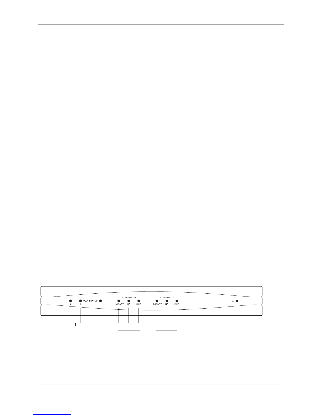
AR1202 Front Panel
The router front panel houses the system LEDs.
Figure 2.1 AR1202 Router Front Panel
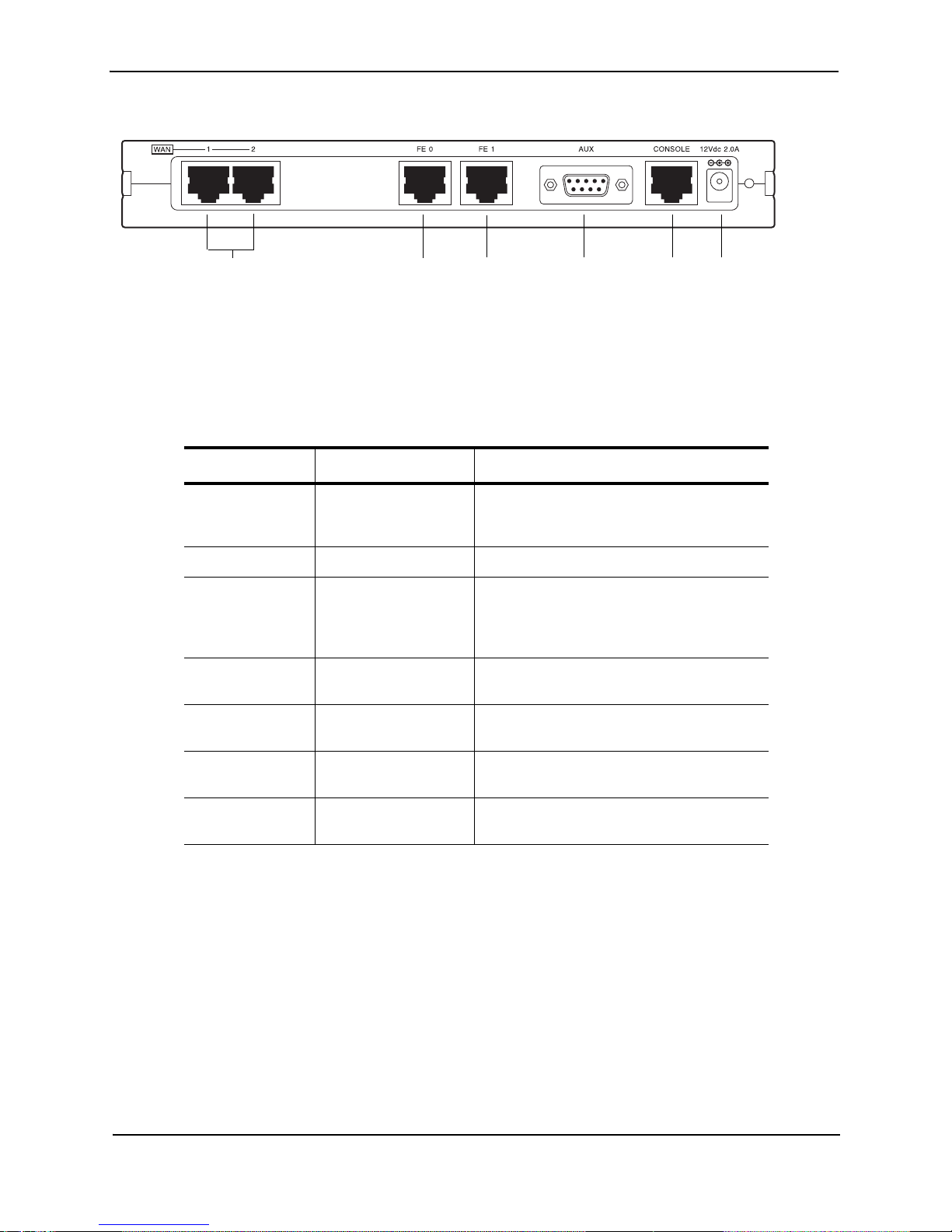
AR1202 Back Panel
The AR1202 router back panel provides connections for two WAN ports, two 10/100 Base-T Ethernet ports, one
AUX port, one Console port, and a 12 VDC power input jack.
WAN Port
LEDs 1-2
Ethernet 0 LEDs Ethernet 1 LEDs
Power LED
LINK/ACT HS
DUP LINK/ACT HS
DUP
Page 14
Foundry AR-Series AR1202 and AR1204 Installation Guide
2 - 2 © 2004 Foundry Networks, Inc. June 2004
Figure 2.2 AR1202 Router Back Panel
LEDs
The AR1202 front-panel LEDs indicate real-time unit status. Table 2.1provides information about how to interpret
the LED states.
Table 2.1: LED Descriptions
Port Description Color
WAN STATUS 1/ 2Indicates traffi c activity
on this interface
Green = normal activity
Red = alarm state
Yellow = test mode
ETHERNET 0 / 1
LINK/ACT Indicates traffic activity
on this interface
Green = link is operational
Blinking Yellow = either receiving or sending
traffic
Red = packet collisions
HS Indicates traffic speed
on the interface
Off = 10 Mbps
Green = 100 Mbps
DUP Indicates the type of
duplex mode
Off = Half duplex
Green = Full duplex
Foundry Logo Back lighted when
power is on
Blue
Power Indicates system
power status
Green = power on
Off = power off
WAN Ports 1 - 2 Fast Ethernet
Port 0
Fast Ethernet
Port 1
AUX Port
Console
Port
12 VDC
Input Jack
Page 15
Product In troduction
June 2004 © 2004 Foundry Networks, Inc. 2 - 3
AR1204
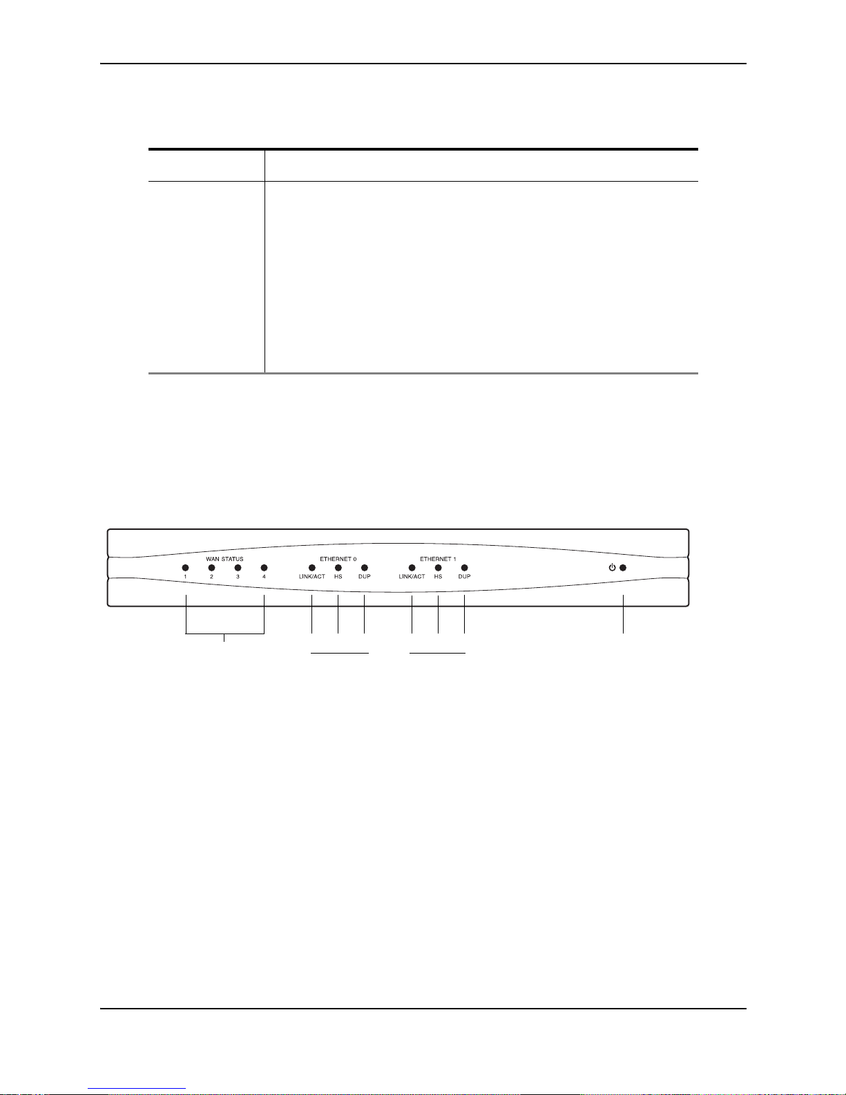
AR1204 Front Panel
The router front panel houses the system LEDs.
The following section identifies and describes the AR1204 router network ports and LEDs.
Figure 2.3 AR1204 Router Front Panel
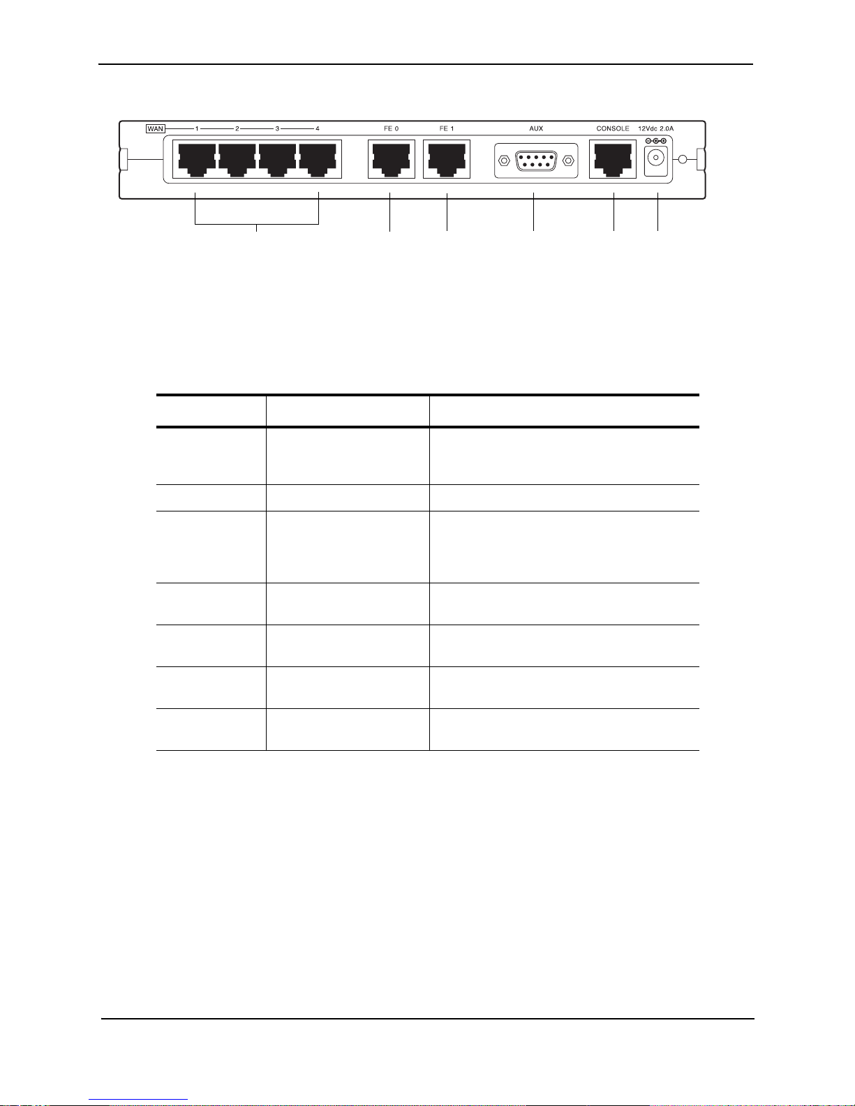
AR1204 Back Panel
The AR1204 router back panel provides connections for four WAN ports, two 10/100 Base-T Ethernet ports, one
AUX port, one Console port, and a 12 VDC power input jack.
Table 2.2: AR1202 Back-Panel Ports
Connector Description
WAN 1 - WAN 2 WAN connection ports. These ports accept cables with RJ-48C connectors.
FE 0 / 1 Ethernet LAN conne cti on po rts. These ports a cc ept c abl es wit h R J -45 ca bl e
connectors.
AUX Reverse telnet connection. This port accepts a cable with a male DB-9
connector.
Console Console management port. This port accepts a cable with an RJ-45 cable
connector.
DC power 12 VDC pow er con necti on. Th is port a ccept s the 2 mm. power connector on
the DC power supply cable that ships with the AR1202 router.
WAN Port
LEDs 1-4
Ethernet 0 LEDs
Ethernet 1 LEDs
Power LED
LINK/ACT HS
DUP
LINK/ACT HS
DUP
Page 16
Foundry AR-Series AR1202 and AR1204 Installation Guide
2 - 4 © 2004 Foundry Networks, Inc. June 2004
Figure 2.4 AR1204 Router Back Panel
LEDs
The AR1204 front-panel LEDs indicate real-time unit status. Table 2.3provides information about how to interpret
the LED states.
Table 2.3: LED Descriptions
Port Description Color
WAN STATUS
1-4
Indicates traffic a ctivity on
this interface
Green = normal activity
Red = alarm state
Yellow = test mode
ETHERNET 0/1
LINK/ACT Indicates traffic a ct ivi ty on
this interface
Green = link is operational
Blinking Yellow = either receiving or sending
traffic
Red = packet collisions
HS Indicates traffic speed on
the interface
Off = 10 Mbps
Green = 100 Mbps
DUP Indicates the type of
duplex mode
Off = Half duplex
Green = Full duplex
Foundry Logo Back light ed when power
is on
Blue
Power Indicates system power
status
Green = power on
Off = power off
WA N Ports 1 - 4 Fast Ethernet
Port 0
Fast Ethernet
Port 1
AUX Port
Console
Port
12 VDC
Input Jack
Page 17

Product In troduction
June 2004 © 2004 Foundry Networks, Inc. 2 - 5
Table 2.4: AR1204 Back-Panel Ports
Connector Description
WAN 1 - WAN 4 WAN connec tion p ort. Th ese p orts accept cabl es with RJ -48C conne ctors. If
drop and insert is configured, then ports 1 and 2 are reserved for that
feature.
FE 0 - FE 1 Ethernet LAN connection ports. T hes e ports accept cables wi th RJ -45 c abl e
connectors.
AUX Reverse telnet connection. This port accepts a cable with a male DB-9
connector.
Console Console management port. This port accepts a cable with an RJ-45 cable
connector.
DC power 12 VDC power connection . This port acc ept s the 2 mm. power connec tor on
the DC power supply cable that ships with the AR1204 router.
Page 18

Foundry AR-Series AR1202 and AR1204 Installation Guide
2 - 6 © 2004 Foundry Networks, Inc. June 2004
Page 19

June 2004 © 2004 Foundry Networks, Inc. 3 - 1
Chapter 3
Installation
This chapter describes how to install and prepare the Foundry AR1202 and AR1204 router for operation.
Information is also provided describing the system front and back panels, operator interface, how to mount the
chassis, and how to connect network and power cables.
Before you insta ll the AR1202 and AR120 4, familiarize yoursel f wit h the network interface a nd pow e r c on nec tio ns
described in this chapter.
Site Preparation
Before installing a Foundry AR1202 and AR1204 router, ensure that the site conditions comply with the following
requirements and that the mounting equipment, tools, and cables are available at the installation site.
Environment
Site location is import a nt for the proper operation of the AR120 2 a nd AR1204 router. Place the unit in a cl ean , dry
environment with a dequa te air circ ulatio n. Allo w ad dition al cleara nce aro und the sys tem fo r foot tra ff ic and acce ss
to cable connectors on the rear panel.
Figure 3.1 shows the convect ion cooling ven ts on top of the unit . To prevent an over-temperature condition, whi ch
could result in system failure or performance degradation, make sure that these vents are not obstructed.
NOTE: In normal operation, the router will be warm to the touch.
Figure 3.1 Chassis Air Flow
CAUTION: Do not stack routers on top of each other. Doing so will defeat the convection cooling ability of the
router and such action could lead to equipment damage.
Refer to “Specifications” on page A-1 for more information about environmental requirements.
Page 20

Foundry AR-Series AR1202 and AR1204 Installation Guide
3 - 2 © 2004 Foundry Networks, Inc. June 2004
Power Requirements
The AR1202 and AR1204 router operates on 12 VDC power. A 12 VDC power supply and an AC power cord are
shipped with the router.
Network Connection
To successfully complete the installation, the router must be connected to a network. Before you start the
installation, make sure that a live network connection is available at the installation site.
Cables Required
The AR1202 and AR1204 router ships with a Console cable. You will need to obtain additional cables for your
specific application. The following additional cables are required to install the AR1202 and AR1204 router.
• One or two RJ-45, male/male, category 5, 26 AWG (minimum), twisted-pair, straight-through cable (Ethernet
LAN connection)
See Table A.8 on page A-6 for cable pinout information.
Refer to Figure 3.2 on page 3-2 to identify this cable.
Figure 3.2 Ethernet Cable
• One or two RJ-48C, male/male, category 5, 26 AWG (minimum), twisted-pair, straight-through WAN cable
See Table A.9 on page A-6 for cable pinout information.
Refer to Figure 3.3 to identify this cable.
Figure 3.3 WAN Cable
Tools Required
The following tools are required to install the Foundry AR1202 and AR1204 router.
Figure 3.4 R e quired Tools
#2 Phillips screwdriver
#3 Phillips screwdriver 1/4 inch flat blade screwdriver
Page 21

Installation
June 2004 © 2004 Foundry Networks, Inc. 3 - 3
Unpacking and Inspecting
After opening the shipping carton, remove and save all packing materials and boxes.
NOTE: Save the packing materials. If you need to return the product, you will need to repack the unit with the
original packing materia l.
Check the packing slip and contents of the shipping carton to ensure that you have received the following items.
Figure 3.5 Items Shipped with the AR1202 and AR 1204 Router
Inspect the AR1202 and AR1204 and the shipping carton for damage that may have occurred during shipping. If
you discover dama ge or that items are mis si ng, co ntact Foundry Technical Support. Refer to the Foundry website
for contact information.
Foundry router (AR1204 shown) Quick Start Guide, CD ROM, product registration
card, and product wa rr a nty
Power supply RJ-45 Console cable
AC power cord Female Console cable to PC adapter
Power supply cord retainer bracket Male DB-25 modem adapter
Page 22

Foundry AR-Series AR1202 and AR1204 Installation Guide
3 - 4 © 2004 Foundry Networks, Inc. June 2004
Wall-Mounting Option
An optional wall-mounting assembly is available for mounting the AR1202 and AR1204 router on a vertical surface. The
wall-mount components are shipped in the same box with the AR1202 and AR1204 router, and are shown in the following
figure:
Figure 3.6 Wall-Mount Com p onents
Rack-Mounting Option
An optional rack-mounting tray is available for installing the AR1202 and AR1204 router in an equipment rack. The
following items are shipped in a separate carton:
Wall-mount bracket
Power supply strap
Router to wall-mount bracket screws: (4) 4-40 x
.250 inch Phillips pan head
Hollow wall anchors Wall-mount screws: (4) 6 x 1 inch Phi llips pan head
Page 23

Installation
June 2004 © 2004 Foundry Networks, Inc. 3 - 5
Figure 3.7 Rack-Mount Components
Installing the AR1202 and AR1204 Router
The AR1202 and AR1204 router can be installed on a table top, in a Telco equipment rack (using the optional
rack-mounting tray), or on a vertical surface (using the optional wall-mounting assembly). The router ships with a
Console cable. You will need to obtain additional cables for your specific application. Refer to Figure 3.2 on
page 3-2 and Figure 3.3 on page 3-2.
CAUTION: Do not block the cooling vents on the top of the unit.
NOTE: For problem-free operation, the router should be located in an area with adequate ventilation.
Table Top Installation
To install the AR1202 and AR1204 for operation on a table top, follow this procedure. Refer to Figure 3.8 on
page 3-6.
Rack Tray
(2) Rack Carriage Assemblies
2) Mounting Brackets
(4) Velcro Tie Wraps
(2 sets) Velcro Mounting Pads
4) 10-24 x .5 Phillips
Pan Head Screws for
Equipment Rack
(4) 10-24 x .5 Phillips
Pan Head Screws for
Equipment Rack
(6) 6-32 x .25 Phillips
Flat Head Mountin g
Bracket Screws
4) 4-40 x .25 Phillips
Pan Head Rack Carriage
Screws
Page 24

Foundry AR-Series AR1202 and AR1204 Installation Guide
3 - 6 © 2004 Foundry Networks, Inc. June 2004
Figure 3.8 Table Top Installation
1. Place the unit on the table surface.
2. Insert the DC power cable into the DC input jack on the front of the unit.
3. Attach the cable retai ne r bra ck et b ehi nd the molded strain reli ef o n t he pow e r su pply cable near the DC input
jack.
4. Engage and secure the captive screw on the retainer in the threaded hole adjacent to the input jack on the
router.
5. Connect the appropriate ends of the AC power cord to the power supply and a 110/120 VAC outlet.
NOTE: Ensure that the cables are router out of the way of foot traffic.
Wall-Mount Installation
Follow this procedure to attach the Foundry AR1202 and AR1204 router to a vertical surface. Refer to Figure 3.9
on page 3-6.
Figure 3.9 Wall Mounting the AR1202 and AR1204 Router
1. Attach the router to the wall mount assembly using four (provided) Phillips pan head 4-40 x .250 inch screws.
110/120 VAC Outlet
Cable Retainer
Threaded Hole
12 VDC Port
Page 25

Installation
June 2004 © 2004 Foundry Networks, Inc. 3 - 7
Ensure that the router is oriented in a manner that allows the LEDs to be visible.
2. Attach the assembly with the mounted router to the wall surface with four (provided) 6 x 1 inch Phillips pan
head screws and hollow wall plastic anchors.
NOTE: The provided hollow wall anchors are not designed for installation in hard walls. These anchors should
only be installed in a sheet rock (gypsum wall board) wall.
3. Fit the AC strap over the power supply and then place the power supply on the wall mount bracket within the
four locating tabs.
4. Engage and tighten the AC strap captive screw to secure the power supply to the wall mount assembly.
5. Attach the cable retainer to the DC power cord behind the molded strain relief on the cable.
6. Insert the DC power cable jack into the 12 VDC port on the back of the router.
7. Engage and tighten the captive s crew on th e cable reta iner in the thre aded ho le adja cent to the DC in put jac k
on the router.
8. Connect the appropriate ends of the AC cord to the secured power supply and a 110/120 VAC outlet.
Rack-Mount Installation
To mount the AR1202 and AR1204 in an equipment rack, follow this procedure. Refer to Figure 3.10.
Figure 3.10 Rack Mounting the AR1202 and AR1204 Router
1. Determine the mounting position for the rack tray in the equipment rack (front or mid mount) and attach the
mounting brackets using t he four (provided) 6-32 x .250 inch flat head Phillips screws.
2. Attach the router to the carriage assembly using four (provided) Phillips pan head 4-40 x .250 inch screws.
3. Engage the carriage assembly in the rack tray rails and slide the assembly all the way in.
4. Fit the AC strap over the power supply and then place the power supply on the rack tray between the raised
tab and the back edge of the tray.
5. Engage and tighten the AC strap captive screw to secure the power supply to the rack tray.
6. Attach the cable retainer bracket to the DC power cord behind the molded strain relief on the cable.
7. Insert the power cable jack into the 12 VDC port on the back of the router.
Page 26

Foundry AR-Series AR1202 and AR1204 Installation Guide
3 - 8 © 2004 Foundry Networks, Inc. June 2004
8. Engage and tighten the captive screw on the cable retainer bracket in the threaded hole adjacent to the DC
input jack on the router.
9. Coil the excess cable and secure it on the tray behind the router.
10. Mount the tray in the equipment rack using either four (provided) Phillips pan head 10-24 x .5 inch screws or
four (provided) Phillips pan head 12-32 x .5 inch screws, whichever fits the equipment rack.
1 1. Connect the net wo rk ca ble s t o th e ro uter. Secure th e c abl es in the c lips located on the b otto m of the carriage
assembly. Refer to “Network Connections” on page 3-8.
12. Connect the appropriate ends of the AC cord to the secured power supply and a 110/120 VAC outlet.
13. Using a small fl at blade screw driver, engage and tighten the cap tive screw to se cure the carria ge assemb ly to
the rack tray.
Network Connections
The following sections describe how to connect various network cables to the Foundry AR1202 and AR1204
router.
Connecting the Ethernet Cable
The front panel on the router accommod ate s o ne L AN co nn ect ion s. Us e a c ateg ory5, twisted- p ai r Eth ernet cable
with RJ-45 connectors to connect to the LAN. Refer to Figure 3.2 on page3-2 to identify this cable.
Follow this procedure to connect the AR1202 and AR1204 to an Ethernet LAN network.
1. Connect the RJ-45 connector of a category 5 rated Ethernet cable to either the Ethernet 0 port on the back
panel.
2. Connect the RJ-45 connector on the other end of the cable to the LAN port.
Make sure that the cable connectors are locked and secure in the ports. See Table A.8 on page A-6 for pinout
information about this cable.
Figure 3.11 Connecting the Ethernet Cable
Connecting the WAN Cable
The back panel accommodates up to two WAN (model specific) cables. Use 26 AWG (minimum) category 5,
twisted-pair cable with RJ-48C connectors for this interface. Refer to Figure 3.3 on page 3-2 to identify this cable.
CAUTION: To reduce th e risk of fire, use only number 26 AWG or larger U L L ist ed or CSA C e rtifi ed Telecommunication Line Cord for all network connections.
Follow this procedure to connect a WAN port to the network:
1. Insert the RJ-48C connectors on one end of one cable in the appropriate port on the Service Provider’s
demarcation point.
Ethernet LAN Port
Fast Ethernet Port 0
Fast Ethernet Port 1
Page 27

Installation
June 2004 © 2004 Foundry Networks, Inc. 3 - 9
2. Insert the RJ-48C connectors on the other ends of the cables in the WAN ports on the front panel of the
Foundry router.
Make sure that the cable connectors are locked and secure in the ports. See Table A.9 on page A-6 for pinout
information about this cable.
Figure 3.12 Connecting the WAN Cable
Connecting Drop and Insert Cables
WAN ports 1 and 2 can alternatively be used for drop and insert traffic. Port 1 is designated for voice; port 2 is
used for data traffic. Use two 26 AWG (minimum) category 5, twisted-pair cables with RJ-48C connectors to
establish this connectivity.
Figure 3.13 Connecting Drop and Insert Cables
To connect drop and insert cables, follow this procedure. Refer to Figure 3.13 on page 3-9.
1. Insert the RJ-48C connector of one end of one WAN cable in WAN port 1 on the router.
2. Connect the other end of this cable to the local PBX port.
3. Insert the connector on one end of the second cable to WAN port 2 on the router.
4. Connect the other end of this cable to the Service Provider’s demarcation point.
5. For information about configuring drop and insert, refer to the Command Reference Guide.
Operator Interface
Local Management
The AR1202 and AR1204 can be locally configured, operated, and managed using an operator console
connected to the Console port. A terminal (VT-100 or equivalent) or workstation with terminal emulation software
can be used for the operato r co ns ole . C onn ec t the conso le to the AR1 202 and AR120 4 router Console port using
an RJ-45 cable with switched ends. If your terminal equipment requires a special cable, see Table A.7 on page A5 for connector pinout information.
To connect the Console cable:
Connect to Service
Provider’s Demarcation
Point
WAN Port 1
Connect to Service Provider’s
Demarcation Point
Connect to the Local PBX Port
RJ-48C WAN Cables
Page 28

Foundry AR-Series AR1202 and AR1204 Installation Guide
3 - 10 © 2004 Foundry Networks, Inc. June 2004
1. Connect the RJ-45 Consol e cable to the Console port on the router.
2. Connect the other end of the RJ-45 Console cable to the RJ-45 end of the adapter.
3. Connect the DB-9 end on the adapter to the management terminal or workstation.
Figure 3.14 Connecting the Console Cable (Local Management)
Remote Management
A modem can be connected to the Console port and used to configure, operate, and manage the AR1202 and
AR1204 remotely.
Figure 3.15 Connecting a Modem for Remote Management
Follow this procedure to connect the AR1202 and AR1204 to a modem. Refer to Figure 3.15 on page 3-10.
1. Connect the male end of the DB-25 adapter to the female DB-25 port on the modem.
2. Connect one end of a supplied RJ-45 cable to the RJ-45 port in the DB-25 adapter.
3. Connect the other end of the RJ-45 cable to the Console port on the AR1202 and AR1204.
4. Refer to the Foundry Support website for modem configuration information.
If a workstation is used for the remote management console, use VT-100 terminal emulation software or
equivalent, and configure the software as specified for modems.
Console Messages
Alarm messages a re d is pla ye d at the console whe n system logging is c onfi gu r ed. R efe r to th e confi gure system
logging console command and related system logging commands in the Command Reference Guide for more
information about how to configure specific alarm events.
For more information about command usage for T1 and E1 products, refer to the Command Reference Guide.
This guide is available on the Foundry website.
RJ-45 to DB-9 Adapter
Console Port
Console Port
Modem
DB-25 Modem Adapter
Page 29

June 2004 © 2004 Foundry Networks, Inc. 4 - 1
Chapter 4
Configuration
This chapter desc ribes how to lo gin; chang e the defaul t p assw ord, config ure th e route r and users , and chang e the
factory default configuration. The boot process and software upgrade process is also discussed in detail.
Logging In
If you have not estab lis hed a local console conne ction, see “Operator Interf ace ” on page 3-9 for more information.
The following figure shows the login sequence and the initial prompt after login is complete.
Figure 4.1 Initial CLI Prompt
NOTE: The default host name is Foundry-model number, e.g., Foundry-AR1202#.
Command Tips
Use the following command tips and shortcuts with command line interface commands.
• To display all commands, type tree.
• To access help associ ated with a c omman d, type help <command name>. You may also use the ? key after
any command.
• To exit back one level in the command hierarchy, type exit and press Return.
• To exit the command mode and/or return to the base CLI prompt, press the key combination Ctrl-Z.
• Type the first two letters of a command, and then press the Tab key to automatically spell out the command.
• Scroll through the available commands using the Tab key.
Initial CLI Prompt
login: username
password:
username logged in on Fri May 7 05:28:01 2004
from console
Foundry CLI
foundry-model#
Page 30

Foundry AR-Series AR1202 and AR1204 Installation Guide
4 - 2 © 2004 Foundry Networks, Inc. June 2004
Ethernet Configuration Tip
To avoid Ethernet mismatch problems, the AR1202 and AR1204 router and the network device to which it is
attached should both be configured identically for speed and duplex. For example, if the router is configured for
auto-negotiation and the far end is configured manually, the router detects the speed, but defaults to half-duplex
mode. To ensure correct operation, either manually configure each device for speed and duplex settings, or
configure both devices to auto-negotiate.
Changing Login Parameters
The System Administrator login consists of two components: the user name and the password. The initial login
name is always foundry, but you can change this to suit your needs after logging in for the first time. The default
password for user Foundry, foundry, should be changed as soon as possib le to ensure only autho rized ac cess to
the router.
For more information about command usage for T1 products, refer to the Command Reference Guide: Domestic
Products. For information about command usage for E1 products, refer to the Command Reference Guide:
International Products. These guides are available on the Foundry website.
Password
This procedure e nables the syste m admin istrato r to c hange any o r al l use r p assword s, or any u ser to ch ange t heir
password on the AR1202 and AR1204. The password must be 3-10 characters.
To change the password:
1. Access the password configuration mode.
example:
Foundry-AR1202# password
The system prompts for the current user name.
2. Type foundry, and then press Return.
The system prompts for the old password.
3. Type foundry, and then press Return.
The system prompts for the new password.
4. Type your new password, and then press Return.
The system prompts you to verify the new password.
5. Type the new password again and then press Return.
A message is appears confirming that the password has been changed.
Administrator Account
This procedure changes the administrator login name (Level 1 access) to a user-specified name. The default is
foundry.
To change the account name:
1. Access the configure mode.
example:
Foundry-AR1204# configure term
2. Change the account name.
example:
Foundry-AR1204/configure# admin_name Greg
This example above changes the Level 1 user name to Greg.
The system displays a confi rming message : “ Administrator account name changed to Greg.”
Page 31

Configuration
June 2004 © 2004 Foundry Networks, Inc. 4 - 3
NOTE: Changing the adm inistrato r login n ame does not chan ge the ad ministra tor’s pas sword. Use the pa ssword
procedure to change the password.
System Host Name
Use the configure hostname command to assign a host name to the Foundry router. Once assigned, the host
name becomes the command line interface (CLI) prompt name.
To configure the host name:
1. Access the terminal configuration mode: Foundry-AR1204# configure term
2. Type hostname, and then type a new host name.
3. Press Return.
example:
Foundry-AR1204/configure# hostname Fremont
In the above example, the new host name for the system is Fremont. The CLI prompt changes to Fremont,
accordingly.
example:
Fremont/configure#
Date and Time
Date and time is set using the configure date command. You must specify the offset direction, hours, and
minutes before entering the exact date and time. The number of hours and minutes is offset from (earlier than or
later than) a Universal Time Coordinated clock (UTC).
NOTE: Universal Time Coordinated (UTC), the internationally recognized measure of time, is also known as
Greenwich Mean Time (GMT).
To set the date and time:
1. Enter the terminal configuration mode: Foundry-AR1204# configure term
2. Press Return.
3. Use the date command to enter the hours and minutes offset from UTC, followed by the current month, day,
year, hour (24-hour format), minute, and second.
To enter the date and time: May 10, 2004, 2:40:35 pm, see the following example:
example:
Foundry-AR1204/configure# date + 0 0 mo 5 d 10 y 2004 h 14 mi 40 s 35
NOTE: The hour, minute, and second entries are optional.
The router confirms the setting by automatically displaying the date and time. To confirm the date and time
parameters, use the display date command.
Adding Users
The configure user command allows the system administrator to add up to 15 users (login ID) and assign each
user an access privilege (levels 2-4). Only the system administrator (level 1) can add, modify, or remove this
information.
To add a new user:
1. Enter the terminal configuration mode: Foundry-AR1204# configure term
2. Type user name, enter the name that you want to add, and th en enter th e acce ss level to be assi gned to th at
name (optional). The user name may be up to 30 characters. The password must be 3-10 characters.
Page 32

Foundry AR-Series AR1202 and AR1204 Installation Guide
4 - 4 © 2004 Foundry Networks, Inc. June 2004
example:
Foundry-AR1204/configure# user John level 2
The system prompts you to enter a new password.
3. Enter the new password.
The system prompts you to re-enter the new password.
4. Re-enter the new password.
The system confirms that the password is set and confirms the name of the added user.
You can use the display user_accounts command to view user information.
Removing Users
The no use r name com mand all ows the sy stem adm inistrato r to remov e configu red user names fr om the Fou ndry
system.
To remove a user name:
1. Type no user name, followed by the user’s name.
example:
Foundry-AR1204/configure# no user John
2. Press Return.
The user name is removed from the system.
Default Configuration
For more information abou t com mand us age, re fer to the ap propria te Fou ndry Co mman d Re ference G uide (eithe r
the domestic or international version).
There are three ways to restore factory default configuration settings. Remember to reboot the router after
performing any of the following procedures.
• Clear the contents of the system.cfg file
clear cfg_fil e system.cfg
• Delete the system.cfg file
rm system.cfg
• Rename and remove the system.cfg file
copy system.cfg system.bk
rm system.cfg
After performing any of the above options, the system.cfg file no longer exists. Subsequently, a “file not found”
error message is displayed upon rebooting the system. This message will not impact operation, and it should be
ignored.
NOTE: If you change any of the factory default settings, issue the save local command to retain the changed
configuration before r ebo otin g.
The following tables show the factory default configuration for the Foundry AR1202 and AR1204 router.
Page 33

Configuration
June 2004 © 2004 Foundry Networks, Inc. 4 - 5
T a ble 4.1: Defau lt Configurati on Values
Parameter Default
speed auto (negotiates 10 Mbps or 100 Mbps)
address uses the current address stored in the system.cfg file (if one exists),
otherwise an IP address must be configured from the command line
interface
duplex auto (negotiates half-duplex or full-duplex)
Table 4.2: Default IP Routing Settings
Parameter Default
IP routin g
1
disabled
IP multiplexing
2
enabled
1, 2 IP routing and IP multiplexing are mutually exclusive of each other. Only one
can be enabled at a time.
Table 4.3: Default Telecommunications Values
Parameter Default Value Optional Values
framing esf d4
linecode b8zs ami
clock_source internal line
linemode csu dsx
lbo 0 dB 7.5 db
15 db
22.5 db
cable length 1 (0 - 110 ft.) 2 (110 - 220 ft.)
3 (220 - 330 ft.)
4 (330 - 440 ft.)
5 (440 - 550 ft.)
6 (550 - 660 ft.)
fdl ANSI and ATT unit protocol
enabled
ANSI (only)
ATT (only)
yellow_alarm disabled generate
detect
generate and detect
Page 34

Foundry AR-Series AR1202 and AR1204 Installation Guide
4 - 6 © 2004 Foundry Networks, Inc. June 2004
Configuring Drop and Insert Multiplexing
To use this feature, WAN ports 1 and 2 must be active and licensed for use. Drop and insert supports one-to-one
mapping of 1 to 24 voice-carrying DS0s on the PBX interface to the equivalent DS0s on the network port. The
PBX is connected to WAN port 1 and the DS0s are mapped to the carrier facility on WAN port 2.
In this example, DS0 channels 1-10 and 18-24 from WAN links 1 and 2 are configured for drop and insert traffic.
The remaining DS0 channels (11-17) are available for IP traffic.
Configure the drop_insert interface
The interface name can be a maximum of 8 characters.
Configure the mode type
The mode type can be one of the following three values:
0 data only (default)
1 data and voice
2 voice only
Table 4.4: E1 Interface Default Configuration
Parameter Default Value Optional Values
framing crc non-crc
disabled
linecode HDB3 no optional value
clock_source internal line
linemode short_haul long_haul
jitter enabled disabled
lbo 43 db 12 db
yellow_alarm generate and detect no optional value
Table 4.5: Terminal Emulation Defaults
Setting
9600 bps
8 data bits
1 stop bit
no parity
XON/XOFF flow control
host/configures interface drop_insert Foundry
Page 35

Configuration
June 2004 © 2004 Foundry Networks, Inc. 4 - 7
Note that “2” represent s port 2. This is the o nly va lue tha t wil l be accep ted . The “1” rep resen ts th e mode (data and
voice) for which port 2 is configured.
Display interface drop_insert Foundry
Configure the link
The default value for timeslots is all (available). Signaling can be configured for:
1 RBS (default)
2ISDN
Display interface drop_inserts
host/configures interface drop_insert Foundry mode 2 1
host# show interface drop_insert Foundry
drop_insert Foundry
-----------------------
number of links 0
host/configures interface/drop_insert Foundry# t1 1 2 timeslots 1-10,10-24 signaling 1
host# show interface drop_inserts
drop_insert table
-----------------Foundry
Link Usage Summary:
Page 36

Foundry AR-Series AR1202 and AR1204 Installation Guide
4 - 8 © 2004 Foundry Networks, Inc. June 2004
Display interface drop_insert Foundry
Switching Routing/IPMUX Modes
To switch between IPMux and dynamic routing modes, a valid software license must be installed on the AR1202
and AR1204 router. Contact Foundry and provide the serial number for the router.
Switching to Routing Mode
To switch from IPMux to dynamic routing mode, issue the following command:
Foundry-AR1204/configure# system routing
A message is displayed warning you to issue the save local command before the router reboots and you must
confirm that you want to change to routing mode. Enter Y and press the Return key. The AR1202 and AR1204
reboots into dynamic routing mode.
Switching to IPMux Mode
To switch from dynamic routing to IPMux mode, issue the following command:
Foundry-AR1204/configure# no system routing
A message is displayed warning you to issue the save local command before the router reboots and you must
confirm that you want to change to IPMux mode. Enter Y and press the Ret urn key. The AR1202 and AR1204
reboots into IPMux mode.
Boot Process
When power is applied to the Foundry system, the Flash is checked for a downloadable boot image. If a boot
image file is found in the Flash, the fil e is execute d. Otherw ise, the boot image is ex ecuted from the facto ry image
stored in the boot ROM. Next, the Foundry operating system is loaded from the AR01_#### file residing in the
Flash. Power-up diagnostics such as flash test, memory test, etc. are run and then the Ethernet and WAN
interfaces are installed. The router is then configured using settings previously saved in the system.cfg file. Once
these settings are configured, the router is ready for operation and user login.
Upgrading System Software
The Foundry command line interface (CLI) provides commands that allow you to upgrade the AR1202 and
AR1204 router with new software. Every system is furnished with a software image file (AR01_####) and a boot
image file (T1000.bin). Using the TFTP protocol, the latest versions of these files can be loaded onto a Foundry
router from any accessible TFTP server.
host# show interface drop_insert Foundry
drop_insert Foundry
-----------------------
number of links 2
Interface Mode: DATA AND VOICE MODE
Signaling Type: RBS
Page 37

Configuration
June 2004 © 2004 Foundry Networks, Inc. 4 - 9
A software upgrade consists of two files: AR01_#### and T1000.bin. The .Z file is the operating system for the
Foundry system; the .bin file contains the downloadable boot images.
NOTE: Foundry systems do not support two simultaneous downloads.
NOTE: Refer to the appropriate Command Reference Guide (domestic or international products) for specific
command parameters, options, and context.
Before Downloading the AR01_#### File
If you must issue the file download command, do so only when the source of the download file is currently
answering a ping command and there is no immediate concern about unscheduled power outages. This situation
is a cause for concern because a problem can arise when there is insufficient Flash space to hold a backup copy
of the downloaded AR01_#### file. When this occurs, the system prompts for approval to continue. However, if
power fails or there are netw o rk p rob lem s d uri ng th e fi le d ow nl oad , th e sy s tem ma y n ot be ab le to boot from flash
because the file may be incomplete or corrupt. If this occurs, you can boot using FTP. Refer to “Booting From a
Network TFTP Server” on page 4-10 for this procedure.
Upgrading Software
To upgrade the AR01_#### and T1000.bin files:
1. Download AR01_#### and T1000. bin from the Fo undry Su pport p age o n the web site a nd plac e it on a serv er
that is running a TFTP daemon.
2. Ensure that network connectivity exists between the Found ry sy ste m bei ng upg rade d and the TFTP server
holding the new file. Pinging the server from the Foundry system is a good method to use to prove
connectivity.
3. Download files to the Flash. The general format for the download commands is:
file download server_ip source_file local_file
server_ipThe IP address of the server holding the upgrade files.
source_filePath and file name of the file to be downloaded.
local_fileFile name to be used in local flash memory.
For example, a typical sequence might consist of:
• downloading all files to the main board:
file/download 10.10.1.1 r7/AR01_#### AR01_####
file/download 10.10.1.1 r7/T1000.bin T1000.bin
4. Move the .bin images to the downloadable boot area:
file/copy_boot T1000.bin
file/validate_boot T1000.bin (This should validate the copy_boot procedure.)
5. Make sure you are booting the images from the Flash and then reboot the system:
configure# boot AR01_####
Then type “Y” to reboot the router.
6. After reboot, log in and verify the proper software version with the following command:
display version
Page 38

Foundry AR-Series AR1202 and AR1204 Installation Guide
4 - 10 © 2004 Foundry Networks, Inc. June 2004
Booting From a Network TFTP Server
In the rare and unlikely situation where a software version upgrade fails, a network boot may be performed as
described in the following procedure.
1. Assume that the new AR01_#### download failed when the following command was issued:
This command li ne is ap prop riate when the new u pgr ade AR01_#### file res ide s on a tftp serve r h os t with IP
address 192.168.10.1, in a directory named tftpdir/8.0.
Upon a download failure (a nd corruptio n or deletion of the AR01_### # file in Flas h), the AR1202 an d AR1204
router may not be able to boot.
2. Make note of which Ethernet interface (0 or 1) connects the system to the tftp server host.
3. Connect a terminal or ter m inal emulator to the console port of the Foundr y system using the cable supplied.
Configure the terminal for 9600 bps, 8 data bits, 1 stop bit, no parity, and XON/XOFF flow control.
4. Power cycle the AR1202 and AR1204.
5. Press and hold the Enter (Return) key while the system boots (usually 10-15 seconds).
6. The following (or similar) text is output to the terminal:
7. Type c, and press the Enter key.
NOTE: At any point in this procedure, online help can be accessed by typing ? and pressing the Enter key.
8. If Ethernet 0 is connected to the tftp server host, change fl0 (flash boot) to InPci0.
The following text is output to the terminal:
9. Press the Enter key.
Router# file download 192.168.10.1 tftpdir/8.0/AR01_####
Copyright (c)
Copyright (c)
CPU: Foundry
Variation: 8.3.2
RSP Version 1.1/2
Creation date Sep 8, 2000, 19:14:24
Press any key to stop auto-boot....
1
[Foundry Boot. reboot in 1 minute if CR not pressed]:
[Foundry Boot]:
[Foundry Boot]:
.
.
.
[Foundry Boot]:
[Foundry Boot]: c
‘_’= clear field; ‘=’ = go to previous field; ^D = quit
boot device : f10 InPci0
processor number ) 0
Page 39

Configuration
June 2004 © 2004 Foundry Networks, Inc. 4 - 11
The following text is output to the terminal:
10. To keep this parameter, press the Enter key.
The following text is output to the terminal:
11. Enter the path-qualified file name: type /tftpdir/r4.6/AR01_#### (or whatever is consistent with the file
download command in the above example) and press the Enter key.
The following text is output to the terminal:
12. Input the address for the Foundry system to use as an tftp client to the tftp host. Type 111.2.3.3:ffffff00 (or
whatever is appropriate for your network configuration) and press the Enter key.
Note that the netmask is specified in hexadecimal after a colon (here a 24-bit netmask). You must be in the
same subnet as the tftp host or the same subnet as the default router through which you will access the tftp
host.
The following text is output to the terminal:
13. Press the Enter key. The following text is output to the terminal:
14. At this point, the tftp host address must be entered. Type 192.168.10.1 (or whatever is consistent with the
downloadNCM command in the above example) and press the Enter key.
The following text is output to the terminal:
15. If a gatew ay does not exist between the Foundry router and the tftp server, then this can be left blank.
However, it is required if the router and the tftp server reside in different subnets. For this example you would
enter 111.2.3.254.
The following text is output to the terminal:
16. Make sure to type wind. Then set the password also to wind. Press the Enter key.
The following text is output to the terminal:
17. Set the flags. Type 0x8a. Press the Enter key.
host name : host
file name : /flash1/T2000.Z
1net on ethernet [e] : 10.1.0.1:fff0000
1net on backplane [b] :
host 1net [h] : 10.11.12.13
gateway 1net [g] : 10.11.12.13
user [u] : wind
ftp password [pw] [blank = use rsh] : wind
Page 40

Foundry AR-Series AR1202 and AR1204 Installation Guide
4 - 12 © 2004 Foundry Networks, Inc. June 2004
The following text is output to the terminal:
Set the target name. Press the Enter key.
The following text is output to the terminal:
The name that you use to configure the Foundry router will become the system prompt.
Ensure that the startup script parameter is blank. The “other” parameter may be blank or left as “inPci.”
After entering all the parameters described above, the Foundry boot prompt, “[Foundry Boot]” is displayed.
18. Verify that the settings are correct. Press the Enter key to display the following text:
19. Type @ and press the Enter key to boot from the network.
20. Download the new images. Refer to “Upgrading Software” on page 4-9.
flags [f] : Ox8a
target name [tn] :T1200
[Foundry Boot]: P
boot device
: InPci
unit number : 0
processor number : 0
host name : host
file name :
tftpdir/8.0/T2000.Z
1net on ethernet [e] : 10.1.0.1:fff0000
host 1net [h] : 10.11.12.13
gateway 1net [g] : 111.2.3.254
user [u] : wind
ftp password [pw] : ****0
flags [f] : 0x8a
target name [tn] : T1200
ether [e] : InPci
Page 41

June 2004 © 2004 Foundry Networks, Inc. A - 1
Appendix A
Specifications
This appendix includes technical information about the operating environment, power application, interfaces,
cable pinouts, MIBs, and physical cables and adapters used to connect the Foundry AR1202 and AR1204 router
to a network.
System Specifications
The following tables provide various technical specifications for the Foundry AR1202 and AR1204 router.
Table A.1: Environment, Hardware, Memory, and Power
Environment
Operating temperature 32° F to 104° F (0° C to 40° C)
Storage temperature –32° F to 158° F (0° C to 70° C)
Relative humidity 5 to 90%, non-condensing @ 104° F (40° C)
Altitude 0 to 13,123 ft. (0 to 4,018 meters)
Dimensions
Height 1.32 inches (3.35 cm)
Width 8.65 inches (21.97 cm)
Depth 6.61 inches (16.79 cm)
Weight 1.5 lbs (.675 kg)
Memory
Default 256 MB DRAM
Default 16 MB Flash
Storage for multiple configurations
AC Power
Page 42

Foundry AR-Series AR1202 and AR1204 Installation Guide
A - 2 © 2004 Foundry Networks, Inc. June 2004
Frequency range 50 to 60 Hz
Nominal voltage range 100 to 240 V RMS
Average power
consumption
15 watts
DC Power
Voltage range +12 VDC
Average power
consumption
11.52 watts
Ta ble A.2: Performance Monitoring
Statistics Storage
Statistics for the last 24 hours in 15-minute increments
Statis tic s for 24-h our incr ements
Reporting
G.821 performance reports
Alarm history
Interface statistics
Alarms
RRAI receive yellow
TAIS transmit alarm indication signal
TRAI transmit yellow
RAIS receive alarm indication si gnal
RLOF receive loss of frame
LORC loss of receive clock
RLOS receive loss of signal
Threshold alarms
Table A.1: Environment, Hardware, Memory, and Power
Page 43

Specifications
June 2004 © 2004 Foundry Networks, Inc. A - 3
WAN Interfaces
The following tables provide specifications for T1 WAN and E1 WAN interfaces.
Table A.3: T1 WAN Interface
Receive line rate 1.544 Mbps ± 32 ppm
Line code b8zs or ami
Framing d4 or esf
Interface ESF FDL AT&T TR-54016-1986
A T&T TR -54 016 -198 9
ANSI T1.403-1989
Input signal DSX-1
0 to – 24 db
Output signal 0
– 7.5 db
–15 db
Equalization 0 to 655 ft. (DSX-1)
Impedance 100 ohm
Connectors RJ-48C
Timing internal
network
Pulse density AT&T TR-62411; HDLC Inversion, forced
Page 44

Foundry AR-Series AR1202 and AR1204 Installation Guide
A - 4 © 2004 Foundry Networks, Inc. June 2004
LAN Interfaces
The following table provides information about Ethernet interface.
Table A.4: E1 WAN Interface
Receive line rate 2.048 Mbps ± 50 ppm (payload = 1.984 Mbps)
Line code HDB3
Framing crc
non-crc (ITU G.704)
unframed
Input sign al 0 to -32 db
Output signal ITUG.703
Impedance 75 ohm
120 ohm
Connectors RJ-48C
Timing internal
network
Table A.5: Specifications: Ethernet LAN Interface
Two 10/100 Base-T, 802.3 auto-negotiating, full or half-duplex
Table A.6: Miscellaneous
Service Levels and Connectivity
DS0
NxDS0
T1
E1
NxT1
NxE1
10/100 Base-T
Protocol Support
WAN
PPP
MLPPP
Page 45

Specifications
June 2004 © 2004 Foundry Networks, Inc. A - 5
Cable Pinouts
The following tables provide cable pinout information for the console (RJ-45), Ethernet (RJ-45), T1(RJ-48C), and
modem (DB-9 to DB-9) or (DB-25 to DB-9) cables.
HDLC
Frame Relay
Multilink Frame Relay (MFR)
FRF.15 (End-to-End)
FRF.16 (UNNI/NNI)
Management Interfaces
Console: RJ-45
AUX: DB-9
Table A.7: Pinouts: Foundry-to-Terminal Console Cable (DB-9)
Foundry
DCE Pin Signal Direction
Workstation
DTE Pin
1 data carrier
detect
<— 1
2 transmit data —> 2
3 receive data <— 3
4 data terminal
ready
—> 4
5 signal ground <—> 5
6 data set rea dy <— 6
7 request to
send
—> 7
8 clear to send <— 8
9 not used 9
Table A.6: Miscellaneous
Service Levels and Connectivity
Pin 5
Pin 1
Pin 9
Pin 6
RS-232 DCE on DB-9 Female
Page 46

Foundry AR-Series AR1202 and AR1204 Installation Guide
A - 6 © 2004 Foundry Networks, Inc. June 2004
Ta ble A.8: Pi nouts: Ethernet Cable (RJ-45)
Foundry
Pin Signal Direction
LAN
Signal
1 TxD+ —> TxD+
2 TxD– —> TxD–
3 RxD+ <— RxD+
4not
used
not
used
5not
used
not
used
6 RxD– <— RxD–
7not
used
not
used
8not
used
not
used
Table A.9: Pinouts: WAN Cable (RJ-48C)
Pin Signal
1 receive from network ring (R)
2 receive from network tip (T)
3 no connection
4 send toward network ring (R)
5 send toward network TIP (T)
6 not used
7 not used
8 not used
Table A.10: DB-25 to RJ-45 Modem Adapter Pinouts
RJ-45 Pin Signal DB-25 Pin
1 no connection 2 no connection 3RxD 3
4 Ground 7
Pin 8
Pin 1
Pin 8
Pin 1
Page 47

Specifications
June 2004 © 2004 Foundry Networks, Inc. A - 7
MIBs
Foundry systems support standar d and ente rprise MIBs. The fo llowin g tables prov ide inform ation about supported
MIBs.
5 Ground 7
6TxD 2
7 no connection 8 no connection -
Table A.11: Standard MIBS
Standard MIB Description
RFC 1213 Standard MIB-II objects.
The following groups or variables are not supported for this MIB:
•egp
•at
RFC 1315 MIB objects for frame relay DTE interface.
The following SNMP SET operation variables on frDlcmiTable are not
supported for this MIB:
•frDlcmiAddress
• frDlcmiAddrsssLen
• frDlcmiMaxSupportedVCs
• frDlcmiMulticast
RFC 1403 Defines the interoperability of using BGP as the border gateway routing
protocol and OSPF as the interior gateway routing protocol.
RFC 1406 MIB objects for DS1 interface.
The following Far End tables are not supported for this MIB:
• dsx1FarEndCurrentTable
• dsx1FarEndIntervalTable
• dsx1FarEndTotalTable
RFC 1643 MIB objects for Ethernet-like interface.
The following variables are supported for this MIB:
• dot3StatsFCSErrors
• dot3StatsDeferredTransmissions
• dot3StatsFrameTooLongs
The remainder are not supported.
Table A.10: DB-25 to RJ-45 Modem Adapter Pinouts
RJ-45 Pin Signal DB-25 Pin
Page 48

Foundry AR-Series AR1202 and AR1204 Installation Guide
A - 8 © 2004 Foundry Networks, Inc. June 2004
RFC 1657 Describes MIB objects used for BGP4 routing protocol.
RFC 1724 Describes MIB objects used for RIP routing protocol.
RFC 1850 Describes MIB objects used for OSPF routing protocol.
RFC 1997 Facilitates and simplifies the control of routing information. This rfc
suggests a gro uping of d estinatio ns so tha t the rou ting deci sion can also be
based on the identity of a group.
RFC 2096 Describes objects used for the display of CIDR multipath IP routes.
RFC 2233 MIB objects for interface table extensions including StackTable and
ifXTable. IfStackTable shows the sub-layer relationships of interfaces.
The following groups or variables are not supported for this MIB3:
• ifTestTable
• ifRcvAddressTable
• In the ifXTable, all High Counters (HC)(ifHC***) variables requiring 64bit counters are not supported.
RFC 2787 Describes MIB objects used for managing Virtual Redundancy Protocol
(VRRP) routers.
Table A.11: Standard MIBS (Continued)
Standard MIB Description
Page 49

Specifications
June 2004 © 2004 Foundry Networks, Inc. A - 9
Table A.12: Foundry Enterprise MIBs
Foundry MIB Description
bundle.mib Defines objects related to bundle and link configuration.
chassis.mib Defines objects related t o c ha ss is s eri al num be r a nd model number.
config.mib Defines objects related to saving configurations for network and
flash.
dsx-tc.mib Defines textual conventions for DSX MIBs. This MIB should be
compiled before any other DSX MIBs. This MIB does not contain
any objects that can be used for management operations.
dsx-te1.mib Defines objects for interface cards that support TE1. These include
configuration and statistics for ANSI/ATT/IETF and USER. These
objects only pertain to Layer 1.
environment.mib Defines environment-related objects, e.g., temperature, fans, etc.
ethernet.mib Defines objects related to configuration and statistics for Ethernet
interfaces.
fr.mib Defines object s related to confi guratio n and st atisti cs for fram e relay
and MFR bundles.
ghdlc.mib Defines objects related to configuration and statistics for generic
HDLC bundles.
ip.mib Defines objects related to IP addressable interfaces and static
routes.
ppp.mib Defines objects related to PPP/MLPPP bundles for configuration
and statisti cs.
products.mib Defines registration objects (sysObjectID) for various Foundry
products.
qos.mib Defines objects related to QOS monitoring and configuration. This
release contains only Random Early Detect (RED) objects and
class-based queuing.
smi.mib Defines the top-level object assignments for the Foundry MIB tree.
This MIB should be compiled before any other Foundry MIBs are
compiled. This MIB does not contain any objects that can be used
for management operations.
snmp.mib Defines objects related to SNMP community and trap_host
configurations.
system.mib Defines objects related to syst em informatio n, e.g., IP address , host
name, and DNS.
Page 50

Foundry AR-Series AR1202 and AR1204 Installation Guide
A - 10 © 2004 Foundry Networks, Inc. June 2004
Page 51

June 2004 © 2004 Foundry Networks, Inc. B - 1
Appendix B
Troubleshooting
This chapter provides general troubleshooting tips in addition to network tests and diagnostics information for the
Foundry AR1202 and AR1204 router.
Alarms and System Status
The AR1202 and AR1204 rou ter reports various ala rms upon de tecting cer tain irreg ular condi tions in the in coming
WAN signals. For more information about the command line interface and system commands, refer to the
appropriate Foundry Command Reference Guide (either the domestic or international version).
NOTE: The slot and/or interface numb er is requi red fo r com ma nds displa ying information on specific interf ace s.
If this information is not included when the command is issued, the system prompts for it. For more information
about a command, access command help by typing help <command name> and pressing Return.
To view alarms, use the appropriate derivative (T1/E1) of the following command:
• display module alarms t1
Use this command to view the current alarms for any T1 WAN link of the system.
You can display the current configuration and operating status of each WAN link using use the appropriate
derivative (T1/E1)of the following command:
• display module configuration t1
Use this command to view the current configuration of the selected WAN link, along with its line status.
WAN Statistics
In addition to WAN status and alarms, the router collects and stores various types of performance statistics. This
data helps you analyze the quality of a WAN link between the AR1202 and AR1204 router and the far-end WAN
equipment.
To display WAN statistics, use a derivative of the following command:
• display module userstats t1
Use this command to view user statistics gathered for the WAN interface.
Page 52

Foundry AR-Series AR1202 and AR1204 Installation Guide
B - 2 © 2004 Foundry Networks, Inc. June 2004
Network Tests
If the system is not workin g co rrec tly af te r veri fy ing that th e ca bl ing is corre ct between the Foundry router and the
external network equipment, run these basic tests to isolate the problem to the LAN port, WAN link, or serial
interface ports.
Ping Test
The Ping test checks connectivity between the Foundry system and another host system on the LAN. If an
“unknown host” error occurs after initiating this test, the destination host is either unreachable or unstable, or it
does not exist. If a 100 percent packet loss error occurs, the LAN is either down or unstable.
•ping
Use this command to check connectivity with another system.
Other Tests
To isolate problems with a fau lty WAN link, pe rform l ine or payload loop backs at either end of the l ink a nd perf orm
a BERT test. These functions isolate a problem to either the AR1202 and AR1204, far-end equipment,
interconnect cabling at either end, or the link between the two systems.
Loopback Test
To perform line and payload loopbacks at either end, use the appropriate derivative (T1/E1) of the following
commands.
The following loopback command is available.
• test t1 loopback
BERT Test
This command is used to ini tiate a bit error rat e test. The foll owing BER T test comma nd is availabl e to test spec ific
links.
• test t1 bert
The pattern parameter may have any of the following values:
Ta ble B.1: BERT Test Patterns
Pattern Description
2^11 Pseudorandom pattern with no more than 10 consecutive zeros and no
more than 11 consecutive ones.
2^15 Pseudorandom pattern with no more than 14 consecutive zeros and no
more than 15 consecutive ones. Use this pattern for testing at data rates
above 19.2 kbps (G.703-standard test).
2^23 Pseudorandom signal with no more than 22 consecutive zeros and no
more than 23 consecutive one s. This p attern provides the highes t stress of
all BERT patterns.
QRW Quasi-random waveform pattern (default). This pattern simulates live data.
Page 53

Troubleshooting
June 2004 © 2004 Foundry Networks, Inc. B - 3
Diagnostics Tips
The information in the following tables may help to isolate or resolve certain system problems.
General Symptoms
The following table provides general diagnostics information that applies the AR1202 and AR1204 router.
Table B.2: Common Symptoms and Actions
Symptom Cause Action
Power LED does not
illuminate with power
applied.
No power is
applied.
1 Verify that the AC power cord is functional.
2 Make sure the pow e r suppl y is w ork ing
properly.
3 Verify that the DC power cord is functional.
Power LED is
illuminated green, but
the terminal or
workstation
connected to the
system Console port
does not display a
CLI command promp t
or other text.
The connecting
terminal is faulty
or not configured
properly, the
interface cable is
faulty, or the
system Console
port is faulty.
1 Verify that the interface cable is connected
to the console port and that the cable is
properly assembled .
See Table A.7 on page A-5 for information
about the console cable.
2 Make sure the term in al is powe red up.
Ethernet LINK/ACT
LED is not
illuminated or
flashing.
The Ethernet LAN
is not active or the
LAN cable is
faulty.
1 Make sure the Ethernet LAN cable is
properly connected between the hub or
switch and the Foundry AR1202 and
AR1204 router.
2 If you are using a non-Foundry LAN cable,
refer to Table A.8 on pageA-6 to check the
cable pinouts.
3 Make sure bo th the router and the adjac ent
LAN nodes are powered on.
Ping test fails. The Ethernet LAN
is not working, the
destination host is
not responding, or
the LAN cable(s)
are faulty.
1 Make sure the Ethernet LAN cable is
properly connected between the hub or
switch and the Foundry router.
2 Make sure cables are properly connected
between the service p rov ider’s switc h, hub,
or LAN and the Foundry router.
3 If you are using a non-Foundry LAN cable,
refer to Table A.8 on pageA-6 to check the
cable pinouts.
4 Verify tha t the LAN i s properly con figured at
the command line. Also, check IP
addresses, subnetting, and routing
configurations.
5 Use the display arp command for target
addresses.
6 If excessive collisions exist on the LAN,
switch to a less congested LAN segment.
Page 54

Foundry AR-Series AR1202 and AR1204 Installation Guide
B - 4 © 2004 Foundry Networks, Inc. June 2004
WAN Status LED is
not illuminated.
The link is not in
service
Enable the link using the appropriate
derivative of the configure module t1 enable
command.
WAN Status LED is
red.
The link is faulty.
(The system has
detected an
abnormal
incoming signal.)
If a LOS (loss of signal) alarm is present:
1 Check the WAN cable connections to the
system. If you are using non-Foundry
cable(s), see Table on page A-5 for more
information.
2 If the cable is good, perform a BERT test
on the link.
3 If the BERT test passes, check the WAN
link between the two ends with external test
equipment. If the link is good, the Foundry
router is faulty.
WAN Status LED is
yellow.
The link is faulty
(far-end system
has detected an
abnormal
incoming T1
signal).
Perform the BERT te st (an d othe r step s above
from the far end) in conjunction with a T1 line
loopback at the Foundry router.
WAN Status LED
blinks green or
yellow.
The link is not
properly
configured at one
or both ends or it
is operating
marginally.
1 If frame errors are present, look for a
configuration mismatch between the
Foundry system and the far-end system.
2 If CRC-6 errors or BPVs are present, check
the Line Build Out (LBO) configuration
settings at both ends.
System cannot lock
onto a BERT pattern
from the far end.
The BERT test
has failed.
Try using another BERT pattern. If t he problem
continues, call your WAN service provider.
BERT error rate
exceeds 1% of
transmitted bits.
The link is faul ty or
deteriorating.
1 If an al l-ones or all-ze ros test is in progre ss,
check the Line Build Out (LBO)
configuration.
2 If a QRW test is in progress, check for the
same link configuration at the far end.
Table B.2: Common Symptoms and Actions (Continued)
Symptom Cause Action
Page 55

Troubleshooting
June 2004 © 2004 Foundry Networks, Inc. B - 5
System fails to boot,
and stops at [Fou ndry
Boot].
1 AR01_### # file
is non-existent
or has become
corrupt
2 Flash is
corrupt.
1 Connect your terminal to the Console port
on the Foundry router.
2 Config ure the modem for 9 600/8/None, and
no flow control.
3 Power cycle the Foundry router
continuously by press ing the Enter key until
you see the following pr ompt:
[Foundry Boot]
4 Type c, and press Enter.
5 The following prompts will be displayed.
Type the bolded entries and press Enter.
boot device: lnPci (Lower case “L”, not “1”.)
processor number: 0
host name: host
file name: “The path and file name on your
tftp server (e.g., tftpboot/NCM.Z)”
inet on ethernet (e): x.x.x.x:ffffff00 (This is
the system’s Ethernet address:netmask.)
inet on backplane (b): Not needed.
host inet (h): x.x.x.x (The ip address of the
tftp server.)
gateway inet (g): x.x.x.x (Your router’s
address- not necessary in the same
subnet.)
user (u): wind (This is a required field.)
ftp password (pw) (blank = use rsh): wind
(This is a required field.)
flags (f): 0x8a
target (tn): Foundry
startup script (s): Not needed.
other (o): lnPci (This i s a lo werca se “L ”, not
a “1”.)
6 At this point, you will be at the Foundry
prompt [Foundry Boot]. Type @ and press
Enter. This will boot the system from the
network.
7 Once the system is booted and you have
logged in, you must format the Flash by
issuing the following command:
file format NCM
8 When the format is complete, follow the
upgrade procedures to finish the process.
NOTE: Remember to connect to the TFTP
server that contains the AR01_#### file.
Table B.2: Common Symptoms and Actions (Continued)
Symptom Cause Action
Page 56

Foundry AR-Series AR1202 and AR1204 Installation Guide
B - 6 © 2004 Foundry Networks, Inc. June 2004
 Loading...