


Foundry FastIron SuperX, FastIron SX 1600-ANR, FastIron SX 800, FastIron SX 1600 Hardware Installation Manual

Foundry® FastIron X Series Chassis
Hardware Installation Guide
FastIron SuperX
FastIron SX 800
FastIron SX 1600
FastIron SX 1600-ANR
Release Date: December 16, 2008
FSX 05.0.00
Publish Date: December 31, 2008

Copyright © 2008 Foundry Networks, Inc. All rights reserved.
No part of this work may be reproduced in any form or by any means – graphic, electronic or mechanical, including
photocopying, recording, taping or storage in an information retrieval system – without prior written permission of
the copyright owner.
The trademarks, logos and service marks ("Marks") displayed herein are the property of Foundry or other third parties.
You are not permitted to use these Marks without the prior written consent of Foundry or such appropriate third party.
Foundry Networks, BigIron, Terathon, FastIron, IronView, JetCore, NetIron, ServerIron, TurboIron, IronWare, EdgeIron,
IronPoint, SecureIron, the Iron family of marks and the Foundry Logo are trademarks or registered trademarks of
Foundry Networks, Inc. in the United States and other countries.
F-Secure is a trademark of F-Secure Corporation. All other trademarks mentioned in this document are the property of
their respective owners.
Foundry Networks
4980 Great America Parkway
Santa Clara, CA 95054
Tel 408.207.1700
www.foundrynetworks.com

Contents
CHAPTER 1
BOUT THIS GUIDE..................................................................................... 1-1
A
INTRODUCTION ...........................................................................................................................................1-1
U
PDATES TO THIS MANUAL .........................................................................................................................1-1
A
UDIENCE ..................................................................................................................................................1-1
N
OMENCLATURE .........................................................................................................................................1-1
R
ELATED PUBLICATIONS .............................................................................................................................1-2
H
OW TO GET HELP .....................................................................................................................................1-2
W
EB ACCESS .......................................................................................................................................1-2
E-
MAIL ACCESS ...................................................................................................................................1-2
T
ELEPHONE ACCESS ............................................................................................................................1-2
W
ARRANTY COVERAGE ...............................................................................................................................1-2
CHAPTER 2
RODUCT OVERVIEW .................................................................................. 2-1
P
PRODUCT OVERVIEW ..................................................................................................................................2-1
H
ARDWARE BENEFITS ..........................................................................................................................2-1
POE P
S
S
OFTWARE FEATURES ................................................................................................................................2-3
POE A
S
UPPORT FOR IPV6 MODULES ....................................................................................................................2-3
IP
H
ARDWARE FEATURES ...............................................................................................................................2-4
FSX C
FSX 800 C
FSX 1600 C
FSX 1600-ANR C
M
S
December 2008 © 2008 Foundry Networks, Inc. iii
ORT DENSITY ............................................................................................................................2-2
UPPORTED CONFIGURATIONS .............................................................................................................2-2
PPLICATIONS ....................................................................................................................................2-3
V6 HARDWARE SUPPORT GUIDELINES ...............................................................................................2-3
HASSIS ......................................................................................................................................2-4
HASSIS ...............................................................................................................................2-5
HASSIS .............................................................................................................................2-7
HASSIS ....................................................................................................................2-9
ANAGEMENT MODULES ....................................................................................................................2-11
WITCH FABRIC MODULES (FSX 800 AND FSX 1600 ONLY) ...............................................................2-19

FastIron Hardware Installation Guide for the FSX, FSX 800, and FSX 1600
INTERFACE MODULES .........................................................................................................................2-19
N
ETWORK INTERFACES ......................................................................................................................2-25
P
ORT REGIONS ..................................................................................................................................2-26
P
OWER SUPPLIES ..............................................................................................................................2-27
C
OOLING SYSTEM ..............................................................................................................................2-32
B
UILT-IN MOUNTING BRACKETS ..........................................................................................................2-33
L
AYER 3 ROUTING PROTOCOL TABLE SIZES ..............................................................................................2-33
CHAPTER 3
INSTALLING THE CHASSIS ........................................................................... 3-1
SUMMARY OF INSTALLATION TASKS .............................................................................................................3-1
U
NPACKING A SYSTEM ................................................................................................................................3-2
I
NSTALLATION PRECAUTIONS .......................................................................................................................3-3
G
ENERAL PRECAUTIONS .......................................................................................................................3-3
L
IFTING PRECAUTIONS .........................................................................................................................3-3
P
OWER PRECAUTIONS AND WARNINGS .................................................................................................3-3
P
REPARING THE INSTALLATION SITE ............................................................................................................3-4
C
ABLING INFRASTRUCTURE ..................................................................................................................3-4
I
NSTALLATION LOCATION ......................................................................................................................3-5
R
EMOVING EXTRA SHIPMENT SCREWS (FSX AND FSX 800 ONLY) ...............................................................3-5
I
NSTALLING A CHASSIS IN A RACK ...............................................................................................................3-5
I
NSTALLING MOUNTING BRACKETS ON THE FSX 1600 CHASSIS .............................................................3-7
R
EMOVING THE SLOT PANELS .....................................................................................................................3-7
I
NSTALLING THE MANAGEMENT AND INTERFACE MODULES ...........................................................................3-7
A
TTACHING A MANAGEMENT STATION .......................................................................................................3-11
A
TTACHING A PC OR TERMINAL TO THE CONSOLE PORT OR 10/100/1000 COPPER PORT ....................3-11
A
TTACHING A SWITCH TO AN ETHERNET PORT ....................................................................................3-12
P
OWERING ON THE SYSTEM .....................................................................................................................3-12
C
ONNECTING AC POWER TO THE CHASSIS .........................................................................................3-13
C
ONNECTING DC POWER TO THE CHASSIS .........................................................................................3-14
V
ERIFYING PROPER OPERATION ...............................................................................................................3-16
O
BSERVING THE LEDS .......................................................................................................................3-16
D
ISPLAYING THE MODULE STATUS ......................................................................................................3-19
CHAPTER 4
ONNECTING NETWORK DEVICES AND
C
HECKING CONNECTIVITY ...........................................................................4-1
C
ASSIGNING PERMANENT PASSWORDS .........................................................................................................4-1
R
ECOVERING FROM A LOST PASSWORD ................................................................................................4-2
C
ONFIGURING IP ADDRESSES .....................................................................................................................4-3
IP
V4 DEVICES ......................................................................................................................................4-3
IP
V6 DEVICES ......................................................................................................................................4-4
C
ONNECTING NETWORK DEVICES ...............................................................................................................4-6
C
ABLE SPECIFICATIONS ........................................................................................................................4-6
C
ONNECTING TO ETHERNET OR FAST ETHERNET HUBS .........................................................................4-6
iv © 2008 Foundry Networks, Inc. December 2008

Contents
CONNECTING TO WORKSTATIONS, SERVERS, OR ROUTERS ...................................................................4-7
C
ONNECTING A NETWORK DEVICE TO A FIBER PORT ON THE FOUNDRY DEVICE .....................................4-7
A
UTOMATIC MDI/MDIX DETECTION ......................................................................................................4-9
U
SING A CX4 TRANSCEIVER .................................................................................................................4-9
T
ESTING NETWORK CONNECTIVITY ..............................................................................................................4-9
P
INGING AN IP ADDRESS ......................................................................................................................4-9
O
BSERVING LEDS ..............................................................................................................................4-10
T
RACING A ROUTE .............................................................................................................................4-11
T
ROUBLESHOOTING NETWORK CONNECTIONS ...........................................................................................4-11
D
IGITAL OPTICAL MONITORING ...........................................................................................................4-12
CHAPTER 5
ANAGING THE CHASSIS AND MODULES ..................................................... 5-1
M
DISPLAYING CHASSIS STATUS AND TEMPERATURE READINGS ......................................................................5-1
M
ANAGING THE COOLING SYSTEM ..............................................................................................................5-9
C
ONFIGURING THE COOLING SYSTEM ...................................................................................................5-9
M
ONITORING THE COOLING SYSTEM ...................................................................................................5-19
D
ISPLAYING THE SYSLOG CONFIGURATION AND STATIC AND DYNAMIC BUFFERS .........................................5-22
S
YSLOG MESSAGES FOR PCI (HARDWARE) ERRORS .................................................................................5-23
M
ANAGING THE SWITCH FABRIC MODULES (FSX 800 AND FSX 1600 ONLY) .............................................5-23
D
ISPLAYING MANAGEMENT MODULE CPU USAGE .....................................................................................5-24
R
EMOVING MAC ADDRESS ENTRIES .........................................................................................................5-24
CHAPTER 6
SING A REDUNDANT MANAGEMENT MODULE............................................. 6-1
U
HOW MANAGEMENT MODULE REDUNDANCY WORKS ....................................................................................6-1
M
ANAGEMENT MODULE REDUNDANCY OVERVIEW .................................................................................6-1
M
ANAGEMENT MODULE SWITCHOVER ...................................................................................................6-2
S
WITCHOVER IMPLICATIONS ..................................................................................................................6-3
M
ANAGEMENT MODULE REDUNDANCY CONFIGURATION ...............................................................................6-4
C
HANGING THE DEFAULT ACTIVE CHASSIS SLOT ...................................................................................6-4
M
ANAGING MANAGEMENT MODULE REDUNDANCY .......................................................................................6-4
F
ILE SYNCHRONIZATION BETWEEN THE ACTIVE AND STANDBY MANAGEMENT MODULES .........................6-4
M
ANUALLY SWITCHING OVER TO THE STANDBY MANAGEMENT MODULE ................................................6-5
R
EBOOTING THE ACTIVE AND STANDBY MANAGEMENT MODULES ..........................................................6-6
H
ITLESS MANAGEMENT SUPPORT ...............................................................................................................6-6
W
HAT HAPPENS DURING A HITLESS OS UPGRADE AND HITLESS SWITCHOVER ......................................6-6
H
OW A HITLESS OS UPGRADE AND HITLESS SWITCHOVER IMPACTS SYSTEM FUNCTIONS ......................6-7
S
YSLOG MESSAGE FOR HITLESS OS UPGRADE AND HITLESS SWITCHOVER ...........................................6-7
L
AYER 2 HITLESS SWITCHOVER ............................................................................................................6-8
L
AYER 2 HITLESS OS UPGRADE ...........................................................................................................6-8
M
ONITORING MANAGEMENT MODULE REDUNDANCY ..................................................................................6-11
D
ETERMINING MANAGEMENT MODULE STATUS ...................................................................................6-11
D
ISPLAYING TEMPERATURE INFORMATION ...........................................................................................6-13
D
ISPLAYING SWITCHOVER INFORMATION .............................................................................................6-13
December 2008 © 2008 Foundry Networks, Inc. v

FastIron Hardware Installation Guide for the FSX, FSX 800, and FSX 1600
CHAPTER 7
AINTAINING THE HARDWARE..................................................................... 7-1
M
HARDWARE MAINTENANCE SCHEDULE .........................................................................................................7-1
C
LEANING THE FIBER OPTIC CONNECTORS .................................................................................................7-1
R
EPLACING A MANAGEMENT MODULE .........................................................................................................7-2
I
NSTALLATION PRECAUTIONS ................................................................................................................7-2
R
EMOVING A MANAGEMENT MODULE ....................................................................................................7-2
I
NSTALLING A NEW MANAGEMENT MODULE ...........................................................................................7-3
R
EPLACING A SWITCH FABRIC MODULE (FSX 800 AND FSX 1600 ONLY) ....................................................7-5
R
EMOVING A SWITCH FABRIC MODULE .................................................................................................7-5
I
NSTALLING A NEW SWITCH FABRIC MODULE ........................................................................................7-5
R
EPLACING AN INTERFACE MODULE ............................................................................................................7-7
P
RECAUTIONS ......................................................................................................................................7-7
B
EFORE REMOVING AN INTERFACE MODULE .........................................................................................7-8
R
EMOVING AN INTERFACE MODULE .......................................................................................................7-8
I
NSTALLING A NEW INTERFACE MODULE ................................................................................................7-9
C
ONFIGURING A LAN/WAN PHY INTERFACE MODULE .........................................................................7-11
D
ISABLING AND RE-ENABLING AN INTERFACE MODULE ........................................................................7-12
I
NSTALLING OR REPLACING A POE DAUGHTER CARD ................................................................................7-12
R
EPLACING A COPPER OR FIBER OPTIC MODULE ......................................................................................7-16
R
EMOVING A COPPER OR FIBER OPTIC MODULE .................................................................................7-16
I
NSTALLING A NEW COPPER OR FIBER OPTIC MODULE ........................................................................7-17
C
ABLING A FIBER OPTIC MODULE .......................................................................................................7-17
I
NSTALLING OR REPLACING A POWER SUPPLY ...........................................................................................7-17
D
ETERMINING WHICH POWER SUPPLY FAILED ....................................................................................7-18
R
EMOVING AN AC POWER SUPPLY .....................................................................................................7-18
R
EMOVING A DC POWER SUPPLY .......................................................................................................7-20
I
NSTALLING A NEW POWER SUPPLY ....................................................................................................7-22
C
ONNECTING AC POWER TO THE CHASSIS .........................................................................................7-24
C
ONNECTING DC POWER TO THE CHASSIS .........................................................................................7-26
V
ERIFYING PROPER OPERATION .........................................................................................................7-28
D
ISPLAYING THE STATUS OF THE POWER SUPPLIES ............................................................................7-29
R
EPLACING THE FSX AND FSX 800 FAN TRAY .........................................................................................7-29
R
EPLACING THE FSX 1600 FAN ASSEMBLIES ............................................................................................7-31
R
EPLACING THE FSX 1600-ANR FAN ASSEMBLIES ...................................................................................7-32
U
PGRADING THE DEVICE TO RUN LAYER 3 SOFTWARE ..............................................................................7-33
CHAPTER 8
ARDWARE SPECIFICATIONS....................................................................... 8-1
H
CHASSIS SPECIFICATIONS ...........................................................................................................................8-1
P
HYSICAL DIMENSIONS .........................................................................................................................8-1
E
NVIRONMENTAL CONSIDERATIONS ......................................................................................................8-2
C
OOLING .............................................................................................................................................8-2
R
EGULATORY COMPLIANCE ..................................................................................................................8-6
M
AXIMUM POWER CONSUMPTION .........................................................................................................8-7
vi © 2008 Foundry Networks, Inc. December 2008

Contents
POWER SOURCE INTERRUPTIONS .........................................................................................................8-8
M
EAN TIME BETWEEN FAILURE .............................................................................................................8-8
P
INOUTS AND SIGNALLING ..................................................................................................................8-10
C
ABLE SPECIFICATIONS ......................................................................................................................8-12
P
OWER CORDS ..................................................................................................................................8-13
P
OWER SUPPLY SPECIFICATIONS ..............................................................................................................8-14
P
HYSICAL DIMENSIONS AND WEIGHT ..................................................................................................8-14
E
NVIRONMENTAL CONSIDERATIONS ....................................................................................................8-15
E
LECTRICAL SPECIFICATIONS .............................................................................................................8-16
I
NPUT CONNECTOR AND PLUG ............................................................................................................8-17
R
EGULATORY COMPLIANCE ................................................................................................................8-18
S
AFETY WARNINGS ............................................................................................................................8-19
APPENDIX A
AYER 3 UPGRADE PROCEDURES ...............................................................A-1
L
UPGRADE KIT CONTENTS ........................................................................................................................... A-1
I
NSTALLATION OVERVIEW ........................................................................................................................... A-9
D
ETAILED PROCEDURE ............................................................................................................................ A-10
H
ARDWARE INSTALLATION ................................................................................................................. A-10
S
OFTWARE INSTALLATION .................................................................................................................. A-11
APPENDIX B
EGULATORY STATEMENTS ........................................................................B-1
R
U.S.A. ...................................................................................................................................................... B-1
I
NDUSTRY CANADA STATEMENT ................................................................................................................. B-1
E
UROPE AND AUSTRALIA ........................................................................................................................... B-1
J
APAN ....................................................................................................................................................... B-1
K
OREA ...................................................................................................................................................... B-2
APPENDIX C
AUTIONS AND WARNINGS..........................................................................C-1
C
CAUTIONS ................................................................................................................................................. C-1
W
ARNINGS .............................................................................................................................................. C-11
December 2008 © 2008 Foundry Networks, Inc. vii

FastIron Hardware Installation Guide for the FSX, FSX 800, and FSX 1600
viii © 2008 Foundry Networks, Inc. December 2008

Chapter 1
About This Guide
Introduction
This guide applies to and describes the FastIron SuperX® (FSX), FastIron SX 800® (FSX 800), FastIron SX
1600® (FSX 1600), and FastIron SX 1600-ANR® (FSX 1600-ANR) Layer 2/Layer 3 switches from Foundry
Networks.
The FSX, FSX 800, FSX 1600, and FSX 1600-ANR are collectively referred to throughout this manual as the
FastIron X Series chassis devices.
This guide includes procedures for installing the hardware and configuring essential parameters such as
permanent passwords and IP addresses. The basic software configuration procedures show how to perform
tasks using the CLI. This guide also includes instructions for managing and maintaining the hardware.
Updates to this Manual
This manual may be updated between releases. For the latest edition of this manual, check the Foundry
Knowledge Portal at kp.foundrynet.com.
Audience
This guide is designed for network installers, system administrators, and resellers who will install the hardware.
This guide assumes a working knowledge of Layer 2 and Layer 3 switching and routing concepts.
Nomenclature
This guide uses the following typographical conventions to show information:
Italic highlights the title of another publication and occasionally emphasizes a word or phrase.
Bold highlights a CLI command.
Bold Italic highlights a term that is being defined.
NOTE: A note emphasizes an important fact or calls your attention to a dependency.
WARNING: A warning calls your attention to a possible hazard that can cause injury or death.
December 2008 © 2008 Foundry Networks, Inc. 1 - 1

FastIron Hardware Installation Guide for the FSX, FSX 800, and FSX 1600
CAUTION: A caution calls your attention to a possible hazard that can damage equipment.
Related Publications
The following Foundry Networks documents supplement the information in this guide.
• Foundry FastIron Configuration Guide – for the FastIron X Series chassis and FastIron compact devices,
provides basic configuration procedures for system-level features, and provides configuration information for
enterprise routing protocols including IP, RIP, IP multicast, OSPF, BGP4, VRRP and VRRPE. This guide also
provides procedures for securing management access to Foundry devices and for protecting against Denial
of Service (DoS) attacks.
• Foundry FastIron Compact Switch Hardware Installation Guide – provides hardware installation procedures
for the FastIron compact switches (FES, FESX, FESX-E, and FWSX).
• Foundry Management Information Base Reference – contains the Simple Network Management Protocol
(SNMP) Management Information Base (MIB) objects supported on Foundry devices.
NOTE: For the latest edition of this document, which contains the most up-to-date information, see Product
Manuals at kp.foundrynet.com.
How to Get Help
Foundry Networks is committed to ensuring that your investment in our products remains cost-effective. If you
need assistance or find errors in the manuals, contact Foundry Networks using one of the following options.
Web Access
Go to kp.foundrynet.com and log in to the Knowledge Portal (KP) to obtain more information about a product, or to
report documentation errors. To report errors, click on Cases > Create a New Ticket.
E-mail Access
Send an e-mail to: support@foundrynet.com
Telephone Access
1.877.TURBOCALL (887.2622) – United States
1.408.207.1600 – Outside the United States
Warranty Coverage
Contact Foundry Networks using any of the methods listed above for information about the standard and extended
warranties.
1 - 2 © 2008 Foundry Networks, Inc. December 2008

Chapter 2
Product Overview
This chapter contains an overview of the following FastIron X Series® Layer 2 / Layer 3 switches:
• FastIron SuperX (FSX)
• FastIron SX 800 (FSX 800)
• FastIron SX 1600 (FSX 1600)
• FastIron SX 1600 Acoustic Noise-Reduced (FSX 1600-ANR)
NOTE: The FSX 1600-ANR chassis was introduced with software release FSX 04.3.00. For details, see “FSX
1600 Chassis” on page 2-7.
NOTE: Except for the ANR kit and fan modules in the FSX 1600-ANR chassis, the FSX 1600 and FSX 1600ANR are similar devices and use the same switch fabric, management and interface modules, and power supplies.
Therefore, the FSX 1600 and FSX 1600-ANR are collectively referred to as the FSX 1600 chassis throughout this
manual, except where explicitly noted.
Product Overview
Designed for medium to large enterprise backbones, the FastIron X Series chassis devices are modular switches
that provide the enterprise network with a complete end-to-end Enterprise LAN solution, ranging from the wiring
closet to the LAN backbone.
Hardware Benefits
The FastIron X Series chassis devices provide the following benefits:
• The FSX management module is non-blocking, with a built-in switch fabric module and twelve combination
Gigabit Ethernet (GbE) copper or fiber ports that provide connectivity to your existing management network.
• The FSX 800 and FSX 1600 management modules have a console port and a 10/100/1000 port that provide
connectivity to your existing management network. The management modules optionally support 2-port 10GbE ports or 8-port GbE fiber and copper ports.
• The FSX 800 and FSX 1600 management modules are interchangeable between devices. However, you
cannot mix IPv4 and IPv6 modules together in the same chassis.
• Optional dual management modules on the FSX 800 and FSX 1600 provide 100% redundancy.
• The crossbar (xbar) architecture enables the management module to switch 30 Gigabits per second between
December 2008 © 2008 Foundry Networks, Inc. 2 - 1

FastIron Hardware Installation Guide for the FSX, FSX 800, and FSX 1600
each interface module and within the management module.
• The interface modules and power supplies are interchangeable among all FastIron X Series chassis devices.
However, you cannot mix IPv4 and IPv6 modules together in the same chassis.
• The FSX 800 and FSX 1600 management, switch fabric, and interface modules are hot swappable, which
means you can remove and replace them while the chassis is powered on and running.
• All FastIron X Series chassis devices have a passive backplane.
• Completely separate data and control planes, which results in uncompromised switching performance,
increased reliability of both planes, and increased security of the control plane in the event of a Denial of
Service (DoS) attack on the data plane.
• Distributed data and control planes, which results in uncompromised wire-speed performance for the data
plane and faster and more efficient performance of management functions for the control plane.
POE Port Density
Table 2.1 shows the maximum POE port density for the FastIron X Series chassis devices.
Table 2.1: Maximum Number of POE Class 3 (15.4W) Ports per Power Supply
Power Supply Number of
FSX FSX 800 FSX 1600
Power Supplies
SX-ACPWR-POE and
1 707070
SX-DCPWR-POE
SX-ACPWR-POE and
2 140 140 140
SX-DCPWR-POE
SX-ACPWR-POE and
3 N/A N/A 210
SX-DCPWR-POE
SX-ACPWR-POE and
4 N/A N/A 280
SX-DCPWR-POE
SX-ACPWR2500-POE 1 140 140 140
SX-ACPWR2500-POE 2
280
1
SX-ACPWR2500-POE 3 N/A N/A
SX-ACPWR2500-POE 4 N/A N/A
280
1
280
420
560
1
1
1. The FSX and FSX 800 support a maximum of 192 POE ports. The FSX 1600 supports a maximum of
384 POE ports.
Supported Configurations
Premium FastIron X Series chassis devices support Layer 2 switching and full Layer 3 multiprotocol routing.
Standard devices support Layer 2 and base Layer 3 switching. All standard FastIron X Series chassis devices can
be upgraded to full Layer 3 multiprotocol routing, at which time they are considered to be premium devices.
Depending on the type of management module installed in the device, IPv6 premium devices support either IPv4
multiprotocol routing and IPv6 host and management features, or IPv6 and IPv4 multiprotocol routing and IPv6
host and management features. For more information, see “FSX Management Modules” on page 2-12 and “FSX
800 and FSX 1600 Management Modules” on page 2-15.
All FastIron X Series chassis devices optionally support Power over Ethernet (POE), providing the means for
integrating data, voice, and video over existing Ethernet cables.
2 - 2 © 2008 Foundry Networks, Inc. December 2008

Product Overview
Table 2.2 lists the configurations supported on the FastIron X Series chassis devices.
Table 2.2: FastIron Product Family Support Configurations
Device Standard Premium (PREM) Power over Ethernet
(POE)
FSX Yes Yes (support added in
release 02.2.00)
FSX 800 Yes Yes Yes
FSX 1600 Yes Yes Yes
Ye s
Software Features
Software features differ depending on the software version that is loaded on the device and the type of
management module that is installed in the chassis. See the Foundry FastIron Configuration Guide for a complete
list of software features supported on your device.
POE Applications
Foundry’s FastIron X Series chassis devices with POE provide Power over Ethernet, compliant with the standards
described in the IEEE 802.3af specification for delivering in-line power. The 802.3af specification defines the
standard for delivering power over existing network cabling infrastructure, enabling multicast-enabled full
streaming audio and video applications for converged services, such as, Voice over IP (VoIP), WLAN access
points, IP surveillance cameras, and other IP technology devices.
POE technology eliminates the need for an electrical outlet and dedicated UPS near IP powered devices. With
power sourcing devices, such as Foundry’s FastIron X Series chassis devices with POE, power is consolidated
and centralized in the wiring closets, improving the reliability and resiliency of the network. Because POE can
provide power over Ethernet cable, power is continuous, even in the event of a power failure.
For POE port density, see “POE Port Density” on page 2-2.
For more information about POE and how to configure it, see the Foundry FastIron Configuration Guide.
Support for IPv6 Modules
The FastIron X Series chassis devices support IPv6 management and interface modules starting with software
release FSX 04.0.00.
For details about IPv6 modules, see the following sections in this chapter:
• “IPv6 Hardware Support Guidelines” , next
• “FSX Management Modules” on page 2-11
• “FSX 800 and FSX 1600 Management Modules” on page 2-15
• “Interface Modules” on page 2-19
IPv6 Hardware Support Guidelines
Note the following guidelines and restrictions with IPv6 Management and Interface modules:
• You cannot mix IPv4 and IPv6 modules together in the same FastIron chassis.
• If you install dual IPv6 management modules, the modules must be identical. For example, you cannot install
one 2-port management module and one 8-port management module together in the same chassis. The
modules must be of like-kind.
December 2008 © 2008 Foundry Networks, Inc. 2 - 3
FastIron Hardware Installation Guide for the FSX, FSX 800, and FSX 1600
Hardware Features
The FastIron X Series chassis devices are composed of the following major hardware components:
•Chassis
• Management module
• The FSX management module has a built-in switch fabric module.
• The FSX 800 and FSX 1600 optionally support dual management modules which provide 100%
redundancy.
• Separate switch fabric modules (FSX 800 and FSX 1600 only)
• Interface modules
• Power supplies
• The fan tray in the FSX and FSX 800 is composed of six five-speed fans and a fan control module.
• The FSX 1600 has an air filter in the bottom front of the chassis and two fan trays at the rear of the chassis.
• Built-in mounting brackets
The following sections provide more information about these components.
For details about physical dimensions, power supply specifications, and pinouts, see the chapter “Hardware
Specifications” on page 8-1.
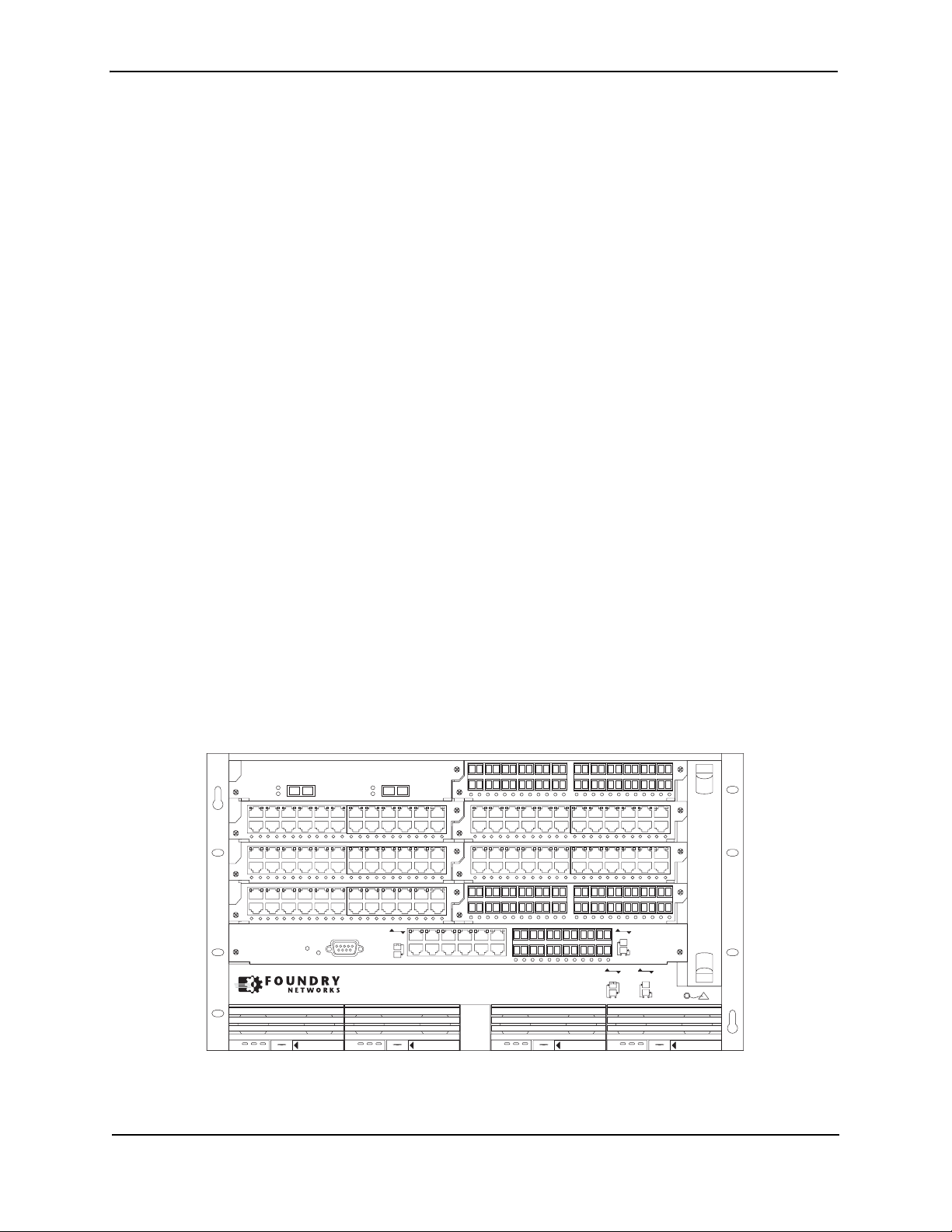
FSX Chassis
The FSX chassis is 6 rack units (RUs) in height and consists of the following:
• One full slot for the management module
• Eight half slots for the interface modules
• Four slots for power supplies along the bottom of the card shelf. The power supply slots add an additional RU
to the height of the chassis.
Figure 2.1 shows the FSX chassis.
Figure 2.1 FSX Chassis
42XG
424C
424C
8X-12GM-4
12
Lnk
Act
Pwr
Console
Lnk
Act
Odd
Even
Lnk
424F
424C
424C424C
424F
FastIron SuperX
Odd
Even
Lnk
Odd
Odd
Even
Even
Lnk
424F
424C
POE
Lnk
DC OK ALMAC OK DC OK ALMAC OK DC OK ALMAC OK DC OK ALMAC OK
SYSEJECTSYSEJECTSYSEJECTSYSEJECT
Upon shipment from the factory, the following components are installed in the FSX chassis:
• A slot panel in each interface module slot and power supply slot that does not currently have a module or
2 - 4 © 2008 Foundry Networks, Inc. December 2008
Product Overview
power supply installed in it. The slot panel ensures proper airflow within the chassis.
• One or two AC or DC power supplies
• A fan tray assembly which contains the cooling system for the chassis
In the FSX slots, you can install the following:
• One management module
• Up to eight interface modules
• Up to four AC and DC power supplies: two system (12-volt) power supplies and two POE (48- or 220-volt)
power supplies
Before installing any modules or power supplies, you must remove the slot panel.
CAUTION: If you do not install a module in a slot, you must keep the slot panel in place. If you run the chassis
with an uncovered slot, the system will overheat.
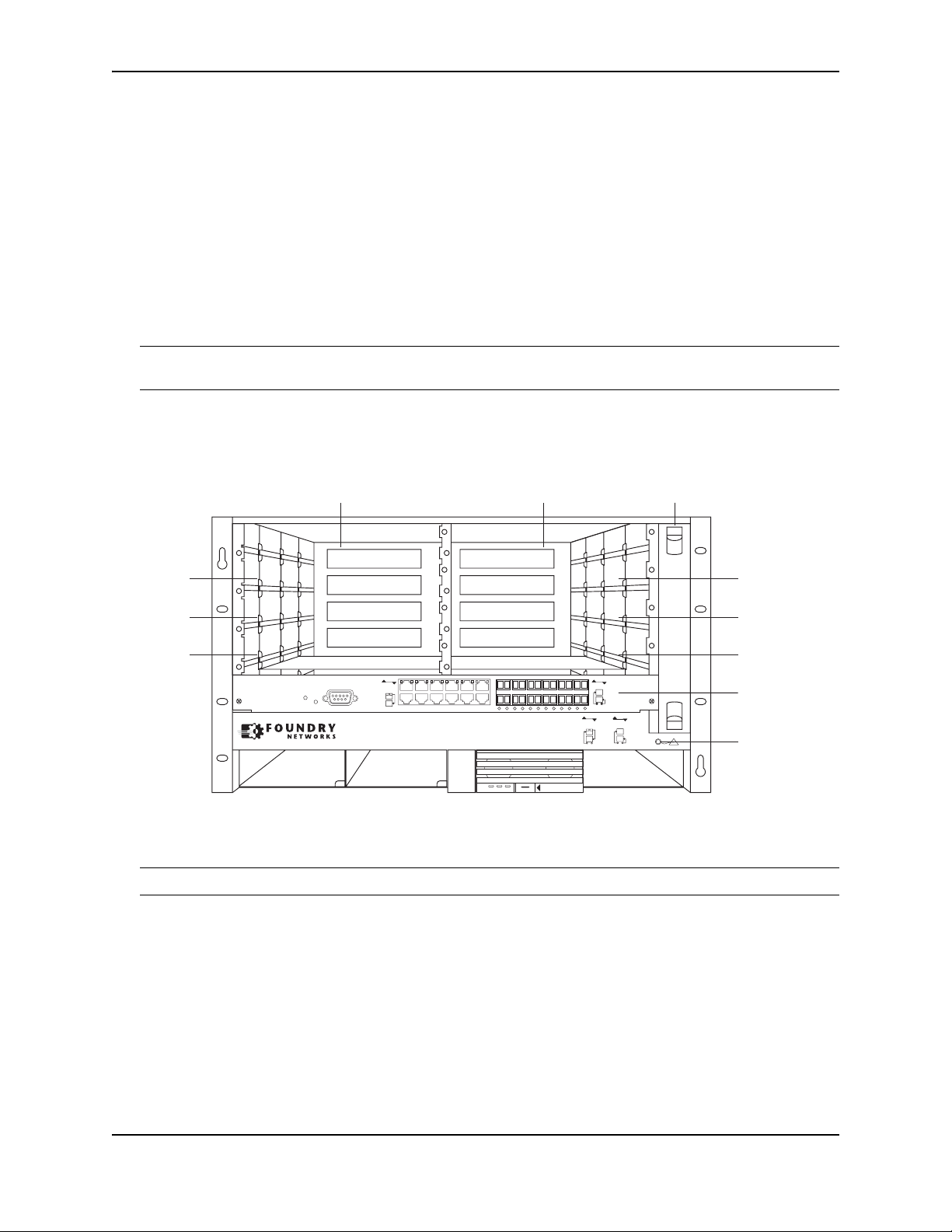
Figure 2.2 shows the FSX Chassis and the slots into which you can install the various modules and power
supplies.
Figure 2.2 FSX Chassis Slots
Slot 3
Slot 5
Slot 7
8X-12GM-4
Slot 1 Slot 2
Odd
Console
Pwr
Even
Lnk
FastIron SuperX
Odd
Even
Lnk
Odd
Even
Lnk
424F
424C
POE
DC OK ALMAC OK
SYSEJECT
FanTray
Slot 4
Slot 6
Slot 8
Slot 9
Odd
Even
Lnk
ESD
Connector
Figure 2.2 also shows an electrostatic discharge (ESD) connector, into which you can plug an ESD wrist strap to
ground yourself while handling and installing modules.
WARNING: For safety reasons, the ESD wrist strap should contain a series 1 meg ohm resistor.
FSX 800 Chassis
The FSX 800 chassis is 6 rack units in height and consists of the following:
• Two half slots for the management modules
• Two half slots for the switch fabric modules
• Eight half slots for the interface modules
• Four slots for power supplies along the bottom of the card shelf. The power supply slots add an additional
rack unit (RU) to the height of the chassis.
December 2008 © 2008 Foundry Networks, Inc. 2 - 5
FastIron Hardware Installation Guide for the FSX, FSX 800, and FSX 1600
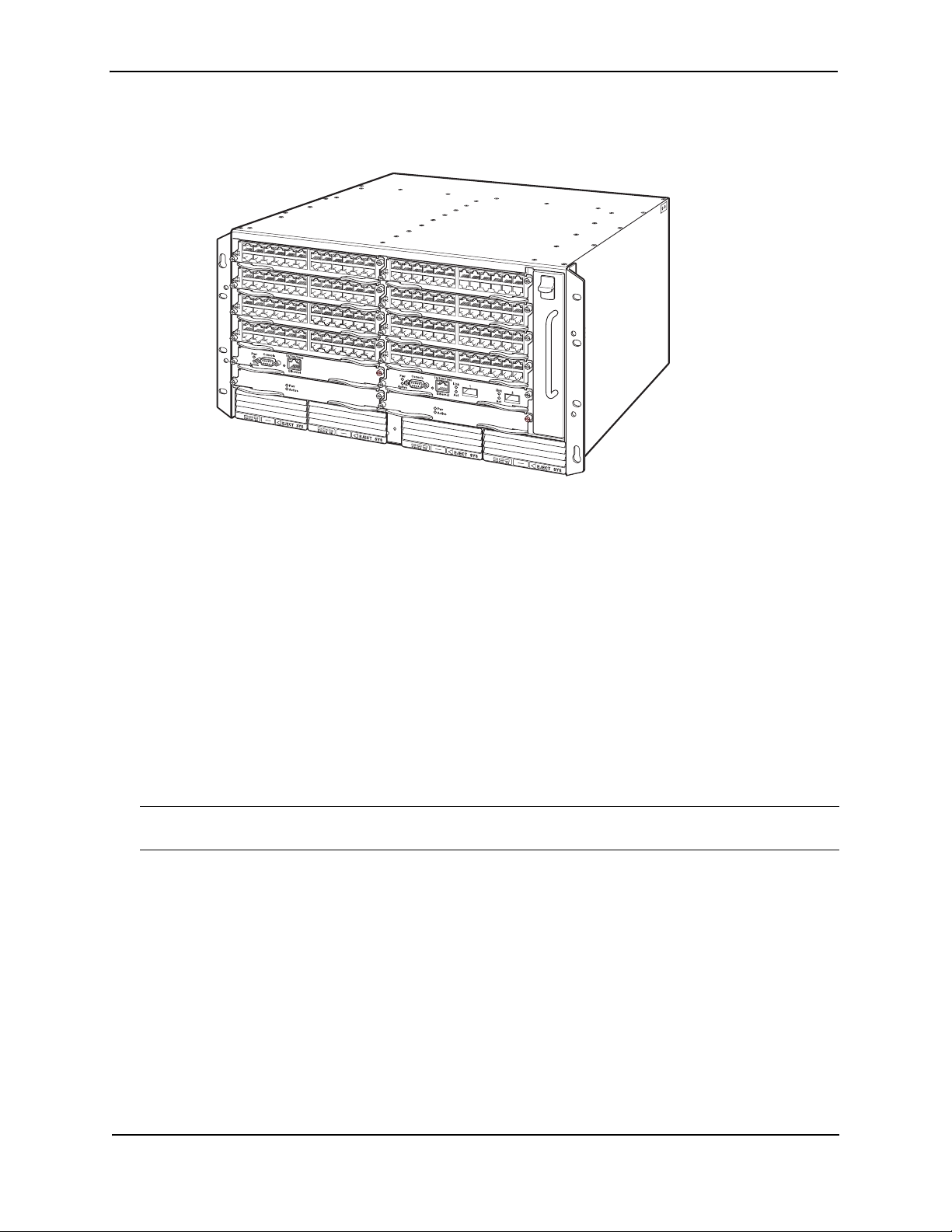
Figure 2.3 shows the FSX 800 chassis.
Figure 2.3 FSX 800 Chassis
The FSX 800 chassis ships from the factory with the following components installed:
• Two switch fabric modules
• A slot panel in each interface module slot and power supply slot that does not currently have a module or
power supply installed in it. The slot panel ensures proper airflow within the chassis.
• One AC power supply
• A fan tray assembly which contains the cooling system for the chassis
In the FSX 800 slots, you can install the following:
• Up to two management modules
• Up to eight interface modules
• Up to four AC and DC power supplies: two system (12-volt) power supplies and two POE (48- or 220-volt)
power supplies
Before installing any modules or power supplies, you must remove the slot panel.
CAUTION: If you do not install a module in a slot, you must keep the slot panel in place. If you run the chassis
with an uncovered slot, the system will overheat.
2 - 6 © 2008 Foundry Networks, Inc. December 2008
Product Overview
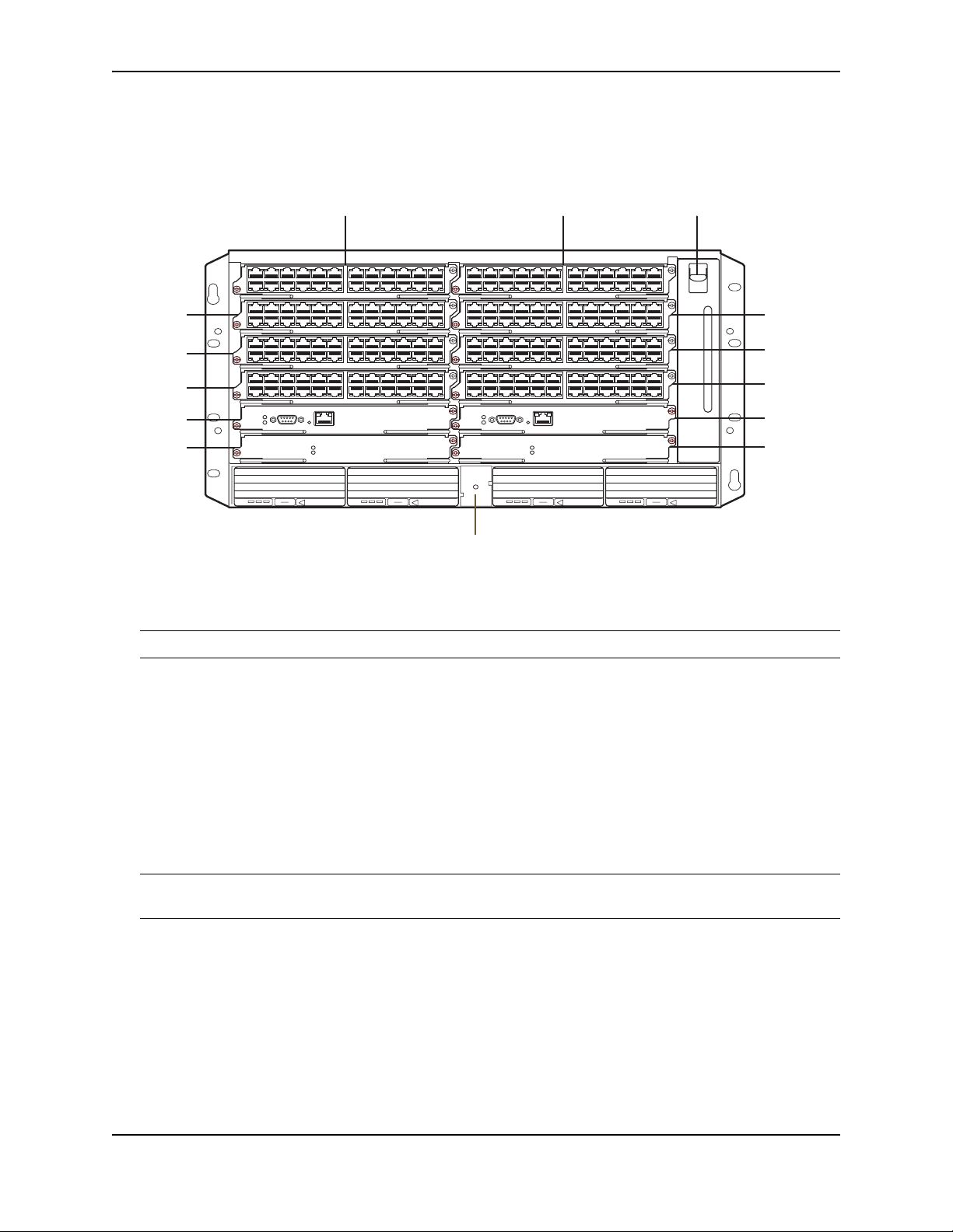
Figure 2.4 shows the FSX 800 Chassis and the slots into which you can install the various modules and power
supplies.
Figure 2.4 FSX 800 Chassis Slots
Slot 1 Slot 2 Fan Tray
EJECT POE
F1
424C
F1
424C
F1
424C
F1
424C
10/100/1000
Console
Pwr
Active
Ethernet
Pwr
Active
Slot 6
Slot 8
Slot 10
Switch
Fabric
Slot 2
AC OKDC OK ALM
EJECT SYS
AC OKDC OK ALM
EJECT SYS
F1
424C
F1
Slot 3 Slot 4
Slot 5
Slot 7
Slot 9
Switch
424C
F1
424C
F1
424C
10/100/1000
Console
Pwr
Active
Ethernet
Pwr
Active
Fabric
Slot 1
AC OKDC OK ALM
EJECT POE
AC OKDC OK ALM
ESD Connector
Figure 2.4 also shows an electrostatic discharge (ESD) connector, into which you can plug an ESD wrist strap to
ground yourself while handling and installing modules.
WARNING: For safety reasons, the ESD wrist strap should contain a series 1 meg ohm resistor.
FSX 1600 Chassis
There are two versions of the FSX 1600 chassis:
• FSX 1600 – Part numbers for chassis and bundles begin with FI-SX-1600-xxx...
• FSX 1600 Acoustic Noise-Reduced (ANR) – An enhanced version of the FSX 1600 chassis, part numbers for
chassis and bundles begin with FI-SX-1600-ANR-xxx...
This section describes the similarities between these models. For details about how these models differ, see “FSX
1600-ANR Chassis” on page 2-9.
NOTE: Except where explicitly noted throughout this manual, the FSX 1600 and FSX 1600-ANR chassis are
collectively referred to as the FSX 1600 chassis.
The FSX 1600 and FSX 1600-ANR chassis are 14 rack units in height and consist of the following:
• Two half slots for the management modules
• Two half slots for the switch fabric modules
• Sixteen half slots for the interface modules
• Eight slots for power supplies along the bottom of the card shelf.
December 2008 © 2008 Foundry Networks, Inc. 2 - 7
FastIron Hardware Installation Guide for the FSX, FSX 800, and FSX 1600
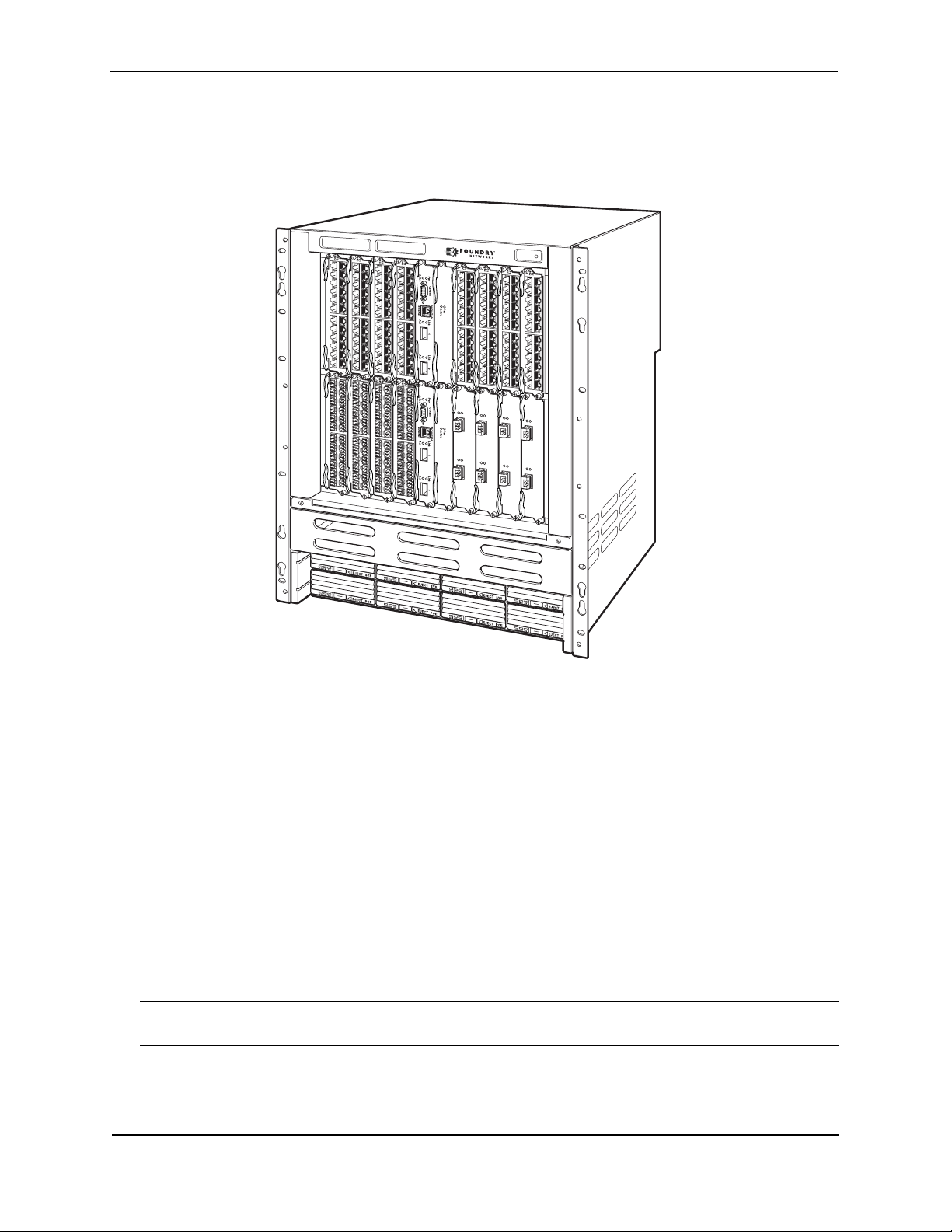
Figure 2.5 shows the front of the FSX 1600 chassis. The front of the FSX 1600-ANR chassis is identical to the
front of the FSX 1600 chassis.
Figure 2.5 FSX 1600 Chassis Front
Upon shipment from the factory, the following components are installed in the chassis:
• Two switch fabric modules
• A slot panel in each interface module slot and power supply slot that does not currently have a module or
power supply installed in it. The slot panel ensures proper airflow within the chassis.
• Two AC power supplies
• A fan tray assembly which contains the cooling system for the chassis
• The FSX 1600-ANR chassis has an ANR kit attached to the rear of the chassis
In the chassis slots, you can install the following:
• Up to two management modules
• Up to 16 interface modules
• Up to eight AC or DC power supplies (four system (SYS) power supplies and four POE power supplies)
Before installing any modules or power supplies, you must remove the slot panel.
CAUTION: If you do not install a module in a slot, you must keep the slot panel in place. If you run the chassis
with an uncovered slot, the system will overheat.
2 - 8 © 2008 Foundry Networks, Inc. December 2008
Product Overview
r
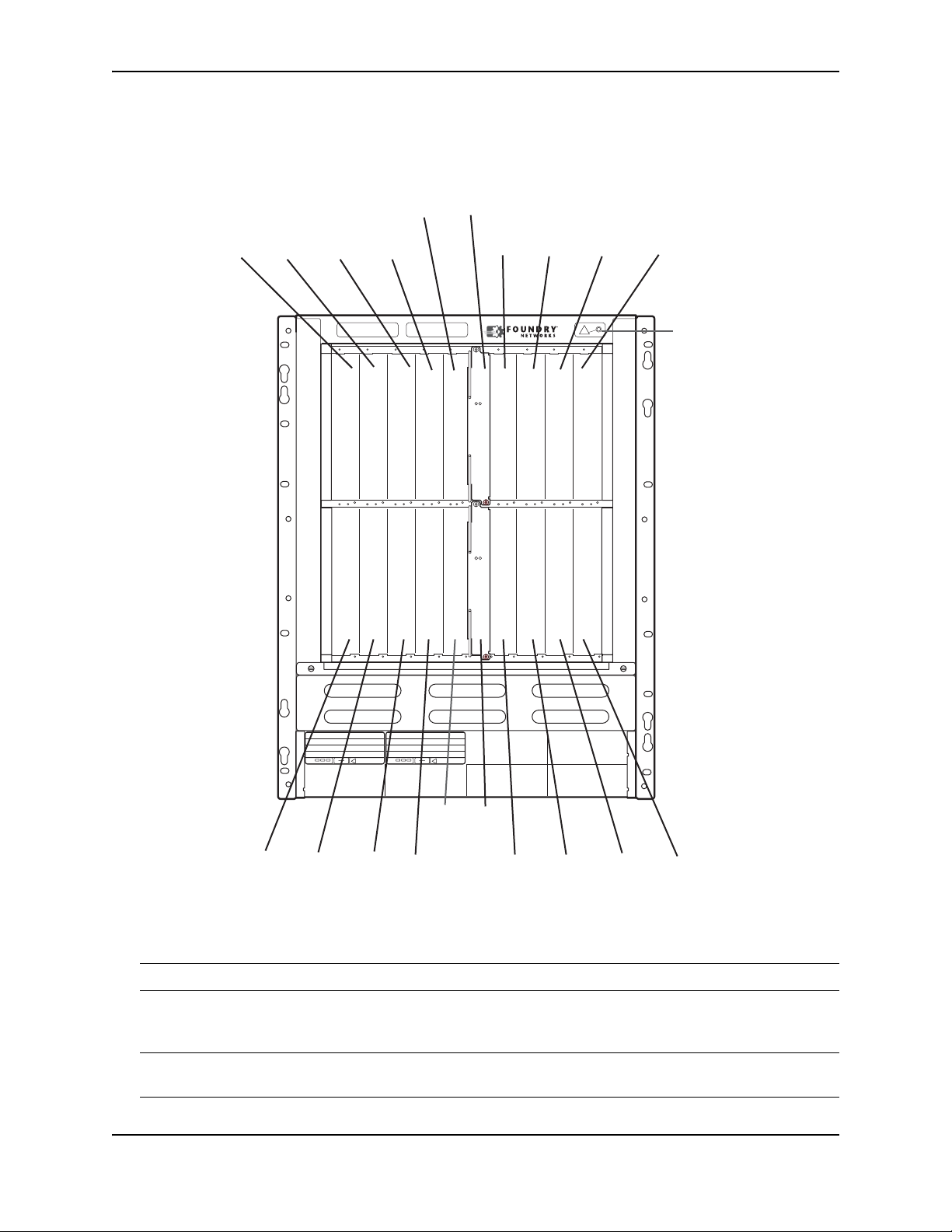
Figure 2.6 shows the chassis slots into which you can install the various modules and power supplies.
Figure 2.6 FSX 1600 Chassis Slots
Switch Fabric
Mgmt
Slot 1
Slot 9
Interface
Slot 1
Interface
Slot 3
Interface
Slot 5
Interface
Slot 7
Interface
Slot 11
Active
Pwr
Interface
Slot 13
Interface
Slot 15
Interface
Slot 17
ESD
Connecto
Active
Pwr
AC OKDC OK ALM
EJECT SYS
AC OKDC OK ALM
EJECT SYS
Mgmt
Slot 10
Switch
Fabric
Slot 2
Interface
Slot 2
Interface
Slot 4
Interface
Slot 6
Interface
Slot 8
Interface
Slot 12
Interface
Slot 14
Interface
Slot 16
Interface
Slot 18
Figure 2.6 also shows an electrostatic discharge (ESD) connector, into which you can plug an ESD wrist strap to
ground yourself while handling and installing modules.
WARNING: For safety reasons, the ESD wrist strap should contain a series 1 meg ohm resistor.
FSX 1600-ANR Chassis
NOTE: This section describes the differences between the FSX 1600-ANR chassis and the FSX 1600 chassis.
For details about the similarities, see “FSX 1600-ANR Chassis” on page 2-9.
December 2008 © 2008 Foundry Networks, Inc. 2 - 9
FastIron Hardware Installation Guide for the FSX, FSX 800, and FSX 1600
The FSX 1600 Acoustic Noise-Reduced (ANR) chassis is an enhanced version of the FSX 1600 chassis. Part
numbers for the FSX 1600-ANR chassis and bundles begin with FI-SX-1600-ANR-xxx...
NOTE: Except where explicitly noted throughout this manual, the FSX 1600 and FSX 1600-ANR chassis are
collectively referred to as the FSX 1600 chassis.
NOTE: The FSX 1600-ANR chassis is available through new orders beginning with software release FSX
04.3.00. If you want to upgrade your existing FSX 1600 to an FSX 1600-ANR chassis, you must ship it to to
Foundry Networks, where an ANR kit will be installed, then the chassis will be shipped back to you. For more
information, contact Foundry Networks.
Compared to the FSX 1600, the FSX 1600-ANR has improved, redirected airflow, better thermal dissipation, and
reduced acoustic noise. The front of the FSX 1600-ANR chassis is identical to the FSX 1600 and both chassis
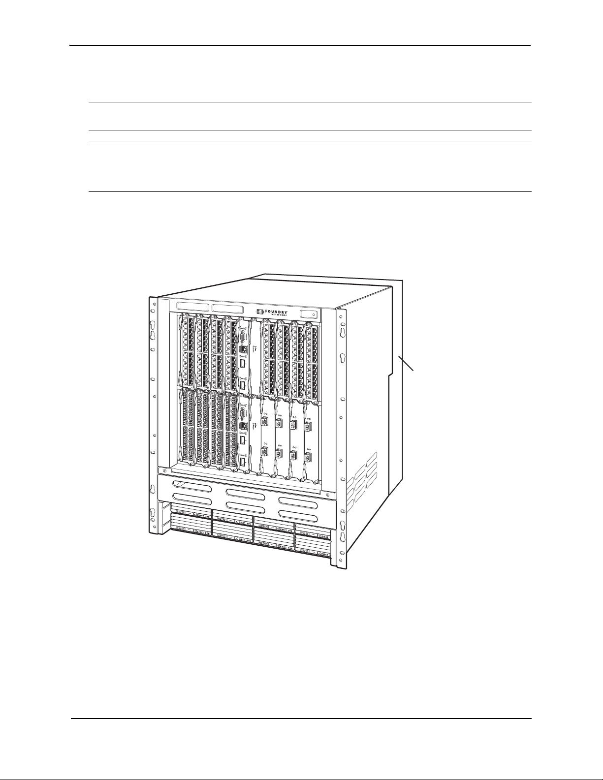
use the same switch fabric, management and interface modules, and power supplies. Figure 2.7 shows the front
of the chassis, including a partial view of the ANR kit, which is behind the chassis.
Figure 2.7 FSX 1600-ANR Chassis Front
ANR Kit
on rear
of chassis
The back of the FSX 1600-ANR chassis differs from the FSX 1600 chassis in that the FSX 1600-ANR has an extra
sheet metal assembly (ANR kit) and different fan modules. The ANR kit protrudes from the rear of the chassis,
making the depth of the FSX 1600-ANR chassis four inches longer than the FSX 1600 chassis. Figure 2.8 shows
a side-by-side comparison of the FSX 1600 and the FSX 1600-ANR.
2 - 10 © 2008 Foundry Networks, Inc. December 2008
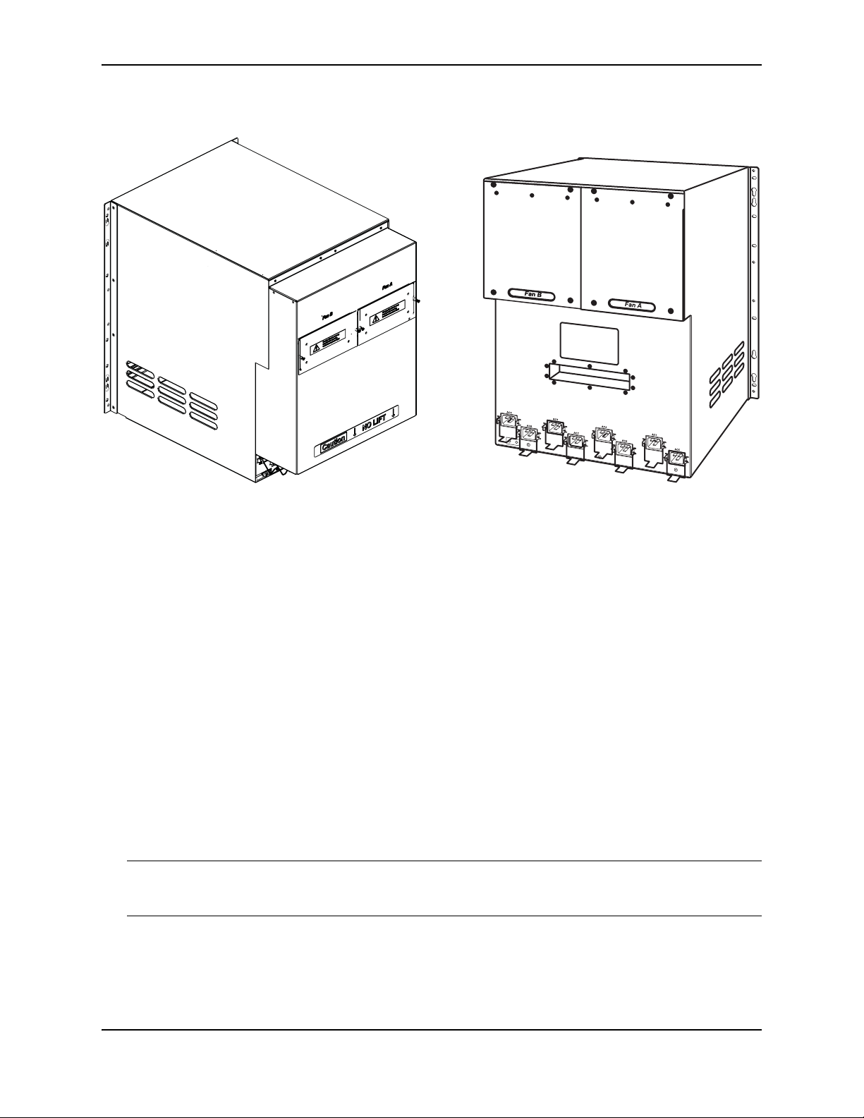
Figure 2.8 Side-by-Side Comparison of the FSX 1600-ANR and FSX 1600 Chassis
Product Overview
FSX 1600-ANR Chassis Rear View FSX 1600 Chassis Rear View
The FSX 1600-ANR chassis was introduced with software release FSX 04.3.00. The ANR chassis supports the
same software release versions supported on the FSX 1600. If your ANR chassis is running software release
04.3.00 or later, the display output for the CLI commands show chassis and show version identify the chassis as
an ANR chassis. Also, the SNMP object snChasType returns the chassis type ANR-Chassis. For details about
the show chassis command, see “Displaying Chassis Status and Temperature Readings” on page 5-1. For
details about the show version command, refer to the section “Viewing System Information” in the Foundry
FastIron Configuration Guide.
Management Modules
This section describes the management modules for the FastIron X Series chassis devices.
• The FSX chassis requires one management module. The management module occupies one full slot.
• The FSX 800 and FSX 1600 chassis each require one management module and optionally support two
management modules for 100% redundancy. Each management module occupies one half slot.
FSX Management Modules
The FSX management module has a built-in switch fabric module and comes with 12 combination GbE Copper
and Fiber ports.
NOTE: The FSX management module is dedicated, which means that it can be installed in the FSX chassis only.
If you attempt to install the FSX management module in the FSX 800, FSX 1600, or other Foundry chassis, the
chassis and module will not function properly.
December 2008 © 2008 Foundry Networks, Inc. 2 - 11

FastIron Hardware Installation Guide for the FSX, FSX 800, and FSX 1600
Table 2.3 lists the management modules supported on the FSX chassis.
Table 2.3: FSX Management Modules
NOTE:
Part Number Microprocessor
Speed (MHz)
IPv4 Management Modules
SX-FI12GM-4 400 256
SX-FI12GM-4-PREM
SX-FI12GM2-4 466 512
SX-FI12GM2-4-PREM
IPv6 Management Modules
SX-FI12GM-6 400 256
SX-FI12GM-6-PREM
SX-FI12GM-6-PREM6
SX-FI12GM2-6 466 512
SX-FI12GM2-6-PREM
SX-FI12GM2-6-PREM6
MB SDRAM
• The management modules with 512 MB SDRAM enable support for larger routing tables (1,000,000 BGP
routes) with the full Layer 3 code.
• The IPv6 management modules ending with -PREM were introduced in software release 04.0.00. These
modules provide additional support for full Layer 3 IPv4 routing protocols.
• The IPv6 management modules ending with -PREM6 were introduced in software release 04.1.00.
These modules provide additional support for full Layer 3 IPv4 and IPv6 routing protocols. The -PREM6
management modules require software release 04.1.00 or higher to run the supported IPv6 routing
protocols and features.
The FSX management module does the following:
• Controls the FSX hardware components
• Houses and controls the switch fabric module
• Runs the networking protocols
• Provides the real time operating system
The management module is located in slot 9, just above the power supply slots (see Figure 2.2).
2 - 12 © 2008 Foundry Networks, Inc. December 2008

Figure 2.9 shows the management module’s front panel.
Figure 2.9 FSX Management Module Front Panel
Product Overview
8X-12GM-4
Odd
Console
Pwr
Even
Lnk
10/100/1000
Ethernet Copper
Gigabit
Ethernet Fiber
Odd
Even
Lnk
The front panel includes the following control features:
• A Console port
• 12 combination GbE Copper and Fiber ports
• 25 LEDs – One LED for power, 12 LEDs for the copper ports, and 12 LEDs for the fiber ports
• A recessed reset button
Gigabit Ethernet Ports on the FSX Management Module
The FSX management module’s front panel includes 12 combination copper and fiber Gigabit Ethernet ports.
• RJ-45 copper interfaces for 1000Base-T, Cat5 copper cabling – The copper ports support automatic MDI/
MDIX detection, and use auto-sensing and auto-negotiating to determine the speed (10, 100, or 1000 Mbps)
and duplex mode (full-duplex or half-duplex) of the port at the other end of the link, and adjust the port
accordingly. Note that ports operating at 1000 Mbps operate in the full-duplex mode only and cannot be
modified.
• Mini-GBIC slots for the types of fiber cabling listed in Table 8.9 on page 8-12.
NOTE: The Management Module does not support copper mini-GBICs.
NOTE: Some older SFP modules (mini-GBICs for Gigabit Ethernet ports) have latching mechanisms which are
larger than the newer parts. These latches could interfere with one another when inserted side by side into a
module. Avoid using these mini-GBICs side by side in the same module. These older modules are identified by the
number PL-XPL-00-S13-22 or PL-XPL-00-L13-23 above the Serial Number. All newer mini-GBICs do not have
this limitation.
The Gigabit Ethernet fiber ports operate at a fixed speed of 1000 Mbps (they do not support 10 Mbps or 100 Mbps
connections), and use auto-negotiation to automatically configure the highest performance mode of interoperation with the connected device.
One port out of each pair of copper and fiber ports can be active at a time. For example, you can use either
copper port 2 or fiber port 2, but not both at the same time. You can use a combination of fiber and copper ports
or all copper or all fiber ports, as needed.
If you attach both the copper and fiber connectors for a port to the network, the fiber connector takes precedence
over the copper connector. These ports support true media automatic detection, meaning the device selects the
fiber or copper connector based on link availability. If a fiber link cannot be established, the device selects the
copper media.
Typical uses of these ports include but are not limited to the following:
• Connecting a PC through which you can access the system directly or through a Telnet connection and
configure, monitor, and manage the FSX system.
• Connecting a Gigabit Ethernet switch, which will provide connectivity to your existing management network.
You can then access the FSX system and configure, monitor, and manage the system from a management
station.
December 2008 © 2008 Foundry Networks, Inc. 2 - 13
FastIron Hardware Installation Guide for the FSX, FSX 800, and FSX 1600
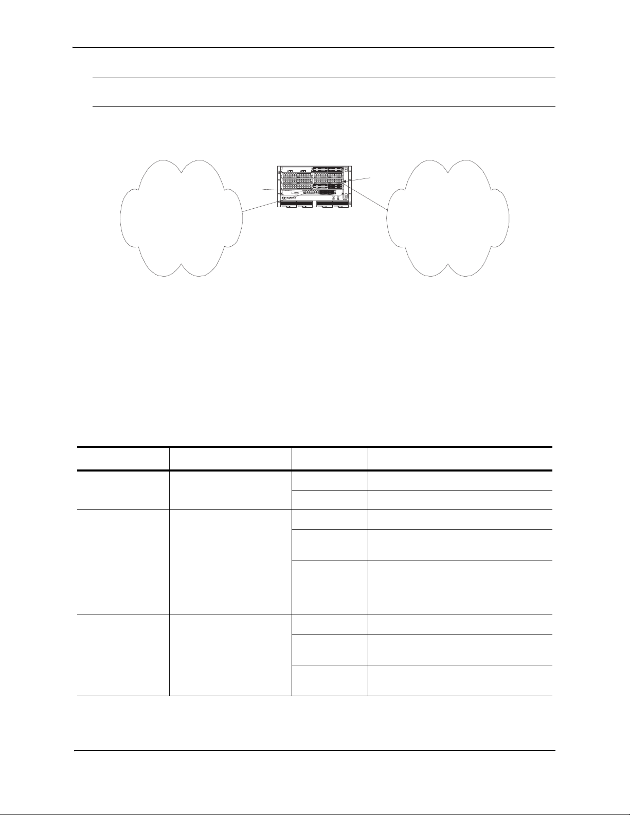
NOTE: The existing management networks into which you can connect the Gigabit Ethernet ports must be
separate and isolated from the network over which user packets are switched and routed as shown in Figure 2.10.
Figure 2.10 Separate Management and Switching/Routing Networks
FastIron SuperX
Interface
Management
port
d
FastIron SuperX
Management
Network
LEDs on the FSX Management Module
The FSX management module provides status information using the LEDs listed in Table 2.4. The location of the
LEDs is as follows:
• The fiber connectors use the LEDs located beneath the mini-GBIC slots.
• The copper connectors use square LEDs located in the upper right and left corners of the upper Gigabit
copper connectors. The LED on the left side is for the upper copper connector. The LED on the right side is
for the lower copper connector.
Table 2.4 describes the LEDs on the FSX management module.
module port
SYSEJECTSYSEJECTSYSEJECTSYSEJECT
Switching and Routing
Network
Table 2.4: FSX Management Module LEDs
LED Description and Position State Meaning
Pwr Round LED located to the
On (Green) The module is receiving power.
left of the console port
Off The module is not receiving power.
10/100/1000 Mbps
Copper Ports (
Square LED located on
upper left corner of upper
copper connector for upper
copper connector
Square LED located on
upper right corner of upper
On (Green) A link is established with the remote port.
Blinking The port is transmitting and receiving
traffic.
Off A link is not established with the remote
port.
copper connector for lower
copper connector
1000 Mbps Fiber
Por ts
Round LED located
beneath the fiber
connectors
On (Green) A link is established with the remote port.
Blinking The port is transmitting and receiving
packets.
Off A link is not established with the remote
port.
2 - 14 © 2008 Foundry Networks, Inc. December 2008

Product Overview
Built-in Switch Fabric Module
The switch fabric module switches user packets from one interface module installed in the chassis to another. On
the FSX, the switch fabric module is built into the management module.
Console Port
The Console port on the management module is a standard DB-9 serial connector through which you can attach a
PC or terminal to configure the system using the command line interface (CLI).
The Console port interfaces the control plane only and not the data plane.
Reset Button
The reset button on the management module allows you to restart the system. The reset button is recessed to
prevent it from being pushed accidentally.
The reset button is located next to the console port on the management module.
FSX 800 and FSX 1600 Management Modules
The management modules for the FSX 800 and FSX 1600 are interchangeable between devices. Standard
management modules provide Layer 2 and base Layer 3 functionality only. Premium management modules
support full Layer 3 functionality.
NOTE:
• The FSX 800 and FSX 1600 management modules are dedicated, which means that you must install them in
the FSX 800 or FSX 1600 chassis only. If you attempt to install these management modules in the FSX or
other Foundry chassis, the chassis and modules will not function properly.
• You cannot intermix different management modules in the same FSX 800 or FSX 1600 chassis. The
management modules must be of like-kind.
• You cannot intermix IPv6 and IPv4 modules in the same FSX 800 or FSX 1600 chassis.
Table 2.5 lists the management modules for the FSX 800 and FSX 1600.
Table 2.5: FSX 800 and FSX 1600 Management Modules
Part Number Description Microprocessor
Speed (MHz)
IPv4 Management Modules
SX-FIZMR no ports 667 512
SX-FIZMR-PREM
SX-FI2XGMR4 two 10-GbE ports 667 512
SX-FI2XGMR4-PREM
SX-FI8GMR4 eight GbE ports (four
copper and four fiber
SX-FI8GMR4-PREM
IPv6 Management Modules
SX-FIZMR-6-PREM no ports 667 512
SX-FIZMR-6-PREM6
667 512
MB SDRAM
December 2008 © 2008 Foundry Networks, Inc. 2 - 15
FastIron Hardware Installation Guide for the FSX, FSX 800, and FSX 1600
Table 2.5: FSX 800 and FSX 1600 Management Modules
Part Number Description Microprocessor
MB SDRAM
Speed (MHz)
SX-FI2XGMR6 two 10-GbE ports 667 512
SX-FI2XGMR6-PREM
SX-FI2XGMR6-PREM6
SX-FI8GMR6 eight GbE ports (four
SX-FI8GMR6-PREM
copper and four fiber)
667 512
SX-FI8GMR6-PREM6
NOTE:
• 512 MB SDRAM enables support for large routing tables (1,000,000 BGP routes) with the full Layer 3
code.
• The SX-FI8GMR4 and SX-FI8GMR4-PREM management modules were added in release FSX 04.3.00.
• The IPv6 management modules ending with -PREM were introduced in software release 04.0.00. These
modules provide additional support for full Layer 3 IPv4 routing protocols.
• The IPv6 management modules ending with -PREM6 were introduced in software release 04.1.00.
These modules provide additional support for full Layer 3 IPv4 and IPv6 routing protocols. The -PREM6
management modules require software release 04.1.00 or higher to run the supported IPv6 routing
protocols and features.
The FSX 800 and FSX 1600 management modules perform the following tasks:
• Control the hardware components
• Control the separate switch fabric modules
• Run the networking protocols
• Provide the real time operating system
FSX 800 management modules are located in slots 9 and 10, just above the switch module slots (see Figure 2.4).
FSX 1600 management modules are located in slots 9 and 10 along the center of the chassis (see Figure 2.6).
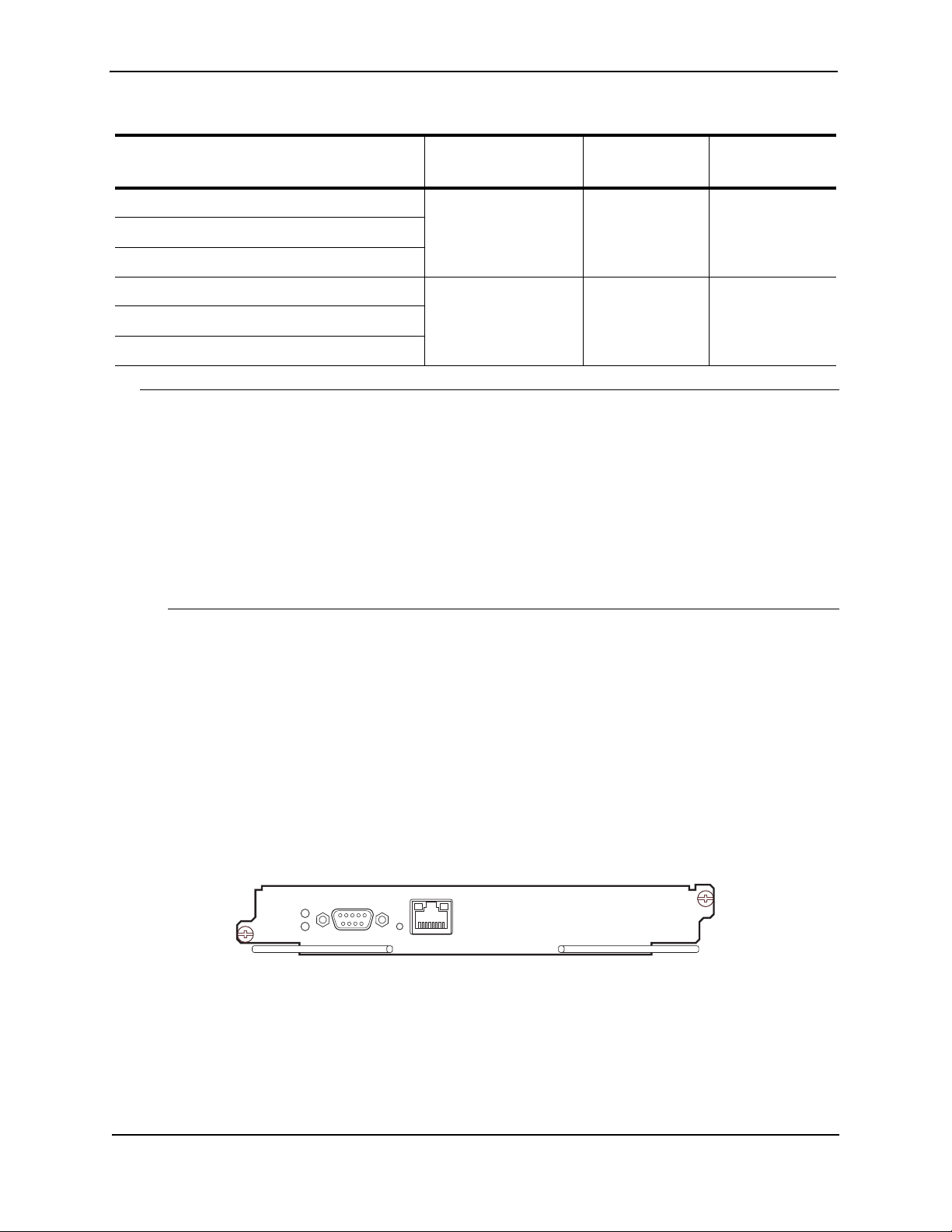
Figure 2.11 shows the front panel of the IPv4 and IPv6 management modules with no ports.
Figure 2.11 FSX 800 and FSX 1600 Management Module with No Ports
Pwr
Active
Console
10/100/1000
Ethernet
2 - 16 © 2008 Foundry Networks, Inc. December 2008
Product Overview
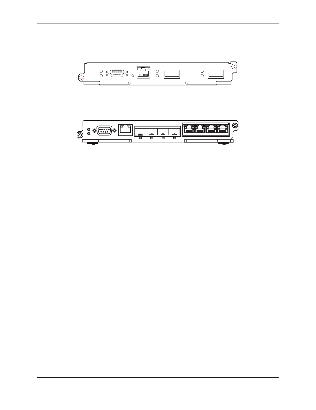
Figure 2.12 shows the front panel of the IPv4 and IPv6 management modules with two 10-GbE ports.
Figure 2.12 FSX 800 and FSX 1600 Management Module with two 10-GbE ports
Pwr
Active
Console
10/100/1000
Ethernet
Link
Act
12
Link
Act
Figure 2.13 shows the front panel of the IPv4 and IPv6 management modules with eight GbE ports.
Figure 2.13 FSX 800 and FSX 1600 IPv4 and IPv6 8-port Management Module
Pwr
Active
Console
10/100/1000
Ethernet
1 2 3 4
5 6 7 8
The front panel on the management modules include the following control features:
• A Console port and 10/100/1000 RJ-45 copper port allow you to access the system’s CLI directly from a PC
or terminal or via a Telnet connection to the PC or terminal.
• Depending on the type of management modules installed in the device, the management modules have the
following ports:
• no 10-GbE fiber ports
• two 10-GbE fiber ports
• eight GbE copper and fiber ports (four copper and four fiber)
• LEDs for power and active/standby status
• Four LEDs for the two 10-GbE fiber ports (2-port 10-GbE modules only)
• A recessed reset button
10/100/1000 GbE Copper Port on the FSX 800 and FSX 1600 Management Modules
The 10/100/1000 RJ-45 copper port on the management module enables you to attach a PC or terminal. From
this Ethernet port, you can access the system’s CLI or Web management interface directly from the PC or terminal
or via a Telnet connection to the PC or terminal.
10-GbE Ports on the FSX 800 and FSX 1600 2-port 10-GbE Management Modules
The FSX 800 and FSX 1600 2-port 10-GbE management modules come with two 10-GbE fiber ports through
which you can connect your device to other network devices at a speed of 10 Gigabits per second.
The 10-GbE ports have optical interfaces with LC connectors for 10-Gigabit Small Form Factor Pluggable (XFP)
MSA-compliant transceivers. The transceivers support the fiber optic cabling for LAN PHY listed in Table 8.9 on
page 8-12.
Gigabit Ethernet Ports on the FSX 800 and FSX 1600 8-port Management Modules
The FSX 800 and FSX 1600 8-port management modules come with eight copper and fiber Gigabit Ethernet ports
(four copper and four fiber), through which you can connect your device to other network devices at a speed of 1
Gigabit per second. These ports are not combo ports and can be used simultaneously.
• The copper ports have RJ-45 copper interfaces for 1000Base-T, Cat5 copper cabling – The copper ports
support automatic MDI/MDIX detection, and use auto-sensing and auto-negotiating to determine the speed
(10, 100, or 1000 Mbps) and duplex mode (full-duplex or half-duplex) of the port at the other end of the link,
and adjust the port accordingly. Note that ports operating at 1000 Mbps operate in the full-duplex mode only
and cannot be modified.
December 2008 © 2008 Foundry Networks, Inc. 2 - 17

FastIron Hardware Installation Guide for the FSX, FSX 800, and FSX 1600
• The fiber ports have mini-GBIC slots for the types of fiber cabling listed in Table 8.9 on page 8-12.
NOTE: The Management Module does not support copper mini-GBICs.
NOTE: Some older SFP modules (mini-GBICs for Gigabit Ethernet ports) have latching mechanisms which are
larger than the newer parts. These latches could interfere with one another when inserted side by side into a
module. Avoid using these mini-GBICs side by side in the same module. These older modules are identified by the
number PL-XPL-00-S13-22 or PL-XPL-00-L13-23 above the Serial Number. All newer mini-GBICs do not have
this limitation.
The Gigabit Ethernet fiber ports operate at a fixed speed of 1000 Mbps (they do not support 10 Mbps or 100 Mbps
connections), and use auto-negotiation to automatically configure the highest performance mode of interoperation with the connected device.
LEDs on the FSX 800 and FSX 1600 Management Modules
The management modules provide status information using the LEDs listed in Table 2.6.
Table 2.6: FSX 800 and FSX 1600 Management Module LEDs
LED Description and Position State Meaning
Pwr Round LED located to the left
of the console port
Active Round LED located to the left
of the console port
10/100/1000 Copper Port LEDs
Lnk Left-most LED above the port On The port is connected.
Act Right-most LED above the
port.
1000 Mbps Fiber Port LEDs
Lnk/Act Round LED located beneath
the fiber connectors
On (Green) The module is receiving power.
Off The module is not receiving power.
On (Green) The module is the active management
module.
Off The module is not the active management
module.
Off No port connection exists.
On or Blinking The port is transmitting and receiving
traffic.
Off The port is not transmitting or receiving
traffic.
On (Green) A link is established with the remote port.
Blinking The port is transmitting and receiving
packets.
Off A link is not established with the remote
port.
10-GbE Port LEDs
Lnk Top-most LED to the left of the
port.
2 - 18 © 2008 Foundry Networks, Inc. December 2008
On Fiber port is connected.
Off No fiber port connection exists.
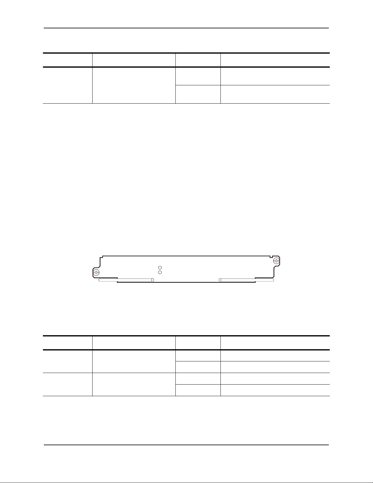
Table 2.6: FSX 800 and FSX 1600 Management Module LEDs (Continued)
LED Description and Position State Meaning
Product Overview
Act Bottom-most LED to the left of
the port.
Console Port
The Console port on the management module is a standard DB-9 serial connector through which you can attach a
PC or terminal to configure the system using the command line interface (CLI).
The Console port interfaces the control plane only and not the data plane.
Reset Button
The reset button on the management module allows you to restart the system. The reset button is recessed to
prevent it from being pushed accidentally.
The reset button is located next to the console port on the management module.
On or Blinking The port is transmitting and receiving
traffic.
Off The port is not transmitting or receiving
traffic.
Switch Fabric Modules (FSX 800 and FSX 1600 only)
The switch fabric modules switch user packets from one interface module installed in the chassis to another.
Unlike the FSX, which has a switch fabric module built into the management module, the switch fabric modules in
the FSX 800 and FSX 1600 chassis are separate from the management modules and are physically located next
to the management modules.
Figure 2.14 shows the FSX 800 and FSX 1600 switch fabric module.
Figure 2.14 FSX 800 and FSX 1600 Switch Fabric Module
Pwr
Active
LEDs on the Switch Fabric Module
The front panel provides status information using the LEDs listed in Table 2.7.
Table 2.7: Switch Fabric Module LEDs
LED Description and Position State Meaning
Pwr Top-most LED On (Green) The module is receiving power.
Off The module is not receiving power.
Active Bottom-most LED On (Green) The module is functioning properly.
Off The module is not functioning properly.
Interface Modules
This section describes the Interface modules for the FastIron X Series chassis devices.
• In the FSX chassis, you can install up to eight Interface modules in the slots shown in Figure 2.2 on page 2-5.
December 2008 © 2008 Foundry Networks, Inc. 2 - 19

FastIron Hardware Installation Guide for the FSX, FSX 800, and FSX 1600
• In the FSX 800 chassis, you can install up to eight Interface modules in the slots shown in Figure 2.4 on
page 2-7.
• In the FSX 1600 chassis, you can install up to 16 interface modules in the slots shown in Figure 2.6 on
page 2-9.
NOTE: You cannot mix IPv4 and IPv6 modules together in the same chassis.
Table 2.8 lists the supported Interface modules for each FastIron X Series chassis type.
Table 2.8: Interface Modules
Interface Module Part Number FSX FSX 800 FSX 1600
IPv4 Interface Modules
24-port Gigabit Ethernet Fiber (1000
Mbps only)
24-port Gigabit Ethernet copper without
POE
24-port Gigabit Ethernet copper with POE SX-FI424P 02.2.00 and
SX-FI424F 02.1.00 and
later
SX-FI424C 02.2.00 and
later
XX
XX
XX
later
24-port 100/1000 Hybrid Fiber SX-FI424HF 02.4.00 and
XX
later
2-port 10-Gigabit Ethernet LAN module SX-FI42XG X X X
2-port 10-Gigabit Ethernet LAN/WAN
SX-FI42XGW X X X
module
1
IPv6 Interface Modules
24-port Gigabit Ethernet copper without
SX-FI624C X X X
POE
24-port Gigabit Ethernet copper with POE SX-FI624P X X X
24-port 100/1000 Hybrid Fiber SX-FI624HF X X X
2-port 10-Gigabit Ethernet LAN module SX-FI62XG X X X
1. IPv6 Interface Modules were introduced in software release FSX 04.0.00. For usage guidelines, see “IPv6
Hardware Support Guidelines” on page 2-3.
Hot Swap Support
• Starting with software release 02.2.01 for the FSX, the interface modules are hot swappable, which means
you can remove and replace them without powering down the system; however, you must issue the disable
module command before you remove the modules from the chassis.
• Prior to software release 03.2.00, all FSX 800 and FSX 1600 software releases support hot swap of the
interface modules, but the disable module command must be issued, before removing the modules from the
chassis.
• In FSX software release 03.2.00 and later, issuing the disable module command before removing the
module is no longer required on the FastIron SX 800 and FastIron SX 1600 chassis. This is referred to as
“Enhanced Hot Swap”.
2 - 20 © 2008 Foundry Networks, Inc. December 2008

Product Overview
CAUTION: It is recommended that modules be disabled through the CLI before removal from the
chassis. If the operator wishes to remove the module without first disabling the module, the
Enhanced Hot Swap capability in software Release 03.2.00 and later supports this procedure
for the FastIron SX 800 and FastIron SX 1600 chassis. Enhanced Hot Swap (that is, no CLI
disable) should be performed during a maintenance window. On rare occasions, an
Enhanced Hot Swap may result in a software reload of the system. The likelihood of this event
is very low.
It is important to wait a minimum of 10 seconds between the removal and insertion of a line
module. Re-insertion of a line module less than 10 seconds after the removal of a line module
may result in the line module not being properly recognized.
See “Replacing an Interface Module” on page 7-7 for instructions.
24-port Gigabit Ethernet Copper Interface Module
The 24-port Gigabit Ethernet Copper interface module has 24 10/100/1000 ports with RJ-45 connectors for Cat5
cabling. The copper ports support automatic MDI/MDIX detection, and use auto-sensing and auto-negotiating to
determine the speed (10, 100, or 1000 Mbps) and duplex mode (full-duplex or half-duplex) of the port at the other
end of the link, and adjust the port accordingly. Note that ports operating at 1000 Mbps operate in the full-duplex
mode only and cannot be modified.
The 24-port Gigabit Ethernet Copper Interface module supports Power over Ethernet (POE). You can either order
the interface module with POE capability, or upgrade your existing 24-port Gigabit Ethernet Copper module by
installing a POE daughter card. To run POE on your system, you must also install at least one 48-volt power
supply.
NOTE: Instructions for installing a POE daughter card are provided in “Installing or Replacing a POE Daughter
Card” on page 7-12.
Figure 2.15 shows the front panel of the IPv4 24-port Gigabit Ethernet copper module.
Figure 2.15 IPv4 24-port Gigabit Ethernet Copper Module Front Panel
Port 1
424C
Port 2
Port 13
Port 24
Port 14 POE LEDs
Figure 2.16 shows the front panel of the IPv6 24-port Gigabit Ethernet copper module.
Figure 2.16 IPv6 24-port Gigabit Ethernet Copper Module Front Panel
Port 1
624C
Port 13
Port 24
Port 2
Port 14 POE LEDs
December 2008 © 2008 Foundry Networks, Inc. 2 - 21

FastIron Hardware Installation Guide for the FSX, FSX 800, and FSX 1600
The front panel includes the following control features:
• 24 10/100/1000 copper ports
• 24 LEDs for port status
• 24 LEDs for Power over Ethernet (POE) status
NOTE: The POE LEDs work only when POE is enabled on your device.
LEDs for 24-port Copper Module
The front panel of the 24-port Gigabit Ethernet copper module includes 24 LEDs that indicate the status of each
port, and 24 LEDs (on bottom) that indicate the status of POE.
NOTE: The POE LEDs work only when POE is enabled on your device.
The copper ports provide status information using the LEDs described in Table 2.9.
Table 2.9: LEDs for 10/100/1000 Copper Ports
LED Position State Meaning
Link/Activity Square LED located on
upper left corner of upper
copper connector for upper
copper connector
Square LED located on
upper right corner of upper
copper connector for lower
copper connector
POE (if
applicable)
Round LED located beneath
the copper ports
The first (left-most) LED is for
port 1, the second LED is for
port 2, the third LED is for
port 3, etc.
On (Green) A link is established with the remote port.
Blinking The port is transmitting and receiving traffic.
Off A link is not established with the remote port.
On (Green) The port is enabled, a power-consuming
device has been detected, and the module is
supplying power to the device.
Off The port is not providing in-line power.
24-port Gigabit Ethernet Fiber Interface Module
The 24-port Gigabit Ethernet Fiber interface module has 24 ports with connectors for mini-GBIC transceivers
(Small Form Factor Pluggable (SFP) Multisource Agreement (MSA)-compliant transceivers). The ports support
both fiber and copper mini-GBICs in any combination.
NOTE: The copper mini-GBICs are not supported on the FSX Management Module’s combination Gigabit
Ethernet Copper and Fiber ports.
The ports on the 24-port Gigabit Ethernet fiber module operate at a fixed speed of 1000 Mbps (they do not support
10 Mbps or 100 Mbps connections). In addition, the ports operate in full-duplex mode only, and use autonegotiation to automatically configure the highest performance mode of inter-operation with the connected device.
2 - 22 © 2008 Foundry Networks, Inc. December 2008

Product Overview
The mini-GBIC slots support the types of 1000Base fiber and copper cabling listed in “Network Interfaces” on
page 2-25.
NOTE: Some older SFP modules (mini-GBICs for Gigabit Ethernet ports) have latching mechanisms which are
larger than the newer parts. These latches could interfere with one another when inserted side by side into a
module. Avoid using these mini-GBICs side by side in the same module. These older modules are identified by the
number PL-XPL-00-S13-22 or PL-XPL-00-L13-23 above the Serial Number. All newer mini-GBICs do not have
this limitation.
Figure 2.17 shows the front panel of the IPv4 24-port Gigabit Ethernet fiber module.
Figure 2.17 IPv4 24-port Gigabit Ethernet Fiber Module Front Panel
Port 1
424F
Port 2
Port 13
Port 24
LEDs
The front panel includes the following control features:
• 24 Gigabit Ethernet fiber ports
• 24 LEDs
LEDs for 24-port Fiber Module
The fiber module’s front panel includes 24 LEDs that indicate the status of each port. The LEDs are located
beneath the mini-GBIC slots for the ports (see Figure 2.17). The left-most LED is for Port 1, the second LED is for
Port 2, etc..
The ports provide status information using the LEDs described in Table 2.10.
Table 2.10: LEDs for 1000 Mbps Ports on the 24-Port Fiber Module
LED Position State Meaning
Link/Activity Round LED
On (Green) A link is established with the remote port.
located beneath
the fiber
connectors
Blinking The port is transmitting and receiving packets.
Off A link is not established with the remote port.
24-port 100/1000 Hybrid Fiber Interface Module
The 100/1000 hybrid fiber module has 24 ports with connectors for mini-GBIC transceivers (also called Small
Form Factor Pluggable (SFP) Multisource Agreement (MSA)-compliant transceivers). The ports support 100 and
1000 fiber mini-GBICs.
December 2008 © 2008 Foundry Networks, Inc. 2 - 23

FastIron Hardware Installation Guide for the FSX, FSX 800, and FSX 1600
Figure 2.18 shows the IPv4 100/1000 Hybrid Fiber interface module’s front panel.
Figure 2.18 IPv4 100/1000 Hybrid Fiber Interface Module Front Panel
Port 1
Port 2
SX
424HF
Port 13
Port 24
LEDs
Figure 2.18 shows the IPv6 100/1000 Hybrid Fiber interface module’s front panel.
Figure 2.19 IPv6 100/1000 Hybrid Fiber Interface Module Front Panel
Port 1
Port 2
SX
624HF
Port 13
Port 24
LEDs
The front panel includes the following control features:
• 24 Gigabit Ethernet fiber ports
• 24 LEDs
The ports on the 24-port 100/1000 Gigabit Ethernet Hybrid Fiber module operate at a fixed speed of 100 or 1000
Mbps (they do not support 10 Mbps connections), and use auto-negotiation to automatically configure the highest
performance mode of inter-operation with the connected device.
The mini-GBIC slots support the 100Base and 1000Base fiber cabling listed in “Network Interfaces” on page 2-25.
Support for 100Base-FX on the 100/1000 Interface Module
The 24-port 100/1000 fiber interface module supports the following types of SFPs for 100Base-FX:
• Multimode SFP – maximum distance is 2 kilometers
• Bidirectional single mode SFP – maximum distance is 10 kilometers
• Long Reach (LR) – maximum distance is 40 kilometers (introduced in software release FSX 03.1.00)
• Intermediate Reach (IR) – maximum distance is 15 kilometers (introduced in software release FSX 03.1.00)
To enable support for 100BaseFX, you must enter the CLI command 100-fx at the Interface level of the CLI. For
CLI command details, see the section “Enabling and Disabling Support for 100BaseFX” in the Foundry FastIron
Configuration Guide.
2-Port 10-Gigabit Ethernet Interface Modules
The 2-port 10-Gigabit Ethernet modules contain two physical ports, through which you can connect the Foundry
device to other network devices at a speed of 10 Gigabits per second.
The modules have two optical interfaces with LC connectors for 10-Gigabit Small Form Factor Pluggable (XFP)
MSA-compliant transceivers. The transceivers support 10GBase-SR, 10GBase-LR, and 10GBase-ER fiber optic
cabling for LAN PHY or WAN PHY (LAN/WAN module only).
2 - 24 © 2008 Foundry Networks, Inc. December 2008

Figure 2.20 shows the IPv4 2-port 10-Gigabit Ethernet module’s front panel.
Figure 2.20 IPv4 2-port 10-Gigabit Ethernet Interface Module
Product Overview
42XG
Act
Lnk
12
Lnk
Act
Figure 2.20 shows the IPv6 2-port 10-Gigabit Ethernet module’s front panel.
Figure 2.21 IPv6 2-port 10-Gigabit Ethernet Interface Module
62XG
Lnk
Act
12
Lnk
Act
LEDs for 2-Port 10-Gigabit Ethernet Module
The 10 Gbps ports provide status information using the LEDs listed in Table 2.11.
Table 2.11: LEDs for 10 Gbps Ports
LED Position State Meaning
Lnk Top left of
On Fiber port is connected.
connector
Off No fiber port connection exists.
Act Bottom left of
connector
On or Blinking The port is transmitting and receiving traffic.
Off The port is not transmitting or receiving traffic.
Network Interfaces
Table 2.12 lists the network interfaces supported on the FastIron X Series chassis devices. For network interface
and cabling specifications, see Table 8.9 on page 8-12.
The output of the show media command displays the type of media installed in the ports.
Table 2.12: Network Interfaces
Interface Show Media Description
1000Base-BX-D M-GBXD
1000Base-BX-U M-GBXU
1000Base-CWDM
1000Base-LHA M-LHA
1000Base-LHB M-LHB
1000Base-LX M-LX
Cxxxx
1
December 2008 © 2008 Foundry Networks, Inc. 2 - 25

FastIron Hardware Installation Guide for the FSX, FSX 800, and FSX 1600
Interface Show Media Description
1000Base-SX M-SX
1000Base-SX2 M-XR or M-SX2
1000Base-T M-C
100Base-BX M-FBXD or M-FBXU
100Base-FX M-FX, M-FXB1, or M-FXB2
100Base-FX-IR M-FX-IR
100Base-FX-LR M-FX-LR
100Base-FX-SR M-FX-SR
100Base-TX
10GBase-1310-MMF 1310-MMF
10GBase-CX4 XG-CX4
10GBase-ER XG-ER
10GBase-LR XG-LR
10GBase-SR XG-SR
10GBase-ZR XG-ZR
10GBase-ZRD XG-ZRD
1. xxxx denotes the wavelength. For example, C1550.
2. Supported on copper ports only.
2
M-TX
Port Regions
Ports on the FastIron X Series chassis devices are grouped into regions. For a few features, such as port
monitoring and unknown unicast configurations, you will need to know the region to which a port belongs.
However, for most features, a port’s region does not affect configuration or operation of the feature. If a port’s
region does affect configuration or operation of a feature, it is noted and described in the appropriate feature
section of this guide.
• FSX Management Module:
• Ports 1 – 12
• FSX 800 and FSX 1600 Management Module with 2-port 10-GbE
•Port 1
•Port 2
• FSX 800 and FSX 1600 Management Module with 8-port GbE copper and fiber ports
• Ports 1 – 8
• 24-port Gigabit Ethernet Copper Interface Module
• Ports 1 – 12
• Ports 13 – 24
• 24-port Gigabit Ethernet Fiber Interface Module:
• Ports 1 – 12
2 - 26 © 2008 Foundry Networks, Inc. December 2008

Product Overview
• Ports 13 – 24
• 2-port 10-Gigabit Ethernet Fiber Interface Module
•Port 1
•Port 2
Power Supplies
The FastIron X Series chassis ships with one or two power supplies, depending on how it was ordered from the
factory.
• The FSX comes with one AC or DC power supply. You can install up to four power supplies in the FSX
chassis.
• The FSX 800 comes with one 12-volt AC power supply. You can install up to four power supplies in the FSX
800 chassis.
• The FSX 1600 comes with two12-volt AC power supplies. You can install up to eight power supplies in the
FSX 1600 chassis; four 12-volt AC or DC supplies and four 48-volt AC power supplies for POE.
You can use any combination of the supported AC and DC supplies in the same device.
NOTE: Note the following regarding POE power supplies:
• The SX-ACPWR2500-POE requires 220-volt input.
• The SX-ACPWR2500-POE powers up to 140 class 3 POE ports, therefore, the SX-ACPWR-POE is not
sufficient as a backup power supply.
Table 2.13 lists the power supplies supported in the FastIron X Series chassis devices.
Table 2.13: Power Supplies
Sales Model Number
Description
1
SX-ACPWR-SYS 12-volt AC replacement
power supply,
manufacturing part
number 32014-xxx
2
12-volt AC original power
FSX FSX 800 FSX 1600
Requires software
release 03.2.00d
or later
Requires software
release 03.2.00d
or later
Supported Supported Supported
supply, manufacturing
part number 30351-xxx
SX-ACPWR-POE 48-volt AC replacement
power supply,
manufacturing part
number 32016-xxx
48-volt AC original power
2
Requires software
release 03.2.00d
or later
2
Requires software
release 03.2.00d
or later
Supported Supported Supported
supply, manufacturing
part number 30352-xxx
SX-DCPWR-SYS 12-volt DC Support added in
2
Supported Supported
release 02.4.00
Requires software
release 03.2.00d
or later
Requires software
release 03.2.00d
or later
SX-DCPWR-POE 48-volt DC Supported Supported Supported
December 2008 © 2008 Foundry Networks, Inc. 2 - 27

FastIron Hardware Installation Guide for the FSX, FSX 800, and FSX 1600
Sales Model Number
Description
SX-ACPWR2500-POE 48-volt AC
(220-volt input only)
1
FSX FSX 800 FSX 1600
Support added in
Supported Supported
release 03.0.00
1. For the differences between replacement and original power supplies, see “About Replacement Power
Supplies” on page 2-29.
2. Manufacturing part numbers are inscribed on the labels on the top of the power supply.
The following power supplies can be installed in the FastIron X Series chassis devices:
• Non-POE devices:
• The 12-volt AC and DC power supplies (also called system (SYS) power supplies) provide power to one
management module and up to eight non-POE interface modules. In the FSX and FSX 800, you can
install a second 12-volt power supply for redundancy. The FSX 1600 comes with and requires two 12volt power supplies and supports up to four 12-volt power supplies for redundancy.
• POE devices:
• The 12-volt AC and DC power supplies (also called system (SYS) power supplies) provide power to the
management module, all non-POE interface modules (if applicable), and all ports on POE modules that
do not require POE power or to which no power-consuming devices are attached. In the FSX and FSX
800, you can install a second 12-volt power supply for redundancy. The FSX 1600 comes with and
requires two 12-volt power supplies and supports up to four 12-volt power supplies for redundancy.
• The 48-volt POE power supplies provide power to the POE daughter card, and ultimately to POE power-
consuming devices. The number of POE power-consuming devices that one 48-volt power supply can
support depends on the number of watts required by each power-consuming device. Each 48-volt power
supply can provide a maximum of 1080 watts of POE power, and each POE port supports a maximum of
15.4 watts of power per POE power-consuming device. For example, if each POE power-consuming
device attached to the Foundry device consumes 15.4 watts of power, one 48-volt supply will power up to
70 POE ports. You can install a second 48-volt supply for additional POE power.
• The 48-volt (220-volt input only) POE power supplies (added in release 03.5.00) provide power to the
POE daughter card, and ultimately to POE power-consuming devices. The number of POE powerconsuming devices that one 220-volt power supply can support depends on the number of watts required
by each power-consuming device. Each 220-volt power supply can provide a maximum of 2160 watts of
POE power, and each POE port supports a maximum of 15.4 watts of power per POE power-consuming
device. For example, if each POE power-consuming device attached to the Foundry device consumes
15.4 watts of power, one 220-volt supply will power up to 140 POE ports. You can install a second 220volt supply for additional POE power.
NOTE: The system powers on as many POE ports as the 48-volt POE power supplies can handle. The
system calculates the maximum number of POE ports it can support based on the number of POE power
supplies installed. POE ports are enabled based on their priority settings. Keep in mind that the system will
reserve the maximum configured power per POE-enabled port, even if the POE power-consuming device is
drawing less power.
CAUTION: The POE power supply is designed exclusively for use with the FastIron X Series POE devices. The
power supply produces extensive power to support 802.3af applications. Installing the power supply in a device
other than the FastIron X Series POE will cause extensive damage to your equipment.
All power supplies are auto-sensing and auto-switching.
The power supplies are installed in the slots along the bottom of the chassis.
In the FSX and FSX 800 chassis, the 12-volt (system) power supplies occupy slot numbers 3 and 4 on the right,
with the redundant supply in slot 4. The POE power supplies occupy slot numbers 1 and 2 on the left. Figure 2.22
shows power supply placement.
2 - 28 © 2008 Foundry Networks, Inc. December 2008

Figure 2.22 Power Supply Placement in the FSX and FSX 800
Product Overview
2nd POE
Power Supply in
Slot 2
DC OK ALMAC OK DC OK ALMAC OK DC OK ALMAC OK DC OK ALMAC OK
POEEJECTPOEEJECT SYSEJECT SYSEJECT
Redundant SYS (12V)
Power Supply in
Slot 4
POE Power Supply SlotsSYS (12V) Power Supply Slots
In the FSX 1600 chassis, the system power supplies occupy slot numbers 1 – 4 in the top row with the redundant
supplies in slot numbers 3 and 4. The POE power supplies occupy slot numbers 5 – 8 in the bottom row. Figure
2.23 shows power supply placement.
Figure 2.23 Power Supply Placement in the FSX 1600
SYS (12V) Power Supplies
in Slot 1 and Slot 2
1
AC OKDC OK ALM
EJECT SYS
AC OKDC OK ALM
2
EJECT SYS
Redundant 12V Power Supplies
in Slot 3 and Slot 4
4
AC OKDC OK ALM
AC OKDC OK ALM
3
EJECT SYS
EJECT SYS
AC OKDC OK ALM
EJECT POE
AC OKDC OK ALM
5
EJECT POE
AC OKDC OK ALM
6
EJECT POE
AC OKDC OK ALM
7
EJECT POE
8
POE Power Supplies
in Slots 5 - 8
The installed power supplies provide power to all chassis components, sharing the workload equally. If a power
supply fails or overheats, the failed power supply’s workload is redistributed to the redundant power supply, if one
is present.
The power supplies are hot swappable, which means you can remove and replace them without powering down
the system. You can remove and insert a power supply without opening the chassis. If the device contains
redundant 12-volt power supplies, you can remove one of the power supplies without interrupting operation. The
remaining power supply provides enough power for all the ports. For more information about removing and
installing the power supplies, see “Installing or Replacing a Power Supply” on page 7-17.
WARNING: The power supplies are hot swappable, which means they can be removed and replaced while the
chassis is powered on and running. However, Foundry Networks recommends that you disconnect the power
supply from the wall outlet before removing and replacing the supply. The device can be running while a power
supply is being installed or removed, but the power supply itself should not be connected to a power source.
Otherwise, you could be injured or the power supply or other parts of the device could be damaged.
About Replacement Power Supplies
Replacement power supplies for the SX-ACPWR-SYS and SX-ACPWR-POE were introduced with software
release FSX 03.2.00d. The replacement power supplies are functionally equivalent to the original power supplies,
and can be used in combination with the original power supplies in the same chassis. Although the model
numbers for both the newer and older versions of the power supplies are identical, the front of the power supplies
are visually different and the manufacturing part numbers are different.
December 2008 © 2008 Foundry Networks, Inc. 2 - 29

FastIron Hardware Installation Guide for the FSX, FSX 800, and FSX 1600
The following illustration shows a side-by-side comparison of the SX-ACPWR-SYS replacement power supply and
the original power supply. The one on the left is the replacement power supply and the one on the right is the
original power supply.
Figure 2.24 Side-by-Side Comparison of SX-ACPWR-SYS power supplies
Replacement Power Supply
Original Power Supply
SYS
DC OK ALMAC OK
SX-ACPWR-SYS (part number 32014-xxx)
SX-ACPWR-SYS (part number 30351-xxx)
The following illustration shows a side-by-side comparison of the SX-ACPWR-POE replacement power supply and
the original power supply. The one on the left is the replacement power supply and the one on the right is the
original power supply.
Figure 2.25 Side-by-Side Comparison of SX-ACPWR-POE power supplies
Replacement Power Supply
Original Power Supply
SYSEJECT
POE
DC OK ALMAC OK
POEEJECT
SX-ACPWR-POE (part number 32016-xxx)
SX-ACPWR-POE (part number 30352-xxx)
The following illustration shows a side view of the replacement power supplies.
Figure 2.26 Replacement Power Supply Side View
The latching mechanism on the front of the replacement power supplies differ from the latching mechanism on the
original power supplies. The latching mechanism protrudes slightly in front, making the power supplies slightly
longer in depth. For the actual dimensions, see “Physical Dimensions and Weight” on page 8-14.
Although the model numbers (SX-ACPWR-SYS and SX-ACPWR-POE) for the replacement and original power
supplies are identical, the manufacturing part numbers are different, as noted in Table 2.13 on page 2-27. The
manufacturing part numbers are inscribed on the labels affixed to the top of the power supplies. As well, the
manufacturing part numbers for all installed power supplies display in the output of the show chassis command.
See “Displaying Chassis Status and Temperature Readings” on page 5-1.
Hardware specifications for the power supplies are in the chapter “Hardware Specifications” on page 8-1.
2 - 30 © 2008 Foundry Networks, Inc. December 2008

Power Supply LEDs
Each power supply has three LEDs on its faceplate. The LEDs are described in Table 2.14.
Table 2.14: Power Supply LEDs
Product Overview
LED Desired State Meaning Abnormal
State
AC OK (AC
supply only)
DC IN (DC
supply only)
ON – Green
(steady)
Green (steady) The power supply is
The power supply is
receiving AC power
from an AC power
source
receiving DC power
from a DC power
source
OFF The power supply is not receiving
OFF The power supply is not receiving
Meaning/Action
power from an AC power source.
You can do the following:
• Make sure that the power
supply cord is connected
securely to the wall outlet and
the power supply.
• Make sure that the wall outlet
is rated for 115/120V and
20A. If it is not, obtain a cable
that is compatibly rated for the
outlet.
• Make sure that the wall outlet
has power.
power from a DC power source.
You can do the following:
• Make sure that the power
supply cables are connected
securely to the power source
and the power supply.
• Make sure that the DC power
source is 48VDC @ 37.0 A.
• Make sure that the power
source has power.
DC OUT ON – Green
(steady)
ALM OFF No alarms present and
The power supply is
supplying DC output
power to the chassis
the power supply is in
normal operating
condition.
OFF The power supply is not supplying
DC output power to the chassis.
If this occurs and the AC OK (AC
power supply) or DC IN (DC power
supply) LED is Green, then there
is a problem with the power supply
and it must be replaced.
Amber There is an alarm present and the
power supply is malfunctioning.
Verify the AC or DC input and DC
output voltages.
About Redundant Power Supplies and Power Supply Failure
A FastIron chassis with redundant power supplies can maintain full operation when one or more power supplies
fail. Power supply failure can be a failure of the supply itself or the office power grid connected to the power
supply.
December 2008 © 2008 Foundry Networks, Inc. 2 - 31

FastIron Hardware Installation Guide for the FSX, FSX 800, and FSX 1600
A FastIron chassis can be either 1 + 1 redundant or N + 1 redundant. 1 + 1 redundancy implies that for every
power supply, there is another redundant (backup) power supply. In other words, half of the supplies in the system
can fail, and the system will still operate normally. N + 1 redundancy implies that there is one redundant power
supply for N power supplies, where N is a number greater than one. For example, 3 + 1 redundancy means that in
a system with four power supplies, the system will continue to operate normally if one power supply fails, but will
not operate if more than one power supplies fail.
Power consumption is equally distributed (within a certain percentage depending on power load or power supply
type) among all power supplies in the system. When a power supply fails, the power load is redistributed equally
among the remaining power supplies. Note that power consumption between POE and System power supplies is
not shared, meaning loss of a System power supply does not impact a POE power supply, and vice versa.
What Happens When One or More System Power Supplies Fail
If one or more System power supplies fail and the system is left with less than the minimum number of power
supplies required for normal operation, the power supplies will go into overload and the system will start to shut
down. Several things can happen. The output voltage of the remaining good power supplies will likely drop as
they try unsuccessfully to generate more power than they are capable of. The system will react to a drop in
voltage by increasing the current draw. The hardware will shut down due to over-current protection or undervoltage protection, whichever takes place first. One by one, the interface modules will shut down until the power is
within the power budget of the remaining power supplies. There is no particular order in which the interface
modules will shut down, as this will occur in hardware and not in software. The management CPU requires power
as well, and may also shut down during a power supply failiure.
After a power loss, if the system is left with less than the minimum number of power supplies required for normal
operation, the system will be left in an unknown state. At this point, manual recovery is required (i.e. restore power
and power cycle the chassis).
What Happens When One or More POE Power Supplies Fail
If one or more POE power supplies fail and the system is left with less than the minimum number of POE power
supplies, the POE power supplies will go into overload. Non-POE functions will not be impacted, provided the
System power supplies are still up and running. Several things can happen with a POE power supply failure. The
output voltage of the remaining good power supplies will likely drop as they try unsuccessfully to generate more
power than they are capable of. The system will react to a drop in voltage by increasing the current draw. The
hardware will shut down POE function due to over-current protection or under-voltage protection, whichever
occurs first. The interface modules will start to shut down its POE ports one by one until the over-power is within
the power budget of the remaining power supplies. There is no particular order in which the POE ports will shut
down, as this occurs in hardware and not in software.
After a power loss, if the system is left with less than the minimum number of power supplies required for normal
operation, the system will be left in an unknown state. At this point, manual recovery is required (i.e. restore power
and power cycle the chassis).
Cooling System
The cooling system is contained within the system’s fan tray assembly and modules. The following components
comprise the cooling system:
• The FSX and FSX 800 each have six five-speed fans.
NOTE: Starting with release 03.0.00, the fans operate at four speeds instead of five speeds.
• The FSX 1600 has two five-speed fans in the rear of the chassis.
• One fan control module. The fan control module maintains the power to the fans, and controls the fan speed
and the reporting of the fan status to the management module.
• Two temperature sensors on each management module, and one temperature sensor on each interface
module
• One temperature sensor on each switch fabric module (FSX 800 and FSX 1600 only).
The fan tray in the FSX and FSX 800 chassis is located in the right side of each chassis. The FSX 1600 has two
fan trays which are located in the top rear of the chassis.
2 - 32 © 2008 Foundry Networks, Inc. December 2008

Product Overview
Upon system startup, the fans operate at low speed, then adjust their speed based on the current temperature of
the modules and the configured temperature thresholds, or by the manually configured fan speed.
By default, the system polls the temperature sensor on each module every 60 seconds to get a temperature
reading. (For information about changing the default temperature polling interval, see “Changing the Temperature
Polling Interval” on page 5-19.) Depending on the temperature readings for the modules, the system can do the
following:
• Leave the fan speed as is
• Increase the fan speed
• Decrease the fan speed
• If the chassis exceeds the highest temperature threshold or shutdown temperature for five minutes, the
system will shut down the device to prevent damage
If the temperature of a module exceeds specified high temperature thresholds, the system generates a Syslog
message. The system can also power down the chassis if the temperature exceeds the highest threshold.
You can change default low and high temperature thresholds for modules and fan speeds. For more information,
see “Changing Temperature Thresholds For Thermal Planes and Fan Speeds on the FSX (pre-release 03.0.00
only), and on the FSX 1600” on page 5-10.
The chassis ships with all fan components fully installed in the fan tray. For information about replacing the fan tray,
see one of the following sections:
• “Replacing the FSX and FSX 800 Fan Tray” on page 7-29
• “Replacing the FSX 1600 Fan Assemblies” on page 7-31
• “Replacing the FSX 1600-ANR Fan Assemblies” on page 7-32
Built-in Mounting Brackets
The front of each FSX and FSX 800 chassis has built-in mounting brackets that enable you to front-mount the
chassis in a standard 19-inch (EIA310-D) rack. For instructions about using the built-in mounting brackets to
mount the device in a rack, see “Installing a Chassis in a Rack” on page 3-5.
Alternatively, you can use a rack mount kit (ordered separately) to center-mount the FSX and FSX 800 using two
L-shaped mounting brackets. The rack mount kit comes with instructions for installing the mounting brackets and
mounting the device in a rack.
The FSX 1600 does not have built-in mounting brackets. Two brackets ship with the FSX 1600 that enable you to
front-mount or center-mount the chassis in a rack.
Contact Foundry Networks for information about rack mount kits.
Layer 3 Routing Protocol Table Sizes
Use the show default values command to display Layer 3 routing protocol table sizes. The command output
shows the default, maximum, and currently configured values. See the Foundry FastIron Configuration Guide for
an example output.
December 2008 © 2008 Foundry Networks, Inc. 2 - 33

FastIron Hardware Installation Guide for the FSX, FSX 800, and FSX 1600
2 - 34 © 2008 Foundry Networks, Inc. December 2008

Chapter 3
Installing the Chassis
This chapter describes hardware installation tasks for the FastIron X Series chassis devices.
WARNING: The procedures in this manual are for qualified service personnel.
NOTE: Information about configuring IP addresses and connecting a FastIron X Series chassis device to other
network devices is covered in the chapter “Connecting Network Devices and Checking Connectivity” on page 4-1.
Summary of Installation Tasks
Table 3.1 lists the tasks you must perform to install your FSX Switch and where to access detailed information that
allows you to perform each task.
Table 3.1: FSX Hardware Installation Tasks
Task
Number
1 Unpack the chassis, and verify that all contents
2 Review the installation cautions and warnings. “Installation Precautions” on page 3-3
3 Ensure that the physical environment that will
4 The FSX and FSX 800 chassis ships with extra
Task Where to Find More Information
“Unpacking a System” on page 3-2
are present.
“Preparing the Installation Site” on
host the chassis has proper cabling and
ventilation.
screws installed in the right side of the chassis.
These screws secure the fan tray assembly,
protecting it from damage during shipment. You
must remove these screws before installing the
chassis.
page 3-4
“Removing Extra Shipment Screws
(FSX and FSX 800 only)” on page 3-
5
December 2008 © 2008 Foundry Networks, Inc. 3 - 1

FastIron Hardware Installation Guide for the FSX, FSX 800, and FSX 1600
Table 3.1: FSX Hardware Installation Tasks (Continued)
Task
Number
5 Install the chassis in a rack.
6 The chassis ships with a slot panel installed in
7 Install the management module and interface
8 Attach a management station to the
9 Power on the AC power supplies. “Powering On the System” on
Task Where to Find More Information
“Installing a Chassis in a Rack” on
Because of the weight of a fully loaded chassis
(97 lbs minimum), Foundry recommends
mounting a chassis in a rack before installing
the modules and power supplies.
all module slots that don’t currently have a
module installed. If you plan to install a module
in a slot, you must remove the slot panel.
CAUTION: If you do not install a module in a
slot, you must keep the slot panel in place. If
you run the chassis with an uncovered slot, the
system will overheat.
modules in the chassis
management module’s serial (Console) port or
a 10/100/1000 Ethernet port.
page 3-5
“Removing the Slot Panels” on
page 3-7
“Installing the Management and
Interface Modules” on page 3-7
“Attaching a Management Station” on
page 3-11
page 3-12
10 After the chassis is powered on, observe the
LEDs or display the status of the modules using
the CLI to determine that the chassis is
operating properly.
“Verifying Proper Operation” on
page 3-16
Unpacking a System
The FastIron X Series ships with several items. Please review the list below and verify the contents. If any items
are missing, please contact the place of purchase.
• FSX or FSX 800, or FSX 1600 chassis with the following installed:
• one or two 12-volt power supplies
• fan tray assembly or assemblies
• slot panels installed in all unoccupied slots
• The FSX 800 and FSX 1600 also come with two switch fabric modules already installed.
• Rack Mount Kit (FSX 1600 models only)
• Management module(s) (packaged separately)
• Optional interface modules (packaged separately)
• CD-ROM containing software images and the user documentation (including this guide)
• Warranty card
• A 115V AC power cable for each AC power supply you purchase from Foundry
3 - 2 © 2008 Foundry Networks, Inc. December 2008

Installing the Chassis
WARNING: If the installation requires a different power cord than the one supplied with the device, make
sure you use a power cord displaying the mark of the safety agency that defines the regulations for power
cords in your country. The mark is your assurance that the power cord can be used safely with the device.
Installation Precautions
Follow these precautions when installing the chassis.
General Precautions
WARNING: All fiber-optic interfaces use Class 1 Lasers.
CAUTION: Do not install the device in an environment where the operating ambient temperature might exceed
40° C (104° F).
CAUTION: Make sure the air flow around the front, sides, and back of the device is not restricted.
CAUTION: If you do not install a module in a slot, you must keep the slot panel in place. If you run the chassis
with an uncovered slot, the system will overheat.
CAUTION: Never leave tools inside the chassis.
Lifting Precautions
WARNING: A fully populated chassis is heavy. TWO OR MORE PEOPLE ARE REQUIRED WHEN LIFTING,
HANDLING, OR MOUNTING THESE DEVICES.
WARNING: Make sure the rack or cabinet housing the device is adequately secured to prevent it from becoming
unstable or falling over.
WARNING: Mount the devices you install in a rack or cabinet as low as possible. Place the heaviest device at the
bottom and progressively place lighter devices above.
Power Precautions and Warnings
WARNING: The power supplies are hot swappable, which means they can be removed and replaced while the
chassis is powered on and running. However, Foundry Networks recommends that you disconnect the power
supply from the wall outlet before removing and replacing the supply. The device can be running while a power
supply is being installed or removed, but the power supply itself should not be connected to a power source.
Otherwise, you could be injured or the power supply or other parts of the device could be damaged.
WARNING: If the installation requires a different power cord than the one supplied with the device, make sure
you use a power cord displaying the mark of the safety agency that defines the regulations for power cords in your
country. The mark is your assurance that the power cord can be used safely with the device.
WARNING: Make sure to choose the appropriate circuit device depending on the number of AC power supplies
installed in the chassis. The minimum current draw for the system is one AC power supply.
December 2008 © 2008 Foundry Networks, Inc. 3 - 3

FastIron Hardware Installation Guide for the FSX, FSX 800, and FSX 1600
WARNING: Make sure that the power source circuits are properly grounded, then use the power cord supplied
with the device to connect it to the power source.
WARNING: Disconnect the power cord from all power sources to completely remove power from the device.
CAUTION: Do not install the device in an environment where the operating ambient temperature might exceed
40o C (104o F).
CAUTION: All devices with DC power supplies are intended for installation in restricted access areas only. A
restricted access area is where access can be gained only by service personnel through the use of a special tool,
lock and key, or other means of security, and is controlled by the authority responsible for the location.
CAUTION: For a DC system, use a grounding wire of at least 6 American Wire Gauge (AWG). The 6 AWG wire
should be attached to an agency-approved crimp connector crimped with the proper tool. The crimp connector
should allow for securement to both ground screws on the enclosure. For the Ground lug, use UL listed Panduit
crimp connector, P/N LCD6-10A, and two 10-32, PPH, screws to secure crimp connector to chassis. The grounding position is located on the side of the chassis adjacent to the ground symbol.
CAUTION: For the DC input circuit to the system, make sure there is a Listed 30 amp circuit breaker, minimum 48Vdc, double pole, on the input to the terminal block. The input wiring for connection to the product should be
Listed copper wire, 8 AWG, marked VW-1, and rated minimum 90 degrees celcius.
CAUTION: Use a separate branch circuit for each AC power cord, which provides redundancy in case one of the
circuits fails.
CAUTION: The POE power supply is designed exclusively for use with the FastIron X-Series POE devices. The
power supply produces extensive power to support 802.3af applications. Installing the power supply in a device
other than the FastIron X-Series POE will cause extensive damage to your equipment. Use a separate branch circuit for each AC power cord, which provides redundancy in case one of the circuits fails.
CAUTION: Ensure that the device does not overload the power circuits, wiring, and over-current protection. To
determine the possibility of overloading the supply circuits, add the ampere (amp) ratings of all devices installed
on the same circuit as the device. Compare this total with the rating limit for the circuit. The maximum ampere ratings are usually printed on the devices near the input power connectors.
CAUTION: Make sure the power supply is properly inserted in the slot. Never insert the power supply upside
down.
CAUTION: Do not attempt to install the power supply without first opening the latch on the front of the power
supply. Attempting to install the power supply with a closed latch will result in mechanical damage to the power
supply and power supply slot.
Preparing the Installation Site
Cabling Infrastructure
NOTE: Ensure that the proper cabling is installed in the site. For information on cabling, see the following
sections in this guide:
3 - 4 © 2008 Foundry Networks, Inc. December 2008

Installing the Chassis
• “Attaching a Management Station” on page 3-11
• “Connecting Network Devices” on page 4-6
• “Cable Specifications” on page 8-12
Installation Location
Before installing the device, plan its location and orientation relative to other devices and equipment. Allow at least
3" of space at the front of the device for the fiber-optic and power cabling. Also, allow a minimum of 3" of space
between the sides and the back of the device and walls or other obstructions.
Removing Extra Shipment Screws (FSX and FSX 800 only)
The FSX and FSX 800 ship with two extra screws installed in the right side of the chassis. These screws secure
the fan tray, protecting it from damage during shipment. You must remove these screws before installing the
chassis. Figure 3.1 shows the location of the screws.
To perform this task, you need a #2 Phillips-head screwdriver.
Figure 3.1 Removing the extra screws used for shipment
Chassis front
Shipping
screws
Chassis rear
Installing a Chassis in a Rack
Because of the weight of a fully loaded chassis (97 lbs minimum), Foundry recommends mounting a chassis in a
rack before installing the modules and power supplies.
In a standard 19-inch (EIA310-D) rack, you can install up to seven FSX or FSX 800 chassis devices, or up to three
FSX 1600 chassis devices. You can flush mount the FSX and FSX 800 using the built-in mounting brackets on
the front of the device. Alternatively, you can use the optional rack mount kit to center the chassis in a rack. The
FSX 1600 does not have built-in mounting brackets. To mount the FSX 1600 in a rack, you will need to install the
brackets in the rack mount kit that ships with the chassis, as shown in figure Figure 3.4.
Before performing this task, you should have an assembled rack and a #2 Phillips-head screwdriver.
Keep the following in mind when mounting a chassis in a rack:
WARNING: The Chassis devices are very heavy, especially when fully populated with modules and power
supplies. TWO OR MORE PEOPLE ARE REQUIRED WHEN LIFTING, HANDLING, OR MOUNTING THESE
DEVICES.
WARNING: Make sure the rack or cabinet housing the device is adequately secured to prevent it from becoming
unstable or falling over.
December 2008 © 2008 Foundry Networks, Inc. 3 - 5

FastIron Hardware Installation Guide for the FSX, FSX 800, and FSX 1600
WARNING: Mount the devices you install in a rack or cabinet as low as possible. Place the heaviest device at the
bottom and progressively place lighter devices above.
For each FastIron X Series that you install in a rack, you must provide four mounting screws with which to secure
the chassis.
To mount the chassis in a rack using the built-in mounting brackets, do the following:
1. Determine the position of each chassis in the rack.
2. Position two of the four mounting screws for each chassis that you plan to mount in the rack according to the
spacings of the keyhole slots on the brackets (as shown in Figure 3.2). Do not secure the screws completely;
leave approximately 1/4 inch of clearance between the back of the screw head and the rack.
Figure 3.2 Positioning two of four mounting screws in a rack.
Select holes in rack that match the
keyholes in mounting brackets
(in this case, the top for the
left-hand bracket and the bottom
for the right-hand bracket)
3. Start by mounting the chassis that goes in the lowest position in the rack, as shown in Figure 3.3. With two or
more people lifting the chassis, slip the wide portion of each keyhole slot over the corresponding screw in the
rack.
Figure 3.3 Mounting the FSX chassis in a rack - front mount
4. Slide the chassis down so that the screw heads are in the narrow portion of the keyhole slots.
5. Install the remaining two mounting screws through the opposite corners of the brackets into the rack.
6. Tighten all screws to secure the chassis in place.
3 - 6 © 2008 Foundry Networks, Inc. December 2008

Installing the Chassis
7. Repeat Step 3 through Step 6 to mount each subsequent chassis in the same rack.
Installing Mounting Brackets on the FSX 1600 Chassis
The FSX 1600 chassis does not ship with mounting brackets installed. You will need to install the brackets
yourself, using a #2 Phillips or flathead screwdriver. Mount the brackets as shown in Figure 3.4. Since the brackets
are identical, you must rotate one bracket 90 degrees to fit on the opposite side from the first bracket.
Figure 3.4 Installing the Mounting Brackets on an FSX 1600 Chassis.
Empty chassis with slot panels in place
Repeat Step 3 through Step 6 to install the FSX 1600 chassis in the rack.
Removing the Slot Panels
The chassis ships with a slot panel installed that covers each empty module slot, ensuring proper airflow within the
chassis. If you plan to install a module in a particular slot, you must first remove the slot panel.
CAUTION: If you do not install a module in a slot, you must keep the slot panel in place. If you operate the chassis with an uncovered slot, the system will overheat.
Although the slot panels may differ in size, the procedure for removing them from the chassis is the same. The
procedure in this section applies to all module slot panels.
You need a #2 Phillips-head or flathead screwdriver to perform this task.
To remove a slot panel, do the following:
1. Loosen the screws on either end of the slot panel with a #2 Phillips-head or flathead screwdriver.
2. Pull the slot panel out of the chassis, and store it in a safe place for future use.
Installing the Management and Interface Modules
This section provides the procedures for installing the management and interface modules. Although the modules
may differ in size and function, the procedure for installing each of them into the chassis is the same. The
procedure described in this section applies to all FastIron X Series chassis devices.
December 2008 © 2008 Foundry Networks, Inc. 3 - 7

FastIron Hardware Installation Guide for the FSX, FSX 800, and FSX 1600
The FSX 800 and FSX 1600 management modules are hot swappable, which means you can remove and insert
them while the chassis is powered on and running. This does not apply to the FSX, which must be powered down
before removing and inserting a management module.
NOTE:
NOTE: The management modules are dedicated, which means that you must install them in the appropriate
chassis. If you attempt to install the FSX management module in the FSX 800, FSX 1600, or other Foundry
chassis, the chassis and module will not function properly. Likewise, if you try to install the FSX 800 or FSX 1600
management module in the FSX or other Foundry chassis, the chassis and module will not function properly.
NOTE: The interface modules are interchangeable among all FastIron X Series chassis devices. However, if
you try to install them in a Foundry chassis other than a FastIron X Series, the chassis and interface modules will
not function properly.
• You cannot mix IPv4 and IPv6 modules together in the same chassis.
Table 3.2 provides the chassis slot numbers into which you must install the modules. The following figures show
the chassis with slot numbers:
• FSX – Figure 2.2 on page 2-5
• FSX 800 – Figure 2.4 on page 2-7
• FSX 1600 – Figure 2.6 on page 2-9
Table 3.2: Module Installation
Module FSX Chassis Slot
Number
Management module 9 9 and 10 9 and 10
Interface modules 1 – 8 1 – 8 1 – 8 and 11 – 18
CAUTION: If you do not install a module in a slot, you must leave the slot panel installed in the slot. If you operate the chassis with an uncovered empty slot, the system will overheat.
Before installing a module in the chassis, have the following on hand:
• An ESD wrist strap with a plug for connection to the ESD connector on the chassis.
WARNING: For safety reasons, the ESD wrist strap should contain a series 1 meg ohm resistor.
• A # Phillips-head or flathead screwdriver.
To install a module in the chassis, do the following:
1. If the FSX chassis is powered ON and you are installing a management module, power down the chassis and
remove the power cables from the chassis power supplies.
NOTE: You do not need to power down the FSX 800 and FSX 1600 chassis when installing a management
module. You can install modules in the FSX 800 and FSX 1600 chassis while it is powered on and running.
FSX 800 Chassis Slot
Number
FSX 1600 Chassis
Slot Number
2. Put on the ESD wrist strap and ground yourself by inserting the plug into the ESD connector located on the
chassis front.
3. Remove the module from its packaging.
3 - 8 © 2008 Foundry Networks, Inc. December 2008

Installing the Chassis
4. Insert the management module or the interface module into the appropriate chassis slot and slide the card
along the card guide until the ejectors on either side of the module move close to the module front panel.
5. Push the ejectors toward the center of the module to fully seat the module in the backplane.
6. Use the #2 Phillips-head or flathead screwdriver to tighten the two screws at either end of the module front
panel.
The following illustrations show placement of the management and interface modules in the FastIron X Series
chassis devices.
Figure 3.5 Installing a Management Module in the FSX Chassis
Figure 3.6 Installing a Management Module in the FSX 800 Chassis
Management Module
December 2008 © 2008 Foundry Networks, Inc. 3 - 9

FastIron Hardware Installation Guide for the FSX, FSX 800, and FSX 1600
Figure 3.7 Installing a Management Module in the FSX 1600 Chassis
Management Module
Figure 3.8 Installing an Interface Module in the FSX and FSX 800 Chassis
Interface Module
3 - 10 © 2008 Foundry Networks, Inc. December 2008

Figure 3.9 Installing an Interface Module in the FSX 1600 Chassis
Installing the Chassis
Interface Module
Attaching a Management Station
You can manage the FastIron X Series system in the following ways:
• You can connect a PC or terminal to the management module’s serial (Console) port or 10/100/1000 Ethernet
port and access the system directly from the PC or terminal, or from a Telnet connection to the PC or
terminal. For more information, see “Attaching a PC or Terminal to the Console Port or 10/100/1000 Copper
Port” on page 3-11.
• You can connect the FastIron X Series switch to your existing management network and manage the switch,
along with other network devices, from a management station. To do this, you can connect a switch to a
Gigabit Ethernet port on the management module. For more information, see “Attaching a Switch to an
Ethernet Port” on page 3-12.
NOTE: The management network into which you can connect a Gigabit Ethernet port must be separate and
isolated from the network over which user packets are switched and routed as shown in Figure 2.10 on page 2-14.
Attaching a PC or Terminal to the Console Port or 10/100/1000 Copper Port
The management module’s Console port, which has a male DB-9 serial connector, and 10/100/1000 Ethernet
copper port(s), which have RJ-45 UTP connectors, allow you to attach a PC or terminal. From the Console port,
you can access the system’s CLI directly from the PC or terminal or via a Telnet connection to the PC or terminal.
From the Ethernet port, you can access the system’s CLI or Web management interface directly from the PC or
terminal or via a Telnet connection to the PC or terminal.
December 2008 © 2008 Foundry Networks, Inc. 3 - 11

FastIron Hardware Installation Guide for the FSX, FSX 800, and FSX 1600
Before performing this task, you need the following items:
• PC running a terminal emulation application or a terminal.
• If connecting the PC or terminal to the Console port, a straight-through EIA/TIA DB-9 serial cable with one
end terminated in a female DB-9 connector and the other end terminated in a male or female DB-9 or DB-25
connector, depending on the specifications of your PC or terminal. You can order the serial cable separately
from Foundry Networks or build your own cable. If you prefer to build your own, see the pinout information in
“Serial (Console) Port Pinouts” on page 8-10.
• If connecting the PC or terminal to a Gigabit Ethernet copper port, a category 5 UTP crossover cable, which
you must supply. For information about the port pin assignments, see “10/100 and Gigabit Port Pinouts” on
page 8-11.
To attach a PC or terminal to the Console port or Gigabit Ethernet copper port, do the following:
1. Connect a PC or terminal to the Console port or a 10/100/1000 Ethernet port using the appropriate cable.
2. Open the terminal emulation program, and set the session parameters as follows:
• Baud: 9600 bps
• Data bits: 8
• Parity: None
• Stop bits: 1
• Flow control: None
Attaching a Switch to an Ethernet Port
The FSX 800 and FSX 1600 management module’s 10/100/1000 Ethernet copper port and the FSX management
module’s combination Gigabit Ethernet copper and fiber ports enable you to attach a networking switch. A
management station in your existing management network can then access the Foundry switch using the
IronView Network Manager.
For more information, see “Connecting Network Devices” on page 4-6.
Powering On the System
After you complete the hardware installation, you can power on the system. Verify that all modules and power
supplies are fully and properly installed and no module slots are uncovered.
Note the following before powering on the system:
CAUTION: If you do not install a module in a slot, you must keep the slot panel in place. If you run the chassis
with an uncovered slot, the system will overheat.
WARNING: If the installation requires a different power cord than the one supplied with the device, make sure
you use a power cord displaying the mark of the safety agency that defines the regulations for power cords in your
country. The mark is your assurance that the power cord can be used safely with the device.
NOTE: If the wall outlet is not rated 115/120V and 20A, stop and get the appropriate cable for the outlet. Make
sure you obtain a power cord displaying the mark of the safety agency that defines the regulations for power cords
in your country. The mark is your assurance that the power cord can be used safely with the device.
NOTE: The wall outlet should be installed near the equipment and should be easily accessible.
3 - 12 © 2008 Foundry Networks, Inc. December 2008

Installing the Chassis
NOTE: The FastIron X Series switch is designed to provide uninterrupted service even when you insert or
remove the interface modules. Therefore, the system does not have a separate on/off power switch. To turn the
system off, simply unplug the power cord(s).
Connecting AC Power to the Chassis
AC power is supplied though an AC power cord that is installed at the rear of the chassis.
1. At the rear of the chassis, locate the power receptacle where the power supplies have been installed.
2. Lift the cord-retainer and connect a Foundry-supplied AC power cord to the power supply.
3. Snap the cord-retainer over the power plug to hold it in place, as illustrated below.
Cord Retainer
AC4
AC3
AC2
AC1
December 2008 © 2008 Foundry Networks, Inc. 3 - 13

FastIron Hardware Installation Guide for the FSX, FSX 800, and FSX 1600
Cord Retainer
WARNING: If the installation requires a different power cord than the one supplied with the device, make sure
you use a power cord displaying the mark of the safety agency that defines the regulations for power cords in
your country. The mark is your assurance that the power cord can be used safely with the device.
4. Connect the power cord to the wall outlet.
5. Observe the LEDs on the power supply front panel. The AC OK and DC OK LEDs should be green (steady),
which indicates the power supply is providing power to the chassis components. If it is amber or OFF, the
power supply is not providing power to the chassis components. The ALM LED should be OFF.
Connecting DC Power to the Chassis
You can use a DC power source for the Foundry chassis. This is supported through use of a DC to DC power
supply. DC power must be supplied at 48 V and 30 A.
To perform this task, you need the following items:
• Flathead screwdriver
• Phillips-head screwdriver
• #6 AWG wire (grounding wire)
• #8 AWG wire (input wire)
• Crimping tool
3 - 14 © 2008 Foundry Networks, Inc. December 2008

Installing the Chassis
To connect a DC power source:
1. Crimp #6 AWG ground wire and connect it to the ground position on the chassis. The ground position is
located on the side or rear of the chassis next to the ground symbol. See the illustrations in Step 4.
2. Use a flathead screwdriver to remove the two screws holding the transparent cover over the power supply
lugs. The following illustration shows the location of the screws and lugs.
Screws Holding
Power Lugs
DC OUT
DC IN
ALM
Screws Holding
Transparent Cover
3. Use a Phillips-head screwdriver to remove each of the power lugs.
4. Crimp #8 AWG input wire into the power lugs and reconnect the power lugs to the power supply unit.
#8 AWG Power Supply Wire
Ground
–
+
December 2008 © 2008 Foundry Networks, Inc. 3 - 15

FastIron Hardware Installation Guide for the FSX, FSX 800, and FSX 1600
Chassis
Rear View Detail
Ground
–
+
DC Power
4. Re-attach the transparent cover that was removed in Step 1.
5. Connect the wire to your DC power source making sure to connect the positive and negative supply wires to
the correct location as marked on the power supply.
6. Observe the LEDs on the power supply front panel. The DC IN and DC OUT LEDs should be green (steady),
which indicates the power supply is providing power to the chassis components. If it is amber or OFF, the
power supply is not providing power to the chassis components. The ALM LED should be OFF.
Verifying Proper Operation
To verify the proper operation of the chassis after power on, you can do the following:
• Observe the LEDs
• Display the status of the modules using the CLI
Observing the LEDs
After the FastIron X Series chassis device powers on, you can observe its LEDs to verify that it initialized
successfully. Table 3.3 outlines the LEDs, the desired state of each LED, possible abnormal states of each LED,
and what to do if an LED indicates an abnormal state.
Table 3.3: Desired and Abnormal LED States After System Power On
LED Desired State Meaning Abnormal
State
Management Module
3 - 16 © 2008 Foundry Networks, Inc. December 2008
Meaning/Action

Installing the Chassis
Table 3.3: Desired and Abnormal LED States After System Power On (Continued)
LED Desired State Meaning Abnormal
State
Active On The module is
functioning as the
active management
module.
Pwr On The module is
receiving power.
10/100/
1000
Ethernet
Por t
On – Green A link is established
with the remote port.
Off Neither of the management
Off The module is not receiving power.
Off A link is not established with the
Meaning/Action
module(s) is managing the switch
fabric and interface modules.
A problem could have occurred
during initialization. Check your
attached PC or terminal for
possible error messages.
You can do the following:
• Make certain that the module
is installed properly. For more
information, see “Installing the
Management and Interface
Modules” on page 3-7.
• If using AC power supplies,
see the entry for the AC
power supply LED in this table
for more information.
remote port. You can do the
following:
• Verify that the connection to
the other device has been
properly made. Also, make
certain that the other device is
powered on and operating
correctly.
• Try using a different cable.
10/100/
1000
Ethernet
Por t
Interface Module
Link/Activity On or blinking A link is established
December 2008 © 2008 Foundry Networks, Inc. 3 - 17
On or blinking –
Yellow
The port is transmitting
and receiving packets.
with the remote port
and the port is
transmitting and
receiving user packets.
Off for an
extended
period
Off At this stage of the installation, you
The port is not transmitting or
receiving packets.
You can check the other 10/100/
1000 Ethernet port LED to make
sure a link is established with the
remote port. If not, take the actions
described in the Meaning/Action
column for the other 10/100/1000
Ethernet port LED.
have not yet cabled the Gigabit
Ethernet ports, so this LED will be
off.
After cabling this port, if this LED is
off, a link is not established with
the remote port.

FastIron Hardware Installation Guide for the FSX, FSX 800, and FSX 1600
Table 3.3: Desired and Abnormal LED States After System Power On (Continued)
LED Desired State Meaning Abnormal
State
POE (if
applicable)
AC and DC Power Supplies
AC OK (AC
supply only)
On – Green The port is enabled, a
power-consuming
device has been
detected, and the
module is supplying
power to the device.
ON – Green
(steady)
The power supply is
receiving AC power
from an AC power
source
Off The port is not providing in-line
OFF The power supply is not receiving
Meaning/Action
power.
power from an AC power source.
You can do the following:
• Make sure that the power
supply cord is connected
securely to the wall outlet and
the power supply.
• Make sure that the wall outlet
is rated for 115/120V and
20A. If it is not, obtain a cable
that is compatibly rated for the
outlet.
• Make sure that the wall outlet
has power.
DC IN (DC
supply only)
DC OUT ON – Green
ALM OFF No alarms present and
Green (steady) The power supply is
receiving DC power
from a DC power
source
The power supply is
(steady)
supplying DC output
power to the chassis
the power supply is in
normal operating
condition.
OFF The power supply is not receiving
power from a DC power source.
You can do the following:
• Make sure that the power
supply cables are connected
securely to the power source
and the power supply.
• Make sure that the DC power
source is 48VDC @ 30 A.
• Make sure that the power
source has power.
OFF The power supply is not supplying
DC output power to the chassis.
If this occurs and the AC OK (AC
power supply) or DC IN (DC power
supply) LED is Green, then there
is a problem with the power supply
and it must be replaced.
Amber There is an alarm present and the
power supply is malfunctioning.
Verify the AC or DC input and DC
output voltages.
If a problem persists after taking action described in this table, contact Foundry’s technical support.
3 - 18 © 2008 Foundry Networks, Inc. December 2008

Installing the Chassis
Displaying the Module Status
After you have attached a PC or terminal to the management module’s Console port or Ethernet port and the
Foundry device has initialized successfully, press Enter to display the following CLI prompt in the terminal
emulation window:
FastIron>
If you do not see this prompt:
1. Make sure the cable is securely connected to your PC or terminal and the Console port or Ethernet port.
2. Check the settings in your terminal emulation program. In addition to the session settings listed in “Attaching
a PC or Terminal to the Console Port or 10/100/1000 Copper Port” on page 3-11, make sure the terminal
emulation session is running on the same serial port you attached to the Console port.
If you see the prompt FastIron> or similar, you are connected to the system and can display the status of the
modules using the CLI. Enter the show module command at any CLI level.
The following shows the output of the show module command when entered on the FSX:
FastIron# show module
Module Status Ports Starting MAC
S1: SX-424C 24-port Gig Copper Module OK 24 00e0.5200.0100
S2: SX-424C 24-port Gig Copper Module OK 24 00e0.5200.0120
S3:
S4: SX-424C 24-port Gig Copper Module OK 24 00e0.5200.0160
S5: SX-424C 24-port Gig Copper Module OK 24 00e0.5200.0180
S6: SX-424C 24-port Gig Copper Module OK 24 00e0.5200.01a0
S7:
S8:
S9: SX-12GM-4 12-port Management Module OK 12 02e0.5200.0120
The following shows the output of the show module command when entered on the FSX 800. The display output
is similar on the FSX 1600.
FastIron SX 800 Switch# show module
Module Status Ports Starting MAC
F1: SX-FISF Switch Fabric active
F2: SX-FISF Switch Fabric active
S1: SX-F424C 24-port Gig Copper OK 24 00e0.beef.0000
S2: SX-F424C 24-port Gig Copper OK 24 00e0.beef.0000
S3: SX-F42XGW 2-port 10G LAN/WAN OK 2 00e0.beef.0030
S4: SX-F424C 24-port Gig Copper OK 24 00e0.beef.0048
S5: SX-F42XGW 2-port 10G LAN/WAN OK 2 00e0.beef.0060
S6: SX-F424C 24-port Gig Copper OK 24 00e0.beef.0078
S7: SX-F424C 24-port Gig Copper OK 24 00e0.beef.0090
S8: SX-F424F 24-port Gig Fiber OK 24 00e0.beef.00a8
S9: SX-FIZMR4 0-port Management Active 0
{ Status : OK }
S10: SX-FIZMR4 0-port Management Standby 0
{ Status : Absent }
Syntax: show module
The Status column shows the module status. The status can be one of the following:
• OK – The module is up and running
December 2008 © 2008 Foundry Networks, Inc. 3 - 19

FastIron Hardware Installation Guide for the FSX, FSX 800, and FSX 1600
• ACTIVE – This applies to the FSX 800 and FSX 1600 management and switch fabric modules only. This
indicates that the module is the active module as opposed to the standby module.
• STANDBY – This applies to the FSX 800 and FSX 1600 management and switch fabric modules only. This
indicates that the module is the standby module as opposed to the active module.
• FAILED – The management module was unable to bring up an interface module properly. If you observe this
status, make certain that the interface module is installed properly. For more information, see “Installing the
Management and Interface Modules” on page 3-7.
• DISABLED – The module is not up and running
3 - 20 © 2008 Foundry Networks, Inc. December 2008

Chapter 4
Connecting Network Devices and
Checking Connectivity
This chapter provides the details for connecting network devices and checking network connectivity.
WARNING: The procedures in this manual are for qualified service personnel.
Table 4.1 lists the tasks you must perform to connect your Foundry device, and how to troubleshoot any problems
that can arise.
Table 4.1: Network Connectivity Tasks
Step Task Page
1 Secure access to the CLI by assigning passwords. 4-1
2 Configure IP addresses for the management, Ethernet,
virtual, and loopback interfaces.
3 Connect your device to another networking device. 4-6
4 Test a port for connectivity to other networking devices
using the ping and traceroute commands.
5 Troubleshoot any problems that can arise. 4-11
4-3
4-9
Assigning Permanent Passwords
By default, the CLI is not protected by passwords. To secure CLI access, Foundry strongly recommends assigning
passwords.
NOTE: You cannot assign a password using the Web management interface. You can assign passwords using
IronView Network Manager if an enable password for a Super User has been configured on the device.
The CLI contains the following access levels:
• User EXEC – The level you enter when you first start a CLI session. At this level, you can view some system
information but you cannot configure system or port parameters.
• Privileged EXEC – This level is also called the Enable level and can be secured by a password. You can
perform tasks such as manage files on the flash module, save the system configuration to flash, and clear
caches at this level.
December 2008 © 2008 Foundry Networks, Inc. 4 - 1

FastIron Hardware Installation Guide for the FSX, FSX 800, and FSX 1600
• CONFIG – The configuration level. This level lets you configure the system’s IP address and configure
switching and routing features. To access the CONFIG mode, you must already be logged into the Privileged
level of the EXEC mode.
You can set the following levels of Enable passwords:
• Super User – Allows complete read-and-write access to the system. This is generally for system
administrators and is the only password level that allows you to configure passwords.
NOTE: You must set a super user password before you can set other types of passwords.
• Port Configuration – Allows read-and-write access for specific ports but not for global (system-wide)
parameters.
• Read Only – Allows access to the Privileged EXEC mode and CONFIG mode but only with read access.
To set passwords:
1. At the opening CLI prompt, enter the following command to change to the Privileged level of the EXEC mode:
FastIron> enable
2. Access the CONFIG level of the CLI by entering the following command:
FastIron# configure terminal
FastIron(config)#
3. Enter the following command to set the super-user password:
FastIron(config)# enable super-user-password <text>
NOTE: You must set the super-user password before you can set other types of passwords.
4. Enter the following commands to set the port configuration and read-only passwords:
FastIron(config)# enable port-config-password <text>
FastIron(config)# enable read-only-password <text>
NOTE: If you forget your super-user password, see “Recovering from a Lost Password” on page 4-2.
Syntax: enable super-user-password | read-only-password | port-config-password <text>
Passwords can be up to 32 characters long.
Recovering from a Lost Password
By default, the CLI does not require passwords. However, if someone has configured a password for the device
but the password has been lost, you can regain super-user access to the device using the following procedure.
NOTE: Recovery from a lost password requires direct access to the serial port and a system reset.
To recover from a lost password:
1. Start a CLI session over the serial interface to the Foundry device.
2. Reboot the device.
3. While the system is booting, before the initial system prompt appears, enter b to enter the boot monitor mode.
4. Enter no password at the prompt. (You cannot abbreviate this command.)
5. Enter boot system flash primary at the prompt. This command causes the device to bypass the system
password check.
6. After the console prompt reappears, assign a new password.
4 - 2 © 2008 Foundry Networks, Inc. December 2008

Connecting Network Devices and Checking Connectivity
Configuring IP Addresses
You must configure at least one IP address using the serial connection to the CLI before you can manage the
system using the other management interfaces. In addition, Foundry routers require an IP subnet address for the
subnet in which you plan to place them in your network.
IPv4 Devices
Foundry IPv4 devices support both classical IP network masks (Class A, B, and C subnet masks, and so on) and
Classless Interdomain Routing (CIDR) network prefix masks.
• To enter a classical network mask, enter the mask in IP address format. For example, enter
“209.157.22.99 255.255.255.0” for an IP address with a Class-C subnet mask.
• To enter a prefix number for a network mask, enter a forward slash ( / ) and the number of bits in the mask
immediately after the IP address. For example, enter “209.157.22.99/24” for an IP address that has a network
mask with 24 significant (“mask”) bits.
By default, the CLI displays network masks in classical IP address format (example: 255.255.255.0). You can
change the display to the prefix format. See the Foundry FastIron Configuration Guide for more information.
IPv4 Devices Running Layer 3 Software
Before attaching equipment to a Foundry router, you must assign an interface IP address to the subnet on which
the router will be located. You must use the serial connection to assign the first IP address. For subsequent
addresses, you also can use the CLI through Telnet or the Web management interface.
By default, you can configure up to 24 IP interfaces on each port, virtual interface, and loopback interface. You
can increase this amount to up to 64 IP subnet addresses per port by increasing the size of the subnet-perinterface table. See the Foundry FastIron Configuration Guide for more information.
The following procedure shows how to add an IPv4 address and mask to a router port.
1. At the opening CLI prompt, enter enable.
FastIron> enable
2. Enter the following command at the CLI Privileged EXEC level prompt, then press Enter. This command
erases the factory test configuration if still present:
FastIron# erase startup-config
CAUTION: Use the erase startup-config command only for new systems. If you enter this command on a
system you have already configured, the command erases the configuration. If you accidentally do erase the
configuration on a configured system, enter the write memory command to save the running configuration to
the startup-config file.
3. Access the configuration level of the CLI by entering the following command:
Privileged EXEC Level:
FastIron# configure terminal
Global CONFIG Level:
FastIron(config)#
4. Configure the IPv4 address and mask address for the interface:
FastIron(config)# int e 1/5
FastIron(config-if-e1000-1/5)# ip address 192.22.3.44 255.255.255.0
NOTE: You can use the syntax ip address <ip-addr>/<mask-bits> if you know the subnet mask length. In
the above example, you could enter ip address 192.22.3.44/24.
December 2008 © 2008 Foundry Networks, Inc. 4 - 3

FastIron Hardware Installation Guide for the FSX, FSX 800, and FSX 1600
Syntax: enable [<password>]
Syntax: configure terminal
Syntax: [no] ip address <ip-addr> <ip-mask> [secondary]
or
Syntax: [no] ip address <ip-addr>/<mask-bits> [secondary]
Use the secondary parameter if you have already configured an IP address within the same subnet on the
interface.
IPv4 Devices Running Layer 2 Software
To configure an IPv4 address to a device running Layer 2 software:
1. At the opening CLI prompt, enter enable.
FastIron> enable
2. Enter the following command at the Privileged EXEC level prompt (for example, FastIron#), then press
Enter. This command erases the factory test configuration if still present:
FastIron# erase startup-config
CAUTION: Use the erase startup-config command only for new systems. If you enter this command on a
system you have already configured, the command erases the configuration. If you accidentally do erase the
configuration on a configured system, enter the write memory command to save the running configuration to
the startup-config file.
3. Access the configuration level of the CLI by entering the following command:
Privileged EXEC Level:
FastIron# configure terminal
Global CONFIG Level:
FastIron(config)#
4. Configure the IPv4 address and mask for the switch.
FastIron(config)# ip address 192.22.3.44 255.255.255.0
5. Set a default gateway address for the switch.
FastIron(config)# ip default-gateway 192.22.3.1
NOTE: You do not need to assign a default gateway address for single subnet networks.
Syntax: enable [<password>]
Syntax: configure terminal
Syntax: [no] ip address <ip-addr> <ip-mask>
or
Syntax: [no] ip address <ip-addr>/<mask-bits>
Syntax: ip default-gateway <ip-addr>
IPv6 Devices
Foundry IPv6 devices support the 128-bit addressing format, composed of 8 fields of 16-bit hexadecimal values
separated by colons (:). For example, 2001:0000:0000:0200:002D:D0FF:FE48:4672 is an IPv6 address, which
can also be expressed as 2001:0:0:200:2D:D0FF:FE48:4672 after ommitting the leading zeros.
4 - 4 © 2008 Foundry Networks, Inc. December 2008

Connecting Network Devices and Checking Connectivity
IPv6 Devices Running Layer 3 Software
Before attaching equipment to a Foundry router, you must assign an interface IP address to the subnet on which
the router will be located. You must use the serial connection to assign the first IP address. For subsequent
addresses, you also can use the CLI through Telnet or the Web management interface.
By default, you can configure up to 24 IP interfaces on each port, virtual interface, and loopback interface. You
can increase this amount to up to 64 IP subnet addresses per port by increasing the size of the subnet-perinterface table. See the Foundry FastIron Configuration Guide for more information.
The following procedure shows how to add an IPv6 address and mask to a router port.
1. At the opening CLI prompt, enter enable.
FastIron> enable
2. Enter the following command at the CLI Privileged EXEC level prompt, then press Enter. This command
erases the factory test configuration if still present:
FastIron# erase startup-config
CAUTION: Use the erase startup-config command only for new systems. If you enter this command on a
system you have already configured, the command erases the configuration. If you accidentally do erase the
configuration on a configured system, enter the write memory command to save the running configuration to
the startup-config file.
3. Access the configuration level of the CLI by entering the following command:
Privileged EXEC Level:
FastIron# configure terminal
Global CONFIG Level:
FastIron(config)#
4. Configure the IPv6 address and mask address for the interface:
FastIron(config)# int e 1/5
FastIron(config-if-e1000-1/5)# ipv6 address
2001:200:12D:1300:240:D0FF:FE48:4672:/64
These commands configure the global prefix 2001:200:12d:1300::/64 and the interface ID ::240:D0FF:FE48:4672,
and enable IPv6 on interface e 1/5.
NOTE: The above procedure shows how to configure an IPv6 address with a manually configured Interface ID
as the address for the interface. You could also configure an IPv6 address with an automatically computed EUI64 Interface ID as the address for the interface. Link-local IPv6 addresses are also supported. For details, see
the Foundry FastIron Configuration Guide.
Syntax: enable [<password>]
Syntax: configure terminal
Syntax: [no] ipv6 address <ipv6-prefix>/<prefix-length>
You must specify the <ipv6-prefix> parameter in hexadecimal using 16-bit values between colons as documented
in RFC 2373.
You must specify the <prefix-length> parameter in decimal value. A slash mark (/) must follow the <ipv6-prefix>
parameter and precede the <prefix-length> parameter.
IPv6 Devices Running Layer 2 Software
To configure an IPv6 address to a device running Layer 2 software:
1. At the opening CLI prompt, enter enable.
December 2008 © 2008 Foundry Networks, Inc. 4 - 5

FastIron Hardware Installation Guide for the FSX, FSX 800, and FSX 1600
FastIron> enable
2. Enter the following command at the Privileged EXEC level prompt (for example, FastIron#), then press
Enter. This command erases the factory test configuration if still present:
FastIron# erase startup-config
CAUTION: Use the erase startup-config command only for new systems. If you enter this command on a
system you have already configured, the command erases the configuration. If you accidentally do erase the
configuration on a configured system, enter the write memory command to save the running configuration to
the startup-config file.
3. Access the configuration level of the CLI by entering the following command:
Privileged EXEC Level:
FastIron# configure terminal
Global CONFIG Level:
FastIron(config)#
4. Configure the IP address and mask for the switch.
FastIron(config)# ipv6 address 2001:200:12D:1300:240:D0FF:FE48:4000:1/64
NOTE: The above procedure shows how to configure an IPv6 address with a manually configured interface ID as
the system-wide address for the switch. You could also configure an IPv6 address with an automatically
computed EUI-64 interface ID as the system-wide address for the switch. A link-local IPv6 address is also
supported. For details, see the Foundry FastIron Configuration Guide.
Syntax: enable [<password>]
Syntax: configure terminal
Syntax: [no] ipv6 address <ipv6-prefix>/<prefix-length>
You must specify the <ipv6-prefix> parameter in hexadecimal using 16-bit values between colons as documented
in RFC 2373.
You must specify the <prefix-length> parameter in decimal value. A slash mark (/) must follow the <ipv6-prefix>
parameter and precede the <prefix-length> parameter.192.22.3.44 255.255.255.0
Connecting Network Devices
Foundry devices support connections to other vendors’ routers, switches, and hubs, as well other Foundry
devices.
Cable Specifications
See “Cable Specifications” on page 8-12 for cable lengths and types.
Connecting to Ethernet or Fast Ethernet Hubs
For copper connections to Ethernet hubs, a 10/100Base-TX or 1000Base-T switch, or another Foundry device, a
crossover cable is required (Figure 4.1 and Figure 4.2). If the hub is equipped with an uplink port, it will require a
straight-through cable instead of a crossover cable.
NOTE: The 802.3ab standard (automatic MDI/MDIX detection) calls for automatic negotiation of the connection
between two 1000Base-T ports. Therefore, a crossover cable may not be required; a straight-through cable may
work as well. For more information about this feature, see the Foundry FastIron Configuration Guide.
4 - 6 © 2008 Foundry Networks, Inc. December 2008

Figure 4.1 UTP crossover cable
UTP Crossover Cable
10/100BaseTX
Connecting Network Devices and Checking Connectivity
1
Figure 4.2 Cat-5 crossover cable for 1000Base-T
Cat-5 Crossover Cable
1000BaseT
1
8
8
unused
unused
unused
unused
1
2
3
4
5
6
7
8
1
2
3
4
5
6
7
8
1
2
3
unused
4
unused
5
6
unused
7
unused
8
1
2
3
4
5
6
7
8
NOTE: The 802.3ab standard calls for automatic negotiation of the connection between two 1000Base-T ports.
Consequently, a crossover cable may not be required; a straight-through cable may work as well.
Connecting to Workstations, Servers, or Routers
Straight-through UTP cabling is required for direct UTP attachment to workstations, servers, or routers using
network interface cards (NICs).
Fiber cabling with LC connectors is required for direct attachment to Gigabit NICs or switches and routers.
NOTE: The 802.3ab standard (automatic MDI/MDIX detection) calls for automatic negotiation of the connection
between two 1000Base-T ports. Therefore, a crossover cable may not be required; a straight-through cable may
work as well. For more information about this feature, see the Foundry FastIron Configuration Guide.
Connecting a Network Device to a Fiber Port on the Foundry Device
For direct attachment from the Foundry device to a Gigabit NIC, switch, or router, fiber cabling with an LC
connector is required.
December 2008 © 2008 Foundry Networks, Inc. 4 - 7

FastIron Hardware Installation Guide for the FSX, FSX 800, and FSX 1600
NOTE: Starting in software release FSX 03.0.00, all physical IP interfaces on FastIron X Series Layer 3 devices
share the same MAC address. For this reason, if more than one connection is made between two devices, one of
which is a FastIron X Series Layer 3 device, Foundry recommends the use of virtual interfaces. It is not
recommended to connect two or more physical IP interfaces between two routers.
To connect a Foundry device to another network device using a fiber port, you must do the following:
• Install a fiber optic module (SFP transceiver or mini-GBIC for Gigabit Ethernet ports, or XFP-MSA transceiver
for 10-Gigabit Ethernet ports)
• Cable the fiber optic module
The following sections provide information about performing these tasks.
Installing a Fiber Optic Module
You must install a fiber optic module in each Gigabit Ethernet and 10-Gigabit Ethernet fiber port you want to use.
WARNING: All fiber-optic interfaces use Class 1 Lasers.
NOTE: See “Installation Precautions” on page 3-3 for other hardware installation precautions.
NOTE: Some older SFP modules (mini-GBICs for Gigabit Ethernet ports) have latching mechanisms which are
larger than the newer parts. These latches could interfere with one another when inserted side by side into a
module. Avoid using these mini-GBICs side by side in the same module. These older modules are identified by the
number PL-XPL-00-S13-22 or PL-XPL-00-L13-23 above the Serial Number. All newer mini-GBICs do not have
this limitation.
Before installing a fiber optic module, have the following on hand:
• An ESD wrist strap with a plug for connection to the ESD connector on the chassis.
WARNING: For safety reasons, the ESD wrist strap should contain a series 1 meg ohm resistor.
To install a fiber optic module into a Gigabit Ethernet or 10-Gigabit Ethernet port, do the following:
1. Put on the ESD wrist strap and ground yourself by inserting the plug into the ESD connector located in the
lower right corner of the chassis front.
2. Remove the module from its protective packaging.
3. If necessary, remove the metal cover from the port on the interface module’s control panel.
4. Gently insert the fiber-optic module into the port until the module clicks into place. The fiber-optic modules are
keyed to prevent incorrect insertion.
Cabling a Fiber Optic Module
To cable a fiber-optic module, do the following:
1. Remove the protective covering from the fiber optic module and store the covering for future use.
2. Before cabling a fiber optic module, Foundry strongly recommends cleaning the cable connectors and the
port connectors. For more information, see “Cleaning Fiber Optic Modules” .
3. Gently insert the cable connector(s) (a tab on each connector should face upward) into the port connector(s)
until the tabs lock into place.
Cleaning Fiber Optic Modules
To avoid problems with the connection between the fiber optic module (SFP (mini-GBIC) or XFP) and the fiber
cable connectors, Foundry strongly recommends cleaning both connectors each time you disconnect and
reconnect them. See “Cleaning the Fiber Optic Connectors” on page 7-1.
4 - 8 © 2008 Foundry Networks, Inc. December 2008

Connecting Network Devices and Checking Connectivity
Automatic MDI/MDIX Detection
All 10/100 and Gigabit Ethernet Copper ports on the Foundry FastIron devices support automatic Media
Dependent Interface (MDI) and Media Dependent Interface Crossover (MDIX) detection. This feature is enabled
on all 10/100 and Gigabit copper ports by default. For each port, you can disable auto MDI/MDIX, designate the
port as an MDI port, or designate the port as an MDIX port.
For more information about this feature and how configure it, see the Foundry FastIron Configuration Guide.
Using a CX4 Transceiver
A twin-axial 10G copper CX4 XFP transceiver can be installed in any 10G port. For a link to operate properly, both
sides must use identical CX4 transceivers.
The CX4 transceiver requires a 15 meter CX4-grade cable with 24 or 26 American Wire Gauge (AWG). This cable
can be purchased from Foundry Networks. Refer to part number CAB-CX4-0050 when ordering.
NOTE: The CX4 transceiver is not hot-swappable.
CX4 Transceiver
CX4 Transceiver cable
Testing Network Connectivity
After you install the network cables, you can test network connectivity to other devices by pinging those devices.
You also can observe the LEDs related to network connection and perform trace routes.
Pinging an IP Address
To verify that a Foundry device can reach another device through the network, enter a command such as the
following at any level of the CLI on the Foundry device:
FastIron> ping 192.33.4.7
Syntax: ping <ip addr> | <hostname> [source <ip addr>] [count <num>] [timeout <msec>] [ttl <num>] [size <byte>]
[quiet] [numeric] [no-fragment] [verify] [data <1-to-4 byte hex>] [brief]
See the Foundry FastIron Configuration Guide for information about the parameters.
December 2008 © 2008 Foundry Networks, Inc. 4 - 9

FastIron Hardware Installation Guide for the FSX, FSX 800, and FSX 1600
NOTE: If you address the ping to the IP broadcast address, the device lists the first four responses to the ping.
Observing LEDs
After you install the network cables, you can observe certain LEDs to determine if the network connections are
functioning properly. Table 4.2 outlines the LEDs related to the network connections, the desired state of each
LED, possible abnormal states of each LED, and what to do if an LED indicates an abnormal state.
NOTE: Some modules use combined link and activity LEDs.
Table 4.2: Network Connection-Related LED States
LED Desired
State
Link On
(Green)
Meaning Abnormal
State
A link is established
with the remote port.
Off A link is not established with the remote port.
Meaning/Action
You can do the following:
• Verify that the connection to the other
network device has been properly made.
Also, make certain that the other network
device is powered on and operating
correctly.
• Verify that the transmit port on the
Foundry device is connected to the
receive port on the other network device,
and that the receive port on the Foundry
device is connected to the transmit port
on the other network device. If you are not
certain, remove the two cable connectors
from the port connector and reinsert them
in the port connector, reversing their
order.
• Dust may have accumulated in the cable
connector or port connector. For
information about cleaning the
connectors, see “Cleaning Fiber Optic
Modules” on page 4-8.
• If the other actions don’t resolve the
problem, try using a different port or a
different cable.
4 - 10 © 2008 Foundry Networks, Inc. December 2008

Connecting Network Devices and Checking Connectivity
Table 4.2: Network Connection-Related LED States
LED Desired
State
Active On or
blinking
(Yellow)
If a problem persists after taking these actions, contact Foundry’s technical support.
Meaning Abnormal
State
The port is
transmitting and
receiving user
packets.
Off for an
extended
period.
Meaning/Action
The port is not transmitting or receiving user
packets. You can do the following:
• Check the Link LED to make sure the link
is still established with the remote port. If
not, take the actions described in the
Meaning/Action column for the Link LED.
• Verify that the port has not been disabled
through a configuration change. You can
use the CLI. If you have configured an IP
address on the device, you also can use
the Web management interface or
IronView Network Manager.
Tracing a Route
To determine the path through which a Foundry device can reach another device, enter a command such as the
following at any level of the CLI on the Foundry device:
FastIron> traceroute 192.33.4.7
Syntax: traceroute <host-ip-addr> [maxttl <value>] [minttl <value>] [numeric] [timeout <value>]
[source-ip <ip addr>]
The CLI displays trace route information for each hop as soon as the information is received. Traceroute requests
display all responses to a given TTL. In addition, if there are multiple equal-cost routes to the destination, the
Foundry device displays up to three responses by default.
See the Foundry Switch and Router Command Line Interface Reference for information about the command
syntax.
Troubleshooting Network Connections
To resolve problems that may arise with network connections:
• For the indicated port, verify that both ends of the cabling (at the Foundry device and the connected device)
are snug.
• Verify that the Foundry device and the connected device are both powered on and operating correctly.
• Verify that the port has not been disabled through a configuration change. You can use the CLI. If you have
configured an IP address on the device, you also can use the Web management interface or IronView
Network Manager.
• Verify that you have used the correct cable type for the connection:
• For twisted-pair connections to an end node, use straight-through cabling.
• For fiber-optic connections, verify that the transmit port on the device is connected to the receive port on
the connected device, and that the receive port on device is connected to the transmit port on the
connected device.
• For copper ports, you can test the cable using Virtual Cable Testing. For more information, see the chapter
Monitoring Hardware Components in the Foundry FastIron Configuration Guide.
• If the other procedures don’t resolve the problem, try using a different port or a different cable.
December 2008 © 2008 Foundry Networks, Inc. 4 - 11

FastIron Hardware Installation Guide for the FSX, FSX 800, and FSX 1600
Digital Optical Monitoring
You can configure your Foundry device to monitor optical transceivers in the system, either globally or by
specified port(s). When this feature is enabled, the system will monitor the temperature and signal power levels
for the optical transceivers in the specified port(s). Console messages and syslog messages are sent when
optical operating conditions fall below or rise above the XFP or SFP manufacturer’s recommended thresholds.
For details about this feature and how to configure it, see the Foundry FastIron Configuration Guide.
4 - 12 © 2008 Foundry Networks, Inc. December 2008

Chapter 5
Managing the Chassis and Modules
This chapter contains information about refining the configuration of, monitoring, and managing the hardware
components.
Displaying Chassis Status and Temperature Readings
You can display the following information related to the Foundry chassis:
• Status of the power supplies
• Status of the fans
• Temperature readings and thresholds of the management and interface modules
• Temperature readings and thresholds of the switch fabric modules (FSX 800 and FSX 1600 only)
• The MAC address of the chassis
December 2008 © 2008 Foundry Networks, Inc. 5 - 1

FastIron Hardware Installation Guide for the FSX, FSX 800, and FSX 1600
The following shows example output of the show chassis command on a FSX running a release prior to 03.0.00.
In software releases 03.0.00 and later, the show chassis command output on a FSX looks similar to the one
shown in the next example.
FastIron# show chassis
Power supply 1 not present
Power supply 2 not present
Power supply 3 not present
Power supply 4 present, status ok
Fan 1 ok, speed (auto): 1<->2<->