

Page 1
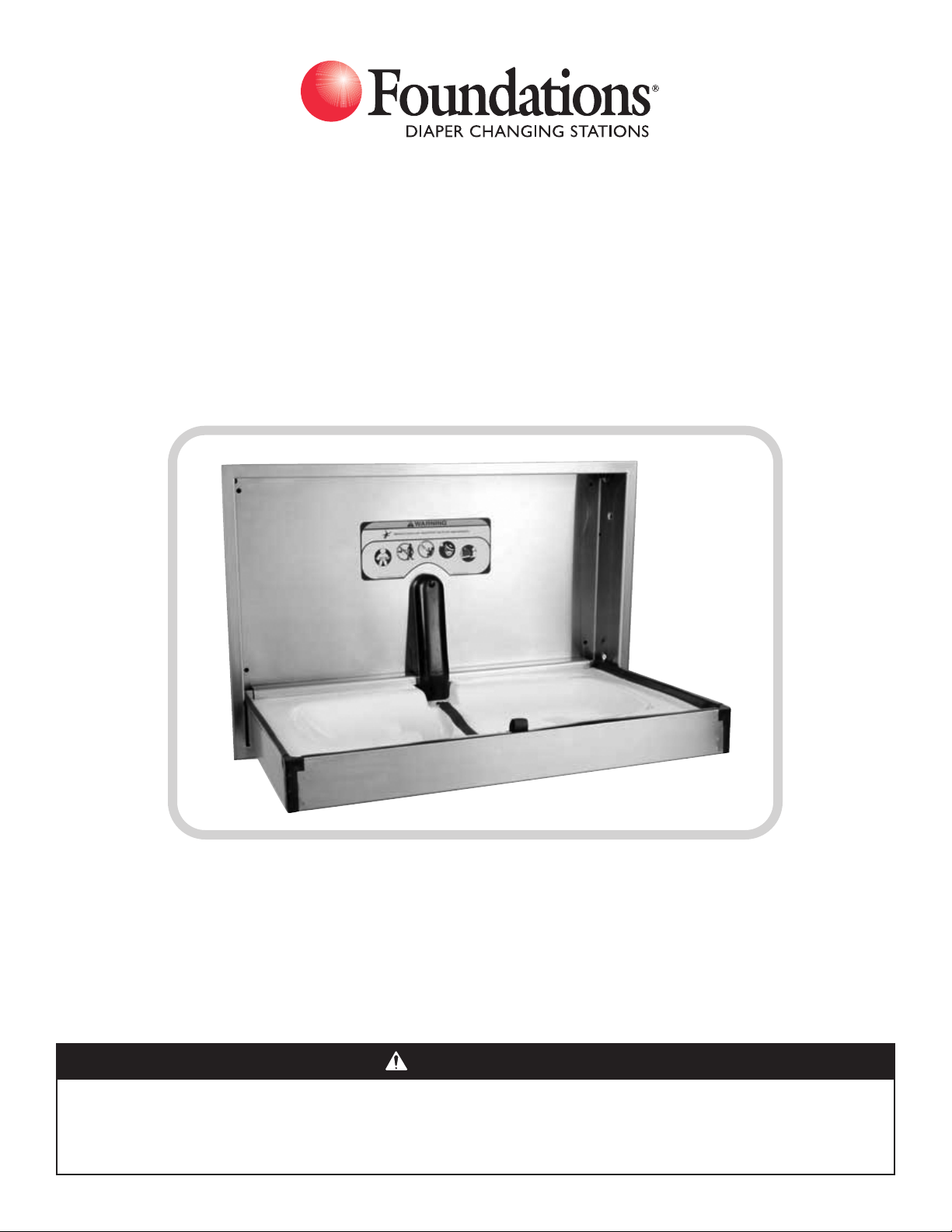
Model 100-SS
Stainless Steel Horizontal Changing Station
Installation Instructions
Thank you for purchasing a quality Foundations®product. Our goal is 100% consumer satisfaction!
If, for any reason you are not satisfied or if you have questions regarding your product or installation,
please contact our customer service team at 1-877-716-2757. Please DO NOT contact your distributor
or reseller as we are better prepared to assist you.
WARNING
• Failure to follow these warnings and the installation instructions could result in serious injury
or death.
• Read all instructions before installing diaper changing station. Keep these instructions. DO NOT
discard.
SI259D
Page 2
ASSEMBLY INSTRUCTIONS
ADULT INSTALLATION REQUIRED.
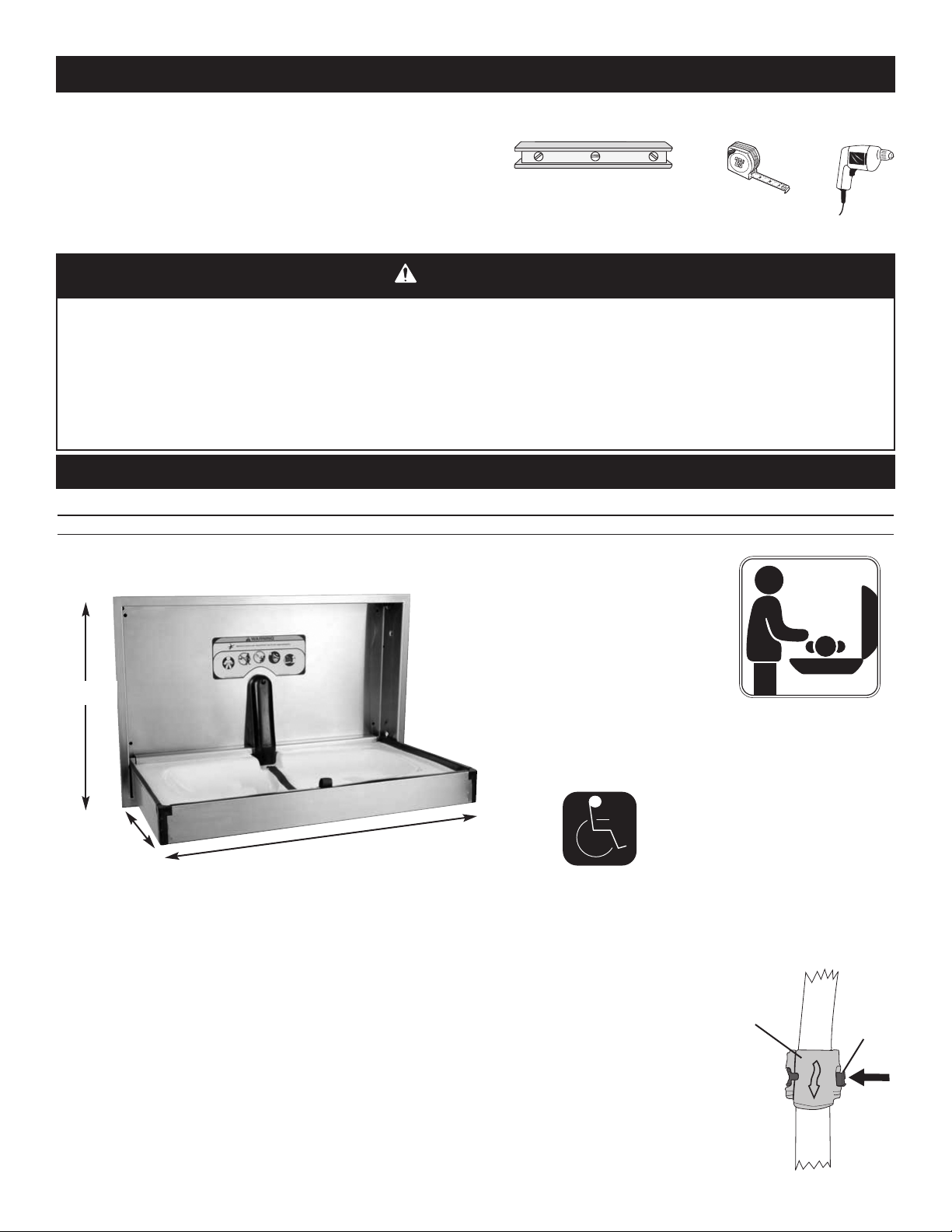
TOOLS REQUIRED:
A
BC
Level (A)
Measuring tape (B)
ower drill (C)
P
EAD ALL INSTRUCTIONS BEFORE ASSEMBLY OF DIAPER CHANGING STATION
• R
• Unpack carton and identify all parts.
WARNING
This changer has six (6) recess mounting holes.
•
The diaper changing station is no stronger than the anchors or walls to which they are attached and, therefore,
•
MUST be firmly secured in order to support the weight they are intended to support. It is recommended that this unit be
installed in a recessed fashion. If surface mounting, contact an architect, building contractor, or Professional Engineer
for proper installation and hardware. Contact an architect or building contractor if any questions.
Child should never be left unattended.
•
Avoid serious injury from falling or sliding out. Always use restraint system.
•
Adding excessive weight such as parcels, packages, or accessories to the unit or to the bag hooks that exceed the total
•
weight limit of 50 pounds (22.7 kg) may cause the unit to be unstable or may cause a hazardous unstable condition to
exist.
PARTS LIST
Parts Description Quantity
Door / Wall Plate 1
IMPORTANT: Due to widely varied wall material,
anchoring to be determined by architect or engineer.
21 3/8
(543 mm)
18”
(457 mm) (R)
21-3/8”
(543 mm) (SM)
34”
(864 mm)
A.D.A. Compliance:
4.4.1 Maximum Protruding Objects
4.2.5 Forward Reach
4.2.6 Parallel Approach
4.27.4 Operation
Compliant when properly installed.
Door / wall plate to be
mounted on outside of
restroom door.
OPERATION:
Rotate base downward. Place infant on top of the changing surface. Use restraint system as described below. After child has been
changed, remove restraint system and rotate base back up against the wall.
USE OF RESTRAINT SYSTEM:
Place child so restraint strap is located at abdomen. Rotate top of buckle upward and insert strap
in buckle. Pull strap through buckle until snug against infant. Rotate top of buckle downward to lock
the strap into place. Slide red locking tab over top of buckle (Fig. a). Reverse steps to loosen strap.
MAINTENANCE AND CLEANING:
Check all hardware and components monthly or as required to ensure hardware is tight and there
are no missing or damaged components. Take unit out of service if any component is missing or
damaged and contact customer service to order replacement parts. Do not substitute parts.
For replacement parts, contact customer service at 1-877-716-2757.
Clean by using a damp cloth with mild soap or mild multi-purpose cleaner. Do not use any strong
chemical cleaners or cleaning agents that may be hazardous to children.
Top Of
Buckle
Locking
Fig. a
1
Tab
Page 3
INSTALLATION - RECESSED
3
4 1/2" (876 mm)
R
ough-in
Double Stud
Double Stud
Double Stud
Double Stud
3 7/8"
(98.4 mm)
1"
(25.4 mm)
21 3/4"
(552 mm)
Rough-in
34 1/2"
(876 mm)
For A. D. A.
Compliance
30.5”
(78 cm)
T
OP
VIEW
F
RONT
VIEW
A. F. F
19.4"
(492 mm)
1
4
”
(
3
5
6
m
m
)
o
n
c
e
n
te
r
32"
(813 mm)
on center
To p
For A. D. A.
Compliance
50 1/4”
(128 cm)
A. F. F
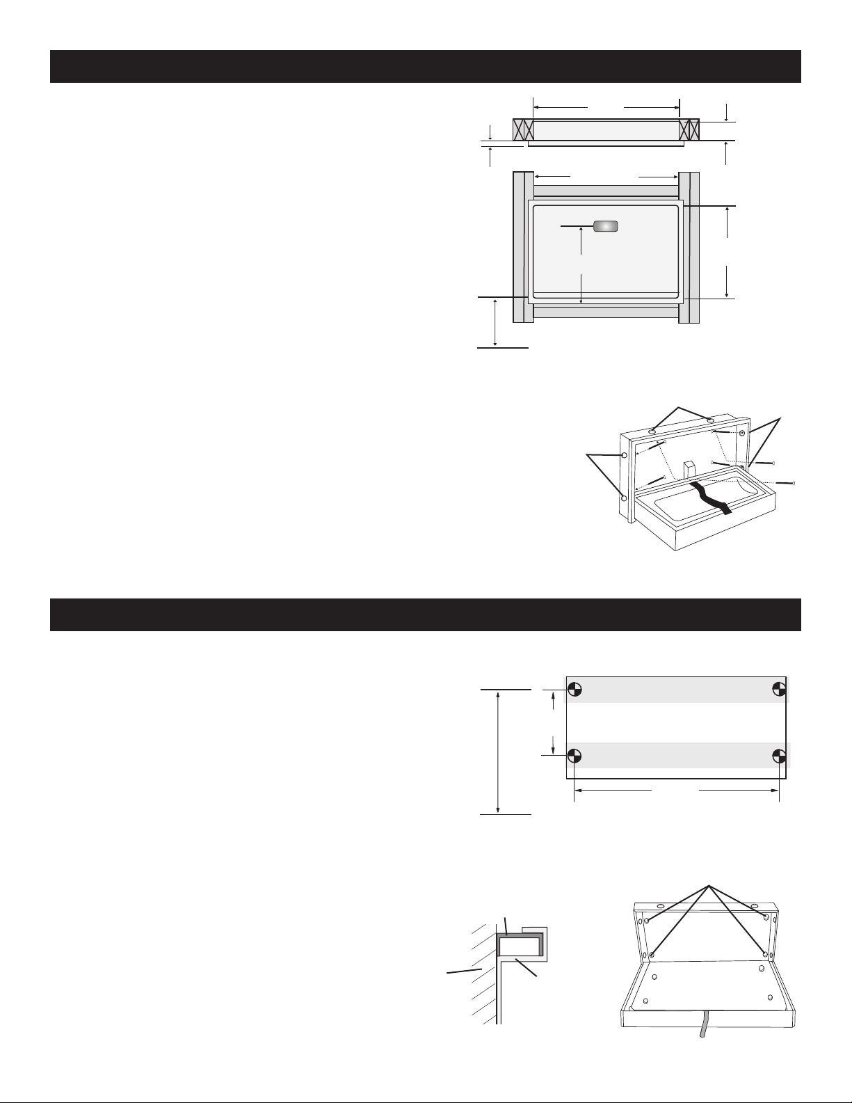
For A. D. A. compliance, top of lower double stud should be
30.5“ (78 cm) from the floor.
ecommended Blocking:
R
Wood double stud blocking is necessary. Contact an architect
and building official to make sure the blocking is adequate and
complies with building codes (Fig b).
1. Slide changer into blocking area and mark mounting hole
location on blocking studs.
HINT: This may require 2 additional people to help hold
changer in position while you are marking the locations.
2. Shim changer for a snug fit.
3. Align holes in changer with marked holes and secure using
the appropriate fasteners (Fig. c).
NOTE: It is installers responsibility to provide correct
fastereners for other substrates.
4. Ensure all six (6) fasteners are tight.
INSTALLATION - SURFACE-MOUNT
Recommended Blocking:
If the walls do not have studs on center, then additional blocking
is necessary (Fig. d).
Contact an architect or building contractor to make sure the
blocking is adequate and complies with building codes.
Recess
Mounting
Holes
Fig. b
Recess
Mounting
Holes
Recess
Mounting
Holes
Fig. c
For A. D. A. compliance, measure up 50 1/4” (128 cm) from the
floor and mark the wall. This locates the position for the top
left attachment hole.
NOTE:
- Changer MUST be mounted to studs (Fig. e).
- This unit incorporates a finishing collar that seats behind
the changer’s outside flange. Center the collar as the
unit is being tightened against the wall (Fig. f).
Wall
2
Fig. d
Surface-Mount
Holes
Collar
Unit
Fig. f
Fig. e
 Loading...