

Foundation FP-68KM4, FP-102KM4, FP-136KM4, FP-80KM4, FP-170KM4 Installation And Operation Manual
...
Installation and Operation Manual
Hydronic Ceiling Cassette Fan Coil Units
FP-KM
4-pipe system
Last update: 10.04.2009

CONTENT
PAGE
MODEL ASSIGNMENTS………………………………..…………………….…………. 3
SPECIFICATIONS………………………………………………………………..………..
4
a) COOLING CAPACITY TABLES…………………….………………….……….
b) HEATING CAPACITY TABLES…………………………..…………………….
INSTALLATION MANUAL………………………………………………….……………..
a) SAFETY CONSIDERATIONS…………………………………………..………
b) OPERATING LIMITS…………………………………………………………….
c) BEFORE INSTALLATION……………………………………………………….
d) SELECT LOCATION……………………………………………………………..
e) INSTALLATION LOCATION…………………………………………………….
f) INSTALLATION METHOD………………………………………………………
g) DRAIN PIPEWORK………………………………………………………………
h) WATER CONNECTIONS………………………………………………………..
i) INTERCONNECTING WIRING…………………………………………………
j) MOUNTING FRONT PANEL …………………………………………………...
k) FILTER REMOVAL………………………………………………………………
l) PRELIMINARY CHECKS BEFORE START-UP……………………………...
m) MAINTENANCE…………………………………………………………………..
n) FRESH AIR RENEWAL AND BRANCH DUCTING…………………………..
o) BRANCH DUCT AND FRESH AIR DUCT INSTALLATION ………………...
p) BRANCH DUCT AND FRESH AIR DUCT POSITIONS…..…………………
6
10
14
14
14
15
15
15
16
19
19
20
21
21
22
22
24
26
27
DIMENSIONAL DRAWINGS………………………………………………..…………… 28
REMOTE CONTROLLER…………………………….………..……..………………..… 34
WIRED WALL PAD CONTROL…………………………………………………………
CONTROLS SPECIFICATION WITH MASTER-SLAVE CONTROL & COMPUTER
MANAGEMENT CONTROL………………………………………………………………
WIRING DIAGRAM…………………………………………………………..……………
SOLENOID VALVE …………………………………………………………………….…
TROUBLESHOOTING ……………………………………………………………………
APPENDIX 1: SOFTWARE INSTALLATION
35
36
43
46
48
49
Page 3 of 49
Ceiling cassette
Fan
Coil Unit
, 4-pipe system
Model: FP-
KM
MODEL ASSIGNMENTS
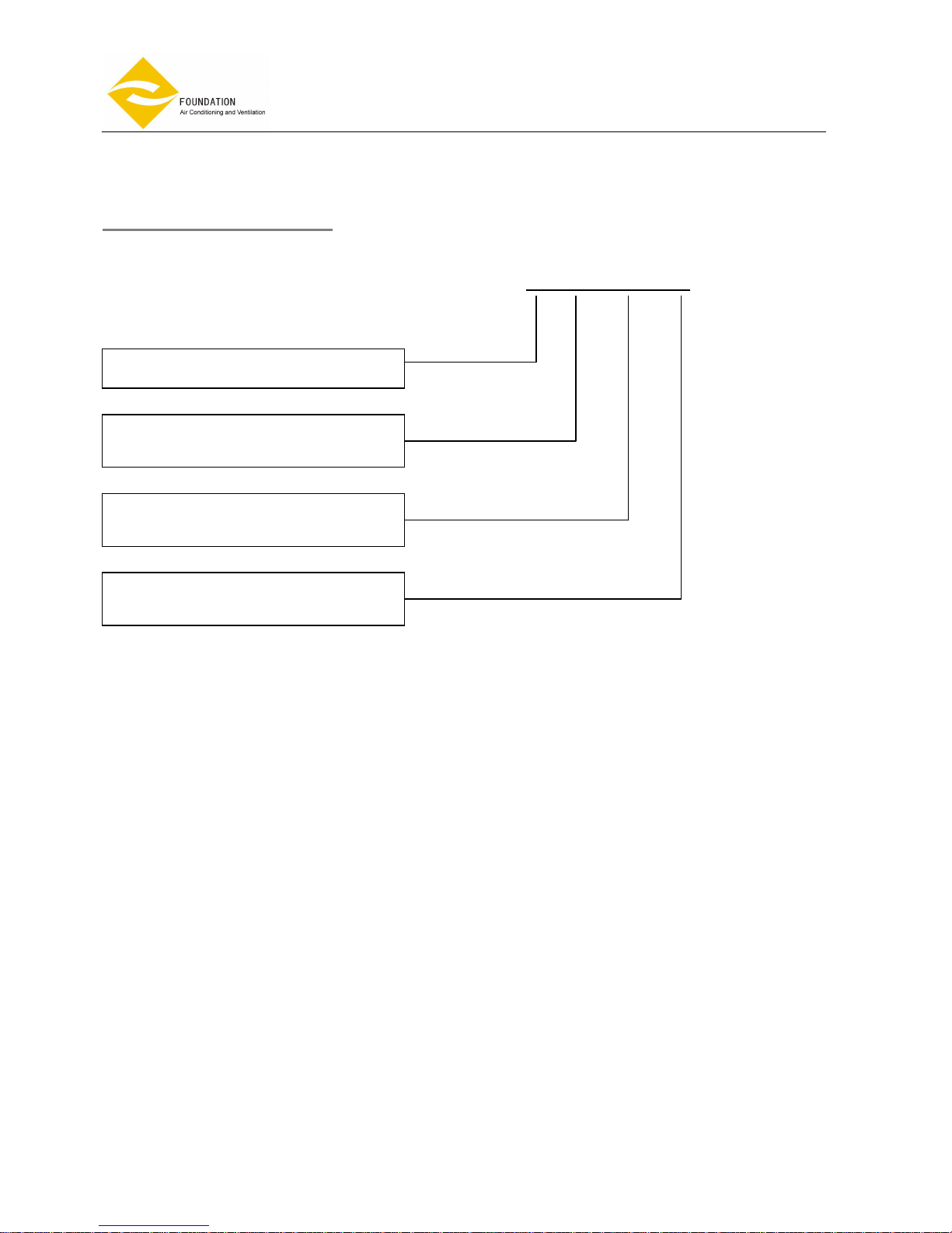
FP - 34 - KM4 – S
Fan Coil Unit
Model
KM4: 4-way cassette
KM6: 6-way cassette
A: 220
-240V / 1PH / 50HZ
S: 230V / 1PH / 50HZ
Page 4 of 49
Ceiling cassette
Fan
Coil Unit
, 4-pipe system
Model: FP-
KM
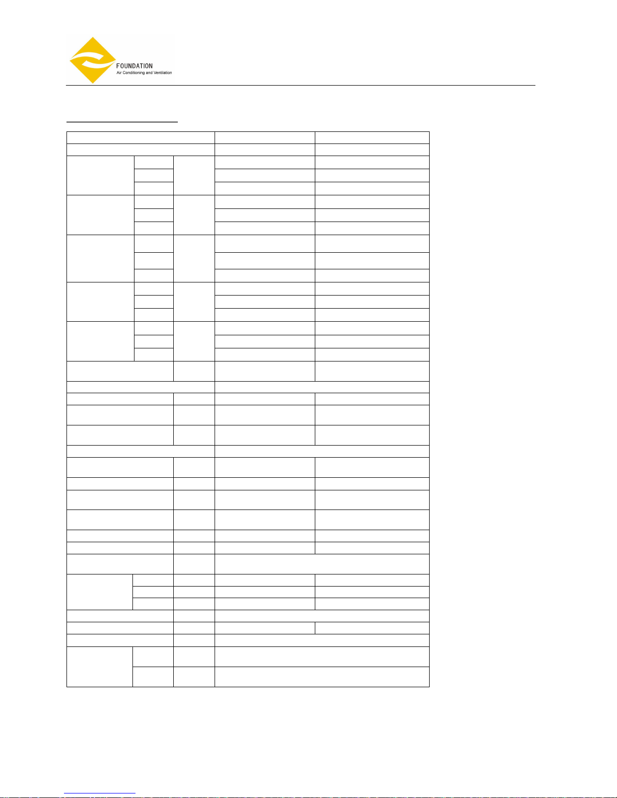
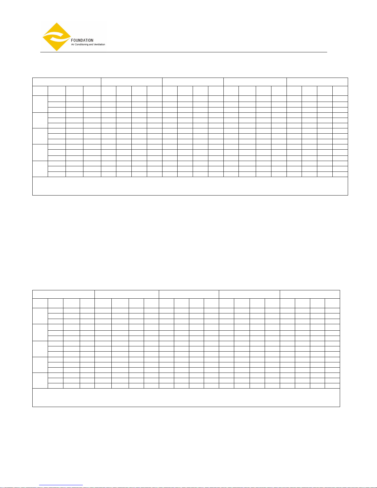
SPECIFICATIONS
Model
FP-68KM4 FP-80KM4
Number Of Fan Blowers Single Single
H 624 (173) 768 (213)
M 564 (157) 624 (173)
Nominal
Airflow
L
m3/h
(l/s)
468 (130) 516 (143)
H 3.2 3.8
M 2.8 3.2
Nominal
Cooling
Capacity*
L
KW
2.4 2.7
H 2.3 2.4
M 2.0 2.1
Nominal
Sensible
Cooling
Capacity
L
KW
1.8 1.9
H 3.2 3.4
M 2.8 3.0
Nominal
Heating
Capacity**
L
KW
2.5 2.7
H 1.55 1.65
M 1.4 1.5
Nominal
Heating
Capacity***
L
KW
1.3 1.3
Noise Level at
1 m(L/M/H)
dB(A) 39/41/43 42/44/46
Power Supply 230V/1PHASE/50HZ
Fan Motor Power Watt 58 61.1
Fan Motor Running
Current
Amp. 0.253 0.264
Fan Motor Starting
Current
Amp. 0.759 0.792
Operation Control & Thermostat Remote Controller and wiring controller
Chiller Water Flow
Rate
1/h 610 700
Heat Water Flow Rate 1/h 300 315
Chilled Water Pressure
Drop
KPa 9.7 12.4
Hot Water Pressure
Drop
KPa 1.1 1.2
Chilled Water Content 1 0.9015 0.9015
Hot Water Content 0.366 0.366
Cond. Drain
Connection I.D.
mm
(inch)
19.05(3/4〃)
L mm 575 575
W mm 575 575
Casing
Dimensions
D mm 290 290
Panel Dimensions mm
680×680×30
Gross Weight kgs 32 32
Connection Method Socket(Threaded Female)
In
mm
(inch)
19.05(3/4〃)
Water
Connection
Out
mm
(inch)
19.05(3/4〃)
Cooling *:27°C db/19.5°C wb entering air temperature,7°C entering water and 12°C leaving water temperature.
Heating**:20°C db entering air temperature ,70°C entering water and 60°C leaving water.
Heating***:20°C db entering air temperature, 50°C entering water and 40°C leaving water.
Page 5 of 49
Ceiling cassette
Fan
Coil Unit
, 4-pipe system
Model: FP-
KM
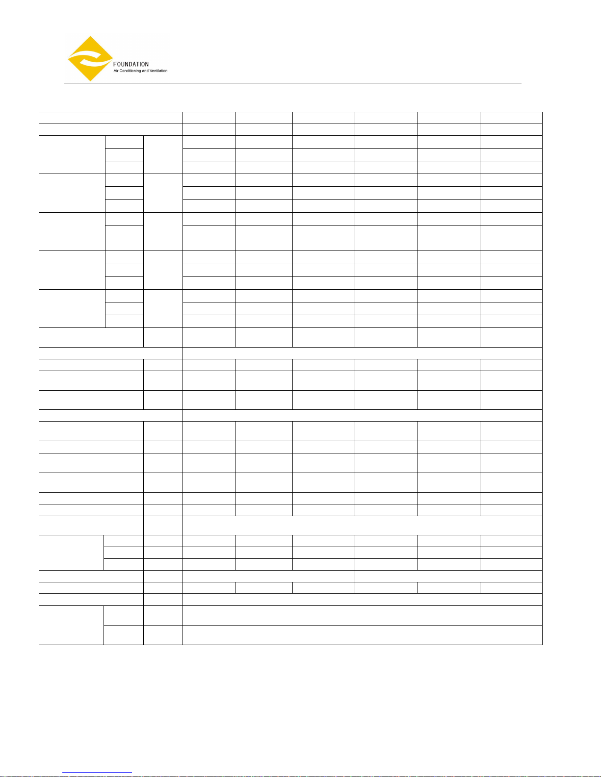
Model
FP-85KM4 FP-102KM4 FP-136KM4 FP-170KM4 FP-204KM4 FP-238KM4
Number Of Fan Blowers Single Single Single Single Single Single
H 852 (237) 1020 (283) 1360 (378) 1700 (472) 2040 (567) 2380 (661)
M 648 (180) 780 (217) 1050 (292) 1310 (364) 1570 (436) 1830 (508)
Nominal
Airflow
L
m3/h
(l/s)
498 (138) 600 (167) 800 (222) 1010 (281) 1210 (336) 1410 (392)
H 4.5 5.2 5.8 7.7 8.5 9.0
M 3.6 4.2 4.7 6.2 6.8 7.3
Nominal
Cooling
Capacity*
L
KW
2.9 3.3 3.7 5.0 5.5 5.9
H 3.1 3.5 4.2 5.6 6.3 7.0
M 2.6 3.0 3.6 4.8 5.4 6.0
Nominal
Sensible
Cooling
Capacity
L
KW
2.2 2.5 3.0 4.0 4.6 5.1
H 4.4 4.8 5.7 7.95 8.8 9.6
M 3.7 4.1 4.9 6.8 7.6 8.3
Nominal
Heating
Capacity**
L
KW
3.2 3.5 4.2 5.85 6.5 7.1
H 2.2 2.5 2.9 4.1 4.6 4.95
M 1.9 2.1 2.5 3.6 3.95 4.27
Nominal
Heating
Capacity***
L
KW
1.6 1.8 2.1 3.1 3.4 3.37
Noise Level at
1 m(L/M/H)
dB(A) 37/39/42 39/42/45 46/49/53 48/51/54 45/51/55 47/53/59
Power Supply 230V/1PHASE/50HZ
Fan Motor Power Watt 70.2 80.5 100 150 192 241
Fan Motor Running
Current
Amp. 0.305 0.367 0.435 0.652 0.844 1.079
Fan Motor Starting
Current
Amp. 0.915 1.1 1.31 1.956 2.532 3.237
Operation Control & Thermostat Remote Controller and wiring controller
Chiller Water Flow
Rate
1/h 846 980 1088 1452 1600 1688
Hot Water Flow Rate 1/h 408 453 533 748 830 905
Chiller Water Pressure
Drop
KPa 23.7 25.4 26.8 23.5 25.4 28.5
Hot Water Pressure
Drop
KPa 2.5 3.1 4.27 10.4 12.6 14.7
Chilled Water Content 1 1.262 1.262 1.262 1.262 1.262 1.262
HOT Water Content 1 0.7719 0.7719 0.7719 0.7719 0.7719 0.7719
Cond. Drain
Connection I.D.
mm
(inch)
19.05(3/4〃)
L mm 730 730 730 860 860 860
W mm 730 730 730 860 860 860
Casing
Dimensions
D mm 290 290 290 290 290 290
Panel Dimensions mm
830×830×30 980×980×30
Gross Weight kgs 44 44 44 62 62 62
Connection Method Socket(Threaded Female)
In
mm
(inch)
19.05(3/4〃)
Water
Connection
Out
mm
(inch)
19.05(3/4〃)
Cooling *:27°C db/19.5°C wb entering air temperature,7°C entering water and 12°C leaving water temperature.
Heating**:20°C db entering air temperature ,70°C entering water and 60°C leaving water.
Heating***:20°C db entering air temperature, 50°C entering water and 40°C leaving water.
Page 6 of 49
Ceiling cassette
Fan
Coil Unit
, 4-pipe system
Model: FP-
KM
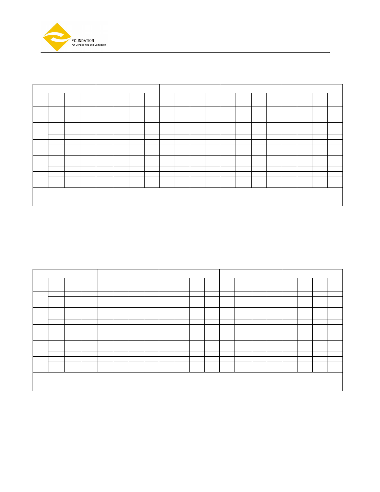
COOLING CAPACITY TABLE
FP-68KM4
TAI DB25℃-WB17.8℃ TAI DB27℃-WB19℃ TAI DB27℃-WB19.5℃ TAI DB29℃-WB21.1℃
Twi
[℃]
Qw
[1/h]
DPw
[kPa
]
Qa
[m3/h
]
Pf
[kW
]
Pfs
[kW
]
Tad
[℃]
Taw
[℃]
Pf
kW]
Pfs
kW]
Tad
[℃]
Taw
[℃]
Pf
[kW
]
Pfs
[kW
]
Tad
[℃]
Taw
[℃]
Pf
kW]
Pfs
kW]
Tad
[℃]
Taw
[℃]
523 7.45 461 2.34 1.98 12.5 12.4 2.65 2.07 13.9 13.1 2.77 1.98 14.4 13.4 3.34 2.07 15.8 14.1
617 10.1 561 2.7 2.19 13.6 12.7 3.12 2.34 14.8 13.3 3.27 2.25 15.2 13.6 3.95 2.36 16.6 14.3
5.0
725 13.4 681 3.15 2.47 14.4 12.9 3.66 2.65 15.6 13.5 2.84 2.54 16.0 13.8 4.64 2.66 17.4 14.5
444 5.7 462 1.93 1.67 14.4 13.4 2.22 1.83 15.3 14.1 2.35 1.77 15.7 14.4 2.85 1.84 17.2 15.2
520 7.6 560 2.2 1.92 15 13.7 2.6 2.08 16.1 14.3 2.75 1.99 16.5 14.6 3.35 2.08 18 15.4
7.0
606 9.7 682 2.54 2.2 15.5 13.9 3.02 2.35 16.8 14.5 3.21 2.26 17.2 14.8 3.93 2.33 18.8 15.6
312 2.93 463 1.25 1.22 17.2 15 1.57 1.53 17.2 15.6 1.65 1.55 17.1 16 2.03 1.65 18.4 17
357 3.74 562 1.36 1.32 18 15.3 1.8 1.76 17.7 15.8 1.89 1.76 17.7 16.2 2.35 1.84 19.2 17.2
9.0
408 4.76 682 1.52 1.49 18.5 15.5 2.05 1.99 18.3 16 2.16 1.99 18.3 16.4 2.71 2.07 19.9 17.4
259 2.1 462 1.16 1.14 17.7 15.2 1.34 1.31 18.5 16.1 1.37 1.30 18.6 16.6 1.75 1.36 20.2 17.6
295 2.65 563 1.2 1.17 18.8 15.6 1.52 1.48 19.1 16.3 1.56 1.47 19.2 16.8 2.0 1.53 20.8 17.8
11.0
330 3.26 682 1.26 1.23 19.6 15.9 1.72 1.67 19.7 16.5 1.75 1.66 19.7 17 2.28 1.72 21.4 18
206 1.39 461 0.81 0.79 19.9 16 1.07 1.05 20.2 16.7 1.09 1.05 20.2 17.2 1.3 1.19 21.2 18.5
230 1.7 563 0.82 0.80 20.7 16.3 1.19 1.16 20.8 16.9 1.22 1.183 20.7 17.4 1.48 1.35 21.8 18.7
13.0
253 2.02 683 0.87 0.84 21.3 16.5 1.31 1.27 21.4 17.1 1.34 1.29 21.3 17.6 1.64 1.52 22.3 18.9
Pf: total cooling capacity Tal: in flow air temperature dpw: pressure drop standard coil
Twi: in flow fluid temperature Qw: fluid flow rate in heat exchanger Qa: air flow
Pfs: sensible cooling capacity Tad: discharge air dry temperature Taw: discharge air wet temperature
Note
: For cooling condition: temperature different between incoming/outgoing water is 5 degree Celsius.
Design and specification are subject to change without prior notice for product Improvement.
COOLING CAPACITY TABLE
FP-80KM4
TAI DB25℃-WB17.8℃ TAI DB27℃-WB19℃ TAI DB27℃-WB19.5℃ TAI DB29℃-WB21.1℃
Twi
[℃]
Qw
[1/h
]
DPw
[kPa
]
Qa
[m3/h
]
Pf
[kW]
Pfs
[kW
]
Tad
[℃]
Taw
[℃]
Pf
kW]
Pfs
kW]
Tad
[℃]
Taw
[℃
]
Pf
[kW
]
Pfs
[kW
]
Tad
[℃]
Taw
[℃]
Pf
kW]
Pfs
kW]
Tad
[℃]
Taw
[℃]
612 9.88 516 2.7 2.05 13.4 12.2 3.17 2.19 14.5 12.6 3.24 2.13 14.9 13.1 3.81 2.26 16.1 13.9
718 13.2 624 3.16 2.33 14.1 12.4 3.68 2.49 15.3 12.9 3.8 2.4 15.7 13.3 4.49 2.53 17 14.1
5.0
840 17.5 751 3.66 2.61 14.8 12.6 4.28 2.78 16.1 13.1 4.43 2.67 16.5 13.5 5.25 2.83 17.8 14.3
514 7.21 516 2.2 1.81 14.7 13.3 2.63 1.95 15.9 13.8 2.72 1.87 16.3 14.2 3.28 1.98 17.6 15
599 9.5 624 2.52 2.06 15.2 13.5 3.06 2.2 16.6 14 3.17 2.11 17 14.4 3.84 2.23 18.4 15.2
7.0
693 12.4 750 2.93 2.32 15.9 13.7 3.53 2.46 17.3 14.2 3.67 2.35 17.7 14.6 4.47 2.47 19.2 15.4
366 3.92 517 1.44 1.41 16.9 14.9 1.85 1.72 17.1 15.4 1.94 1.64 17.6 15.8 2.46 1.72 19.2 16.7
421 5.04 626 1.63 1.58 17.5 15.1 2.12 1.96 17.7 15.6 2.23 1.85 18.2 16 2.8 1.94 19.7 16.9
9.0
478 6.33 752 1.82 1.77 18 15.3 2.4 2.19 18.3 15.8 2.53 2.1 18.7 16.2 3.21 2.15 20.4 17.1
270 2.27 517 1.05 1.02 19.1 15.7 1.4 1.37 19.1 16.3 1.43 1.38 19 16.8 1.73 1.53 20.1 18
302 2.77 624 1.16 1.13 19.6 15.9 1.57 1.52 19.7 16.5 1.6 1.56 19.5 17 1.96 1.72 20.7 18.2
11.0
350 3.6 750 1.245 1.2 20.2 16.1 1.74 1.7 20.2 16.7 1.85 1.80 19.8 17.1 2.28 1.92 21.3 18.3
212 1.46 518 0.605 0.582 21.6 16.6 1.1 1.07 20.8 16.9 1.12 1.09 20.7 17.4 1.35 1.31 21.4 18.7
233 1.73 626 0.675 0.644 21.9 16.7 1.2 1.16 21.4 17.1 1.23 1.19 21.3 17.6 1.5 1.45 22 18.9
13.0
250 1.96 751 0.74 0.7 22.2 16.8 1.29 1.25 22 17.3 1.32 1.27 21.9 17.8 1.64 1.59 22.6 19.1
Pf: total cooling capacity Tal: in flow air temperature dpw: pressure drop standard coil
Twi: in flow fluid temperature Qw: fluid flow rate in heat exchanger Qa: air flow
Pfs: sensible cooling capacity Tad: discharge air dry temperature Taw: discharge air wet temperature
Note
: For cooling condition: temperature different between incoming/outgoing water is 5 degree Celsius.
Design and specification are subject to change without prior notice for product Improvement.
Page 7 of 49
Ceiling cassette
Fan
Coil Unit
, 4-pipe system
Model: FP-
KM
COOLING CAPACITY TABLE
FP-85KM4
TAI DB25℃-WB17.8℃ TAI DB27℃-WB19℃ TAI DB27℃-WB19.5℃ TAI DB29℃-WB21.1℃
Twi
[℃]
Qw
[1/h
]
DPw
[kPa
]
Qa
[m3/h
]
Pf
[kW]
Pfs
[kW
]
Tad
[℃]
Taw
[℃]
Pf
kW]
Pfs
kW]
Tad
[℃]
Taw
[℃
]
Pf
[kW
]
Pfs
[kW
]
Tad
[℃]
Taw
[℃]
Pf
kW]
Pfs
kW]
Tad
[℃]
Taw
[℃]
604 10.4 501 2.71 2.24 12 12 3.1 2.48 12.6 12.6 3.2 2.4 13.0 13.0 3.85 2.63 13.6 13.6
750 15.4 651 3.35 2.81 12.4 12.3 3.84 3.02 13.4 12.9 3.98 2.96 13.7 13.3 4.82 3.12 14.9 13.9
5.0
950 23.5 850 4.23 3.35 13.5 12.5 4.86 3.62 14.5 13.1 5.03 3.5 14.9 13.5 6.12 3.68 16.2 14.1
534 8.3 500 2.36 2.06 13 12.8 2.73 2.25 13.8 13.4 2.83 2.18 14.2 13.8 3.47 2.33 15.3 14.4
673 12.6 652 2.95 2.47 13.9 13 3.42 2.7 14.8 13.6 3.56 2.59 15.3 14 4.38 2.75 16.5 14.6
7.0
846 19.0 850 3.7 2.95 14.8 13.2 4.32 3.2 15.9 13.8 4.48 3.08 16.3 14.2 5.56 3.24 17.7 14.8
448 7.5 502 1.91 1.79 14.5 13.8 2.27 1.97 15.4 14.4 2.37 1.89 15.9 14.8 2.8 2.08 16.7 15.8
544 10.7 650 2.36 2.12 15.4 14 2.83 2.34 16.4 14.6 2.88 2.26 16.7 15.1 3.5 2.45 17.8 16
9.0
680 12.8 850 2.93 2.54 16.2 14.2 3.53 2.78 17.3 14.8 3.6 2.69 17.6 15.3 4.41 2.88 18.9 16.2
329 4.33 502 1.35 1.32 17.2 15 1.7 1.66 17.2 15.6 1.74 1.63 17.4 16.1 2.15 1.77 18.5 17.1
400 6.18 650 1.64 1.61 17.7 15.2 2.08 2.01 17.8 15.8 2.12 1.94 18.1 16.3 2.65 2.09 19.4 17.3
11.0
493 9.0 851 1.98 1.92 18.3 15.4 2.56 2.4 18.6 16 2.61 2.31 18.9 16.5 3.29 2.5 20.2 17.5
244 2.53 502 0.93 0.91 19.6 15.9 1.26 1.22 19.7 16.5 1.29 1.26 19.5 17.0 1.52 1.49 20.1 18.3
291 3.47 651 1.08 1.05 20.2 16.1 1.51 1.48 20.2 16.7 1.54 1.5 20.1 17.2 1.84 1.8 20.7 18.5
13.0
348 4.79 850 1.25 1.19 20.8 16.3 1.81 1.76 20.8 16.9 1.84 1.78 20.7 17.4 2.22 2.15 21.4 18.7
Pf: total cooling capacity Tal: in flow air temperature dpw: pressure drop standard coil
Twi: in flow fluid temperature Qw: fluid flow rate in heat exchanger Qa: air flow
Pfs: sensible cooling capacity Tad: discharge air dry temperature Taw: discharge air wet temperature
Note
: For cooling condition: temperature different between incoming/outgoing water is 5 degree Celsius.
Design and specification are subject to change without prior notice for product Improvement.
COOLING CAPACITY TABLE
FP-102KM4
TAI DB25℃-WB17.8℃ TAI DB27℃-WB19℃ TAI DB27℃-WB19.5℃ TAI DB29℃-WB21.1℃
Twi
[℃]
Qw
[1/h
]
DPw
[kPa
]
Qa
[m3/h
]
Pf
[kW
]
Pfs
[kW
]
Tad
[℃]
Taw
[℃]
Pf
kW]
Pfs
kW]
Tad
[℃]
Taw
[℃
]
Pf
[kW
]
Pfs
[kW
]
Tad
[℃]
Taw
[℃]
Pf
kW]
Pfs
kW]
Tad
[℃]
Taw
[℃]
702 13.6 600 3.15 2.64 12.2 12.2 3.55 2.9 12.9 12.9 3.72 2.81 13.3 13.2 4.46 2.97 14.5 13.9
886 20.6 780 3.95 3.18 13.1 12.4 4.47 3.44 14.1 13.1 4.69 3.322 14.5 13.4 5.63 3.52 15.7 14.1
5.0
1122 31.6 1020 4.98 3.76 14.2 12.6 5.65 4.06 15.3 13.3 5.94 3.95 15.6 13.6 7.16 4.14 17 14.3
620 10.8 600 2.78 2.32 13.7 12.9 3.16 2.55 14.5 13.6 3.28 2.47 14.9 14.0 3.89 2.67 15.9 14.9
778 16.3 781 3.46 2.76 14.6 13.1 3.97 3.02 15.6 13.8 4.12 2.94 15.9 14.2 4.89 3.16 17 15.1
7.0
980 24.7 1021 4.34 3.29 15.5 13.3 5.0 3.6 16.6 14 5.19 3.45 17 14.4 6.19 3.71 18.2 15.3
502 9.29 600 2.19 2.03 15.1 14 2.56 2.22 16.1 14.7 2.66 2.15 16.4 15.1 3.24 2.31 17.6 16
625 13.8 781 2.69 2.41 15.9 14.2 3.17 2.66 16.9 14.9 3.31 2.56 17.3 15.3 4.05 2.75 18.5 16.2
9.0
780 16.3 1022 3.33 2.87 16.7 14.4 3.95 3.16 17.8 15.1 4.13 3.02 18.2 15.5 5.09 3.21 19.6 16.4
393 5.97 601 1.63 1.59 17.2 15.0 1.98 1.92 17.5 15.7 2.08 1.84 17.9 16.1 2.51 2.03 18.9 17.2
481 8.61 781 1.96 1.92 17.7 15.2 2.42 2.28 18.3 15.9 2.55 2.18 18.7 16.3 3.1 2.4 19.8 17.4
11.0
591 12.5 1021 2.37 2.3 18.3 15.4 2.97 2.74 19 16.1 3.13 2.6 19.4 16.5 3.85 2.84 20.7 17.6
280 3.23 600 1.11 1.09 19.6 15.9 1.46 1.43 19.9 16.6 1.48 1.44 19.8 17.1 1.83 1.71 20.5 18.3
334 4.46 781 1.3 1.26 20.2 16.1 1.74 1.7 20.5 16.8 1.77 1.72 20.4 17.3 2.21 2.03 21.2 18.5
13.0
399 6.12 1023 1.5 1.47 20.7 16.3 2.07 2.00 21.1 17 2.11 2.04 21 17.5 2.67 2.37 22 18.7
Pf: total cooling capacity Tal: in flow air temperature dpw: pressure drop standard coil
Twi: in flow fluid temperature Qw: fluid flow rate in heat exchanger Qa: air flow
Pfs: sensible cooling capacity Tad: discharge air dry temperature Taw: discharge air wet temperature
Note
: For cooling condition: temperature different between incoming/outgoing water is 5 degree Celsius.
Design and specification are subject to change without prior notice for product Improvement.

Page 8 of 49
Ceiling cassette
Fan
Coil Unit
, 4-pipe system
Model: FP-
KM
COOLING CAPACITY TABLE
FP-136KM4
TAI DB25℃-WB17.8℃ TAI DB27℃-WB19℃ TAI DB27℃-WB19.5℃ TAI DB29℃-WB21.1℃
Twi
[℃]
Qw
[1/h
]
DPw
[kPa
]
Qa
[m3/h
]
Pf
[kW
]
Pfs
[kW
]
Tad
[℃]
Taw
[℃]
Pf
kW]
Pfs
kW]
Tad
[℃]
Taw
[℃
]
Pf
[kW
]
Pfs
[kW
]
Tad
[℃]
Taw
[℃]
Pf
kW]
Pfs
kW]
Tad
[℃]
Taw
[℃]
882 20.5 800 4.05 3.21 13.3 12.4 4.51 3.5 14.2 13.2 4.67 3.89 14.6 13.6 5.62 3.58 15.8 14.3
1118 31.3 1050 5.13 3.8 14.4 12.6 5.72 4.14 15.4 13.4 5.92 3.99 15.8 13.8 7.17 4.22 17.1 14.5
5.0
1400 47 1360 6.39 4.44 15.4 12.8 7.15 4.84 16.5 13.6 7.41 4.69 16.8 14 9.01 4.85 18.4 14.7
699 13.5 800 3.13 2.84 14.6 13.7 3.56 3.13 15.5 14.5 3.7 3.01 15.9 14.9 4.48 3.22 17.1 15.8
878 20.3 1050 3.91 3.39 15.5 13.9 4.46 3.73 16.5 14.7 4.65 3.58 16.9 15.1 5.66 3.82 18.2 16
7.0
1088 29.5 1360 4.81 4.01 16.3 14.1 5.52 4.36 17.5 14.9 5.76 4.17 17.9 15.3 7.05 4.42 19.3 16.2
525 10.1 802 2.24 2.19 16.9 14.9 2.65 2.6 17.4 15.7 2.78 2.65 17.2 16.1 3.35 2.88 18.3 17.2
648 12 1050 2.74 2.66 17.5 15.1 3.26 3.18 18 15.9 3.43 3.14 18.1 16.3 4.18 3.38 19.4 17.4
9.0
790 16.8 1363 3.29 3.21 18 15.3 3.96 3.89 18.5 16.1 4.18 3.7 18.9 16.5 5.13 3.95 20.3 17.6
389 5.86 802 1.56 1.53 19.3 15.8 1.94 1.9 19.9 16.6 2.06 2.01 19.5 17 2.44 2.39 20.1 18.3
470 8.25 1052 1.85 1.8 19.9 16 2.34 2.28 20.5 16.8 2.49 2.42 20.1 17.2 2.97 2.91 20.7 18.5
11.0
557 11.2 1363 2.1 2.02 20.5 16.2 2.75 2.67 21.1 17 2.95 2.86 20.7 17.4 3.56 3.44 21.4 18.7
283 3.31 806 0.94 0.91 21.6 16.6 1.39 1.37 21.9 17.3 1.5 1.45 21.6 17.7 1.75 1.70 22.6 19.1
329 4.33 1050 1.03 1.01 22.1 16.8 1.6 1.57 22.5 17.5 1.74 1.67 22.2 17.9 2.08 2.02 23.2 19.3
13.0
374 5.46 1363 1.07 1.04 22.7 17 1.8 1.75 23.1 17.7 1.98 1.89 22.8 18.1 2.39 2.34 23.8 19.5
Pf: total cooling capacity Tal: in flow air temperature dpw: pressure drop standard coil
Twi: in flow fluid temperature Qw: fluid flow rate in heat exchanger Qa: air flow
Pfs: sensible cooling capacity Tad: discharge air dry temperature Taw: discharge air wet temperature
Note
: For cooling condition: temperature different between incoming/outgoing water is 5 degree Celsius.
Design and specification are subject to change without prior notice for product Improvement.
COOLING CAPACITY TABLE
FP-170KM4
TAI DB25℃-WB17.8℃ TAI DB27℃-WB19℃ TAI DB27℃-WB19.5℃ TAI DB29℃-WB21.1℃
Twi
[℃
]
Qw
[1/h
]
DPw
[kPa
]
Qa
[m3/h
]
Pf
[kW]
Pfs
[kW
]
Tad
[℃]
Taw
[℃]
Pf
[kW]
Pfs
kW]
Tad
[℃]
Taw
[℃
]
Pf
[kW]
Pfs
[kW
]
Tad
[℃]
Taw
[
℃]
Pf
kW]
Pfs
kW]
Tad
[℃]
Taw
[℃]
1114 12.5 1010 5.04 4.31 12.6 12.5 5.7 4.66 13.5 13.2 5.9 4.55 13.8 13.6 7.05 4.77 15.1 14.3
1397 18.9 1310 6.29 5.11 13.6 12.7 7.14 5.53 14.6 13.4 7.4 5.39 14.9 13.8 8.9 5.71 16.2 14.5
5.0
1752 28.4 1701 7.85 6.03 14.6 12.9 8.95 6.52 15.7 13.6 9.28 6.28 16.1 14 11.12 6.71 17.3 14.8
936 9.2 1011 4.13 3.79 14 13.5 4.68 4.19 14.8 14.3 4.96 4.01 15.3 14.6 5.91 4.37 16.2 15.4
1166 13.7 1311 5.12 4.51 14.9 13.7 5.82 4.98 15.8 14.5 6.18 4.75 16.3 14.8 7.44 5.13 17.4 15.6
7.0
1452 20.3 1701 6.33 5.31 15.8 13.9 7.23 5.87 16.8 14.7 7.69 5.62 17.2 15 9.21 6.17 18.2 15.9
791 8.8 1011 3.58 3.23 15.6 14.1 4.11 3.6 16.5 14.9 4.19 3.48 16.8 15.4 5.03 3.85 17.7 16.3
978 10.1 1312 4.4 3.82 16.4 14.3 5.08 4.25 17.4 15.1 5.18 4.15 17.6 15.6 6.25 4.5 18.8 16.5
9.0
1207 14.9 1703 5.39 4.54 17.1 14.5 6.26 5.04 18.2 15.3 6.39 4.86 18.5 15.8 7.7 5.32 19.7 16.7
586 4.4 1011 2.35 2.28 18.3 15.4 3.05 2.97 18.3 16.0 3.1 2.99 18.2 16.5 3.71 3.35 19.1 17.7
710 5.6 1311 2.8 2.73 18.8 15.6 3.69 3.61 16.8 16.2 3.76 3.56 18.9 16.7 4.53 3.94 20 17.9
11.0
857 7.8 1702 3.31 3.19 19.4 15.8 4.45 4.33 19.4 16.4 4.54 4.21 19.6 16.9 5.52 4.64 20.8 18.1
434 2.3 1015 1.48 1.41 20.8 16.3 2.25 2.2 20.5 16.8 2.3 2.23 20.4 17.3 2.75 2.69 21 18.6
512 3.1 1314 1.67 1.62 21.3 16.5 2.66 2.58 21.1 17 2.71 2.62 21 17.5 3.29 3.18 21.7 18.8
13.0
599 4.11 1704 1.84 1.76 21.9 16.7 3.11 3.0 21.7 17.2 3.17 3.06 21.6 17.7 3.9 3.78 22.3 19
Pf: total cooling capacity Tal: in flow air temperature dpw: pressure drop standard coil
Twi: in flow fluid temperature Qw: fluid flow rate in heat exchanger Qa: air flow
Pfs: sensible cooling capacity Tad: discharge air dry temperature Taw: discharge air wet temperature
Note
: For cooling condition: temperature different between incoming/outgoing water is 5 degree Celsius.
Design and specification are subject to change without prior notice for product Improvement.

Page 9 of 49
Ceiling cassette
Fan
Coil Unit
, 4-pipe system
Model: FP-
KM
COOLING CAPACITY TABLE
FP-204KM4
TAI DB25℃-WB17.8℃ TAI DB27℃-WB19℃ TAI DB27℃-WB19.5℃ TAI DB29℃-WB21.1℃
Twi
[℃
]
Qw
[1/h
]
DPw
[kPa
]
Qa
[m3/h
]
Pf
[kW]
Pfs
[kW
]
Tad
[℃]
Taw
[℃]
Pf
[kW]
Pfs
kW]
Tad
[℃]
Taw
[℃
]
Pf
[kW]
Pfs
[kW
]
Tad
[℃]
Taw
[
℃]
Pf
kW]
Pfs
kW]
Tad
[℃]
Taw
[℃]
1250 15.6 1210 5.5 4.9 13.2 13 6.39 5.29 14.2 13.6 6.62 5.11 14.6 14 7.94 5.46 15.7 14.8
1563 23.2 1570 6.84 5.79 14.2 13.2 7.99 6.25 15.3 13.8 8.28 6.02 15.7 14.2 9.98 6.36 17 15
5.0
1958 35 2040 8.51 6.87 15.1 13.4 9.99 7.32 16.4 14 10.37 7.03 16.8 14.4 12.56 7.41 18.2 15.2
1035 11 1210 4.62 4.29 14.6 13.8 5.27 4.73 15.5 14.6 5.48 4.55 15.9 15.0 6.53 4.9 17 16
1286 17 1571 5.7 5.07 15.5 14 6.53 5.58 16.5 14.8 6.81 5.36 16.9 15.2 8.15 5.76 18.1 16.2
7.0
1596 24 2042 7.03 6.01 16.3 14.2 8.09 6.53 17.5 15 8.45 6.32 17.8 15.4 10.18 6.7 19.2 16.4
859 7.9 1211 3.95 3.65 16.1 14.4 4.35 4.14 16.9 15.4 4.55 3.96 17.3 15.8 5.56 4.27 18.5 16.8
1058 11.5 1573 4.83 4.3 16.9 14.6 5.33 4.92 17.7 15.6 5.6 4.65 18.2 16.0 6.89 4.99 19.5 17
9.0
1295 16.5 2040 5.89 5.1 17.6 14.8 6.53 5.75 18.6 15.8 6.86 5.47 19 16.2 8.53 5.86 20.4 17.2
657 4.8 1214 2.7 2.65 18.5 15.5 3.4 3.33 18.8 16.2 3.48 3.38 18.7 16.7 4.19 3.77 19.7 17.9
793 7.9 1574 3.2 3.11 19.1 15.7 4.11 4.0 19.4 16.4 4.2 4.0 19.4 16.9 5.1 4.39 20.6 18.1
11.0
952 9.5 2043 3.78 3.63 19.7 15.9 4.94 4.78 20 16.6 5.04 4.71 20.1 17.1 6.2 5.15 21.4 18.3
495 2.9 1211 1.78 1.7 20.8 16.3 2.57 2.50 20.8 16.9 2.62 2.54 20.7 17.4 3.17 3.06 21.4 18.7
583 3.9 1575 2.0 1.94 21.3 16.5 3.02 2.92 21.4 17.1 3.09 2.98 21.3 17.6 3.77 3.65 22 18.9
13.0
678 5.2 2042 2.2 2.1 21.9 16.7 3.52 3.39 22 17.3 3.59 3.45 21.9 17.8 4.46 4.25 22.7 19.1
Pf: total cooling capacity Tal: in flow air temperature dpw: pressure drop standard coil
Twi: in flow fluid temperature Qw: fluid flow rate in heat exchanger Qa: air flow
Pfs: sensible cooling capacity Tad: discharge air dry temperature Taw: discharge air wet temperature
Note
: For cooling condition: temperature different between incoming/outgoing water is 5 degree Celsius.
Design and specification are subject to change without prior notice for product Improvement.
COOLING CAPACITY TABLE
FP-238KM4
TAI DB25℃-WB17.8℃ TAI DB27℃-WB19℃ TAI DB27℃-WB19.5℃ TAI DB29℃-WB21.1℃
Twi
[℃
]
Qw
[1/h
]
DPw
[kPa
]
Qa
[m3/h
]
Pf
[kW]
Pfs
[kW
]
Tad
[℃]
Taw
[℃]
Pf
[kW]
Pfs
kW]
Tad
[℃]
Taw
[℃
]
Pf
[kW]
Pfs
[kW
]
Tad
[℃]
Taw
[
℃]
Pf
kW]
Pfs
kW]
Tad
[℃]
Taw
[℃]
1316 17.2 1420 5.64 5.49 13.6 13.6 6.66 5.9 14.7 14.2 6.97 5.69 15.2 14.6 8.3 6.06 16.3 15.5
1630 25.1 1830 6.91 6.48 14.5 13.8 8.3 6.95 15.8 14.4 8.63 6.69 16.2 14.8 10.4 7.09 17.5 15.7
5.0
2031 37.2 2380 8.64 7.68 15.5 14 10.34 8.13 16.9 14.6 10.76 7.79 17.3 15 13.04 8.23 18.7 15.9
1105 12.4 1411 4.86 4.74 15.1 14.2 5.48 5.27 16 15.1 5.85 5.06 16.4 15.4 7.05 5.42 17.6 16.4
1365 18.1 1830 5.97 5.65 15.9 14.4 6.74 6.24 16.9 15.3 7.23 5.92 17.4 15.6 8.77 6.33 18.7 16.6
7.0
1688 26.6 2382 7.32 6.68 16.7 14.6 8.31 7.38 17.8 15.5 8.94 6.96 18.3 15.8 10.91 7.32 19.8 16.8
897 8.6 1412 4.08 3.96 16.7 14.8 4.52 4.37 17.8 15.8 4.75 4.42 17.7 16.2 5.84 4.75 19.1 17.3
1095 12.2 1832 4.95 4.82 17.2 15 5.51 5.42 18.2 16 5.8 5.23 18.5 16.4 7.09 5.56 19.9 17.5
9.0
1335 17.4 2382 5.98 5.69 17.9 15.2 6.7 6.39 19 16.2 7.07 6.14 19.3 16.6 8.73 6.5 20.8 17.7
712 5.6 1413 3.01 2.94 18.8 15.6 3.69 3.59 19.4 16.4 3.77 3.69 19.2 16.9 4.58 4.14 20.2 18.1
854 8.4 1832 3.56 3.44 19.4 15.8 4.43 4.35 19.9 16.6 4.52 4.41 19.8 17.1 5.56 4.87 21 18.3
11.0
1020 10.7 2384 4.17 4.06 19.9 16 5.29 5.16 20.5 16.8 5.4 5.25 20.4 17.3 6.73 5.69 21.8 18.5
550 3.52 1410 2.07 1.98 20.8 16.3 2.85 2.77 21.1 17 2.91 2.82 21 17.5 3.69 3.42 21.7 18.7
644 4.9 1833 2.33 2.26 21.3 16.5 3.34 3.22 21.7 17.2 3.41 3.29 21.6 17.7 4.4 3.94 22.5 18.9
13.0
746 6.1 2384 2.57 2.45 21.9 16.7 3.87 3.79 22.2 17.4 3.95 3.79 22.2 17.9 5.21 4.56 23.2 19.1
Pf: total cooling capacity Tal: in flow air temperature dpw: pressure drop standard coil
Twi: in flow fluid temperature Qw: fluid flow rate in heat exchanger Qa: air flow
Pfs: sensible cooling capacity Tad: discharge air dry temperature Taw: discharge air wet temperature
Note
: For cooling condition: temperature different between incoming/outgoing water is 5 degree Celsius.
Design and specification are subject to change without prior notice for product Improvement.

Page 10 of 49
Ceiling cassette
Fan
Coil Unit
, 4-pipe system
Model: FP-
KM
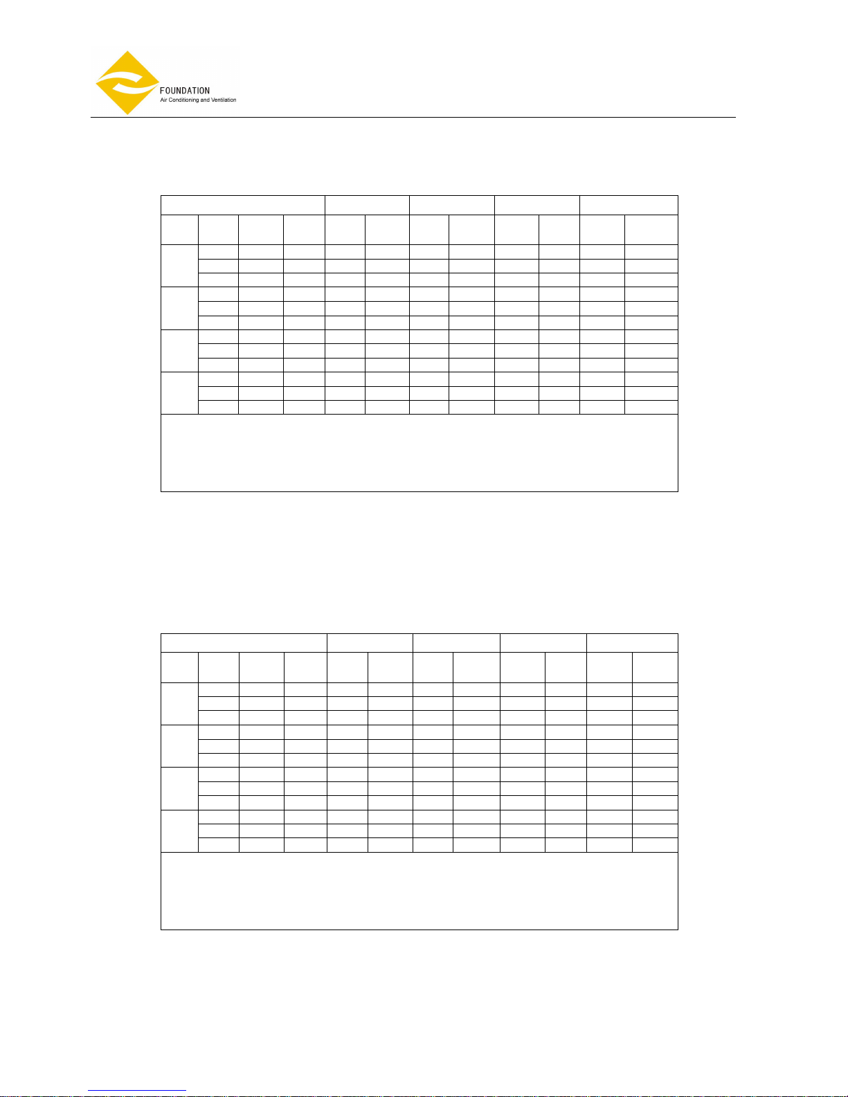
HEATING CAPACITY TABLE
FP-68KM4
TAI 18℃ TAI 20℃ TAI 22℃ TAI 24℃
Twi
[℃
]
Qw
[1/h
]
DPw
[kPa
]
Qa
[m3/h
]
Pf
[kW
]
Tad
[℃]
Pf
kW]
Tad
[℃]
Pf
[kW
]
Tad
[℃]
Pf
kW]
Tad
[℃]
58 0.06 460 0.70 22.7 0.61 24.1 0.58 25.9 0.51 27.4
64 0.07 563 0.78 22.3 0.68 23.7 0.64 25.5 0.57 27.1
40
71 0.08 686 0.87 21.9 0.755 23.4 0.71 25.2 0.63 26.9
116 0.2 466 1.35 27.0 1.23 28.2 1.18 29.8 1.1 31.3
129 0.24 564 1.51 26.3 1.37 27.5 1.32 29.2 1.22 30.7
50
144 0.3 685 1.68 25.6 1.53 26.9 1.47 28.6 1.36 30.2
176 0.42 464 2.17 29.9 1.86 32.3 1.96 32.8 1.71 35.4
196 0.51 564 2.23 30.3 2.08 31.4 2.02 33.1 1.92 34.5
60
220 0.63 684 2.50 29.3 2.33 30.5 2.26 32.2 2.14 33.7
237 0.72 467 2.66 35.6 2.51 36.6 2.45 38.3 2.35 39.5
265 0.88 563 2.97 34.3 2.81 35.4 2.74 37 2.63 38.4
70
296 1.08 688 3.33 33.0 3.14 34.1 3.07 35.8 2.95 37.2
Pf: total heating capacity Tai: in flow air temperature
dpw: pressure drop standard coil Twi: in flow fluid temperature
Qw: fluid flow rate in heat exchanger Qa: air flow
Tad: discharge air temperature
Note
: For heating condition: temperature different between incoming/outgoing water is 10 degree Celsius.
Design and specification are subject to change without prior notice for product Improvement.
HEATING CAPACITY TABLE
FP-80KM4
TAI 18℃ TAI 20℃ TAI 22℃ TAI 24℃
Twi
[℃
]
Qw
[1/h
]
DPw
[kPa
]
Qa
[m3/h
]
Pf
[kW
]
Tad
[℃]
Pf
kW]
Tad
[℃]
Pf
[kW
]
Tad
[℃]
Pf
kW]
Tad
[℃]
61 0.06 512 0.744 22.5 0.65 23.9 0.609 25.7 0.541 27.3
68 0.08 623 0.828 22.1 0.72 23.6 0.677 25.4 0.602 27.0
40
75 0.09 755 0.915 21.7 0.79 23.3 0.749 25.1 0.666 26.7
122 0.22 512 1.425 26.6 1.30 27.8 1.247 29.5 1.157 31.0
137 0.27 624 1.596 25.9 1.45 27.2 1.396 28.9 1.298 30.4
50
152 0.32 754 1.773 25.8 1.61 26.6 1.55 28.4 1.44 29.9
186 0.47 516 2.306 29.4 1.97 31.8 2.09 32.3 1.98 33.7
209 0.57 627 2.38 29.7 2.211 30.93 2.153 32.6 2.04 34.1
60
232 0.69 753 2.642 28.8 2.46 30.1 2.39 31.8 2.264 33.3
250 0.79 512 2.81 34.9 2.65 36.0 2.59 37.7 2.484 39.0
281 0.98 626 3.16 33.6 2.98 34.7 2.92 36.4 2.79 37.8
70
313 1.19 754 3.52 32.4 3.32 33.6 3.24 35.3 3.11 36.8
Pf: total heating capacity Tai: in flow air temperature
dpw: pressure drop standard coil Twi: in flow fluid temperature
Qw: fluid flow rate in heat exchanger Qa: air flow
Tad: discharge air temperature
Note
: For heating condition: temperature different between incoming/outgoing water is 10 degree Celsius.
Design and specification are subject to change without prior notice for product Improvement.
Page 11 of 49
Ceiling cassette
Fan
Coil Unit
, 4-pipe system
Model: FP-
KM
HEATING CAPACITY TABLE
FP-85KM4
TAI 18℃ TAI 20℃ TAI 22℃ TAI 24℃
Twi
[℃
]
Qw
[1/h
]
DPw
[kPa
]
Qa
[m3/h
]
Pf
[kW
]
Tad
[℃]
Pf
kW]
Tad
[℃]
Pf
[kW
]
Tad
[℃]
Pf
kW]
Tad
[℃]
79 0.13 499 0.97 24.0 0.84 25.2 0.79 26.9 0.7 28.4
92 0.17 651 1.13 23.4 0.98 24.7 0.92 26.4 0.82 27.9
40
108 0.23 850 1.31 22.6 1.14 24.1 1.08 25.9 0.96 27.5
150 0.42 501 1.75 28.8 1.59 29.8 1.53 31.5 1.42 32.8
176 0.55 646 2.04 27.8 1.86 28.9 1.79 30.6 1.66 31.9
50
206 0.73 853 2.4 26.7 2.18 27.9 2.1 29.8 1.95 31.1
223 0.85 503 2.54 33.6 2.36 34.5 2.3 36.1 2.18 37.4
261 1.12 647 2.96 32.2 2.76 33.2 2.68 34.8 2.54 36.1
60
306 1.5 849 3.48 30.7 3.24 31.8 3.15 33.5 2.98 34.9
295 1.41 501 3.32 38.5 3.13 39.3 3.07 40.9 2.94 42.0
346 1.87 650 3.89 36.5 3.67 37.5 3.74 38.8 3.442 40.4
70
408 2.51 850 4.57 34.6 4.32 35.7 4.22 37.4 4.05 38.7
Pf: total heating capacity Tai: in flow air temperature
dpw: pressure drop standard coil Twi: in flow fluid temperature
Qw: fluid flow rate in heat exchanger Qa: air flow
Tad: discharge air temperature
Note
: For heating condition: temperature different between incoming/outgoing water is 10 degree Celsius.
Design and specification are subject to change without prior notice for product Improvement.
HEATING CAPACITY TABLE
FP-102KM4
TAI 18℃ TAI 20℃ TAI 22℃ TAI 24℃
Twi
[℃
]
Qw
[1/h
]
DPw
[kPa
]
Qa
[m3/h
]
Pf
[kW
]
Tad
[℃]
Pf
kW]
Tad
[℃]
Pf
[kW
]
Tad
[℃]
Pf
kW]
Tad
[℃]
88 0.16 599 1.07 23.6 0.94 24.8 0.88 26.6 0.78 28
103 0.21 780 1.25 23.0 1.09 24.3 1.03 26.1 0.91 27.6
40
119 0.27 1019 1.45 22.4 1.26 23.8 1.19 25.6 1.06 27.2
168 0.51 598 1.95 28.1 1.78 29.2 1.71 30.9 1.59 32.2
195 0.67 780 2.28 27.1 2.07 28.2 1.99 29.9 1.85 31.3
50
228 0.88 1020 2.66 26.1 2.43 27.3 2.33 29.1 2.16 30.5
249 1.03 600 2.83 32.6 2.63 33.6 2.56 35.2 2.43 36.5
291 1.37 780 3.31 31.1 3.08 32.2 3 33.8 2.84 35.2
60
340 1.81 1021 3.87 29.7 3.6 30.9 3.5 32.6 3.32 34.1
330 1.72 601 3.71 37.1 3.5 38 3.43 39.6 3.29 40.9
387 2.28 782 4.35 35.2 4.1 36.2 4.01 37.9 3.85 39.2
70
453 3.03 1023 5.08 33.4 4.8 34.5 4.65 36.3 4.5 37.6
Pf: total heating capacity Tai: in flow air temperature
dpw: pressure drop standard coil Twi: in flow fluid temperature
Qw: fluid flow rate in heat exchanger Qa: air flow
Tad: discharge air temperature
Note
: For heating condition: temperature different between incoming/outgoing water is 10 degree Celsius.
Design and specification are subject to change without prior notice for product Improvement.

Page 12 of 49
Ceiling cassette
Fan
Coil Unit
, 4-pipe system
Model: FP-
KM
HEATING CAPACITY TABLE
FP-136KM4
TAI 18℃ TAI 20℃ TAI 22℃ TAI 24℃
Twi
[℃
]
Qw
[1/h
]
DPw
[kPa
]
Qa
[m3/h
]
Pf
[kW
]
Tad
[℃]
Pf
kW]
Tad
[℃]
Pf
[kW
]
Tad
[℃]
Pf
kW]
Tad
[℃]
103 0.21 779 1.25 23.0 1.09 24.3 1.03 26.1 0.91 27.6
121 0.28 1048 1.47 22.4 1.28 23.8 1.21 25.6 1.07 27.2
40
139 0.36 1361 1.7 21.9 1.47 23.3 1.39 25.2 1.23 26.8
197 0.68 790 2.3 27.0 2.09 28.2 2.01 29.9 1.87 31.3
232 0.91 1052 2.7 26 2.46 27.2 2.37 29 2.2 30.5
50
268 1.18 1363 3.12 25.1 2.84 26.4 2.74 28.2 2.54 29.8
293 1.38 790 3.34 31.0 3.1 32.1 3.02 33.8 2.86 35.2
346 1.87 1051 4.4 28 3.66 30.8 3.98 31 3.77 32.6
60
400 2.43 1361 4.56 28.4 4.24 29.6 4.12 31.4 3.91 32.9
390 2.31 790 4.38 35.1 4.13 36.2 4.04 37.7 3.87 39.1
461 3.13 1047 5.16 33.3 4.88 34.4 4.77 36.1 4.57 37.5
70
533 4.27 1360 5.99 31.6 5.65 32.8 5.53 34.6 5.30 36
Pf: total heating capacity Tai: in flow air temperature
dpw: pressure drop standard coil Twi: in flow fluid temperature
Qw: fluid flow rate in heat exchanger Qa: air flow
Tad: discharge air temperature
Note
: For heating condition: temperature different between incoming/outgoing water is 10 degree Celsius.
Design and specification are subject to change without prior notice for product Improvement.
HEATING CAPACITY TABLE
FP-170KM4
TAI 18℃ TAI 20℃ TAI 22℃ TAI 24℃
Twi
[℃
]
Qw
[1/h
]
DPw
[kPa
]
Qa
[m3/h
]
Pf
[kW
]
Tad
[℃]
Pf
kW]
Tad
[℃]
Pf
[kW
]
Tad
[℃]
Pf
kW]
Tad
[℃]
156 0.62 1009 1.90 23.8 1.65 25.1 1.56 26.8 1.38 28.2
181 0.81 1310 2.11 23 1.92 24.5 1.81 26.3 1.61 27.8
40
210 1.06 1698 2.56 22.7 2.33 24.2 2.1 25.8 1.86 27.4
286 1.84 1011 3.33 28.2 3.03 29.3 2.91 30.9 2.71 32.3
333 2.43 1311 3.88 27.2 3.53 28.3 3.4 30 3.15 31.4
50
387 3.18 1701 4.51 26.2 4.10 27.5 3.95 29.2 3.66 30.7
417 3.64 1012 4.75 32.5 4.42 33.5 4.3 35.1 4.07 36.4
487 4.8 1311 5.54 31.1 5.16 32.2 5.02 33.8 4.76 35.2
60
566 6.31 1701 6.45 29.7 6.0 30.9 5.83 32.6 5.53 34
549 5.97 1010 6.16 36.9 5.82 37.8 5.69 39.4 5.45 40.7
642 7.9 1309 7.2 35.0 6.8 36.1 6.64 37.7 6.37 39
70
748 10.4 1700 8.39 33.2 7.92 34.4 7.75 36.1 7.42 37.5
Pf: total heating capacity Tai: in flow air temperature
dpw: pressure drop standard coil Twi: in flow fluid temperature
Qw: fluid flow rate in heat exchanger Qa: air flow
Tad: discharge air temperature
Note
: For heating condition: temperature different between incoming/outgoing water is 10 degree Celsius.
Design and specification are subject to change without prior notice for product Improvement.

Page 13 of 49
Ceiling cassette
Fan
Coil Unit
, 4-pipe system
Model: FP-
KM
HEATING CAPACITY TABLE
FP-204KM4
TAI 18℃ TAI 20℃ TAI 22℃ TAI 24℃
Twi
[℃
]
Qw
[1/h
]
DPw
[kPa
]
Qa
[m3/h
]
Pf
[kW
]
Tad
[℃]
Pf
kW]
Tad
[℃]
Pf
[kW
]
Tad
[℃]
Pf
kW]
Tad
[℃]
173 0.75 1209 2.11 23.4 1.84 24.7 1.73 26.4 1.54 27.9
201 0.98 1569 2.45 22.8 2.13 24.2 2.01 26 1.78 27.5
40
232 1.27 2041 2.85 22.1 2.46 23.7 2.32 25.5 2.06 27.1
318 2.23 1210 3.7 27.5 3.37 28.6 3.24 30.3 3.01 31.7
370 2.93 1570 4.31 26.5 3.92 27.7 3.77 29.4 3.5 30.9
50
429 3.82 2042 5.0 25.6 4.54 26.9 4.38 28.6 4.06 30.1
464 4.41 1211 5.29 31.5 4.92 32.6 4.78 34.2 4.53 35.6
541 5.81 1570 6.16 30.1 5.73 31.3 5.57 33 5.28 34.4
60
629 7.61 2038 7.15 28.8 6.66 30.1 6.47 31.8 6.13 33.3
612 7.26 1210 6.87 35.5 6.49 36.6 6.34 38.2 6.08 39.5
714 9.56 1570 8.01 33.8 7.56 34.9 7.4 36.6 7.09 38
70
830 12.54 2039 9.32 32.1 8.79 33.3 8.6 35.0 8.24 36.5
Pf: total heating capacity Tai: in flow air temperature
dpw: pressure drop standard coil Twi: in flow fluid temperature
Qw: fluid flow rate in heat exchanger Qa: air flow
Tad: discharge air temperature
Note
: For heating condition: temperature different between incoming/outgoing water is 10 degree Celsius.
Design and specification are subject to change without prior notice for product Improvement.
HEATING CAPACITY TABLE
FP-238KM4
TAI 18℃ TAI 20℃ TAI 22℃ TAI 24℃
Twi
[℃
]
Qw
[1/h
]
DPw
[kPa
]
Qa
[m3/h
]
Pf
[kW
]
Tad
[℃]
Pf
kW]
Tad
[℃]
Pf
[kW
]
Tad
[℃]
Pf
kW]
Tad
[℃]
189 0.87 1409 2.31 23.1 2.00 24.4 1.89 26.1 1.68 27.7
219 1.14 1830 2.67 22.5 2.32 23.9 2.18 25.7 1.94 27.3
40
233 1.28 2380 2.99 21.9 2.47 23.2 2.44 25.2 2.17 26.8
318 2.23 1210 3.7 27.5 3.37 28.6 3.24 30.3 3.01 31.7
403 3.42 1831 4.7 25.9 4.27 27.2 4.11 28.9 3.82 30.4
50
467 4.46 2379 5.44 25.1 4.95 26.4 4.76 28.2 4.42 29.8
508 5.19 1410 5.78 30.7 5.38 31.8 5.23 33.5 4.96 34.8
591 6.81 1832 6.73 29.4 6.26 30.6 6.09 32.3 5.77 33.7
60
685 8.89 2379 7.8 28.1 7.26 29.4 7.06 31.2 6.68 32.7
670 8.54 1410 7.52 34.5 7.10 35.6 6.94 37.2 6.65 38.6
780 11.22 1830 8.75 32.8 8.26 34 8.08 35.6 7.74 37.1
70
905 14.67 2378 10.16 31.2 9.59 32.5 9.37 34.2 8.99 35.7
Pf: total heating capacity Tai: in flow air temperature
dpw: pressure drop standard coil Twi: in flow fluid temperature
Qw: fluid flow rate in heat exchanger Qa: air flow
Tad: discharge air temperature
Note
: For heating condition: temperature different between incoming/outgoing water is 10 degree Celsius.
Design and specification are subject to change without prior notice for product Improvement.

Page 14 of 49
Ceiling cassette
Fan
Coil Unit
, 4-pipe system
Model: FP-
KM
THE INSTALLATION MANUAL
HOT & CHILLED WATER SYSTEM AIR CONDITIONERS
First check the contents of the package.
FACTORY SUPPLIED ACCESSORIES
Check to ensure all factory supplied accessories are supplied with the unit.
The appliance should be Installed In accordance with national wiring regulation.
SAFETY CONSIDERATIONS
• When working on air conditioning equipment, observe precautions in this manual, and on plates and tables
attached to the unit. Follow all safety codes and other safety precautions that may apply.
• Installing and servicing air conditioning equipment should be done by trained and qualified service personnel
only. Untrained personnel can perform only basic maintenance functions such as cleaning coils, filters and
replacing filters.
• Ensure that the electrical supply and frequency are adequate for the operating current required for this
specific installation.
• The manufacturer denies any responsibility and warranty shall be void if these installation instructions are not
observed.
• Never switch off the power main supply when unit is operating in the cooling cycle.
To switch off the fan coil unit use only the ON-OFF button.
• This avoids over-flow in the drain pan, by allowing the pump to drain any condensate water due to regulating
valve losses when chiller is working.
WARNING: Before any service or maintenance operations turn off the main power switch.
OPERATING LIMITS
• Power supply
Volt Phase Hz
230 1 50
• Water circuit
- Minimum entering water temperature: +2 °C
- Maximum entering water temperature: +70 °C
- Water side maximum pressure: 1600 kPa
FACTORY SUPPLIED ACCESSORIES AMOUNT
LCD Remote control 1
Installation manual 1
Batteries 2
External drain pan 1
Page 15 of 49
Ceiling cassette
Fan
Coil Unit
, 4-pipe system
Model: FP-
KM
BEFORE INSTALLATION
The installation site must be established by the system designer or other qualified professional, taking account
of the technical requisites and current standards and legislation.
Fan coils must be installed by an authorized company only.
Fan coils are designed for installation in a false ceiling, for intake of fresh air from outside and for deviation of
a small part of the treated air for discharge in a neighboring room.
They must be installed in such a way as to enable treated air to circulate throughout the room and in respect
of the minimum required for technical maintenance operations.
• It is advisable to place the unit close to the installation site without removing it from the packaging.
Do not put heavy tools or weights on the packaging.
• Upon receipt, the unit and the packaging must be checked for damage sustained in transit and if necessary, a
damage claim must be filed with the shipping company.
• Check immediately for installation accessories inside the packaging.
• Do not lift unit by the condensate drain discharge pipe or by the water connections; lift it by the four corners.
• Check and note the unit serial number.
SELECT LOCATION
INSTALLATION LOCATION
Fig.1
Fig.2
A
B
• Do not install the unit in rooms where flammable gas or alkaline
acid substances are present.
Aluminum/copper coils and/or internal plastic components can be
damaged irreparably.
• Do not install in workshops or kitchens; oil vapors drawn in by
treated air might deposit on the coils and alter their performance
or damage the internal plastic parts of the unit.
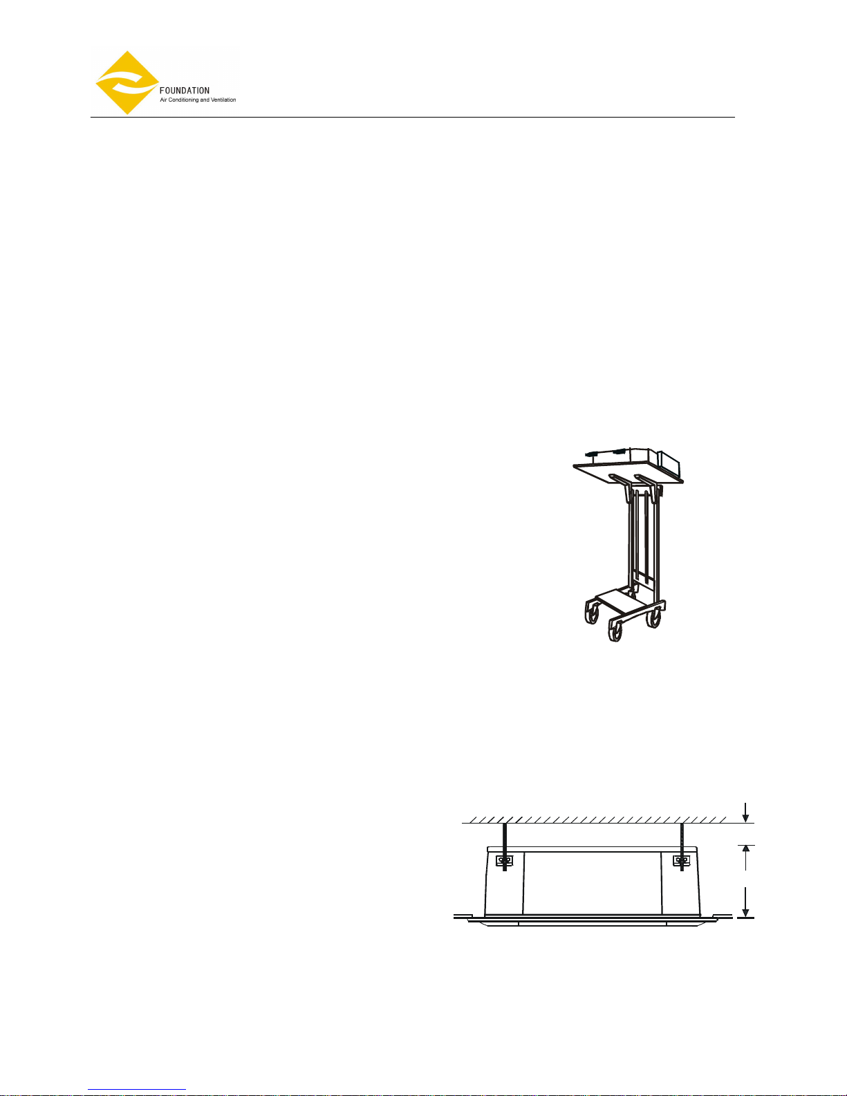
•
Installation of the unit should be facilitated by using a stacker and
inserting a plywood sheet between the unit and the elevated
stacker.(Fig.1)
• It is recommended to position the unit as centrally as possible in
the room to ensure optimum air distribution.
Generally the best louver position is the one which allows air
diffusion along the ceiling.
Alternatively intermediate positions can be selected.
• Check that it is possible to remove panels from ceiling in the
selected position, to allow enough clearance for maintenance and
servicing operations.
Install the unit in a position:
• Having sufficient strength to carry the weight of the
unit.
•
Where the inlet and outlet grilles are not obstructed
and the conditioned air is able to blow all over the
room.
• From where condensate can be easily run to drain.
• Check the distance between the upper slab and
false ceiling to ensure the unit will suit the distance.
See Fig.2. (Distance A 290 mm; distance B 10 mm
Page 16 of 49
Ceiling cassette
Fan
Coil Unit
, 4-pipe system
Model: FP-
KM
• Ensure there is sufficient space around the unit to service it. See Fig.3
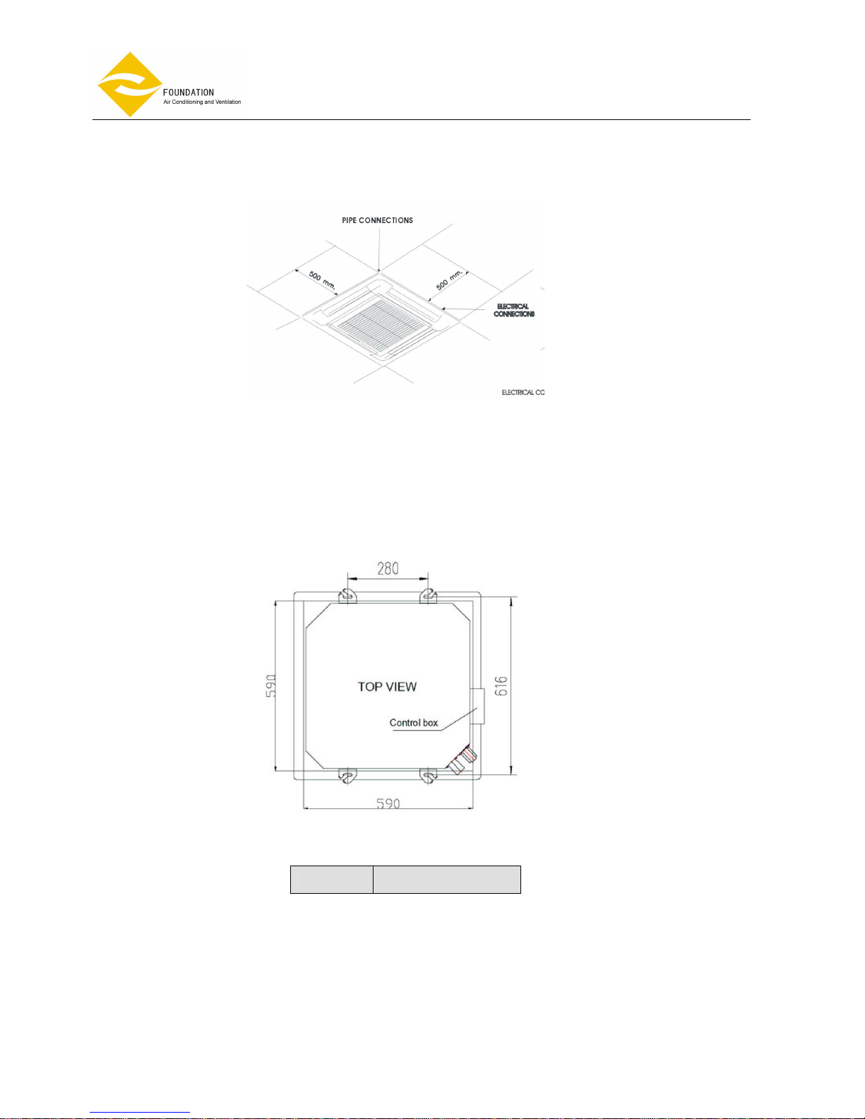
INSTALLATION METHOD
• Using the installation template open ceiling panels and install the suspension bolts as in Fig.4 below
590×590: Dimensions for opening
616×280: Suspension Bolts
MODELS
FP-68KM4
FP-80KM4
Fig.3
Page 17 of 49
Ceiling cassette
Fan
Coil Unit
, 4-pipe system
Model: FP-
KM
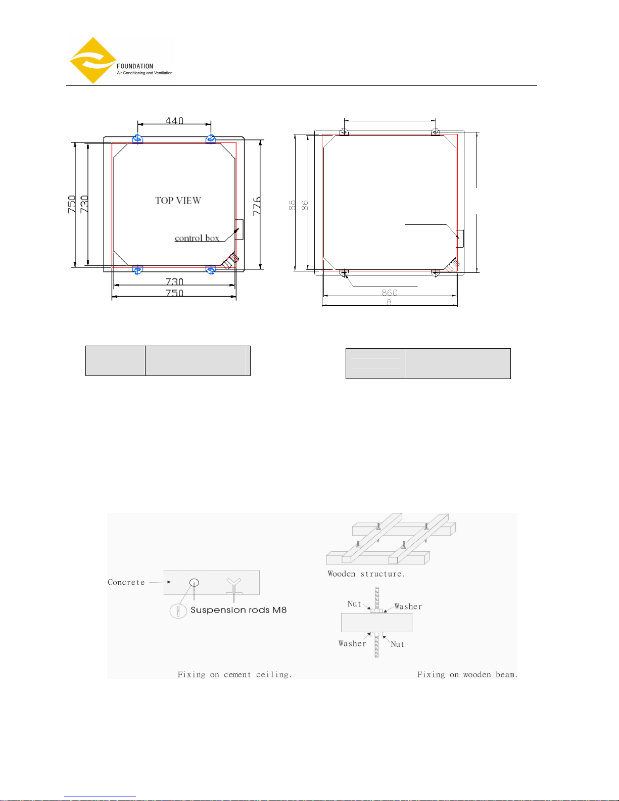
mounting brackets
control box
0
0
8 0
750×750: Dimensions for opening
440×776: Suspension Bolts
MODELS
FP- 85KM4
FP-102KM4
FP-136KM4
880× 880: Dimensions for opening
395× 880: Suspension Bolts
MODELS
FP-170KM4
FP-204KM4
FP-238KM4
• Mark position of suspension rods, water lines and condensate drain pipe, power supply cables and
remote control cable.
Supporting rods can be fixed, depending on the type of ceiling, as shown in Fig. 5 and Fig.6.
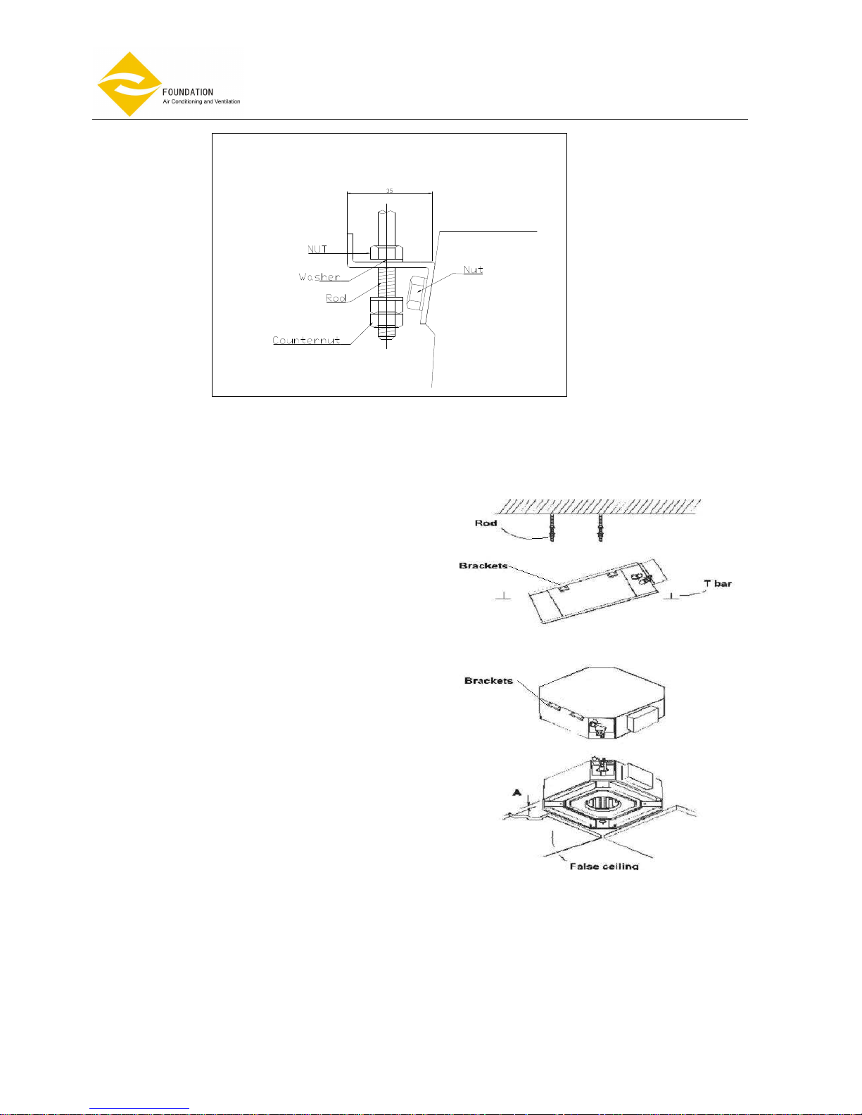
• Fit suspension brackets supplied with the unit to the threaded rods (Fig.7).
Do not tighten nuts and counter nuts; this operation has to be done only after final leveling of the unit,
when all the connections have been completed.
Fig. 4
Fig. 5 Fig. 6
395
Page 18 of 49
Ceiling cassette
Fan
Coil Unit
, 4-pipe system
Model: FP-
KM
• The spaces between the unit and ceiling can now be adjusted. Use the drop rods to make the adjustment.
• Check to ensure the unit is level. The drain will then automatically be lower than the rest of the drip tray.
• Tighten the nuts on the suspended rods.
Fig.7
• Ensure the ceiling is horizontally level,
otherwise condensate water cannot drain.
•
The casing is fixed to the slab with 4 drop rods.
The rods should have two nuts and washers to
lock the unit in position. The Cassette brackets
will then hook over the washers.
• When lifting the Cassette into position care
should be taken not to lift the unit by the drip
tray, which could be damaged.
• Lift unit (without the air panel) with care by its
four corners only. Do not lift unit by the
condensate drain discharge pipe or by the
piping connections.
• Incline unit (Fig.8, Fig.9) and insert it into the
false ceiling. Insert the rods into the bracket
slot.
With minimum height (see table) false ceilings,
it might be necessary to remove some T
brackets of the false ceiling temporarily.
• Using a
level guide, line up the unit with a spirit
level, and keep dimension between the body
and the lower part of the false ceiling (Fig.10).
• Line up the unit to the supporting bars of the
false ceiling tightening the nuts and counter
nuts of the threaded rods.
•
After connection of the condensate drain piping
and piping connections, check again that the
unit is level
Fig.8
Fig.10
Note: A = 3mm
Fig.9

Page 19 of 49
Ceiling cassette
Fan
Coil Unit
, 4-pipe system
Model: FP-
KM
DRAIN PIPE WORK
• The unit is fitted with a condensate pump with a 500
mm lift.
• The unit is provided with 22 mm. bore flexible hose
300 mm long.
• The flexible hose should be fitted into a 22 mm O/S
Φ. polyvinyl tube and sealed. The drain must be
installed with a downward slope.
• On completion the drain line should be insulated.
WATER CONNECTIONS
• Water connections are fixed to the unit body to avoid breaks when pipes are connected to valve
assemblies; it is advisable to tighten the connection with a spanner.
• The upper coil connection is supplied with air purge screw, the lower connection with water purge screw,
suitable for 8mm. wrench or screw-driver.
• Coil is partially drainable; it is advisable to blow air into the coil for complete drainage.
• Align the two (2) screw holes in the fixing plate to the two (2) holes in the external drain pan.
• Make sure the drain pan is horizontal.
• Tighten the two screws and making sure the external drain pan is installed flush with the fixing plate.
Fig. 11
Fig. 12
Fig. 13

Page 20 of 49
Ceiling cassette
Fan
Coil Unit
, 4-pipe system
Model: FP-
KM
When the installation is completed, it is necessary to wrap connecting pipe with insulation to prevent leakage to
ceiling tile.
INTER CONNECTING WIRING
We recommend that screened cable be used in electrically noisy areas.
1. Always separate low voltage (5VDC) signal wires from power line (230 VAC) to avoid electro-magnetic
disturbance of control system.
2. Do not install the unit where electromagnetic waves are directly radiated at the infrared receiver on the
unit.
3. Install the unit and components as far away as is practical (at least 5 meters) from the electromagnetic
wave source.
4. Where electromagnetic waves exist use shielded sensor cable.
5. Install a noise filter if any harmful noise exists in the power supply.
If the supply cord is damaged, it must be replaced by the manufacturer, its service agent or similarly qualified
person in order to avoid a hazard.
TERMINAL BLOCK
FP-68-80KM4
TERMINAL BLOCK
FP-102-136-160KM6
FP-85-102-136-170-204-238KM4
Fig. 14
Fig. 15
Fig. 16
Page 21 of 49
Ceiling cassette
Fan
Coil Unit
, 4-pipe system
Model: FP-
KM
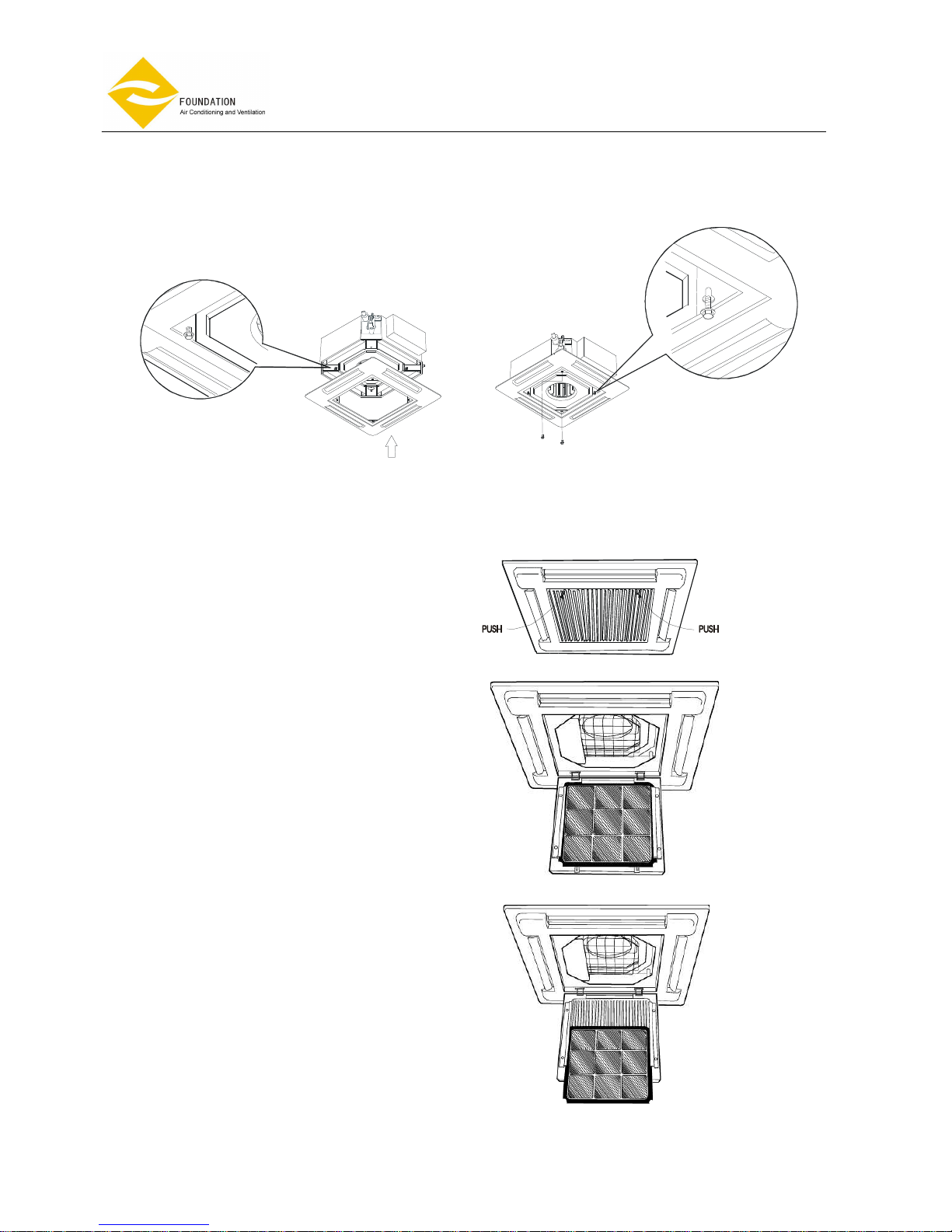
FILTER REMOVAL
• Unlock the two fasteners on the front panel.
• Open the grille downward with care.
• Pull the filter out along the slot.
• Clean the filter and reassemble.
MOUNTING FRONT PANEL ASSEMBLY
• Remove return grille from front panel.
• Move the front panel to casing.
• Tighten 4 screws as shown in Fig 17., 18.
Fig. 17
Fig. 18
Fig. 19

Page 22 of 49
Ceiling cassette
Fan
Coil Unit
, 4-pipe system
Model: FP-
KM
PRELIMINARY CHECKS BEFORE START-UP
• The unit should not be started up until the system piping has been cleaned and all the air has been purged.
• Check condensate drainpipe slope.
• Make sure that air filter is clean and properly installed.
• Ensure that voltage and current values correspond with the unit nameplate values; check electrical
connections.
• Verify that air outlets are not closed.
MAINTENANCE
• Before performing any service or maintenance operations, turn off the main power switch.
• The air filter is made of acrylic fiber and is washable in water. To remove filter simply open the intake grille by
releasing the two catches. See Fig.19 and the section filter removal.
• Check the filter periodically and before the operating season; clean or replace as necessary.
PROLONGED UNIT SHUT-DOWN
Prior to restarting the unit:
• Clean or replace the air filters.
• Check and remove any obstruction from the external drain pan and the internal drain pan.
EXTRA MAINTENANCE
• The electrical panel is easily accessible by removing the cover panel.
• The inspection or replacement of internal components such as; heat exchanger coil, condensate drain pump,
float switch, involves the removal of the condensate drain pan. See Fig.20-22.
• During the removal of the condensate drain pan protect the floor under the unit with a plastic sheet from
condensate water that could be spilled.
• Remove fixing screws of the drain pan fixture and remove condensate drain pan with care.
The appliance are intended to be maintained by qualified service personnel and installed at height not less than
2.5m.

Page 23 of 49
Ceiling cassette
Fan
Coil Unit
, 4-pipe system
Model: FP-
KM
Fig.22
Condensate Drain Pan Removal
Coil
Drain Pan
Drain Pan
Fixture
Fan blower Removal
Fan Blower
Fig.20 Fig.21
Condensate drain pan Removal

Page 24 of 49
Ceiling cassette
Fan
Coil Unit
, 4-pipe system
Model: FP-
KM
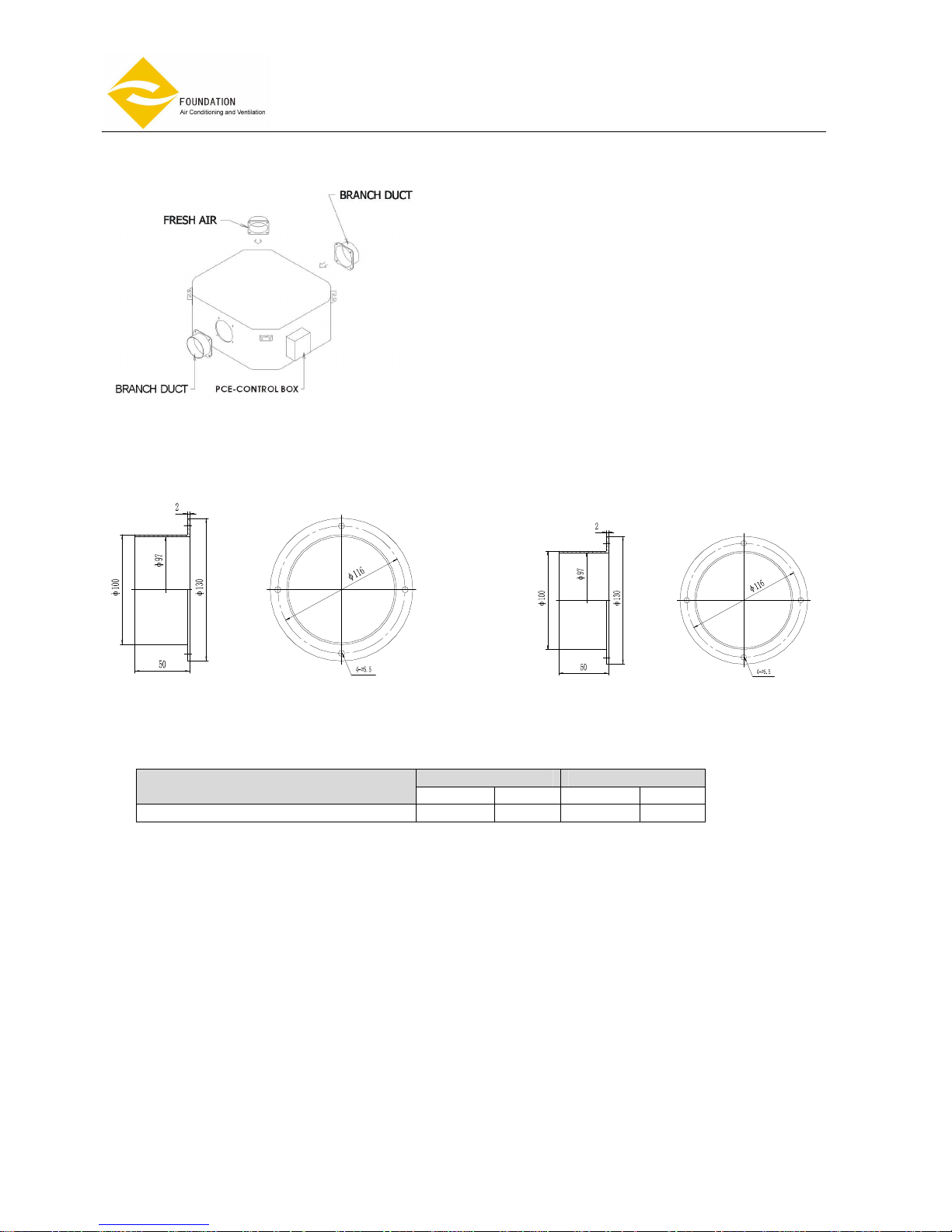
FRESH AIR RENEWAL AND BRANCH DUCTING
• The side opening allows separate ductwork to be installed for outside air intake and branch ducting. See
Fig.23
• Cut and remove anti-condensate insulating material.
• Install your flanges and conduits to casing. Conduit can be flexible polyester with spring core or corrugated
aluminium externally coated (dia.4 in.) with anti-condensate material (fiberglass 12-25 mm thickness).
Fresh air - There is one (1) opening for connecting a fresh air duct for FP-68-80-85-102-136-170-204-238 KM4
There are two (2) openings for connecting fresh air ducts for FP-102-136-160 KM6
Branch air – FP-68-80-85-102-136-170-204-238 KM4: Two(2) openings each.
FP-102-136-160 KM6: Four (4) openings each.
Order flanges (spigots) and blanking plates as accessories separately.
NOTE:
-
Branch duct flange (Optional part)
-
Fresh air duct flange (Optional part)
-
Blanking plate (Optional part)
Fig. 23
Fresh Air Flange
and Duct
Branch Air Flange
and Duct
Fig. 24

Page 25 of 49
Ceiling cassette
Fan
Coil Unit
, 4-pipe system
Model: FP-
KM
MODEL L S
FP-68-80KM4 570 570
FP-85-102-136KM4 730 730
FP-170-204-238KM4 860 860
Fig. 25
Page 26 of 49
Ceiling cassette
Fan
Coil Unit
, 4-pipe system
Model: FP-
KM
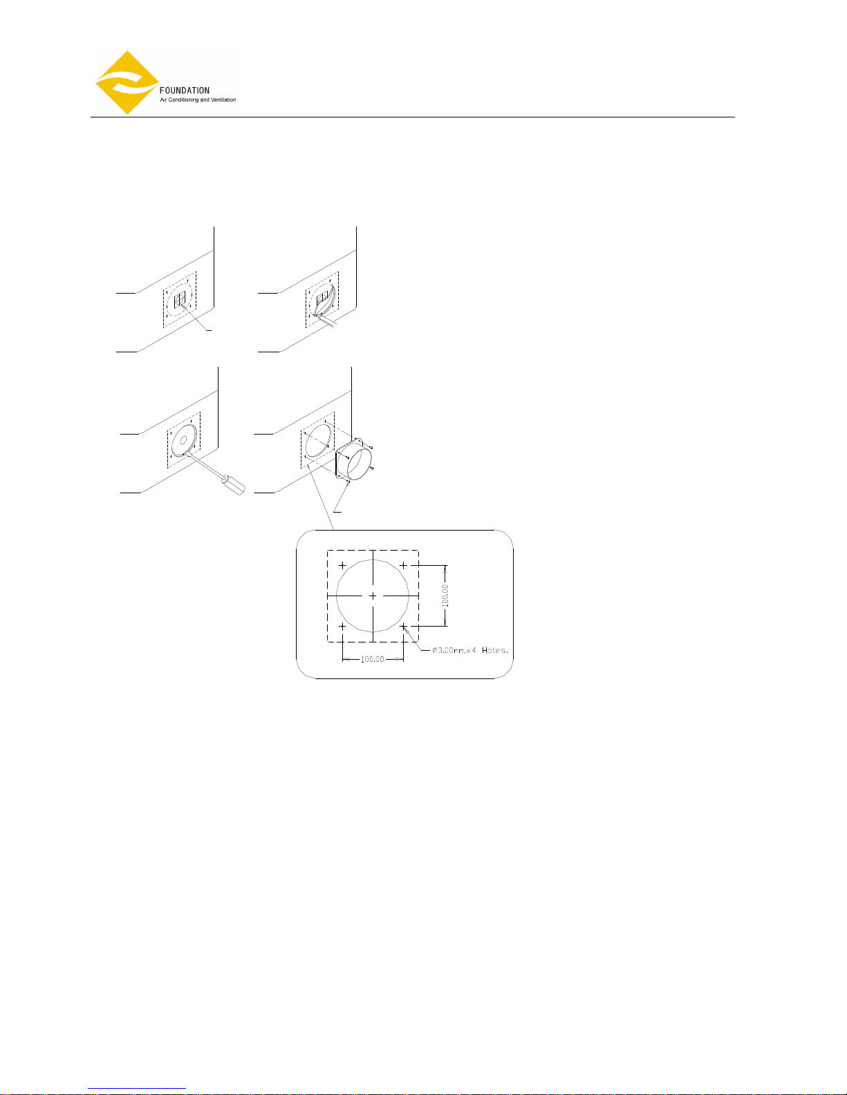
BRANCH DUCT AND FRESH AIR DUCT INSTALLATION
BRANCH DUCT FRESH AIR
MODEL
Dia(mm) QTY Dia.(mm) QTY
FP-68-80-85-102-136-170-204-238 KM4 100 2 100 1
Fig. 26
Fig. 27
Page 27 of 49
Ceiling cassette
Fan
Coil Unit
, 4-pipe system
Model: FP-
KM
BRANCH DUCT AND FRESH AIR DUCT POSITIONS
Step 1 Step 2
Step 3
Step 4
STICKER
Tapping Screw
Dia 3 mm.x12 mm.l.
1.
Look for the yellow sticker on the casing for
location of branch duct or fresh air intake
connections.
2. The sticker is at the center of a knock out
hole underneath the casing insulation. Use
a cutter and follow along the pre-cut
circular marking as shown and trim off the
insulation.
3. Knock out the pre-cut hole.
4. Connect the flange on to the opening with
D3 mm. x 12 mm. tapping screws.

Page 28 of 49
Ceiling cassette
Fan
Coil Unit
, 4-pipe system
Model: FP-
KM
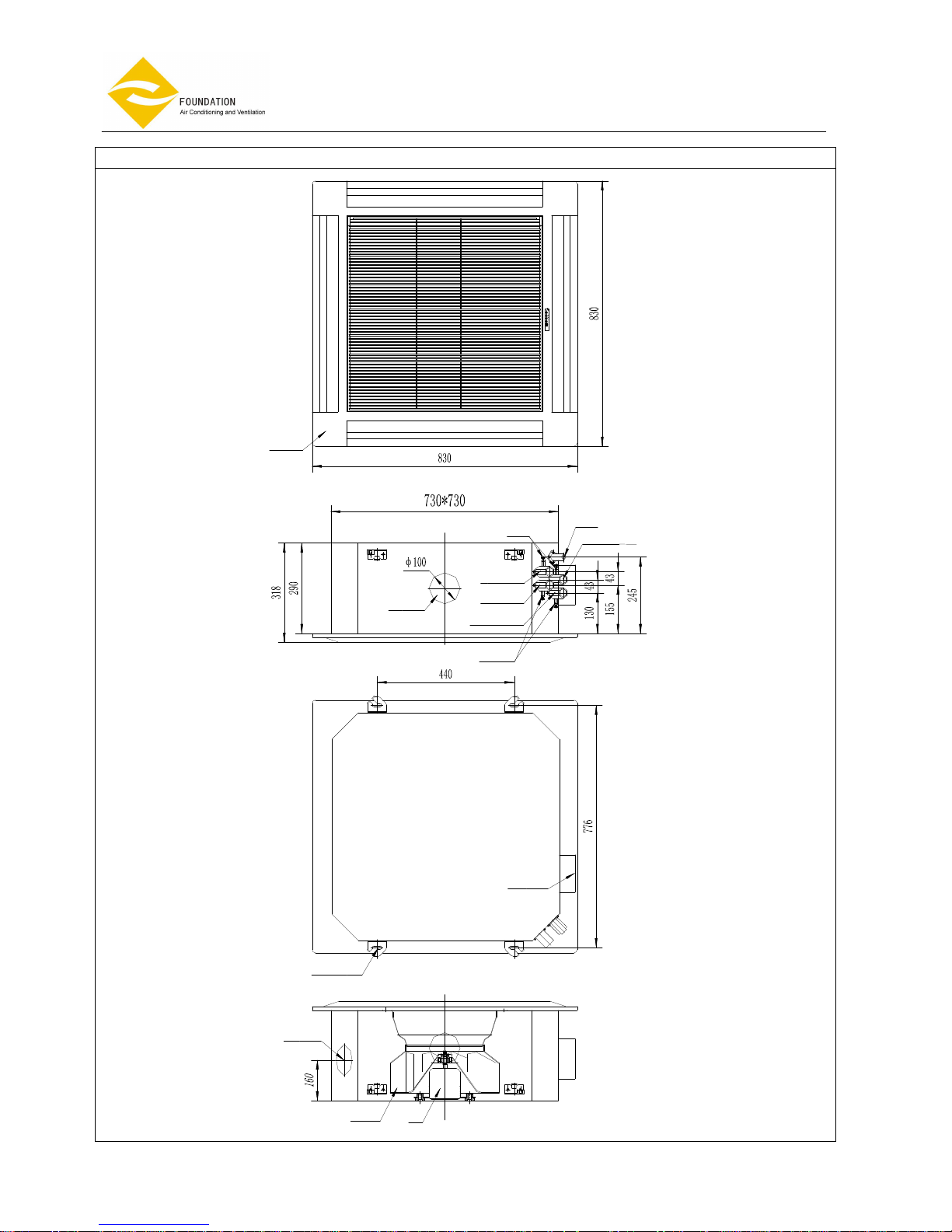
DIMENSIONAL DRAWINGS
FP-68-80KM4
FRESH AIR DUCT
MOTOR
PANEL COVER
BRANCH DUCT
CHILLED WATER INLET
FAN BLOWER
CONTROL BOX
WATER PURGE
HOT WATER OUTLET
HOT WATER INLET
AIR VENT
CHILLED WATER OUTLET
DRAINAGE
MOUNTING BRACKETS
Page 29 of 49
Ceiling cassette
Fan
Coil Unit
, 4-pipe system
Model: FP-
KM
FP-85-102-136KM4
MOUNTING BRACKETS
FRESH AIR DUCT
FAN BLOWER
MOTOR
PANEL COVER
FRESH AIR DUCT
TERMINAL BLOCK
WATER PURGE
HOT WATER OUTLET
HOT WATER INLET
CHILLED WATER INLET
AIR VENT
CHILLED WATER OUTLET
DRAINAGE

Page 30 of 49
Ceiling cassette
Fan
Coil Unit
, 4-pipe system
Model: FP-
KM
FP-170-204-238KM4
FRESH AIR DUCT
FAN BLOWER MOTOR
MOUNTING BRACKET
PANEL COVER
TERMINAL BLOCK
WATER PURGE
HOT WATER OUTLET
HOT WATER INLET
CHILLED WATER INLET
BRANCH DUCT
AIR VENT
CHILLED WATER OUTLET
DRAINAGE
Page 31 of 49
Ceiling cassette
Fan
Coil Unit
, 4-pipe system
Model: FP-
KM
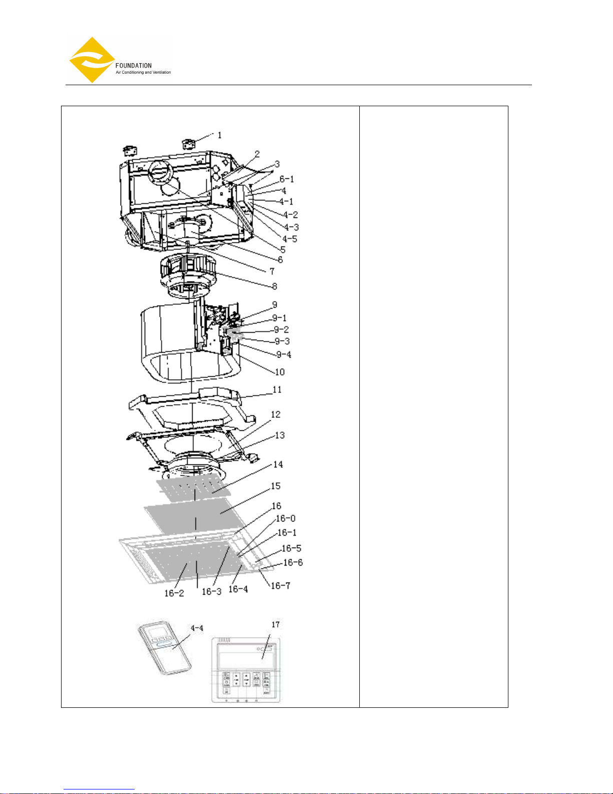
FP-68-80KM4
1-Mounting brackets
2-External drain pan
3-Load bearing structure
4-Control box
4-1- Main PCB
4-2-Transformer
4-3-Terminal block
4-4-Remote handset
4-5-Wire clip
5-Branch duct
6-Fan motor
6-1- motor capacitor
7- Fresh air outlet
8-Fan blower
9-Drain pump assembly
9-1- Drain pump fixture
9-2- Drain pump
9-3-Drainage tube
9-4- Float switch
10-Heat exchanger
11-Drain pan
12-Drain pan fixture
13-Venturi
14-Shield
15-Air filter
16-Cover panel
16-0- Receiver display
16-1-Receiver label sticker
16-2-Grille
16-3-Bolt(Left)
16-4-Bolt(Right)
16-5-Louver
16-6-Stepping motor
16-7-Fan bearing
17- Wire wall pad

Page 32 of 49
Ceiling cassette
Fan
Coil Unit
, 4-pipe system
Model: FP-
KM
FP-85-102-136KM4
1-Mounting brackets
2-External drain pan
3- Load bearing structure
4- Outside control box
4-1-Terminal Block
4-2-Invert board
4-3-Wire clip
5-Branch duct
6-Fresh air outlet
7-Fan motor
7-1-Fan motor capacitor
8-Fan blower
9-Drain pump assembly
9-1- Pump fixture
9-2-Drain pump
9-3-Drainage tube
9-4-Float switch
10-Heat exchanger
11-Drain pan
12-Venturi
13-Inside control box
13-1-Transformer
13-2-Main PCB
13-3- Remote handset
14-Inside control box cover
15- Shield
16-Air filter
17-Panel
17-0- Receiver display
17-1-Receiver label sticker
17-2-Grille
17-3-Bolt(Left)
17-4-Bolt(Right)
17-5-Louver
17-6-Stepping motor
17-7-Fan bearing
18- Wire wall pad

Page 33 of 49
Ceiling cassette
Fan
Coil Unit
, 4-pipe system
Model: FP-
KM
FP-170-204-238KM4
1-Mounting brackets
2-External drain pan
3- Load bearing structure
4- Outside control box
4-1-Terminal Block
4-2-Invert board
4-3-Wire clip
5-Branch duct
6-Fresh air outlet
7-Fan motor
7-1-fan motor capacitor
8-Fan blower
9--Drain pump assembly
9-1- Pump fixture
9-2-Drain pump
9-3-Drainage tube
9-4-Float switch
10-Heat exchanger
11-Drain pan
12-Venturi
13-Inside control box
13-1-Transformer
13-2-Main PCB
13-3- Remote handset
14-Inside control box cover
15- Shield
16-Air filter
17-Panel
17-0- Receiver display
17-1-Receiver label sticker
17-2-Grille
17-3-Bolt(Left)
17-4-Bolt(Right)
17-5-Louver
17-6-Stepping motor
17-7-Fan bearing
18- Wire wall pad

Page 34 of 49
Ceiling cassette
Fan
Coil Unit
, 4-pipe system
Model: FP-
KM
LCD DI SPLAY
Bett ery
RESET But t on
Press butt on t o r est art
r emote
Cl ock But t on
When you c hange t he
batt eri es, you must reset t he
cl ock ti me. Af t er you i nst al l
t he new bat ter i es , t he cl ock
t i me wi l l bl i nk. Then pr ess the
cl ock but t on , t he cl ock t i me
wi l l not bl i nk. Pr ess Ti mer -s et
but ton t o i ncrease t he t i me by 1
mi nut e st ep. At l ast pr ess the
cl ock but t on agai n.
Aut o
Ti mer -on
Fan s peed
Aut o Low-Med- Hi gh
Sl eep
Cool i ng
Arr ow di rect i on i s shown
f rom the fi r st f unct i on
t o the sec ond f unct i on.
AM
PM
A
A
AM
PM
℃
Dehumidify
Heat i ng
Fan
Fan But t on
Press but t on t o sel ect
l ow 、medi um、hi gh or Aut o
speed.
ON/OFF But t on
Press t hi s butt on wi l l turn t he
ai r- condi ti oni ng uni t on or of f .
Note: ON/OFF butt on wi l l not
wor k when conti nuous dai l y
oper at i on i s set .
Swi ng Butt on
Ai r di st ri butor i n al l
mode.
MODE But t on
Press but t on t o sel ect Auto mode
、Cool 、Dehumi di fy、 Fan or Heat .
Sl eep But t on
Sl eep mode wi l l aut omat i cal l y
adj ust t emper at ur e and save ener gy
when you ar e sl eepi ng.
Fan s peed
Reset
Cl ock
Ti mer- Set
Swi ng
Mode
AM
PM
Ti me-of f
Ti me-on Network
AM
PM
A
A
℃
Ti mer -of f Butt on
Press t he but t on once , t he
t i mer -of f i con wi l l bl i nk.
Then you pr es s TIMER butt on
t o set ti mer - off t i me by 10
mi nut es st ep. Pr ess the
but t on agai n, t i mer - off i s
set . Pr ess t he but t on agai n
, t i mer - off mode i s cancel l ed.
Ti mer -set t i ng But t on
When you set t he ti me cl ock , pr ess
but ton t o i ncr ease i n 1 mi nute st eps.
When you s et t he t i mer - on and
t i mer -of f , pr ess but t on t o i ncr ease by 10
mi nut es st ep.
Ti mer -of f
Cl ock i con
Si gnal sendi ng
Networ k
Swi ng
Set t emper at ur e
Ti mer -on But t on
Press t he but t on once , t he
t i mer -on i con wi l l bl i nk.
Then pr ess TI MER butt on t o
set t i mer -on t i me by 10
mi nut es st ep. Pr ess the
but t on agai n, t i mer - on i s set .
Press t he but t on agai n
, t i mer - on mode i s cancel l ed.
Network Butt on
You can set al l paramet er s on
mast er uni t. Then pr es s t he
butt on f or 3s , networ k i con wi l l
appear. Al l paramet er s have
been s ent to sl ave uni t s.
Up But t on
Press but t on t o i ncr eas t emper at ure 1℃
st ep. ( Max:30℃)
Down butt on
Press but t on t o decr ease t emper at ur e 1℃
st ep. (mi n:16℃)
Transmi ssi on source used f or
sendi ng cont r ol si gnal t o the
ai r- condi ti oni ng uni t
LCD DI SPLAY
P r e s s T i m e - S e t b u t t o n f o r
3 s , C y c l e i c o n w i l l a p p e a r . C y c l e
t i m e r - o n a n d t i m e r - o f f i s o n .
T h e n p r e s s t h e b u t t o n f o r a n o t h e r
3 s , c y c l e i c o n w i l l d i s a p p e a r .
C y c l e t i m e r - o n a n d t i m e r - o f f i s
o f f .
Cycl e ti mer - on
and t i mer -of f
REMOTE CONTROLLER

Page 35 of 49
Ceiling cassette
Fan
Coil Unit
, 4-pipe system
Model: FP-
KM
WIRED WALL PAD CONTROL (OPTIONAL)
ENTER
AM/ PM
℃
1--ON/OFF Button
Press the button, the unit will be turned on or off.
2--LED signal
3--Room temperature Sensor
4--Real time o'clock
5--Unit Number
No.00 is the master unit. You can set slave units(No.01--31)
parametres on the master wall pad.
6--Mode: Auto,Cool, Dehumidification, Ventilation and Heat
Auto mode Cool mode
Dehumidification Ventilation mode Heat mode
7
- -
Setting Time
8--Timer ON and OFF
Cycle Timer Timer ON Timer OFF
9--Error Mark
01_ Room temperature sensor is damaged;
02_ Drainage system is damaged;
03_ Coil temperature sensor is damaged;
04_ Auto restart function is damaged.
05_ Outdoor coil temperature sensor is damaged;
06_ High or low pressure switch is opened;
08_ The unit is shortage of refrigerant.
10--Error Alarm
11--Room temperature
12--Setting temperature
13----Fan Speed Icon: Auto,Low,Medium and High
14----Sleep Mode Icon
15----Louver Swing Icon
16----Communication Icon
17----Connecttion check Icon
18----Mode Select Button
Press the button to select Auto, cool, dehumidification,
ventilation or heat mode.
19----Fan Speed Select Button
Press the button to select Auto,low,medium or high
speed.
20----Sleep Mode Button.
It will automatically adjust temperature and save
energy when you are sleeping in cool mode or heat mode.
If the wall pad is the master,press it for 3s,commumication
icon appears, you can select slave unit from 1 to 31 by pressing
Time up or down button,all parameters appear on the wall pad
will be sent to unit you selcted or all slave units when you press
Enter Button.
21----Timer ON/OFF Button
1) Press TIMER button, or appears in LCD;
2) Press TIME (up) or (down) to select TIMER ON or
TIMER OFF or SET;
3) If TIMER ON or TIMER OFF is selected. "h" and or
blink in LCD; Press the TIMER(up) or (down) to set time by 10
minutes step; Press the TIMER button to confirm it. Repeat step
2) and 3) to set TIMER OFF or ON;
4) After setting TIMER ON and OFF, Press the TIME (up)
or (down). When and SET appear in LCD, then press
TIMER button to confirm it. , and appear in LCD at
the same time. Then press ENTER button to confirm it.
5) When you cancel cycle timer on and off, press TIMER
button for 30s. disappears in LCD. When you cancel timer
on or/and off, press TIMER button first, then press the TIME
(up) or (down) to select SET only in LCD. Press the TIMER
button again, then cancel timer on or/and off.
22----Clock Button
Press it first, then press Time up or down button to set real
time o'clock
23----Enter Button
In order to avoid misoperation ,all setting(except ON/OFF
Button)is valid after pressing the button.
24----Time up/down
Press Timer ON/OFF Button or Clock Button first,then
press it to set timer time or clock time
25----Swing Button,
26----Temperature Up/Down Button
Press Up Button to increase temperature 1℃ step
(MAX:30℃)
Press Down Button to decrease temperature 1℃ step
(MIN:16℃)
UNIT NO.
FOR SETTING MASTER-SLAVE UNIT USING WALL PAD
1.Please see the back of wall pad. The unit No. can be set using dip switchs.
UNIT NO.
dip switches
UNIT NO.
UNIT NO.
h
dip switches dip switches dip switches

Page 36 of 49
Ceiling cassette
Fan
Coil Unit
, 4-pipe system
Model: FP-
KM
CONTROLS SPECIFICATION
WITH MOTORIZED VALVE, MASTER – SLAVE CONTROL,
AND COMPUTER MANAGEMENT SYSTEM CONTROL
1.0
1.01.0
1.0
ABBREVIATIONS
Ts = Setting temperature
Tr = Room air temperature sensor
Ti1 = Indoor coil temperature sensor for heating
Ti2 = Indoor coil temperature sensor for cooling
Aux1 = Auxiliary contact for heating
Aux2 = Auxiliary contact for cooling
MTV1 = Motorized valve for heating
MTV2 = Motorized valve for cooling
2.0
2.02.0
2.0
SYSTEM OPERATION
2.A MASTER AND SLAVE UNIT FUNCTION
The control board can be set either as a master unit or slave unit.
2.A.1 MASTER UNIT FUNCTION
• The master unit can send its parameters to the slave unit using remote handset or wired wall pad.
• The master unit setting parameters are Unit ON/OFF, Mode, Fan Speed, Set Temperature, Sleep
Function and Swing function.
2.A.2 SLAVE UNIT FUNCTION
• The slave unit runs according to master unit parameters.
• Every unit is allowed to change to locally desired setting using remote handset or wired wall pad.
2.A.3 MASTER – SLAVE INSTALLATION
• When using remote handset, for the master unit ensure the JP0 jumper is shorted and for the slave units
JP0 is opened before turning ON the main power supply.
• When using wired wall pad, JP0 jumper will not function. Unit with No.00 wall pad is master unit. Unit with
No.01—31 is slave unit. See wired wall pad function guide to see how to set wall pad Numbers.
• Connect master to slave units with shield wire. NOTE: Use 4-core cable and one to one configuration.
• When MAIN POWER SUPPLY is ON :
With motorized valve: the master unit will respond with 3 beeps.
the slave unit will respond with 1 beep.

Page 37 of 49
Ceiling cassette
Fan
Coil Unit
, 4-pipe system
Model: FP-
KM
• More than 1 masters are allowed in a group. Masters can control commutatively.
2.B COMPUTER MANAGEMENT SYSTEM
• You can connect a group of units to your computer management system through the RS-485 converter.
You need install the special software in your computer. The software can change the unit running
parameters and check the unit working parameters. Detailed information can be found in Appendix 1.
2.B AIR CONDITIONER ON/OFF
There are 3 ways to turn the system on or off:
• by programmable timer on the handset or wall pad controls.
• by ON/OFF button on the handset or wired wall pad.
• by manual control button on the air conditioner.
2.D POWER ON SETTING
• When power on signal is received by the air conditioner, the Mode, Fan Speed, Set Temperature and
Swing settings will be the same as the last handset settings before the last power off.
2.E COOL MODE
• If Tr >= Ts+1 °C, cool operation is activated. MTV2 is turned on. AUX2 is closed. Indoor fan runs at set
speed.
• If Tr <= Ts, cool operation is terminated. MTV2 is turned off. AUX2 is opened. Indoor fan runs at set
speed.
• The range of Ts is 16 to 30 °C
• Indoor fan speed can be adjusted for low, medium, high and auto.
• When turned on, MTV2 requires 30 seconds before it is fully open.
•
When turned off, MTV2 requires 120 seconds before it is fully closed.
•
When the unit is turned off, indoor fan will delay for 5 seconds before it is turned off.
2.E.1. Protection of indoor coil
• If Ti2 < 2 °C for 2 minutes, MTV2 is turned off. AUX2 is opened. If indoor fan is set for low speed, it will
run at medium speed. If it is set for medium or high speed, it will keep running at the same speed.
• When Ti2 ≥ 5 °C for 2 minutes, MTV2 is turned on. AUX2 is closed. Indoor fan runs at set speed.
2.F FAN MODE
• Indoor fan runs at the set speed while MTV1 and MTV2 is turned off. AUX1 and AUX2 are opened.
• Indoor fan speed can be adjusted for low, medium, high and auto.

Page 38 of 49
Ceiling cassette
Fan
Coil Unit
, 4-pipe system
Model: FP-
KM
2.G HEAT MODE
• If Tr <= Ts-1, heat operation is activated, MTV1 is turned on. AUX1 is closed. Indoor fan runs at the set
speed.
• If Tr>= Ts, heat operation is terminated, MTV1 is turned off. AUX1 is opened. Indoor fan runs at low fan
speed for 30 seconds and stops for 3 minutes repeatedly.
• The range of Ts is 16 to 30 °C.
• Indoor fan speed can be adjusted for low, medium, high and auto
• When turned on, MTV1 requires 30 seconds before it is fully open.
•
When turned off, MTV1 requires 120 seconds before it is fully closed.
2.G.1 Pre-Heat
• If Ti 1<= 32 °C, when MTV1 is on, indoor fan remains off and AUX1 is closed.
• If 32 °C < Ti1< 38 °C, when MTV1 is on, AUX1 is closed and indoor fan keeps original state.
• If Ti1 >= 38 °C, when MTV1 is on, AUX1 is closed and Indoor fan runs at set speed.
• If indoor coil temperature sensor is damages, pre-heat time is set for 2 minutes and Indoor fan runs at set
speed.
2.G.2 Post-Heat
• If Ti1 > 38 °C, when MTV1 is off, indoor fan remains on at set speed and AUX1 is opened.
• If 35 °C <= Ti1< =38 °C, when MTV1 is off, AUX1 is opened. Indoor fan keeps original state.
• If Ti1 < 35 °C, when MTV1 is off, AUX1 is opened. Indoor fan stops.
• If indoor coil temperature sensor is damages, post-heat time is set for 3 minutes with indoor fan running
at set speed.
2.G.3 Protection of indoor coil
• If Ti1 >= 75 °C, MTV1 is turned off, AUX1 is opened. Indoor fan runs at set speed.
• If Ti1 < 70°C, MTV1 is turned on, AUX1 is closed. Indoor fan runs at set speed.
• If indoor coil temperature sensor is damaged, the protection mode will become obsolete and the unit will
work as the pre-heat and post-heat set times.
2.H DEHUMIDIFICATION MODE
If Tr>= 25°C, MTV2 will be ON for 3 minutes and OFF for 4 minutes. MTV1 is off.
If 16 °C <= Ti< 25 °C, MTV2 will be ON for 3 minutes and OFF for 6 minutes. MTV1 is off.
If Tr <16°C, MTV2 will be turned off. MTV1 is off.
2.I AUTO MODE
• The cool and heat operation will be selected automatically depending on the Tr and Ts.
• If auto mode is in cool operation, the operation will only change to heat if Tr < Ts – 3.5 °C.
• If auto mode is in heat operation, the operation will only change to cool if Tr > Ts + 1.5 °C
• Cool and Heat options working under Auto mode are the same as those working under Non-Auto mode
shown as the following figure.
Page 39 of 49
Ceiling cassette
Fan
Coil Unit
, 4-pipe system
Model: FP-
KM
2.J AUXILIARY CONTACTS
• Cool and dehumidification mode (AUX2)
AUX2 is closed when MTV2 is on (in normal operation). AUX2 is opened when MTV2 is off or protection
of indoor coil is operating.
• Ventilation mode (AUX1 and AUX2)
AUX1 and AUX2 are opened when Indoor fan is on.
• Heat mode (AUX1)
AUX1 is closed when MTV1 is on (in normal operation). AUX1 is opened when MTV1 is off or protection
of indoor coil is operating.
2.K SLEEP FUNCTION
• Sleep function can only be set in cool or heat modes.
• In cool mode, after sleep function is set, the indoor fan will run at low speed and Ts will increase 2°C
during 2 hours.
• In heat mode, after sleep function is set, the indoor fan will run at auto fan mode and Ts will decrease 2°C
during 2 hours.
• Changing of operation mode will cancel sleep function
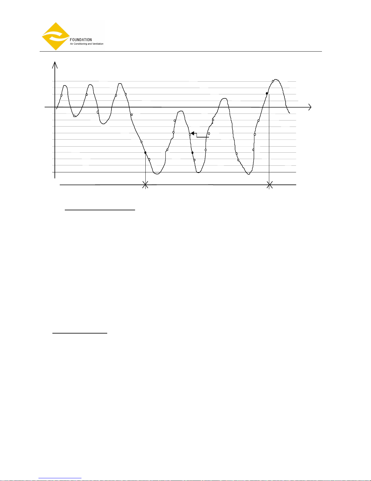
The COOL mode SLEEP profile is as follow:
+2
+1
Ts
-1
-2
-3
-4
-5
Tr
M
L
M
L
M
L
M
M
L
M
M
M
M
L
M
COOL MODE HEAT MODE COOL MODE
ALL MTVS &
AUXS OFF
MTV COLD &
AUX2 ON
MTV HOT &
AUX1 ON
ALL MTVS &
AUXS OFF
MTV HOT &
AUX1 ON
ALL MTVS &
AUXS OFF
MTV COLD &
AUX2 ON
MTV COLD &
AUX2 OFF
MTV HOT &
AUX1 OFF
MTV COLD &
AUX2 OFF
MTV HOT &
AUX1 OFF
H
H
L
H
H
M
ALL MTVS &
AUXS OFF

Page 40 of 49
Ceiling cassette
Fan
Coil Unit
, 4-pipe system
Model: FP-
KM
The HEAT mode SLEEP profile is as follows:
SLEEP set on
1/2
1 2
SLEEP set off
2
1
1/2
0
Ts-1
Ts-2
Hours since sleep set
t(hr)
Ts
Tr( ℃)
2.L AUTO FAN SPEED
• In cool mode, the auto fan speed will operate as the following diagram:
Fan speed:
H
M
L
ST ST+2
Tr ( ℃)
ST+3 ST+5
• In COOL mode, the fan speed cannot change until it has run at this speed over 30 seconds.
• In heat mode, the auto fan speed will operate as the following diagram:
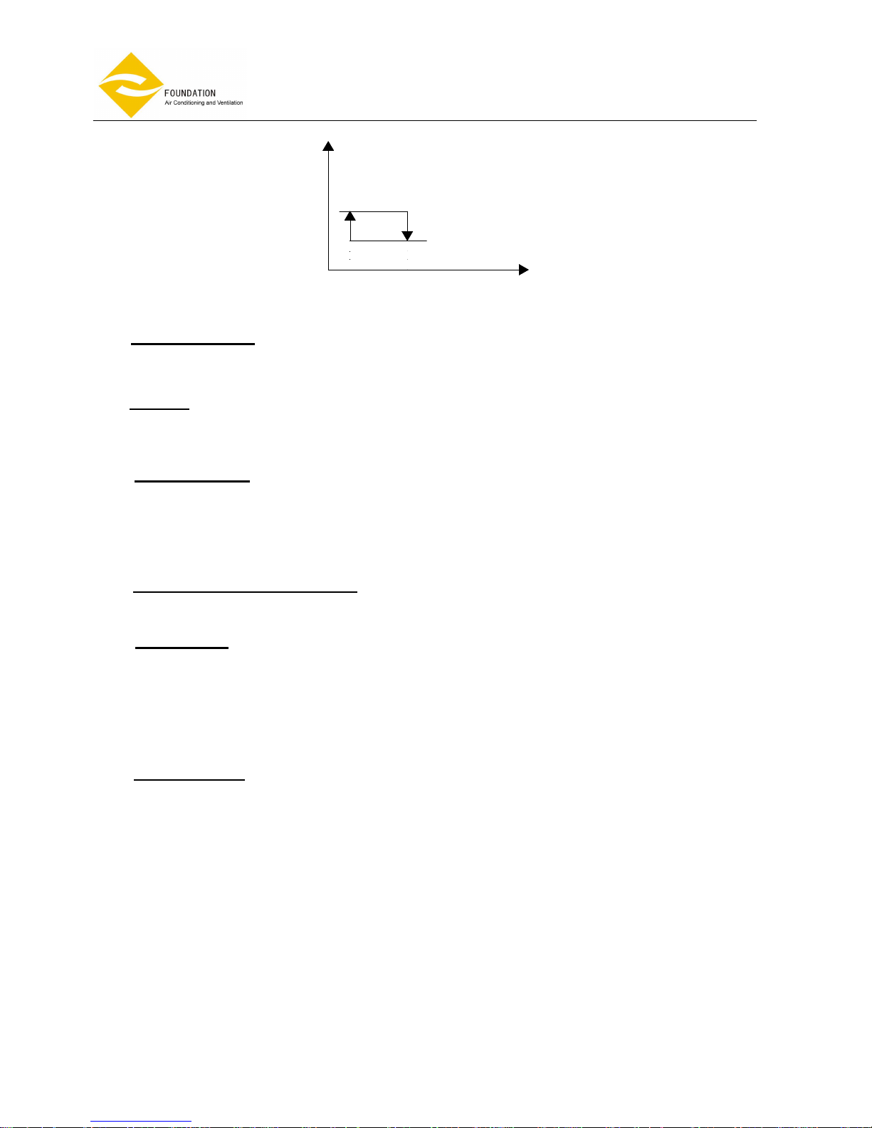
Page 41 of 49
Ceiling cassette
Fan
Coil Unit
, 4-pipe system
Model: FP-
KM
M
ST
L
ST+2
Fan speed:
Tr( ℃)
• In HEAT mode, the fan speed cannot change until it has run at this speed over 30 seconds.
2.M SWING / LOUVER
• If the indoor fan is operating, the louver will swing or can be stopped at a preferred location in any mode.
2.N BUZZER
• If a command is received by the air conditioner, the system will respond with a beep.
2.O AUTO RESTART
• The system uses non-volatile memory to save the present operation parameters when system is turned
off or in case of system failure or cessation of power supply. Operation parameters are mode, set
temperature, swing, and the fan speed. When power supply resumes or the system is switched on again,
the same operations as previously set will function.
2.P MANUAL OPERATION BUTTON
• On the unit front panel next to the LED lights is the reset button. Press it once and unit will operate
according to auto mode.
2.Q DRAIN PUMP
In cool and dehumidification mode :
- The drain pump will be turned on when the MTV2 is on, and will remain on for 5 minutes after the MTV
closed.
- The drain pump will keep running for 5 minutes after the mode is changed.
Warning ! If turn off the system by circuit breaker (or main power supply) the drain pump does not
work after turn off.
2.R FLOAT SWITCH
2.R.1 Float switch open before turning on.
When float switch(N/C) is opened before the breaker is on. MTV2 is off. Drain pump and indoor fan will operate. After
float switch is closed, MTV2 is on.
2.R.2 Float switch is opened, when unit is on.
If the float switch is opened, the drain pump will work. When the float switch is closed, the drain pump will run
continuously for 5 minutes.
If the float switch is opened for 5 minutes continuously, MTV2 will be turned off. Indoor fan runs at set speed.
If the float switch is opened for 10 minutes continuously, MTV2 will turn off. Indoor fan runs at set speed.
Red、yellow and green LED will blink with beeps.
2.R.3 Float switch is opened, when unit is off
If the float switch is opened, the drain pump will work. When the float switch is closed, the drain pump will run
continuously for 5 minutes.
If the float switch is opened for 10 minutes continuously, Red、yellow and green LED will blink. The drain
pump continues to work.

Page 42 of 49
Ceiling cassette
Fan
Coil Unit
, 4-pipe system
Model: FP-
KM
3.0
3.03.0
3.0
LED LIGHTS
ITEM RED LED YELLOW LED GREEN LED
High speed ON
Medium speed ON
Low speed ON
Pre-heat BLINK
Post-heat BLINK
Low temperature coil protection BLINK
Over heat indoor coil protection BLINK BLINK
Coil Temperature sensor damaged
ON BLINK
BLINK
Room Temperature sensor damaged
BLINK
BLINK
Condensate pump damaged
BLINK BLINK
BLINK
• If the sensor malfunctions, the red and yellow LED will blink with beep. Press reset button or any of the
remote handset buttons, and the beeping will stop.
• If the drain pump malfunctions, the red, yellow and green LED will blink with beeping sound. Press
reset button or any of the remote handset buttons, and the beeping will stop.
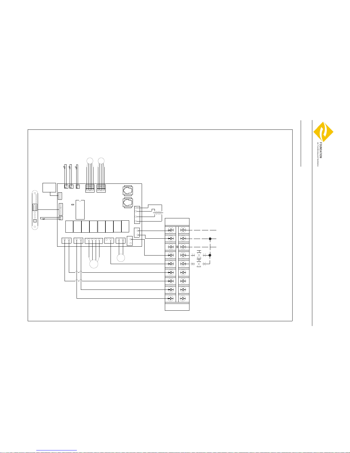
Page 43 of 49
Ceiling cassette
Fan
Coil Unit
, 4
-
pipe system
Model: FP-
KM
Wiring Diagrams
Water Cassette Wiring Diagram
PCE-06-08-PS
JP0
White
LOW
Red
Red
White
MED
HIGH
Brown
M
N
AUX1 AUX2
JP6
JP14
JP5
JPH
Wall Pad
JP10
JIPH
JP13
JIPC
JP11
JP7
JP9 JP8
SM3,4
SM1,2
Legend:
JP0----Short is master
Open is slave
JP1----Transformer
JP2----Power supply
JP3----2-way valve of Cooling
JP4----Drainage pump
JP5----Fan motor
JP6----Remote receiver
JP7----Stepping motor
JP8----Stepping motor
JP9----Stepping motor
JP10---Stepping motor
JP11---Room TEMP. sensor
JP13---Wall pad
JP14---Float switch
JPH----2-way valve of Heating
JIPH---Coil TEMP. sensor of Heating
JIPC---Coil TEMP. sensor of Cooling
AUX1---Auxiliary 1 for heat
AUX2---Auxiliary 2 for cool
T
A1
A2 A2
A1
Black
M
Yellow/Green
JP2
JP4
JP3
JP1
Black
Blue
N CV HV
L
TB
CPU
FP-68-80 KM4

Page 44 of 49
Ceiling cassette
Fan
Coil Unit
, 4
-
pipe system
Model: FP-
KM
Water Cassette Wiring Diagram
PCF-09-10-12-16-18-20-PS
N
L
CV HV A1
TB
Wall Pad
A2
A2
A1
T
JP2
Blue
Black
JP3
J
P
1
JP4
Black
M
JP5
M
N
HIGH
AUX2
LOW
Red
Red
MED
Brown
JPH
Yellow/Green
Legend:
JP0----Short is master
Open is slave
JP1----Transformer
JP2----Power supply
JP3----2-way valve of Cooling
JP4----Drainage pump
JP5----Fan motor
JP6----Remote receiver
JP7----Stepping motor
JP8----Stepping motor
JP9----Stepping motor
JP10---Stepping motor
JP11---Room TEMP. sensor
JP13---Wall pad
JP14---Float switch
JPH----2-way valve of Heating
JIPH---Coil TEMP. sensor of Heating
JIPC---Coil TEMP. sensor of Cooling
AUX1---Auxiliary 1 for heat
AUX2---Auxiliary 2 for cool
JP8
JP9JP10
JP0
JP7
JIPC
JP11
JP13
JIPH
JP14
JP6
White
SM3
、4
SM1
、2
H
M
L
A
U
X
1
White
CPU
FP-85-102-136-170-204-238 KM4

Page 45 of 49
Ceiling cassette
Fan
Coil Unit
, 4-pipe system
Model: FP-
KM
SHIELD WIRE
SHIELD WIRE
、4
、2、2
、4、4
、2
Water Cassette Wiring Diagrams
With Master and Slave Connection

Page 46 of 49
Ceiling cassette
Fan
Coil Unit
, 4-pipe system
Model: FP-
KM
SOLENOID VALVE (OPTIONAL)
The solenoid valve consists of a motor and a main body. The synchronous motor recovers by a spring and can be
controlled by a handle. The main body adopts the piston system.
1. Technical data of solenoid valve
Power supply: 230VAC50Hz
Input: 4W
Electric machine type: synchronous
Working pressure: 1.6Mpa
Ambient operating temperature: 0~650C
Liquid temperature range: 1~950C

Page 47 of 49
Ceiling cassette
Fan
Coil Unit
, 4-pipe system
Model: FP-
KM
2. Installation
A solenoid valve must be fitted to cut off water flow.
The choice and installation of components is the responsibility of the installer who should follow good working
practice and legislation in force in the country concerned.
Reference values
pH 6 – 8
Electrical conductivity Less than 200 mV/cm (25oC)
Chlorine ions Less than 50 ppm
Sulphuric acid ions Less than 50 ppm
Total iron Less than 0.3 ppm
Alkalinity M Less than 50 ppm
Total hardness Less than 35of
Sulpur ions none
Ammonia ions none
Silicon ions Less than 300 ppm
R3/4”WATER INLET AND OUTLET
2-WIRE 3-WAY VALVE----230V
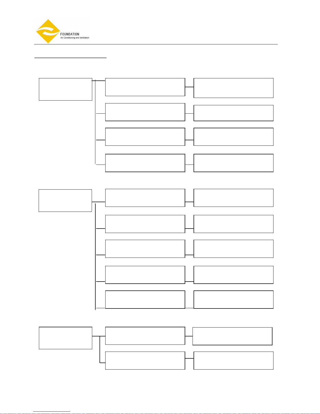
Page 48 of 49
Ceiling cassette
Fan
Coil Unit
, 4-pipe system
Model: FP-
KM
TROUBLE SHOOTING
MALFUNCTION CAUSE ACTION TO BE TAKEN
The fan coil does not
start up
No voltage
Mains switch in the “OFF position
Faulty room control
Faulty fan
Mash filter clogged
Air flow obstructed
Room control regulation
Incorrect water temperature
Air present
Insufficient output
- Check for presence of voltage
- Check fuse on board
- Place in the “ON” position
- Check the room control
- Check fan motor
- Clean the filter
- Remove obstacles
- Check
- Check
- Vent
Contact between metal parts
Loose screws
Noise and vibrations
- Check
- Tighten screws

Page 49 of 49
Ceiling cassette
Fan
Coil Unit
, 4-pipe system
Model: FP-
KM
APPENDIX1: CONTROL VIA COMPUTER
Centralizer For Fan Coil Unit (CFFCU) complex
Main features:
- Allows to control and to monitor via computer up to 256 fan coil units;
- By default fan coils can be divided in up to 8 zones. Possible to customize number of zones based on customer
requirement;
- Unit sequence in each zone can be set based on your requirement for easy monitoring;
- Working parameters and timer can be set to all units, each zone, or to individual unit;
- All fan coil units can be monitored in operation with their real running status;
- Can be checked Error status for any fan coil if there is such error;
- Can add-in fan coil easily in any sequence you like in future;
- Operating time of fan coil units can be set more precisely to optimize energy usage.
For example you may set your fan coil units to be on every working day from Monday till Friday, Cycle 1 with
Timer on 08:00 and timer off at 12:00, 12:00-13:00 lunch time is off, then Cycle 2 with Timer on 13:00 and timer
off at 17:00.
 Loading...