

Page 1
TPI Corporation
P.O. BOX 4973
JOHNSON CITY, TN 37602
www.tpicorp.com
Flat Panel Emitter Replacement Element Guide
For CH, MR and FHK Series
The at panel emitter is a total element replacement for metal sheath elements.
• All metal sheath elements and reectors are replaced by one complete unit including:
• The at panel emitter.
• All mounting hardware to convert the metal sheath elements to the at panel emitter.
• All hardware and components for power connection requirements.
• A heavy-duty wire guard for units that do not have one as standard equipment.
All at panel emitter replacement elements except (CH-4 and MR-4) come fully assembled and wired
for ease of eld conversion.
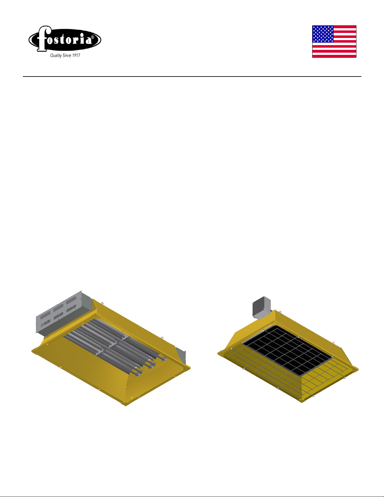
METAL SHEATH REPRESENTATION FLAT PANEL EMITTER REPRESENTATION
ISSUE DATE 7/2015 REV. DATE 9/28/2015 REV. LEVEL: 1 ECO 1-7107 OIPM P/N 8422 PG 1 OF 9
Page 2
Preparation of Existing CH or MR series For
installing Flat Panel Emitter
This procedure applies to all CH and MR series
metal sheath heaters.
ELECTRICAL SHOCK HAZARD
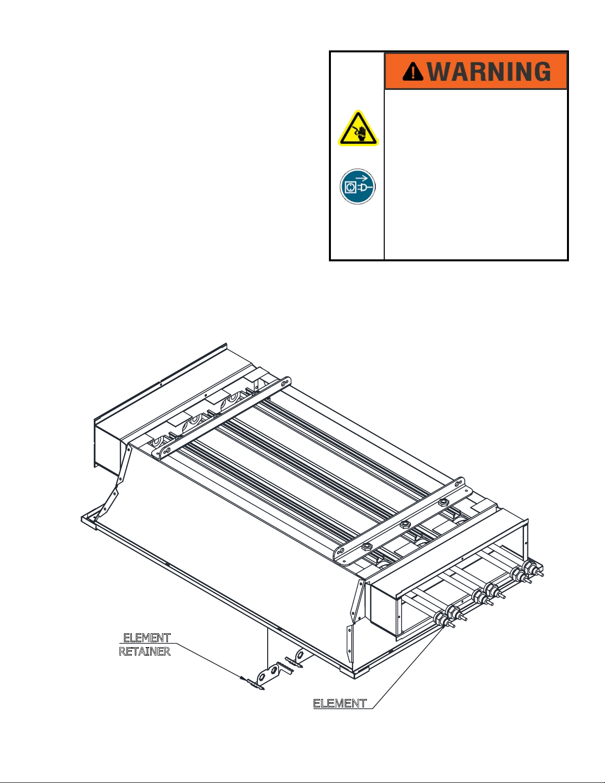
1. Remove existing u-shaped or straight metal
sheath elements and element retaining clips
from heater assembly. See Detail ‘A’.
2. Remove reector/extrusion assembly by
removing the 3/8” nuts on the back of the
mounting channel. See Detail ‘B’.
3. Remove the terminal box or boxes (2 on MR
series) by removing the sheet metal screws on
the inside of the housing. See Detail ‘C’.
DETAIL ‘A’
• Serious injury or death may
occur.
• Disconnect heaters from
electrical supply before
replacing parts.
ELEMENT
RETAINER
ELEMENT
ISSUE DATE 7/2015 REV. DATE 9/28/2015 REV. LEVEL: 1 ECO 1-7107 OIPM P/N 8422 PG 2 OF 9
Page 3
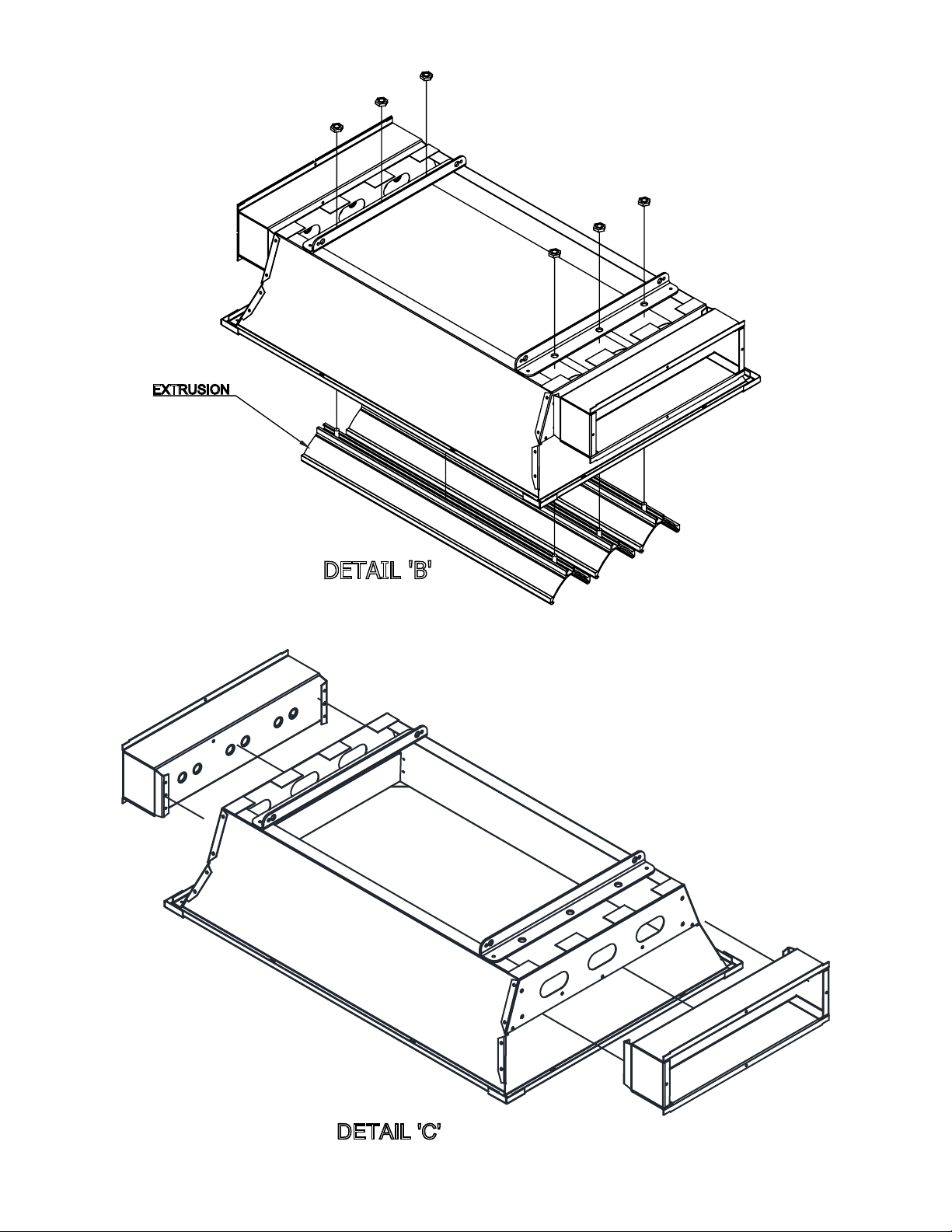
EXTRUSION
DETAIL 'B'
DETAIL 'C'
ISSUE DATE 7/2015 REV. DATE 9/28/2015 REV. LEVEL:1 ECO 1-7107 OIPM P/N 8422 PG 3 OF 9
Page 4
Installing the Flat Panel Emitter CH & MR-6,-13 AND 27
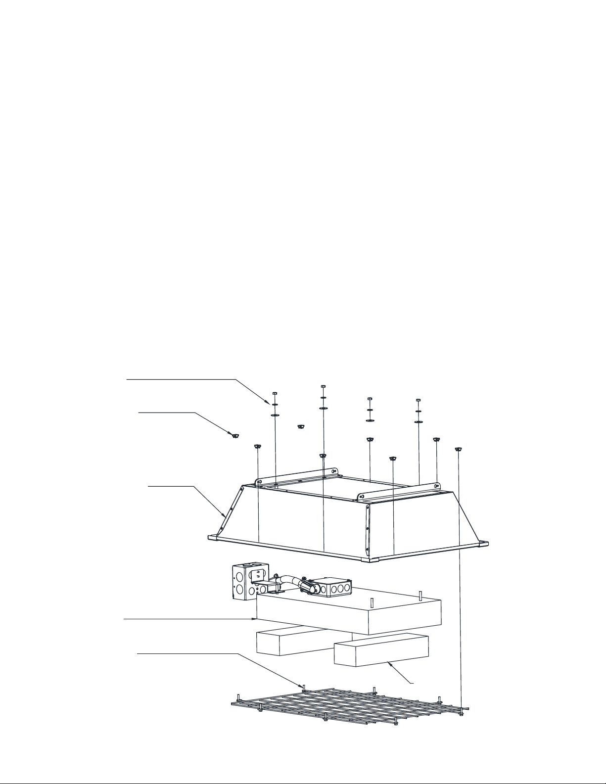
1. Install cage nuts into housing for grille attachment.
2. For ease of assembly, rest the element assembly on blocks high enough to allow the housing to set
down over the element assembly and not rest on the work surface. Be careful to not damage the
front of the Flat Panel Emitter.
3. Place the housing over the element assembly while feeding the conduit and connection box through
the housing.
4. Once the housing is in place, secure the housing and connection box bracket to the element
assembly with the hardware provided. Be sure to use a at washer and split washer on each
stud.
5. Mount the heavy duty wire guard to the front of the housing using the screws provided.
Note: The CH/MR-27 wire guard is a hinged sectional guard. The short section of
the wire guard should be positioned towards the center of the heater.
6. Hang the heater in the same manner as originally installed.
7. Wire heater as need referring to the wiring diagram on the front of the wiring box.
8. Restore power.
ELEMENT ASSEMBLY
MOUNTING HARDWARE
CAGE NUTS
HOUSING
GRILLE AND SCREWS
BLOCKING
ISSUE DATE 7/2015 REV. DATE 9/28/15 REV. LEVEL: 1 ECO 1-7107 OIPM P/N 8422 PG 4 OF 9
Page 5
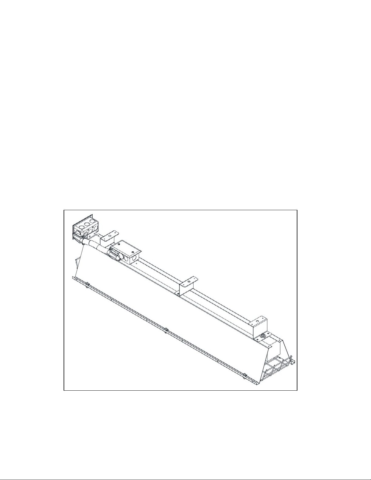
Installing the Flat Panel Emitter CH & MR-4
1. Remove extension ring from element assembly. This must be done to allow insertion between side
bafes.
2. For ease of assembly, rest the element assembly on blocks high enough to allow the housing to set
down over the element assembly and not rest on the work surface. Be careful to not damage the
front of the Flat Panel Emitter.
3. Place housing over the element assembly, mount the 2 x 4 outlet box and bracket over the mounting
stud and secure all to the housing with the hardware provided.
4. Attach lead wires to element termination with supplied hardware, making certain connections are
tight.
5. Replace extension ring on element assembly.
6. Connect conduit and connector to extension ring.
7. Feed lead wires through conduit and secure conduit to 2 x 4 outlet box.
8. Install cage nuts into housing for grille attachment.
9. Mount the heavy duty wire guard to the front of the housing using the screws provided.
10. Hang the heater in the same manner as originally installed.
11. Restore power.
Typical CH or MR-4 with Flat Panel Emitter
ISSUE DATE 7/2015 REV. DATE 9/28/15 REV. LEVEL: 1 ECO 1-7107 OIPM P/N 8422 PG 5 OF 9
Page 6
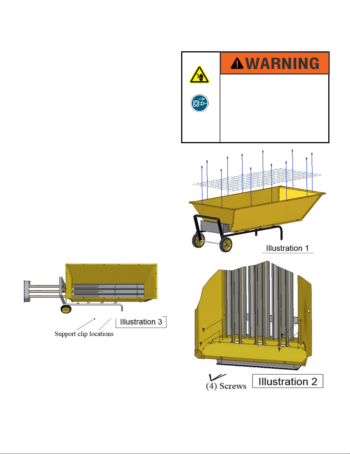
Preparation of Existing FHK-6 AND FHK-13
series For installing Flat Panel Emitter
1. DISCONNECT POWER FROM THE
ELECTRICAL SUPPLY CABLE OF
THE PORTABLE HEATER BEING
REPAIRED.
2. Position heater with reector opening pointing
U P.
3. Remove the wire guard from the heater to
access the fasteners that attach the terminal
box. Remove and save the (12) screws shown
in Illustration 1 with a 5/16” nut driver.
4. Remove and discard the (4) screws that
attach the terminal box to the heater,
with a 1/4” nut driver. See Illustration 2.
5. Grasp terminal box assembly and rmly pull
in the direction shown in Illustration 3.
The
elements have been fed through some
support clips inside the heater housing.
These clips will cause some drag or resistance
to removal.
There will be some unpleasant
noise as the elements slide through the clips.
6. Discard all.
ELECTRICAL SHOCK HAZARD
• Serious injury or death may
occur.
• Disconnect heaters from electrical
supply before replacing parts.
ISSUE DATE 7/2015 REV. DATE 9/28/2015 REV. LEVEL: 1 ECO 1-7107 OIPM P/N 8422 PG 6 OF 9
Page 7
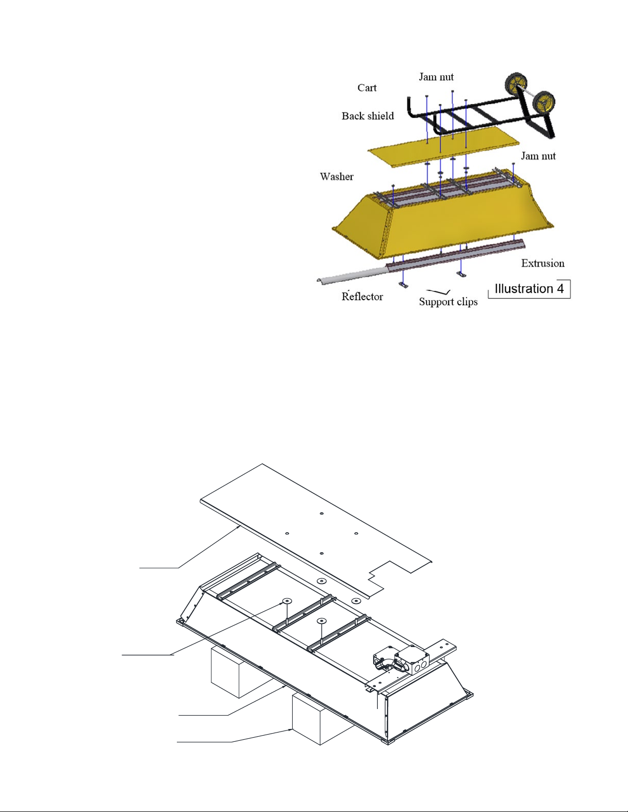
REMOVING REFLECTORS AND EXTRUSION
To remove the reector and extrusion :
1. Lay heater face down and remove the cart
from the heater by taking off the (4) jam nuts
as shown in Illustration 4.
2. Lift the back shield and (4) washers off the
heater.
3. Remove the (2) support clips from the front
of the reector.
4. Remove (4) jam nuts that secure the
extrusion to the housing. The extrusion
and reector will now come out of the
housing.
5. Discard all.
6. The housing is now ready for installation of
the Flat Panel Emitter.
INSTALLING THE FLAT PANEL EMITTER
1. For ease of assembly, rest the element assembly on blocks high enough to allow the housing to
set down over the element assembly and not rest on the work surface. Be careful to not damage
the front of the Flat Panel Emitter.
2. Place the housing over the element assembly while feeding the conduit , connection box and
mounting bracket through the housing.
3. Install the (4) washers and back shield as shown in Illustration 5.
ILLUSTRATION 5
BACK
SHIELD
WASHERS
HOUSING
BLOCKING
ISSUE DATE 7/2015 REV. DATE 9/28/2015 REV. LEVEL: 1 ECO 1-7107 OIPM P/N 8422 PG 7 OF 9
Page 8
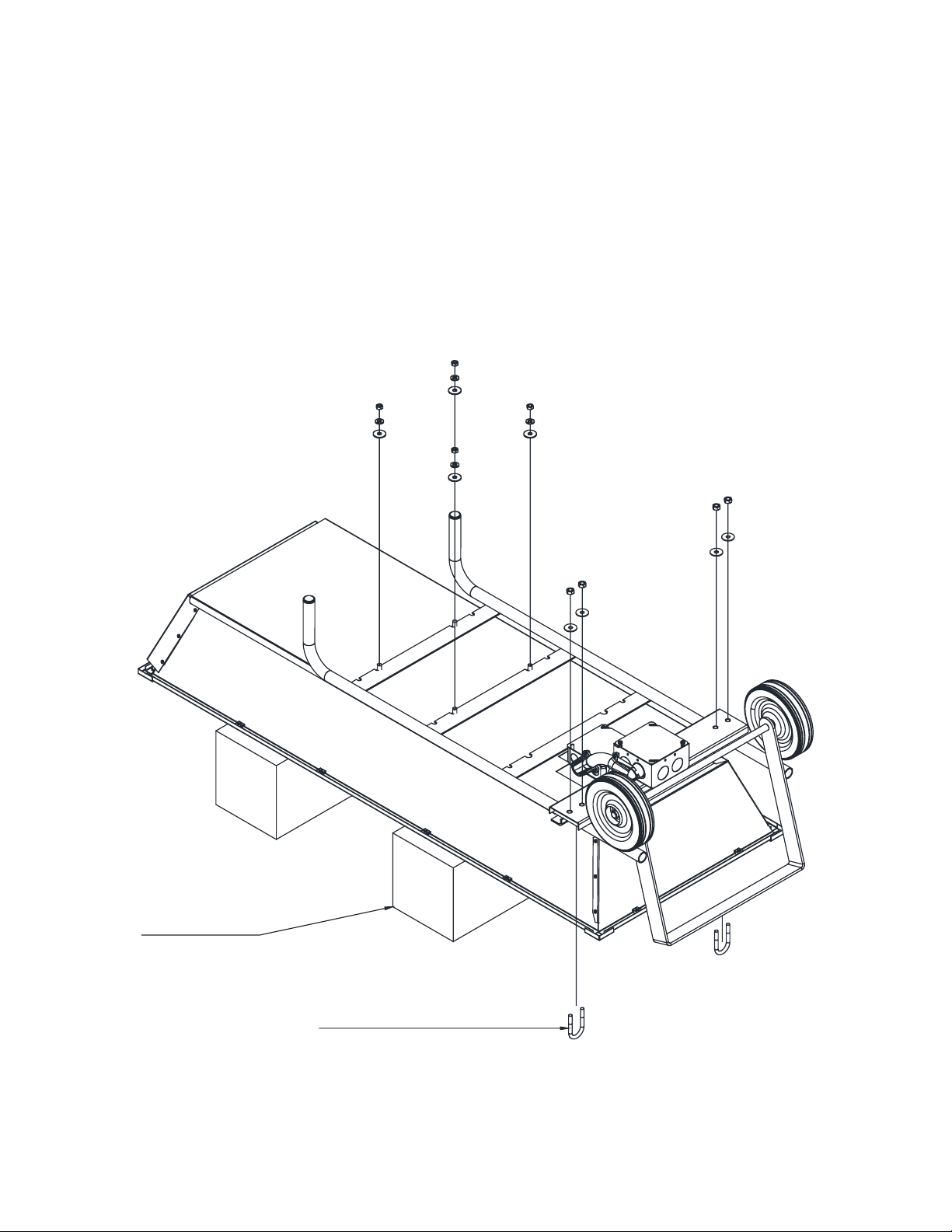
4. Re-install cart assembly as shown in Illustration 6. Be sure that the connection box and mounting
bracket are on the back side of the cart.
provided. Secure the mounting bracket to the cart frame using the u-bolts and 5/16” nuts and
washers.
Secure the cart to the housing using the 1/4” hardware
BLOCKING
U-BOLT
ILLUSTRATION 6
ISSUE DATE 7/2015 REV. DATE 9/28/2015 REV. LEVEL: 1 ECO 1-7107 OIPM P/N 8422 PG 8 OF 9
Page 9
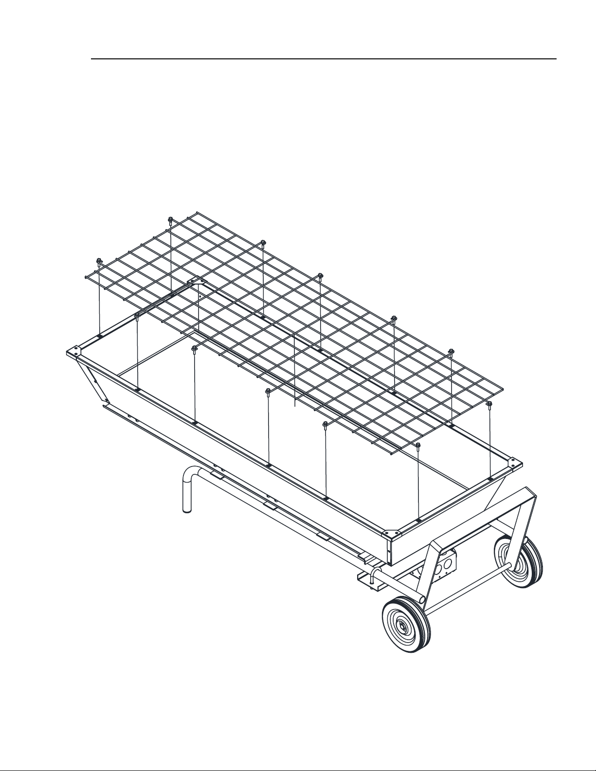
5.
After installing the cart, turn the complete assembly over and install the wire guard using the original
screws.
6.
Install cable or conduit as previously used on the heater. For additional wiring space, an
DO NOT OPERATE ANY FSP-SERIES WITHOUT THE WIRE GUARD INSTALLED.
extension ring may be used on the connection box.
7. Restore power.
ISSUE DATE 7/2015 REV. DATE 9/28/2015 REV. LEVEL: 1 ECO 1-7107 OIPM P/N 8422 PG 9 OF 9
 Loading...