

Page 1
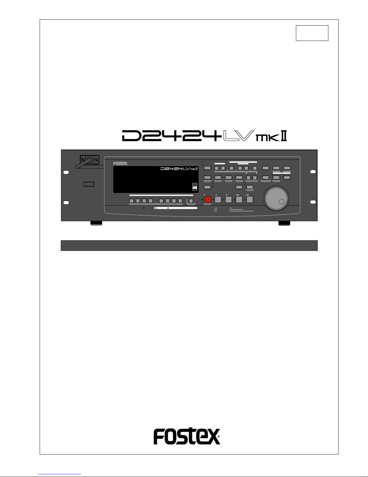
Reference Manual
24 Track Digital Recorder
Model
8289 651 000
(487245)
Introduction
Thank you for purchasing the Fostex D2424LVmkII.
The D2424LVmkII is a digital recorder using a 3.5 inch E-IDE hard disk recording media for recording/playback/editing in 24 real tracks plus 32 additional tracks.
In addition to non-compression recording at quantization 16 bit/44.1kHz or 48kHz, 24 bit/44.1kHz
or 48kHz, 24 bit/88.2kHz or 96kHz, the D2424LVmkII is also equipped with adat input/output (by
switching from S/P DIF).
Besides analog simultaneous record/playback, because it also complies with digital recording (S/P
DIF or adat) using DATA input/output and simultaneous recording of analog input plus digital input
(S/P DIF or adat), a full digital recording system can be built by combining the D2424LVmkII with
various digital mixers.
Song data of the D2424LVmkII can be saved as an adat or S/P DIF digital signal, as well as can be
backed up to the pre-installed CF drive as an FDMS-3 Ver. 3.0 or WAV file at high speed.
You can also use the optional E-IDE hard disk drive instead of the pre-installed CF drive for high
speed backup of an FDMS-3 Ver. 3.0 or WAV file.
For optional units, Model 8346 TC/SYNC card is available and these will also comply to phasing of
the standard feature WORD clock and also phasing against slave control by external LTC and VIDEO
reference signals.
Please carefully read through this manual together with the separate "Quick Operation Guide" for long
and satisfying operation of this equipment.
POWER
HOLD
RECORD
STOP
PLAY
REW
F FWD
ALL INPUT
ALL READY
LOCATE REC END
VARI PITCH
PUNCH
LOCATE
REHEARSAL
TAKE
RECALL
STORE
EXIT/NO
EXECUTE/YES
PGM SEL
NEXT
PREV
UNDO/REDO
PREVIEW
EDIT SETUP
AUTO RTN
OUTIN
AUTO PLAY
START
OUTIN
END
17-24
ACCESS
9-16
1/9/17
2/10/18
3/11/19
4/12/20 5/13/21 6/14/22 7/15/23
8/16/24
FOOT SW
LOCATE ABS 0
CLIPBOARD PLAY
AUTO
TRACK SHIFT
SHIFT
DISP SEL
CHARACTER
TIME BASE SEL
P.EDIT
EJECT
ENVELOPE
CHASE
TC READY TC GEN M.UNDO
TRACK SHIFT
PREV TC
NEXT TC
RECORD TRACK
CLIPBOARD
AUTO PUNCH
AUTO RTN
LOCATE MEMORY
24bit
96kHz
OPTICAL
24TRACK DIGITAL RECORDER
Page 2

Model D2424LVmkII Reference Manual (Safety Instruction/Contents)
2
12. Power Cord Protection - Power supply cords should be routed
so that they are not likely to be walked on or pinched by items
placed upon or against them, paying particular attention to cords
at plugs, convenience receptacles, and the point where they
exit from the appliance.
13. Cleaning - The appliance should be cleaned only as
recommended by the manufacturer.
14. Nonuse Periods - The power cord of the appliance should be
unplugged from the outlet when left unused for a long period of
time.
15. Object and Liquid Entry - Care should be taken so that objects
do not fall and liquids are not spilled into the enclosure through
openings.
16. Damage Requiring Service - The appliance should be serviced
by qualified service personnel when:
A. The power supply cord or the plug has been damaged; or
B. Objects have fallen, or liquid has been spilled into the appliance;
or
C. The appliance has been exposed to rain; or
D. The appliance does not appear to operate normally or exhibits a
marked change in performance; or
E. The appliance has been dropped, or the enclosure damaged.
17. Servicing - The user should not attempt to service the appliance
beyond that described in the operating instructions.
All other servicing should be referred to qualified service
personnel.
18. The appliance should be situated away from drops of water or
spray of water.
19. Objects containing liquid such as vase must not be put on the
appliance.
20. The appliance is not completely isolated from the power supply
even if the power switch is at off position.
21. Apparatus shall not be exposed to dripping or splashing and no
objects filled with liquids, such as vases, shall be placed on the
apparatus.
22. Only use attachments/accessories specified by the manufacturer.
23. An appliance with a protective earth terminal should be connected
to a mains outlet with a protective earth connection.
24. An appliance should be placed in a position where an AC plug /
inlet can be easily pulled out by hand.
25. Main plug is used as the disconnection device. It shall remain
readily operable and should not be obstructed during intended
use. To be completely disconnected the apparatus from supply
mains, the mains plug of the apparatus shall be disconnected
from the mains socket outlet completely.
The lightning flash with arrowhead symbol, within an
equilateral triangle, is intended to alert the user to the
presence of uninsulated "dangerous voltage" within the
product's enclosure that may be of sufficient magnitude
to constitute a risk of electric shock to persons.
The exclamation point within an equilateral triangle is
intended to alert the user to the presence of important
operating and maintenance (servicing) instructions in the
literature accompanying the appliance.
An appliance and cart combination should be moved with care.
Quick stops, excessive force, and uneven surfaces may cause
the appliance and cart combination to overturn.
7. Wall or Ceiling Mounting - The appliance should be mounted to
a wall or ceiling only as recommended by the manufacturer.
8. Ventilation - The appliance should be situated so that its location
or position dose not interfere with its proper ventilation.
For example, the appliance should not be situated on a bed,
sofa, rug, or similar surface that may block the ventilation
openings; or, placed in a built-in installation, such as a bookcase
or cabinet that may impede the flow of air through the ventilation
openings.
9. Heat - The appliance should be situated away from heat sources
such as radiators, heat registers, stoves, or other appliances
(including amplifiers) that produce heat.
10. Power Sources - The appliance should be connected to a power
supply only of the type described in the operating instructions or
as marked on the appliance.
11. Grounding or Polarization - The precautions that should be taken
so that the grounding or polarization means of an appliance is
not defeated.
"WARNING"
"TO REDUCE THE RISK OF FIRE OR ELECTRIC SHOCK,
DO NOT EXPOSE THIS APPLIANCE TO RAIN OR
MOISTURE."
SAFETY INSTRUCTIONS
1. Read Instructions - All the safety and operating instructions
should be read before the appliance is operated.
2. Retain Instructions - The safety and operating instructions
should be retained for future reference.
3. Heed Warnings - All warnings on the appliance and in the
operating instructions should be adhered to.
4. Follow Instructions - All operating and use instructions should
be followed.
5. Water and Moisture - The appliance should not be used near
water - for example, near a bathtub, washbowl, kitchen sink,
laundry tub, in a wet basement, or near a swimming pool, and
the like.
6. Carts and Stands - The appliance should be used only with a
cart or stand that is recommended by the manufacturer.
CAUTION: TO REDUCE THE RISK OF ELECTRIC SHOCK,
DO NOT REMOVE COVER (OR BACK).
NO USER - SERVICEABLE PARTS INSIDE.
REFER SERVICING TO QUALIFIED SERVICE PERSONNEL.
CAUTION
RISK OF ELECTRIC SHOCK
DO NOT OPEN
CAUTION:
TO PREVENT ELECTRIC SHOCK, MATCH WIDE BLADE OF
PLUG TO WIDE SLOT, FULLY INSERT.
ATTENTION:
POUR EVITER LES CHOCS ELECTRIQUES, INTRODUIRE
LA LAME LA PLUS LARGE DE LA FICHE DANS LA BORNE
CORRESPONDANTE DE LA PRISE ET POUSSER JUSQU'
AU FOND.
Page 3

Model D2424LVmkII Reference Manual (Safety Instruction/Contents)
3
Important Safety Instructions
1) Read these instructions.
2) Keep these instructions.
3) Heed all warnings.
4) Follow all instructions.
5) Do not use this apparatus near water.
6) Clean only with dry cloth.
7) Do not block any ventilation openings.
Install in accordance with the
manufacturer's instructions.
8) Do not install near any heat sources such
as radiators, heat registers, stoves, or
other apparatus (including amplifiers) that
produce heat.
9) Do not defeat the safety purpose of the
polarized or grounding-type plug.
A polarized plug has two blades with one
wider than the other. A grounding type
plug has two blades and a third grounding
prong. The wide blade or the third prong
are provided for your safety.
If the provided plug does not fit into your
outlet, consult an electrician for
replacement of the obsolete outlet.
10) Protect the power cord from being walked
on or pinched particularly at plugs,
convenience receptacles, and the point
where they exit from the apparatus.
11) Only use attachments/accessories
specified by the manufacturer.
12) Use only with the cart, stand, tripod,
bracket, or table specified by the
manufacturer, or sold with the apparatus.
When a cart is used, use caution when
moving the cart/apparatus combination
to avoid injury from tip-over.
13) Unplug this apparatus during lightning
storms or when unused for long periods
of time.
14) Refer all servicing to qualified service
personnel. Servicing is required when the
apparatus has been damaged in any
way, such as power-supply cord or plug
is damaged, liquid has been spilled or
objects have fallen into the apparatus, the
apparatus has been exposed to rain or
moisture, does not operate normally, or
has been dropped.
Page 4

Model D2424LVmkII Reference Manual (Safety Instruction/Contents)
4
Contents
Main features .............................................................................................................................................................8
Precautions .................................................................................................................................................................9
What is Punch In/Out recording ................................................................................................................................................43
Auto Punch In/Out ......................................................................................................................................................................43
Preparation ..............................................................................................................................................43
Rehearsing Auto Punch In/Out ......................................................................................................................44
Auto Punch In/Out Take .................................................................................................................................45
Single undo/redo auto punch in/out ...........................................................................................................45
Manual Punch In/Out ..................................................................................................................................................................46
Preparation ..............................................................................................................................................46
Rehearsing Manual Punch In/Out .................................................................................................................46
Manual Punch In/Out Take ............................................................................................................................47
Single undo/redo manual punch in/out ......................................................................................................47
Punch In/Out .................................................................................................................................43
Creating a new program ............................................................................................................................................................38
Duplicating a program ...............................................................................................................................................................39
Using a program change function ............................................................................................................................................40
Deleting a program .....................................................................................................................................................................40
Editing a program title ................................................................................................................................................................41
Changing the program FS .........................................................................................................................................................42
Handling Programs .....................................................................................................................38
Formatting a current drive disk .................................................................................................................................................32
Formatting a brand new hard disk (Current drive) ....................................................................................33
Reformatting the current drive ......................................................................................................................34
Formatting a backup disk (CompactFlash
TM
card or optional E-IDE hard disk drive) .......................................................35
Optimizing the disk .....................................................................................................................................................................37
Formatting and Optimizing disks ..............................................................................................32
Time Base ....................................................................................................................................................................................25
Recording method and REMAIN indicator ..............................................................................................................................26
Managing songs by program change function ......................................................................................................................27
Real tracks and Additional tracks .............................................................................................................................................28
Input monitoring and playback monitoring ............................................................................................................................29
Audio file and event ....................................................................................................................................................................30
Before Starting .............................................................................................................................25
Front panel section .....................................................................................................................................................................11
Detachable controller section ...................................................................................................................................................12
Rear panel section ......................................................................................................................................................................19
Display section ............................................................................................................................................................................20
Display shown when the power is turned on ...............................................................................................20
Preset display ....................................................................................................................................................21
Switching the display using the [DISP SEL] key ............................................................................................22
Switching the time base display using the [SHIFT] key and [DISP SEL] key .............................................22
Changing programs using the [PGM SEL] key ..............................................................................................22
Warning display ...............................................................................................................................................23
Names and Functions .................................................................................................................10
Page 5

Model D2424LVmkII Reference Manual (Safety Instruction/Contents)
5
Copy & Paste and Move & Paste .............................................................................................................................................71
Storing the edit point .....................................................................................................................................72
Checking and adjusting the edit points .......................................................................................................72
Executing Copy (or Move) .............................................................................................................................72
Checking the clipboard data .........................................................................................................................73
Executing Paste ...............................................................................................................................................73
Single undo/redo Paste ..................................................................................................................................73
Copy & Paste between programs ..................................................................................................................74
Checking the clipboard data .................................................................................................................74
Editing Tracks ...............................................................................................................................71
Using the Multiple Undo function ............................................................................................................................................70
Multiple Undo Function ...............................................................................................................69
Executing the preview function ...............................................................................................................................................68
Trimming the sound while previewing ...................................................................................................................................68
Preview Function ..........................................................................................................................67
Cue & Review function using the [REWIND] and [F FWD] buttons .....................................................................................65
Cue & Review function using the Shuttle dial ........................................................................................................................65
Digital scrubbing using the envelope function .....................................................................................................................65
Cue & Review Function ...............................................................................................................65
Setup of the Chain Play List .....................................................................................................................................................62
Setup of the Chain Play Mode ..................................................................................................................................................63
Specify the Program and Execute Chain Play .......................................................................................................................64
Chain Play Function .....................................................................................................................61
Direct Locate ..............................................................................................................................................................................58
Auto Play function .....................................................................................................................................................................59
Auto Return function ................................................................................................................................................................59
Auto Repeat function ................................................................................................................................................................60
Locate Function ............................................................................................................................58
Storing and editing the locate points to the memory keys ..................................................................................................55
Storing in real-time .........................................................................................................................................55
Editing and stored data ....................................................................................................... ..........................55
Storing and editing LOCATE key ............................................................................................................................................56
Storing in real-time .........................................................................................................................................56
Edit and re-store data that is already stored ...............................................................................................57
Storing a Locate Point .................................................................................................................54
Preparation .................................................................................................................................................................................52
Recording to a metronome sound ..........................................................................................................................................52
Recording to a Metronome Sound ............................................................................................52
Digital recording from an external digital device ..................................................................................................................48
Digital recording to an external digital device .......................................................................................................................50
Connecting a Digital Mixer .......................................................................................................................................................51
Recording Digital data .................................................................................................................48
Page 6

Model D2424LVmkII Reference Manual (Safety Instruction/Contents)
6
About saved and loaded data ....................................................................................................................................................90
Saving the data using a adat or S/P DIF digital signal ............................................................................................................92
Connecting an external device .......................................................................................................................92
Setting up an external device .........................................................................................................................92
Executing the save operation .........................................................................................................................92
Loading the data using a adat or S/P DIF digital signal ..........................................................................................................94
Connecting the external device .....................................................................................................................94
Setting up an external device .........................................................................................................................94
Executing the load operation .........................................................................................................................94
Saving and Loading using a CompactFlashTM card or optional E-IDE hard disk drive ...................................................96
Saving in FDMS-3 Version 3.0 format ...........................................................................................................96
Loading an FDMS-3 file ....................................................................................................................................97
Save function in FAT16 ...................................................................................................................................98
Load function in FAT16 ................................................................................................................................100
Save function in FAT32 .................................................................................................................................101
About files to be saved .........................................................................................................................101
Saving a WAV file ..................................................................................................................................102
Saving a DAT file ...................................................................................................................................103
Load function in FAT32 ................................................................................................................................105
Loading a WAV file ...............................................................................................................................105
Loading a DAT file ................................................................................................................................106
Saving and Loading Song Data .................................................................................................90
MIDI clock sync system .............................................................................................................................................................80
Connecting external equipment ....................................................................................................................80
Setup of the D2424LVmkII ...........................................................................................................................81
Confirming the MIDI clock sync .....................................................................................................................81
Execution of recording ....................................................................................................................................82
MTC sync/MIDI machine control system .................................................................................................................................82
Connecting external equipment ....................................................................................................................83
Setup of external equipment ..........................................................................................................................83
Setup of the D2424LVmkII ..........................................................................................................................83
Confirming MTC sync/MMC ..........................................................................................................................84
Execution of recording ....................................................................................................................................84
Multitrack system by the slave mode .......................................................................................................................................85
Equipment interconnections .........................................................................................................................85
Setup of the recorder (#1): <Master> ............................................................................................................85
Setup of the recorder (#2) <Slave 1> and (#3): <Slave 2> .........................................................................86
Check chase lock ..............................................................................................................................................87
Execution of recording ....................................................................................................................................87
External MIDI equipment sync system by the slave mode ....................................................................................................88
Connection to external equipment ...............................................................................................................88
Setup of external equipment ..........................................................................................................................88
Setup of the D2424LVmkII ........................................................................................................................88
Confirming chase lock .....................................................................................................................................89
Execution of recording ....................................................................................................................................89
MIDI Sync Function ......................................................................................................................80
Erase .............................................................................................................................................................................................75
Storing the edit points ............................................................................................................................75
Checking and adjusting the edit points ........................................................................................................76
Executing Erase .................................................................................................................................................76
Single undo/redo Erase ...................................................................................................................................76
Track Exchange ..........................................................................................................................................................................77
Executing track exchange ...............................................................................................................................77
Registering the Track name ......................................................................................................................................................78
Page 7

Model D2424LVmkII Reference Manual (Safety Instruction/Contents)
7
Selecting SETUP menu ............................................................................................................................................................109
Time Signature Setting ............................................................................................................................................................110
Storing a time signature ................................................................................................................................110
Modifying (or deleting) stored time signatures ........................................................................................110
Clearing all time signature and tempo settings .........................................................................................111
Changing the bar at ABS "0" of the time base ............................................................................................111
Setting a Tempo ........................................................................................................................................................................112
Checking the stored tempo setting .............................................................................................................112
Storing a tempo value ...................................................................................................................................112
Modifying (or deleting) stored tempo settings .........................................................................................112
Setting the Metronome function .............................................................................................................................................113
Setting a preroll value ..............................................................................................................................................................113
Setting MIDI sync output signal ............................................................................................................................................114
Setting an MTC frame rate .....................................................................................................................................................114
Setting an MTC offset value ...................................................................................................................................................115
Setting Offset mode ..................................................................................................................................................................115
Setting the Slave type .............................................................................................................................................................116
Setting the Record Protect function .......................................................................................................................................117
Setting digital input ..................................................................................................................................................................117
Setting digital output ...............................................................................................................................................................118
Setting BAR/BEAT resolution mode .....................................................................................................................................119
Setting the MIDI device number .............................................................................................................................................120
Setting the Operating Clock ....................................................................................................................................................120
Checking the Number of Track Events ..................................................................................................................................121
Setup of the Auto EE mode .....................................................................................................................................................122
Setup of the Foot switch function ...........................................................................................................................................122
Setup of the stop function at the mark point .........................................................................................................................123
Setup input/output Balance/Unbalance ................................................................................................................................123
Drive Format Information ........................................................................................................................................................124
Drive Setting ..............................................................................................................................................................................125
Setup of the display contrast level .........................................................................................................................................126
Setup of 0 file recording function ...........................................................................................................................................126
Converting the additional track format. ...............................................................................................................................127
Changing the Initial Setting (SETUP mode) .........................................................................108
MIDI Implementation Chart. ..................................................................................................................................128
MMC Command List. .............................................................................................................................................129
Inquiry Message List. ............................................................................................................................................129
Fostex MIDI System Exclusive Message ...........................................................................................................130
Status Request ................................................................................................................................................131
Data Type ........................................................................................................................................................133
Explanation on the Command/Mode set ...................................................................................................135
The Status Request/Command ....................................................................................................................137
Explanation on the Status Reply ..................................................................................................................138
Maintenance ..........................................................................................................................................................140
Specifications .......................................................................................................................................................140
Others .........................................................................................................................................128
APPENDIX (Operational manual for the recorder with the Model 8346 TC/SYNC card installed)
Page 8

8
Model D2424LVmkII Reference Manual (Main features/Precautions)
Main features
• A removable cartridge for easy installation and
replacement of the hard disk at the front panel
is employed.
• Equipped with 24-channel ANALOG inputs and
outputs, which may be powerful for live
recording, etc.
• By mounting the optional Model 9044 (Bay +
Caddy) and installing the second E-IDE hard disk
instead of the pre-installed CF drive, you can
transfer data between two E-IDE hard disk drives.
• The recorder features non-destructive audio
editing (a great advantage of digital recording)
such as
Copy & Paste, Move & Paste, Erase
, etc.
You can choose Time Base (ABS or MTC) or MIDI
bar/beat/clock as the recorder.
• Complies to various sampling frequencies such
as 44.1kHz 16bit/24bit, 48kHz 16bit/24bit,
88.2kHz/24bit and 96kHz/24bit. In addition, this
recorder contain an “
FS converting function
” which
makes it possible to change the sampling
frequency of individual programs to meet
application requirements.
• It contains the “
Track exchange function
” to allow
exchanges between real tracks or between real
track and the additional track.
•A “
Preview function
” allows for an intuitive fine-
adjustment of an editing point (locate point).
• “
Single undo/redo
” for reprocessing record/edit
mistakes and “
Multiple undo
” by time jump is
possible (On/off can be set when formatting).
•A “
Vari Pitch function
” allows you to fine-tune the
pitch.
• The “
Digital input setup function
”, to allow digital
recording of S/P DIF digital signals from CD/MD,
and adat digital signals from adat equipment, are
provided.
•A “
Digital output setup function
” is provided to
digitally output, by selecting from the real track,
any 2 output sources (S/P DIF) or 8 output
sources (adat).
• Contains the “
Additional track format con version
”
function making it possible in “
V2 (56)” <-> “V1 (24)
”
conversions.
• You can also use the DATA INPUT and OUTPUT
connectors to an external DAT or adat, and to
save and load song data (audio data and SETUP
mode settings) to and from the DAT or adat.
The unit’s recorder section uses a recording format called FDMS-3 Ver 3.0 (Fostex Disk Management System-
3). It uses an E-IDE hard disk as the recording media.
• Save/load of FDMS-3 or WAV file is possible by
using the CompactFlash
TM
card or the optional E-
IDE hard disk drive for backup.
• In addition to cueing by Jog/Shuttle dial, digital
scrubbing using the envelope function is also
possible.
• MIDI clock and Song Position Pointer can be
transmitted according to the internal
programmable Tempo Map. You can set up a
synchronization system with a sequencer or a
rhythm machine without wasting a track.
• You can use the recorder as a sync slave machine
by sending MTC from a connected device.
• The recorder supports MTC, MMC, and Fostex
System Exclusive Message, which allows for
advanced control and high-precision
synchronization from external sequencing
software. You can set the device number and
MTC frame rate for MMC and Fostex System
Exclusive Message. Also, “
MTC Offset function
” and
“
Offset Mode function
” are useful for setting up a
sync environment using an external sequencing
software.
• Auto Punch In/Out and Manual Punch In/Out
functions offer two modes: “
T ake
” for a real
recording, and “
Rehearsal
” for monitoring the
part between the in and out points.
• The “
Program Select function
” enables you to select
a song from up to 99 songs and name the songs.
•A “
Bar/Beat Resolution function
” is used to edit
audio at the beginning of the beat (round up or
round off to a beat).
• The “
Metronome function
” can be used as a rhythm
guide for recording.
• Various edit functions using an edit point (locate
point), such as Copy & Paste, Move & Paste, Erase,
Auto Punch In/Out, Auto Locate, are available.
You can also locate ABS 0 or REC END regardless
of the edit point (locate point).
• A maximum of 99 Locate Pointers can be
programmed for a LOCATE only feature.
Simply select the LOCATE number desired for
swift location.
• You can set a preroll time of 0 to 10 seconds.
•A “
Disk Remain Display function
” offers a clear
indication of available recording time and disk
space (in mono track recording). You can choose
the Time Base from ABS, MTC, and BAR/BEAT/
CLK.
Page 9

9
Model D2424LVmkII Reference Manual (Main features/Precautions)
Precautions
Precautions on installation
• Do not install the recorder in locations subject to
the following:
* Extremely high or low temperature, or
significant changes in temperature.
* Excessive humidity or dust.
* Excessive changes in power supply voltage.
* Unstable or significantly vibrating or shaking
surfaces.
* Near a strong magnetic field (such as a TV or
speaker).
• If you move the recorder from a place with an
excessively low temperature to a warm place, or if
you use the recorder in a room in which the
temperature varies significantly during winter,
condensation may occur on the hard disk or other
parts. In such cases, leave the recorder for about
an hour in the new location before you turn on the
power.
Note on repair
• This recorder does not use any parts that users can
repair easily. Contact your dealer or the nearest
FOSTEX service station to ask about repairs.
• Use the packing carton designed for the recorder
when you transport the recorder to the dealer for
repair or return.
If you have discarded the packing box, try to pack
the recorder completely using shock absorbing
materials. Fostex is not responsible for malfunction
or damage due to incomplete packaging or caused
during transport.
About copyrights
• It is prohibited by law to use any part of a CD
recording or video images or audio data for which
copyright is possessed by a third party for
commercial purposes such as contents, broadcasts,
sales, or distribution - any purpose other than for
your personal pleasure.
About damage
• FOSTEX is not responsible for any “direct damage”
or “indirect damage” caused by using the recorder.
Notes on replacing the internal lithium battery
• A lithium battery for operating the internal clock is
contained inside the recorder.
Under normal operating conditions, life of the
lithium battery is about 3 years and it must be
replaced after exceeding this period.
As the lithium battery must be replaced by the
Fostex Service Department, please contact our
nearest service station.
• Be sure to connect the recorder to the power supply
specified in the Specifications section of this
Reference Manual. Do not use an AC outlet of any
other voltage.
• Do not connect the recorder to the same AC outlet
to which devices that could generate noise (such as
a large motor or dimmer), or the devices that
consume a large amount of power (such as an air
conditioning system or large electric heater) are
connected.
• If you use the recorder in an area with a different
power voltage, first consult your dealer or the
nearest FOSTEX service station. You can use the
recorder with a power frequency of 50Hz or 60Hz.
• It is very dangerous to use a power cord that is
frayed or damage. In such a case, stop using the
recorder immediately and ask your dealer to repair
the cord.
• To avoid possible electric shock and damage to the
recorder, avoid contact with water or other liquids,
or do not handle the power plug while your hands
are wet.
• To prevent possible electric shock and damage to
the recorder, do not remove the main unit cover or
reach the inside the unit.
• Do not let water or other liquid, or metal objects
such as pins, accidentally enter the inside of the
recorder because this may lead to electric shock or
damage. Should water enter the inside of the
recorder, remove the power plug from the AC outlet,
and consult your dealer or the nearest FOSTEX
service station.
• To prevent damage to the recorder, be sure to power
on the connected devices first, then turn on the
power to the recorder.
• Before turning the power off to the recorder, first
quit SETUP mode and make sure that the recorder
section is stopped. Especially, never attempt to turn
off the power to the recorder while the hard disk is
accessing data (the HD ACCESS LED is lit or flashing).
Otherwise, not only will you lose recorded data, but
you may damage to the recorder.
FOSTEX is not responsible for the data lost during
operation of the recorder.
• Before you change the location of the recorder, pack
the recorder in the shipping carton or an impact
resistant case. Make sure that the recorder is kept
free from external vibration or impact since the
recorder is very sensitive to vibration.
•
When you set a CompactFlashTM card to the CF
drive, make sure to insert the card in the correct
direction.
If you attempt to insert the card in the wrong
direction, the card or the drive may be damaged.
Page 10
Model D2424LVmkII Reference Manual (Names and Functions)
10
Front panel-1
Front panel-2
Rear panel
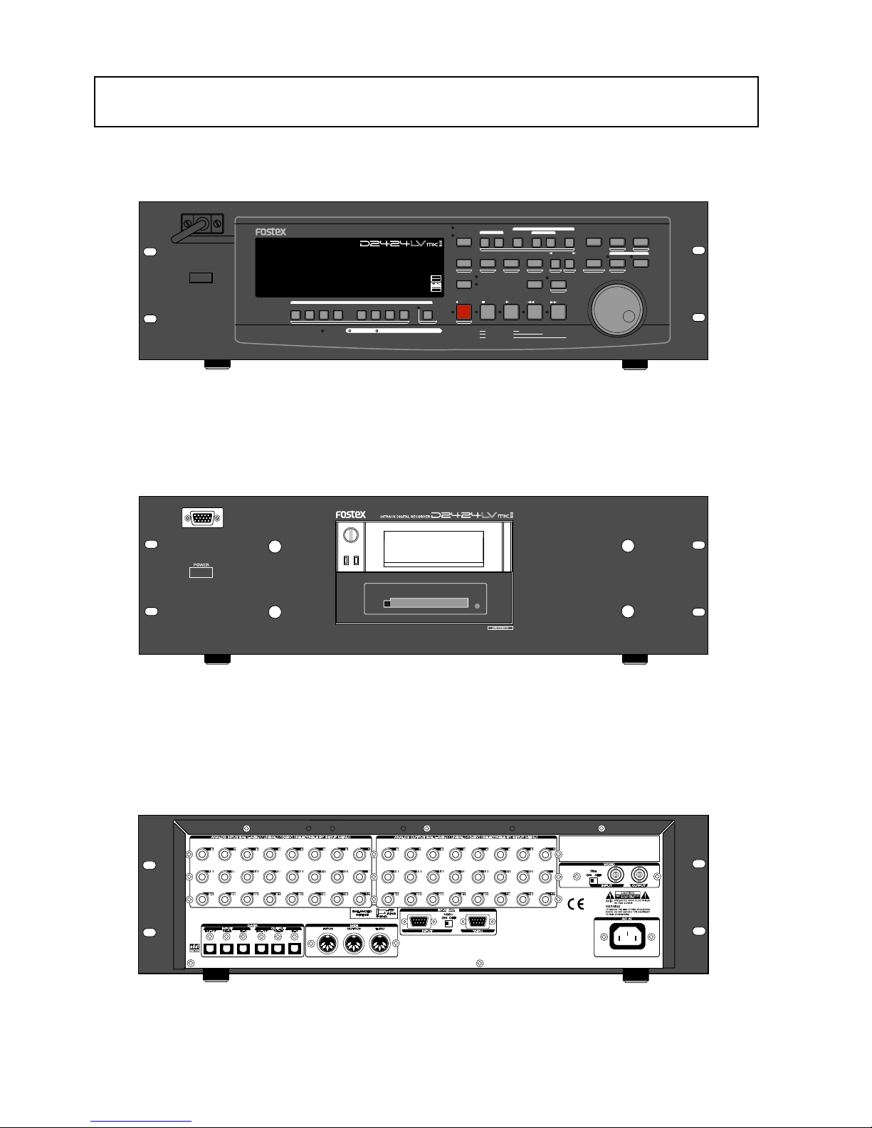
Names and Functions
POWER
HOLD
RECORD
STOP
PLAY
REW
F FWD
ALL INPUT
ALL READY
LOCATE REC END
VARI PITCH
PUNCH
LOCATE
REHEARSAL
TAKE
RECALL
STORE
EXIT/NO
EXECUTE/YES
PGM SEL
NEXT
PREV
UNDO/REDO
PREVIEW
EDIT SETUP
AUTO RTN
OUTIN
AUTO PLAY
START
OUTIN
END
17-24
ACCESS
9-16
1/9/17
2/10/18
3/11/19
4/12/20 5/13/21 6/14/22 7/15/23
8/16/24
FOOT SW
LOCATE ABS 0
CLIPBOARD PLAY
AUTO
TRACK SHIFT
SHIFT
DISP SEL
CHARACTER
TIME BASE SEL
P.EDIT
EJECT
ENVELOPE
CHASE
TC READY TC GEN M.UNDO
TRACK SHIFT
PREV TC
NEXT TC
RECORD TRACK
CLIPBOARD
AUTO PUNCH
AUTO RTN
LOCATE MEMORY
24bit
96kHz
OPTICAL
24TRACK DIGITAL RECORDER
Page 11
Model D2424LVmkII Reference Manual (Names and Functions)
11
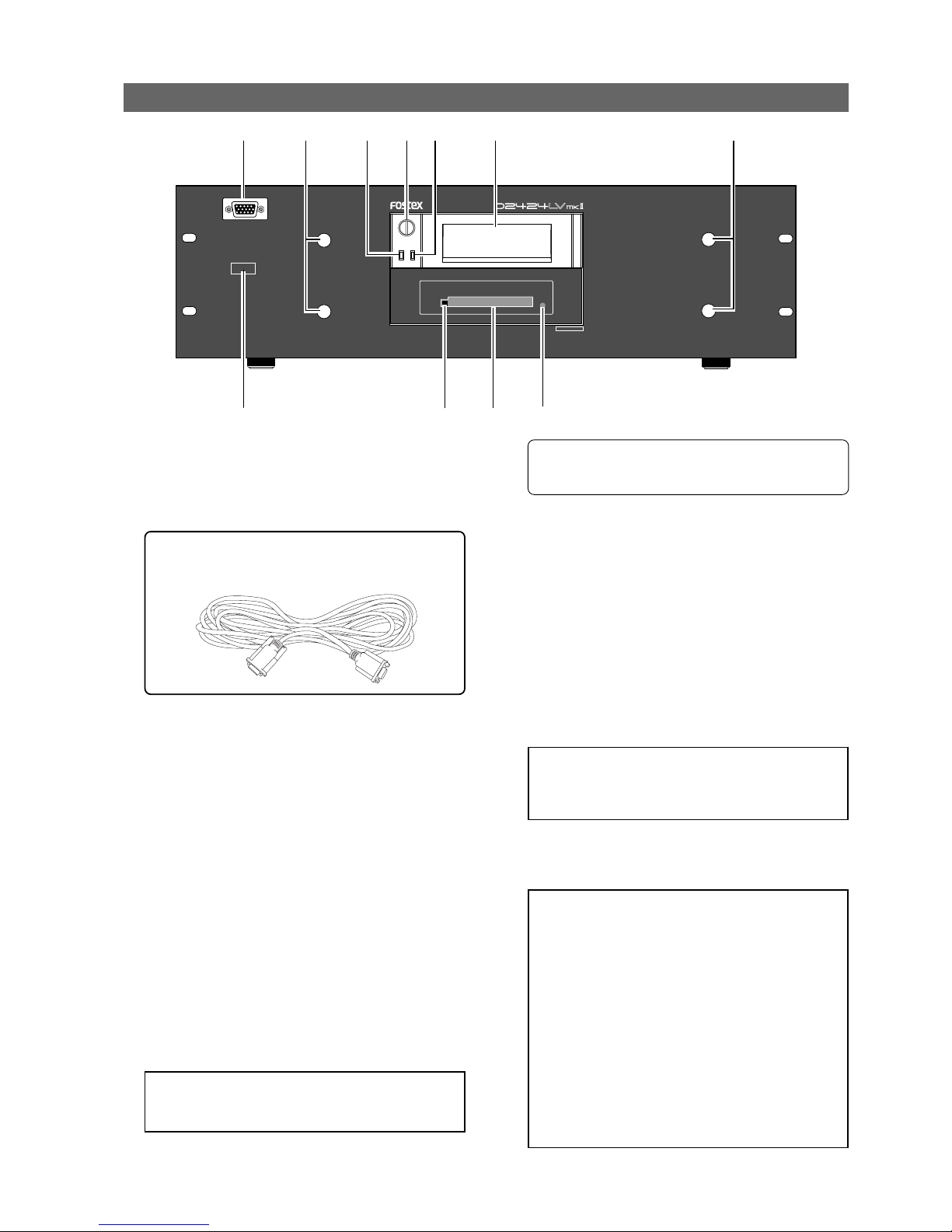
Front Panel section
1. Detachable remote controller connector
The detachable remote controller is connected here.
You can remove the controller.
Connect the optional extension cable (Model 8551B)
to extend the distance.
<WARNING !>:
Before turning the power off to the
recorder, first quit the SETUP mode and make sure
that the recorder section is stopped. Especially, never
attempt to turn off the power to the recorder while
the hard disk is accessing data (the ACCESS LED is
lit or flashing). Otherwise, not only will you lose
recorded data, you may damage to the unit.
<Note>:
Should this power switch be switched On/
Off in quick succession, in some cases it will fail to
switch On at all. This is due to functioning of the
internal protection circuit and is not a breakdown.
Consequently, should such a symptom appear,
switch Off power for a moment, then switch On again
after waiting 1 or 2 minutes.
2. Controller mount
The detachable remote controller is mounted on
the front panel.
3. Hard disk access LED (Red)
This LED lights up or blinks when the hard disk is
writing or reading data. (Same as the ACCESS LED
on the detachable remote controller.)
4. Lock/Unlock key
When you remove or install the hard disk cartridge,
you need to lock/unlock here using the included
key.
5. Hard disk power LED (Green)
This LED lights up if the hard disk operates correctly
when you turn the power on to the recorder.
6. Removable hard disk cartridge slot
This slot is used to insert a removable hard disk
cartridge. This system allows you to replace the
hard disk easily.
<Note>:
The recorder package contains a caddy
(without a hard disk). Install your hard disk in this
caddy.
* Refer to “
Quick operation Guide
” for more
information on how to replace the removable hard
disk cartridge.
7. CF drive indicator
Lights up when a CompactFlashTM card is correctly
set to the CF drive.
8. CF drive for backup
You can set a CompactFlashTM card for data backup
by the FDMS-3 or WAV file format. By installing the
Model 9044 instead of the CF drive, you can use an
E-IDE hard disk for backup. The replacement of the
CF drive with the hard disk drive should be
performed by an authorized person, so ask your
local Fostex dealer or service station.
9. Eject button
Pressing this button ejects a CompactFlashTMcard.
Consult the dealer you purchased the recorder from
or out sales office about information on the
extension cable.
POWER
24bit/96kHz
24TRACK DIGITAL RECORDER
1
2
23
4
5
6
7
10
8
9
10. Power switch
This switch turns the main power to the recorder on/
off.
<Note>:
Before you insert or remove a CompactFlash
TM
card, make sure that the unit is off. If you insert or
remove a card while the unit is on, not only data may
be lost, but also the card or drive may be damaged.
Page 12

Model D2424LVmkII Reference Manual (Names and Functions)
12
1. Controller Connection Cable
Connect this cable to the recorder controller
connection jack.
2. Record track select key
[RECORD TRACK/ENVELOPE]
"SAFE-READY" of the recording track can be selected
(The track can be selected by shifting to 1-8, 9-16
or 17-24 with the [TRACK SHIFT] key.
If the select key is pressed once, that track will be in
the READY state and the track display ( ) will blink.
It will change to SAFE if pressed again and the track
display will be extinguished.
When recording is started from the READY mode,
the blinking track display will light.
If the [RECORD] button only is pressed from the
READY mode, the READY track only will enter input
monitor mode, and the recording level can be
adjusted. If the [RECORD] button is pressed once
again, the D2424LVmkII will return to repro
monitoring.
If any select key is pressed together with the [SHIFT]
key, the envelope function of that track can be
executed. This key is also used for editing such as
copy paste, move paste and erase.
* Refer to page “29” for details about the
reproduction monitor and the input monitor.
* Refer to page “65” for details about the envelope
function.
* Refer to page “71” for details about the copy/paste
and move/paste function.
3. Track shift key [TRACK SHIFT/ALL INPUT]
When selecting a recording track, this is pressed to
shift to the selectable track. With each pressing of
the key, the TRACK SHIFT LED will sequentially
switch in order of:
"Extinguish" - "Lighting of 9-16" - "Lighting of 1724" - "Extinguish" to indicate the modes listed below.
Auto Return/ Auto Play mode is OFF.
(No indication)
AUTO RTN
AUTO PLY
AUTO RTN
AUTO PLY
AUTO RTN
AUTO PLY
AUTO RTN
AUTO PLY
Auto Play mode:
In this mode, playback will start automatically after
the START point is located. This function is effective
at any locate points other than the REC END point.
Auto Return mode:
When the END point is reached during playback, the
START point is automatically located in this mode. This
function is effective only when the START and END
points have been specified.
Detachable Controller section
<Note>:
The Auto Return function is works only
during playback. In the recording mode, the START
point will not be located automatically when the END
point is reached.
4. Auto Play/Auto Return key [AUTO RTN/PLAY]
Pressing this key repeatedly will change Auto Play
mode, Auto Return mode, and Repeat mode On/Off
as follows: (
: LED off, : LED light up)
Auto Play mode is ON.
(Only the AUTO PLAY LED is lit. )
Auto Return mode is ON.
(Only the AUTO RTN LED is lit. )
Auto Repeat mode is ON.
(Both AUTO PLAY and AUT RTN LEDs are lit. )
* All TRACK SHIFT LED extinguished: Tracks 1-8 can be
selected.
* "9-16" are lighted: Tracks 9-16 can be selected.
* "17-24" are lighted: Tracks 17-24 can be selected.
All real track input monitors can be switch on or off
each press of this key while pressing [SHIFT] key.
When all tracks are set to input monitor, the ALL
INPUT LED will light.
HOLD
RECORD
STOP
PLAY
REW
F FWD
ALL INPUT
ALL READY
LOCATE REC END
VARI PITCH
PUNCH
LOCATE
REHEARSAL
TAKE
RECALL
STORE
EXIT/NO
EXECUTE/YES
PGM SEL
NEXT
PREV
UNDO/REDO
PREVIEW
EDIT SETUP
AUTO RTN
OUTIN
AUTO PLAY
START
OUTIN
END
17-24
ACCESS
9-16
1/9/17
2/10/18
3/11/19
4/12/20 5/13/21 6/14/22 7/15/23
8/16/24
FOOT SW
LOCATE ABS 0
CLIPBOARD PLAY
AUTO
TRACK SHIFT
SHIFT
DISP SEL
CHARACTER
TIME BASE SEL
P.EDIT
EJECT
ENVELOPE
CHASE
TC READY TC GEN M.UNDO
TRACK SHIFT
PREV TC
NEXT TC
RECORD TRACK
CLIPBOARD
AUTO PUNCH
AUTO RTN
LOCATE MEMORY
24bit
96kHz
OPTICAL
24TRACK DIGITAL RECORDER
1
23456789
10
11
121314 15
16
17
18
19
20
21
22
23
24
25
26
27
28
29
30
31
34
3233
35
36
Page 13

Model D2424LVmkII Reference Manual (Names and Functions)
13
• Pressing a Memory key to recall the point the key
is storing displays the memory data (time, or bar/
beat/clock) currently stored in that key; then the
recorder enters data edit mode. To edit data, use
the Shuttle dial to move among the digits, and
then use the Jog dial to change the value.
• After you finish editing data, press the
[STORE]
key, and then press one of the Memory keys into
which you want to store the point. The edited
data will be stored in the specified Memory key.
• While the current position of the recorder is
indicated, press the
[STORE]
key, then one of the
Memory keys into which you want to store the
data. The current position or the recorder will be
stored in the Memory key. You can do this while
the recorder is running or stopped.
• Press a desired Memory key, and then press the
[LOCATE]
key to locate the point stored in that
Memory key (time, or bar/beat/clock).
• In Setup mode, you can save or load song data for
each Program.
• All data will be retained after you turn off the
power.
* Refer to page “
54
” for more information on
memory data.
* Refer to page “
58
” for more information on the
Locate function.
* Refer to pages “
27
” and “40” for more information
on the Program Change function.
* Refer to page “
90
” for more information on saving
and loading song data.
5. Clipboard In key [CLIPBOARD IN/PREVIEW]
This key is used to store and recall the In point
(CLIPBOARD IN point) for the Copy or Move
operation. You can locate a stored CLIPBOARD IN
point. If you press the [CLIPBOARD IN] key while
holding down the [SHIFT] key when the recorder is
stopped, you can preview the fade-in part at the
stored CLIPBOARD IN point.
* Refer to page “71” for copying/moving data.
* Refer to page “
58
” for locating the CLIPBOARD IN
point.
* Refer to page “
67
” for previewing data at the
CLIPBOARD IN point.
6. Clipboard Out key [CLIPBOARD OUT/PREVIEW]
This key is used to store and recall the Out point
(CLIPBOARD OUT point) for the Copy or Move
operation. You can locate a stored CLIPBOARD OUT
point. If you press the [CLIPBOARD OUT] key while
holding down the [SHIFT] key when the recorder is
stopped, you can preview the fade-out part at the
stored CLIPBOARD OUT point.
* Refer to page “58” for locating the CLIPBOARD OUT
point.
* Refer to page “
71
” for copying/moving data.
* Refer to page “
67
” for previewing data at the
CLIPBOARD OUT point.
7. Auto Return Start key
[AUTO RTN START/PREVIEW]
This key is used to store and recall the start point
(AUTO RTN START point) for the Auto Return or
Auto Repeat operation. You can locate a stored
AUTO RTN START point. If you press the [AUTO
RTN START] key while holding down the [SHIFT] key
when the recorder is stopped, you can preview the
fade-in part at the stored AUTO RTN START point.
* Refer to page “58” for locating the AUTO RTN
START point.
* Refer to page “
71
” for copying/moving data.
* Refer to page “
67
” for previewing data at the AUTO
RTN START point.
8. Auto Punch In key [AUTO PUNCH IN/PREVIEW]
This key is used to store and recall the recording
start point (AUTO PUNCH IN point) for the Auto
Punch IN/OUT operation. This point is also used as
an erase point. You can locate a stored AUTO PUNCH
IN point. If you press the [AUTO PUNCH IN] key while
holding down the [SHIFT] key when the recorder is
stopped, you can preview the fade-out part at the
stored AUTO PUNCH IN point.
* Refer to page “43” for more information about
Auto Punch In/Out recording.
* Refer to page “
71
” for more information about
pasting data.
* Refer to page “
75
” for more information about the
Erase operations.
* Refer to page “
67
” for previewing data at the AUTO
PUNCH IN point.
9. Auto Punch Out key [AUTO PUNCH OUT/PREVIEW]
This key is used to store and recall the recording
end point (AUTO PUNCH OUT point) for the Auto
Punch IN/OUT operation. This point is also used as
an erase point. You can locate a stored AUTO PUNCH
OUT point. If you press the [AUTO PUNCH OUT] key
while holding down the [SHIFT] key when the
recorder is stopped, you can preview the fade-in
part at the stored AUTO PUNCH OUT point.
* Refer to page “43” for more information about Auto
Punch In/Out recording.
* Refer to page “
75
” for more information about the
Erase operation.
* Refer to page “
67
” for previewing data at the AUTO
PUNCH OUT point.
Memory keys (CLIPBOARD IN, CLIPBOARD OUT,
AUTO RTN START, AUTO PUNCH IN, AUTO PUNCH
OUT, and AUTO RTN END keys) have the following
common functions:
Auto Repeat mode:
This mode is a combination of Auto Play and Auto
Return, and plays back the part between the START
and END points repeatedly. The auto repeat function
is effective only when the START and END points have
been specified correctly.
* Refer to page “60” for details.
Page 14
Model D2424LVmkII Reference Manual (Names and Functions)
14
15. Execute/Yes key [EXECUTE/YES/CHASE]
Press this key to execute the operation when you
edit data on the hard disk using the edit functions
such as Paste and Erase, when you put the recorder
into SETUP mode, or when you set the parameters
in the SETUP menu.
Pressing this key while holding down the [SHIFT]
key allows you to select the Slave mode on/off.
* Refer to page “71” for more information about
using this key for the Paste or Erase operation.
* Refer to page “
108
” for more information about
using this key in SETUP mode.
* Refer to page "
85
", “88” for more information about
using this key for the Slave Mode operation.
14. Exit/No key [EXIT/NO/EJECT]
The opposite of the [EXECUTE/YES] key, this key is
used to stop operation.
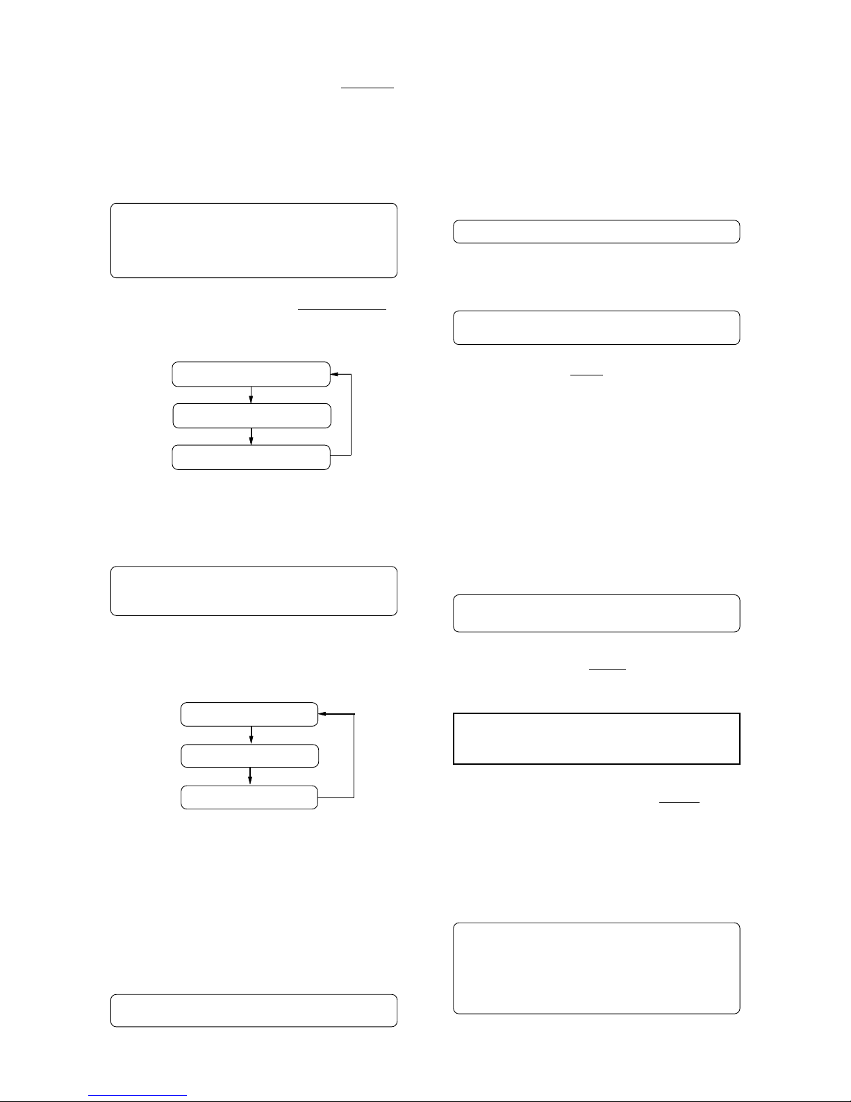
11. Display Select key [DISP SEL/TIME BASE SEL]
This key is used to change the display mode.
Pressing this key repeatedly will change the display
mode as follows:
* Refer to page "26" in regards to REMAIN, page "
108
"
on the SETUP menu, and the "
APPENDIX
" on details
if the Model 8346 TC/SYNC card is installed.
Pressing this key while holding down the [SHIFT]
key will switch the Time Base (*) as follows.
The Time Base can be set when the display shows
the recorder’s current position or the available disk
space (REMAIN).
* Refer to pages “25” and “
108
” for more information
about MTC and the internal Tempo Map.
(*) Time Base:
The recorder uses time display (ABS or MTC) or Bar/
Beat/Clock display to indicate the current position of
the recorder section. These displays are called “Time
Base.” ABS (Absolute Time) shows the absolute time of
the disk, and MTC (MIDI Time code) shows the relative
time obtained by adding an MTC offset value to the
ABS value.
Bar/Beat/Clock (BAR/BEAT/CLK) indicates a position
within a piece of music and conforms to the MIDI clock
and Song Position Pointers created on the internal
Tempo Map.
10. Auto Return End key [AUTO RTN END/PREVIEW]
This key is used to store and recall the end point
(AUTO RTN END point) for the Auto Return or Auto
Repeat operation. You can locate a stored AUTO
RTN END point. If you press the [AUTO RTN END]
key while holding down the [SHIFT] key when the
recorder is stopped, you can preview the fade-out
part at the stored AUTO RTN END point.
* Refer to page “58” for locating the AUTO RTN END
point.
* Refer to page “
71
” for copying/moving data.
* Refer to page “
67
” for previewing data at the AUTO
RTN END point.
12. Program select key [PGM SEL]
This key has the following two functions depending
on the setup condition of "Chain Play?" (Setup of
the Chain Play Mode) in the SETUP mode.
* Refer to page “40” for program select function.
13. Store key [STORE/HOLD]
This key is for storing time figures (or measure/
beat/clock figure) in any memory key.
Following this key, when each memory key is
pressed, data shown in the display will be stored in
their respective memory key.
Using "Press LOCATE: **", which is shown after
pressing the [RECALL] key, if this key is pressed after
input of any number (00-99) in "**," it is registered
as time data for the specified locate number.
If this key is pressed while holding down on the
[SHIFT] key, the currently shown time (BAR/BEAT/
CLK) will be held and this data can then be edited.
After editing, the time thus edited will be stored
using the procedure above.
* Refer to page “54” for registering in the memory
key.
If an optional Model 8346 TC/SYNC card is installed,
information in the MTC IN or TC IN will differ
depending on "Ref. TC?" menu setting (MTC or LTC)
in the SETUP mode. If the card is not installed, "00H
00M 00S 00F 00SF" will always be displayed.
The current position
Disk space (remain)
MTC IN or TC IN display
ABS time base
Bar/beat/clk time base
MTC time base
<When the "Chain Play?"menu is set to other than "Off">
You can specify the program at executing chain play
when this key is pressed.
* Refer to page “61” for details on the chain play
mode.
<When the "Chain Play?" menu is set to "Off">
The D2424LVmkII will switch to setup of a new
program and the program select execution mode
when this key is pressed.
<Note>:
The "EJECT" function (the SHIFT function
of the key) is reserved for future function and is not
supported by this version.
Page 15

Model D2424LVmkII Reference Manual (Names and Functions)
15
19. Jog/Shuttle dial
Jog dial (inside):
Turning the Jog dial while the recorder is stopped
performs digital scrubbing in either direction, which
allows you to check the audio and locate a point without
any change in pitch.
The Jog dial is also used to change values in the data
edit mode or when the pitch data is displayed. It also
allows you to select a parameter to set in Setup mode.
Shuttle dial (outside):
FWD and REW direction shuttle operation in the STOP
mode is possible at +/-1 ~ 64 times fast winding in the
no sound state. On the other hand, FWD and REW
direction shuttle operation in the PLAY mode is possible
in the CUE playback mode at +1 ~ 8 and -1 ~ -7 times
speed while cueing. In addition, while in the display
edit mode, the editing point can be moved.
* Refer to page “54” for more information about the
editing the memory data.
* Refer to page “
108
” for more information about
SETUP mode.
* Refer to page “
65
” for more information about
Digital Scrubbing.
16. Recall key [RECALL]
This is pressed to call out the time figure (or bar/
beat/clk figure) data stored in locate number (0-
99). If the [LOCATE] key is pressed after pressing
this key, the RECALL LED will light and "Press
LOCATE: **" is displayed. Next, by pressing the
[LOCATE] key after specifying a desired locate
number, the time figure in memory will be recalled
into the specified number and the recorder will enter
the edit mode. Press the [LOCATE] key to execute
this time figure.
* Refer to page "58" for more information about using
this key for the Locate operation.
17. Next key [NEXT/NEXT TC]
If this key is pressed when in the recorder is in the
PLAY/STOP/F FWD or REW mode, locate will be
executed to the next memory point from the present
location point.
When inputting characters in the title edit mode, it
serves as a character short cut function.
The memory number can be advanced with each
press of this key when the recorder displays "Press
LOCATE: **".
With an optional Model 8346 TC/SYNC card
installed, if this key is pressed while pressing down
the [SHIFT] key, the recorder will locate from the
head of the currently recorded time code to the head
of the next time code event.
18. Previous key [PREV/PREV TC]
If this key is pressed when the recorder is in the
PLAY/STOP/F FWD or REW mode, locate will be
executed to the one previous memory point.
When inputting character in the title edit mode, this
serves as a character short cut function.
The memory number selecting during display of
"Press LOCATE: **", the memory number can be
reverted with each press of this key.
With an optional Model 8346 TC/SYNC card
installed, if this key is pressed while pressing down
the [SHIFT] key, the recorder will locate from the
currently recorded time code to the head of the
previous time code event.
20. Vari-pitch key [VARI PITCH/P. EDIT]
Use this key to turn the Vari-pitch function on and
off. When this function is enabled, the
corresponding LED lights up. When this function is
disabled, the LED turns off. The range of pitch
variation for playback and recording is +/-6.0%, in
0.1% steps.
Press the [SHIFT] key, and then the [VARI PITCH] key
to display the current pitch data.
To change the pitch data, use the Jog dial to change
the value while the pitch data is displayed.
You can also change the playback speed when the
data is being played back with the Vari-pitch
function ON. To quit the pitch data display, press
the [EXIT/NO] key, or the [STOP] button.
<Notes>
* Even if the pitch data is 0.0% (no speed change),
pressing the
[VARI PITCH]
key will still turn on the
VARI PITCH function. The speed is not changed,
but the Vari Pitch is turned on.
* The Vari Pitch function will automatically turn off
under the following conditions:
1. You have turned off and on the power to this recorder.
The pitch data will be reset to 0.0%.
2. You have pressed the [EXECUTE/YES] key while
holding down the [SHIFT] key to turn the "SLAVE
mode" on (the setting pitch data remains).
3. You set "Digital In" of the SETUP mode to a SYNC
mode ("SPDIF :Sync" or "adat :Sync") and the
recorder is locking to the external clock from DIGITAL
IN or WORD IN. In consequence, "DIGITAL" and
"EXT" indicators light in the display.
4. You have installed the optional Model 8346 TC/SYNC
card in this recorder and set the LTC OUT to "Gen.".
* Refer to “
Quick Operation Guide
” for more
information on the Vari-pitch function.
* Refer to pages “
85
” and “88” for more information
on Slave mode.
21. Fast Forward button [F FWD]
Pressing this button while the recorder section is
stopped will fast forward data at 30 times speed.
Pressing this button in Play mode will cue data (you
can hear sound during the fast forward operation)
at five times speed.
Pressing this button while holding down the [STOP]
button will initiate the “LOCATE ABS REC END”
operation, and immediately locate the end of the
recorded data on the Program (ABS REC END). (Refer
to the “[STOP] button” section for more information
about LOCATE ABS REC END.)
Page 16
Model D2424LVmkII Reference Manual (Names and Functions)
16
27. Stop button [STOP]
Pressing this button will stop the transport section
of the recorder. Pressing the PLAY, REWIND, or F
FWD button while holding down this button will
cause the recorder to perform the following
operation:
[STOP] button + [PLAY] button
Pressing the [STOP] button will abort the editing
operations and display the current position of the
recorder, if you wish to:
* quit the data edit mode,
* cancel the recall or store operation,
* quit the pitch data display,
* cancel the edit operation, such as pasting, or
* cancel the SETUP menu settings.
Pressing the foot switch while holding down this
button allows you to turn the punch in/out rehearsal
mode ON/OFF.
*1 Clipboard playback:
The recorder plays back the copy data or move data
for the Clipboard. During audio playback of the copy
or move data, the FL will display the time length and
data type (“Copy Clip Play!” or “Move Clip Play!”), and
the copy or move source track indicator will flash,
enabling you to quickly determine the track and data
type.
24. Undo/Redo key [UNDO/REDO/M. UNDO]
If you wish to restore the status prior to editing,
recording, or performing a punch in/out take, press
the [UNDO/REDO] key. Pressing the [UNDO/REDO] key
again will return you to where you were before you
pressed the [UNDO/REDO] key the first time.
If the current drive you are using has been formatted
with the multiple undo function switched ON, you
can execute multiple undo by pressing this key while
holding down the [SHIFT] key.
22. Locate key [LOCATE]
Use this key to start to start the LOCATE feature.
Pressing this key after a memory key (CLIPBOARD
IN/OUT, AUTO RTN START/END, AUTO PUNCH IN/
OUT) locates the memory data programmed in each
respective key (time mode or bar, beat, clock
setting).
The data can be programmed by individually setting
it with one of the 99 (01-99) LOCATE numbers of
the [LOCATE] key.
Note that the data of memory number 00 is available
in addition to LOCATE numbers 01-99.
The last LOCATE time setting (bar, beat, clock
setting) constantly replaces the data stored in the
[LOCATE] key as data in memory number 00.
Therefore, it is possible to press this key alone to
repeatedly LOCATE the same point.
These data can be individually stored in programs
P1-P99. The data for each program is SAVED or
LOADED for each program when the song data is
designated for SAVE/LOAD in the SETUP mode.
This data is maintained even when the power is
turned OFF.
* Refer to page “58” for more information about the
Locate function.
25. Play button [PLAY]
Pressing this button will cause the recorder to play
back. Pressing this button while holding down the
[RECORD] button will start recording.
Pressing this button while holding down the [STOP]
button will perform the Clipboard playback
operation. Refer to the section “[STOP] button” for
more information on the Clipboard playback.
Pressing the [PLAY] button during recording will stop
recording.
23. Rewind button [REWIND]
Pressing this button while the recorder section is
stopped will rewind data at 30 times speed.
Pressing this button in Play mode will cue data (you
can hear sound while rewinding) at five times speed.
Pressing this button while holding down the [STOP]
button will perform the “LOCATE ABS 0” operation,
and immediately locate the beginning of the
Program (ABS TIME: 00M: 00S: 00F). (Refer to the
“[STOP] button” section for more information about
LOCATE ABS 0.)
26. Setup key [SETUP/TC GEN]
Press this key to puts the recorder in the SETUP
mode to execute various operations. This key works
when the recorder is stopped. To exit from the
SETUP mode, either press the [EXIT/NO] key or the
[STOP] button. If the optional Model 8346 TC/SYNC
card is installed and external time code is being
input, you can enter the generator setup mode by
pressing this key while pressing on the [SHIFT] key.
* Refer to page “
108
” for more information on SETUP
mode.
* Refer to "
APPENDIX
" for more information about
generator setup mode.
<Note>:
This key is enabled only when the recorder
is stopped.
* Refer to pages “
45
”, “47”, “73” and “76” for more
information about the single Undo/Redo
operation.
* Refer to page "
69
" for more information about
Multiple Undo function.
[STOP] button + [REWIND] button
[STOP] button + [F FWD] button
Clipboard playback (The STOP LED will flash and
the PLAY LED will light up.) *1
Locate ABS 0 *2
Locate REC END *3
Page 17
Model D2424LVmkII Reference Manual (Names and Functions)
17
29. Record button [RECORD]
Pressing only this button places the readied tracks
into input monitoring status. Pressing this button
again will reset the tracks to playback monitoring.
(The RECORD LED will blink when the readied tracks
are in input monitoring status.)
Pressing the [PLAY] button while holding down this
button will place the readied tracks into recording.
At this time, the PLAY LED and RECORD LED will
light, and the readied track indication will be light
steadily (instead of blinking).
* Refer to page “29” of the “Before Starting” section
for more information about input monitoring and
reproduce monitoring.
* Refer to page “
25
” of the “Before Starting” section
for more information about ABS 0 and ABS END.
* Refer to page “
46
” for more information about
Punch In/Out recording using the foot switch.
* Refer to page "
73
" on details for "Clip board play."
* Refer to page "
58
" on details for "LOCATE 0" and
"LOCATE REC END."
28. Edit key [EDIT/TC READY]
Pressing this key enters the recorder to the menu
select mode for editing tracks. Press this key
repeatedly or turn the Jog dial to select menu.
Edit menus appear in the following order.
To execute a desired menu, select the menu, then
press the [EXECUTE/YES] key. To exit the selection
mode, press the [EXIT/NO] key.
If the optional Model 8346 TC/SYNC card is installed,
you can enter the TC READY mode for recording
time code by pressing this key while pressing on
the [SHIFT] key.
* Refer to page “71” for more information about
“Copy Clip,” “Move Clip,” “Copy Paste,” “Erase,”
and “Track Exchange.”
* Refer to page “
39
” for more information about
program duplicate function.
<Note>:
This key is enabled only when the recorder
is stopped.
30. Auto Punch Mode On/Off key [AUTO PUNCH]
Switch this key ON for auto punch in/out.
When you press this key while a correct value is
stored to the [AUTO PUNCH IN] key and the [AUTO
PUNCH OUT] key, both the REHEARSAL LED and TAKE
LED will blink, indicating that Auto Punch mode is
on. (If a correct value is not stored, pressing the
[AUTO PUNCH] key will not turn the parameter ON,
and the message “Void Out Point!” will appear.)
Pressing the [PLAY] button under this condition will
put the recorder into “Rehearsal mode” for Auto
Punch In/Out recording. Pressing the [PLAY] button
and [RECORD] button simultaneously will put the
recorder into “Take mode.”
There are five combinations of the REHEARSAL LED
and TAKE LED that indicate the status of the recorder
regarding auto punch recording:
*2 Locate ABS 0:
The recorder will locate the top of the selected Program
(ABS TIME: 00M: 00S: 00F).
*3 Locate REC END:
The recorder will locate the end of the recorded data
on the Program (ABS REC END).
These operations can be executed only on real
tracks.
Auto Punch mode OFF
Both REHEARSAL LED and TALE LED are off.
Auto Punch mode ON
Both REHEARSAL LED and TALE LED are blinking.
Auto Punch TAKE mode
Only the TAKE LED (red) is lit.
Auto Punch REHEARSAL mode
Only the REHEARSAL LED (green) is lit.
Rehearsal mode entered by means of MMC or foot switch
Only the REHEARSAL LED (green) is blinking.
Copy Clip?
Move Clip?
Copy Paste? (Move Paste?(*1))
Erase?
Track Exchange?
PGM Duplicate?(*2)
(*1): After you execute copy clip, “Copy Paste”
appears. After you execute move clip, “Move Paste”
appears.
(*2): The program duplicate display will appear
only if the current drive was set to ON for the
"Multiple Undo Function" when formatting.
If the current drive is set to OFF, the program
duplicate display will not appear even if the [EDIT]
key is pressed.
Page 18
Model D2424LVmkII Reference Manual (Names and Functions)
18
32. All Input LED [ALL INPUT]
This is lit when all track input monitors are set to
ON by pressing the [TRACK SHIFT] key while pressing
the [SHIFT] key, and extinguished when set to OFF.
While in the SETUP mode, it is also possible to
automatically set it to all input monitors while the
recorder is in the stop mode.
35. Foot switch jack [FOOT SW]
(Connector: PHONE jack)
Punch in/out (also for rehearsal) or PLAY/STOP of
the recorder can be done by foot by connecting the
optional foot switch.
The foot switch function can be changed in the
SETUP mode. It will not function for punch in/out
function in the initial setting.).
33. Track shift LED [9-16, 17-24] (green)
This is lit when the selectable recording track is
shifted to 9-16 or 17-24.
<Note>:
Be sure to use an “
unlatch type
” foot switch
if you use a foot switch. Otherwise, a malfunction
could occur.
* Refer to page “
46
” for information about Punch
In/Out recording using the foot switch.
31. Shift key [SHIFT]
Press a key, or button while holding down the [SHIFT]
key to activate the following “shift-invoked”
functions.
[VARI PITCH] key
[RECORD TRACK]
select keys
[TRACK SHIFT] key
[RECORD] button
[CLIPBOARD IN/OUT] key
[AUTO PUNCH IN/OUT] key
[AUTO RTN START/END] key
[EXIT/NO] key
[EXECUTE/YES] key
[DISP SEL] key
[EDIT] key
[SETUP] key
[UNDO/REDO] key
Executes the envelope function of the
selected track.
Switches ON/OFF of the input monitor for
all tracks.
Switches SAFE-READY for all tracks.
Executes preview of the stored point of
each memory key.
Reserved for future function. Not
supported by this version.
Switches the slave mode ON/OFF.
Selects the time base.
Switches TC READY ON/OFF.
Enters the TC GEN setup mode.
Enters the multiple undo executing mode.
* Refer to page “
108
” for details on the SETUP mode.
* Refer to the
"APPENDIX"
at end of this manual in
regards to the TC generator mode.
* Refer to page "
69
" for details on multiple undo
function.
* Refer to the
"Quick Operation Guide"
in regards to
editing of Vari Pitch data.
* Refer to page "
67
" for details on preview.
* Refer to page "
65
" for details on the envelope
function.
Enters the vari pitch data editing mode.
36. Meter display
This meter display shows the signal level and
settings.
* Refer to the “Display section” on page “19.”
* For details, refer to page
29
at end of this manual.
Key with SHIFT function
Function
* Refer to page “43” for details about Punch In/
Out operation.
<Note>:
If a correct value is not stored, pressing
the
[AUTO PUNCH]
key will not enable the function,
and the message “
Void Out Point!”
will appear.
If a correct value is not stored, pressing the
[AUTO
PUNCH]
key will not turn on the function, and the
message “
Void Out Point!
” will alert you. In this case,
set a correct value for the Auto Punch In/Out point.
Also, the function is not turned on when you press
the
[AUTO PUNCH]
key if the disk does not have
enough recording space. The display will indicate
“
-**H **M **S **F Over.
”
34. Hard disk access LED (green)
This LED lights up or blinks when the hard disk is
writing or reading data.
<CAUTION>:
Do not turn the power off while this
LED is lit or blinking. Otherwise, data on the hard
disk may be damaged.
[NEXT] key
The recorder will locate to the head of the
next time code event, subsequent to the
recorded time code. This functions only
when an optional Model 8346 is installed.
The recorder will locate to the head of the
time code event previous to the recorded
time code.
This functions only when an optional Model
8346 is installed.
[PREV] key
[STORE] key
Holds the current time data, which you can
edit.
Page 19
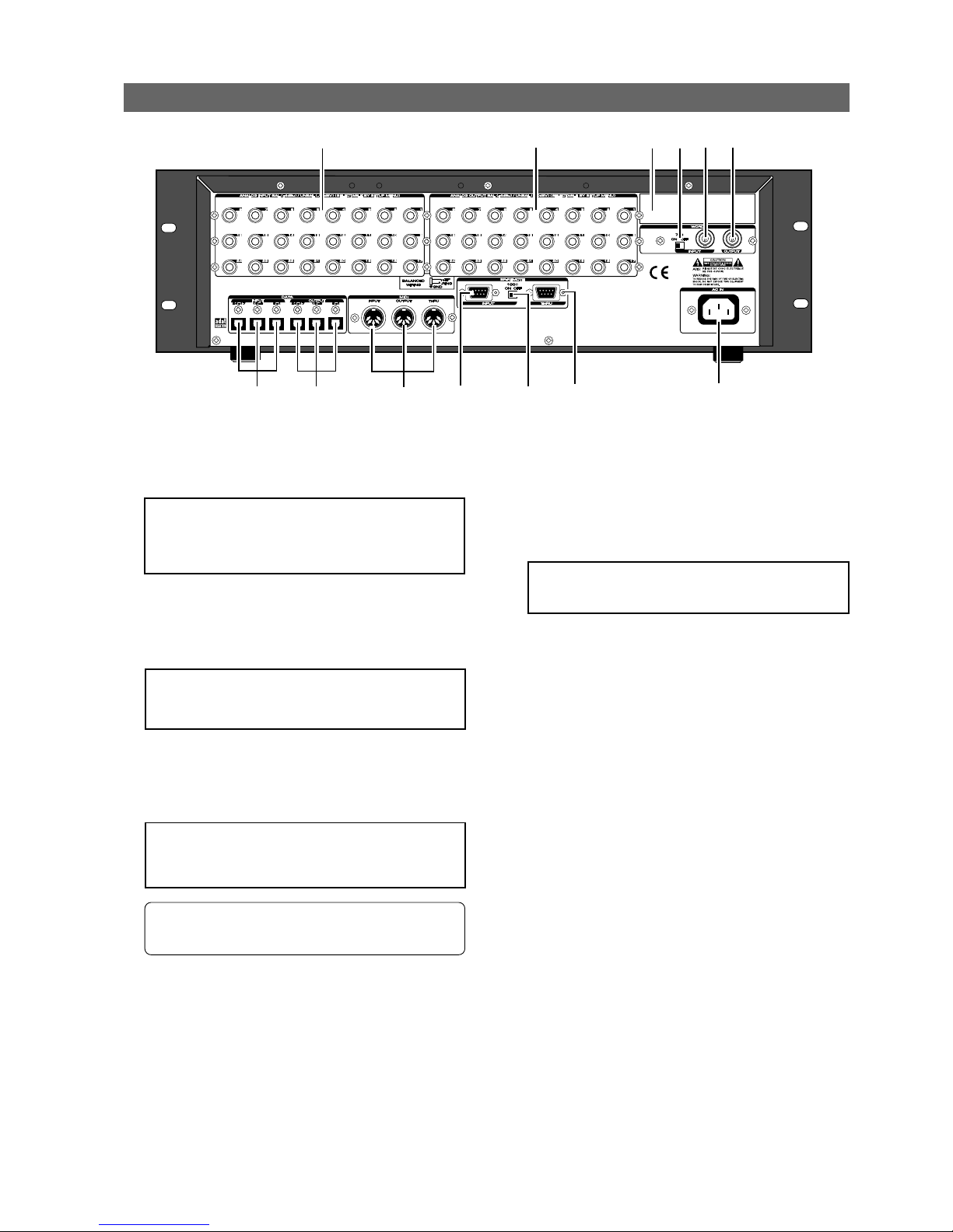
Model D2424LVmkII Reference Manual (Names and Functions)
19
4. WORD IN terminating switch (75Ω)
This is the [WORD IN] port terminating switch (75Ω).
Turn this ON when inputting an external word clock
signal into the [WORD IN] connector from digital
equipment.
5. WORD INPUT connector (Connector: BNC)
Word clock signal from external digital equipment
is input here for the purpose of phasing with
external digital equipment.
6. WORD OUTPUT connector (Connector: BNC)
Word clock signal from the recorder is output to
external digital equipment.
Rear panel section
<Note>:
Installation of the option must be done by
our Fostex Service Station. For details, please inquire
at your nearest Fostex Service Station.
1. Analog Input jacks 1~24 (Connector: PHONE)
External analog audio signals to the D2424LVmkII are
input here. These are connected, for example, to
external mixer's group out (BUSS OUT) connectors.
7. AC IN connector
The power cable packaged with this recorder is
connected here.
8. REMOTE THRU connector
(Connector: D-sub 9-pin)
RS-422 control signal (SONY 9PIN PROTOCOL or
Fostex System Exclusive Message) input from the
[REMOTE INPUT] connector is output here.
This is connected to the second recorder REMOTE
INPUT when controlling a multiple number of
recorders.
9. REMOTE INPUT terminating switch (100Ω)
This REMOTE INPUT terminating switch (100Ω) is
switched ON for normal use of an inputted RS-422
control signal into the [REMOTE INPUT] connector.
When controlling a multiple number of recorders,
the last one only is switched ON; the others are
switched OFF.
<Note>:
Always plug the power cable to the recorder
before plugging the cable into the wall outlet.
<Note>:
Analog input/output can be switched for
balance (+4dBu)/unbalance (-10dBV) via the SETUP
mode. At initial setup, it is set for unbalance (10dBV).
• For functions at installation of the optional Model
8346, please refer to "
APPENDIX"
on the last page
of this manual.
2. Analog Output jacks 1~24 (Connector: PHONE)
Analog audio signals (Channels 1-24) from
D2424LVmkII are output here. For example, this is
connected to the external mixer [TAPE IN] connector.
<Note>:
When using a current drive formatted to
96kHz 24 bits or 88.2kHz 24 bits, only [OUTPUT 18] will be functional.
3. Optional Panel
The additional installation panel for the optional
Model 8346 (TC/SYNC card x1). Normally, it can be
used with the panel remained installed.
10. REMOTE INPUT connector
(Connector: D-sub 9-pin)
External RS-422 control signal (SONY 9PIN PROTOCOL
or Fostex System Exclusive Message) is input here to
control this recorder.
3
2
1
12
11
8
7
4
5 6
10
9
13
Page 20
Model D2424LVmkII Reference Manual (Names and Functions)
20
The recorder display integrates the level meter of a high-visibility FL tube with a 16 digits and 35 dot message
display. The level meter shows the Track 1-24 output level of the recorder section. The time display shows
the current time of the recorder section using ABS TIME (Absolute time), MTC (MIDI time code), or MIDI BAR/
BEAT (bar/beat). This display also shows messages required for interactive operation. The following section
explains the display functions and provides with some examples.
Display section
1. Display shown when the power is turned on
When you turn on the power to the recorder and the connected E-IDE hard disk (a formatted hard disk),
the display shows the [Initializing...] message, [Current Dr], the name of the connected current drive, then
recording mode (Standard format, etc.), and finally the top position of the disk in the time base (ABS, MTC,
or BAR/BEAT/CLK) used in the last Program before you turned the power off.
The following example indicates that the recorder started with the ABS Time Base used in Program 1.
<for song data>
[DATA OUTPUT] 1-8 must be used (the other connectors
do not feed song data).
<for S/P DIF digital signals>
[DATA OUTPUT] 1-8 feeds the signal for tracks 1-2.
[DATA OUTPUT] 9-16 feeds the signal for tracks 3-4.
[DATA OUTPUT] 17-24 feeds the signal for tracks 5-6.
<for adat digital signals>
[DATA OUTPUT] 1-8 feeds the signal for tracks 1-8.
[DATA OUTPUT] 9-16 feeds the signal for tracks 9-16.
[DATA OUTPUT] 17-24 feeds the signal for tracks 17-
24.
13. DATA INPUT connectors [1-8, 9-16, 17-24]
(Connector: OPTICAL)
These connectors receive song data (sound data +
various setup data) from an external digital device,
as well as receive S/P DIF or adat digital signals from
external digital equipment (such as DAT recorder,
MD recorder, CD player, adat equipment/digital
mixer, etc.).
Depending on usage, the appropriate connectors
should be used as follow.
* Refer to page “90” for information about “LOAD”
function.
* Refer to page “
48
” for information “Recording
Digital Data.”
11. MIDI Input/Output/Thru connector
(Connector: DIN 5-pin)
MIDI INPUT:
Connect the [MIDI OUTPUT] connector of an external
MIDI device here. The recorder can be controlled
remotely via an external MMC (MIDI Machine Control)
or FEX (Fostex System Exclusive Message).
MIDI OUTPUT:
Connect the [MIDI INPUT] connector of the external MIDI
device here. The recorder will output MTC (MIDI Time
Code), MIDI Clock signal, MMC (MIDI Machine Control)
response, and FEX (Fostex System Exclusive Message)
response.
MIDI THRU:
This connector outputs the input signal at the [MIDI
INPUT] connector without modification. When using
multiple recorders via MIDI, connect this terminal to
the [MIDI INPUT] connector of the second recorder.
12. DATA OUTPUT connectors [1-8, 9-16, 17-24]
(Connector: OPTICAL)
Feed song data of the D2424LVmkII (sound data +
various setup data) for saving data to an external
digital device, as well as feed S/P DIF or adat digital
signals to external digital equipment.
Depending on usage, the appropriate connectors
should be used as follows.
<for song data>
[DATA INPUT] 1-8 must be used (the other connectors
do not receive song data).
<for S/P DIF digital signals>
[DATA INPUT] 1-8 receives S/P DIF signal and routes
to tracks 1-2.
[DATA INPUT] 9-16 and [DATA INPUT] 17-24 do not
receive any signal.
<for adat digital signals>
[DATA INPUT] 1-8 receives adat signals and routes to
tracks 1 through 8.
[DATA INPUT] 9-16 receives adat signals and routes
to tracks 9 through 16.
[DATA INPUT] 17-24 receives adat signals and routes
to tracks 17 through 24.
<Note>:
The [DATA INPUT] and [DATA OUTPUT]
connectors do not support 96kHz FS adat digital
signals.
Page 21
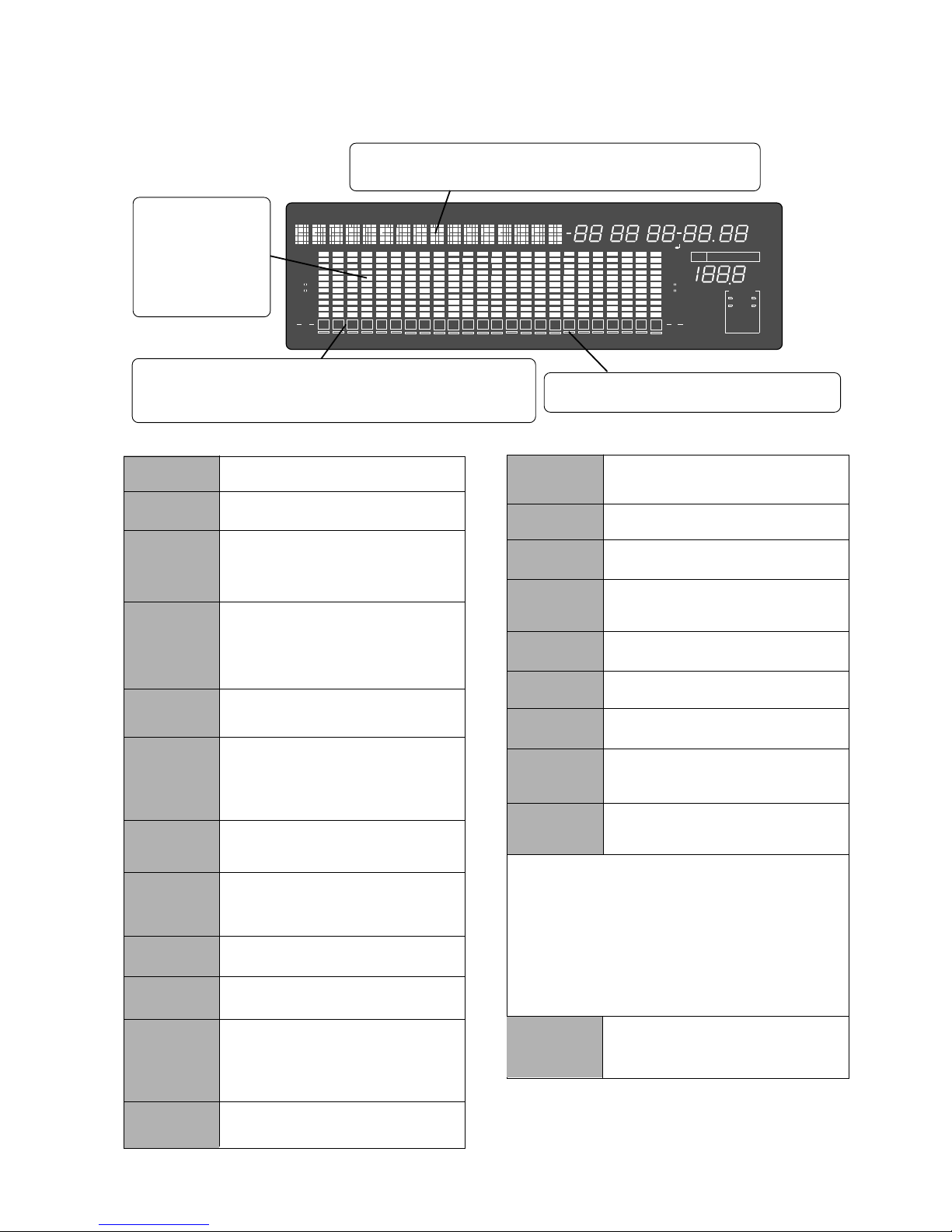
Model D2424LVmkII Reference Manual (Names and Functions)
21
2. Preset Display
The display below shows all preset items for explanation purpose.
Level meter
Displays recorder output
level or recording level
for each track.
In the programs to 96
kHz 24 bits or 88.2 kHz
24 bits, only tracks 1-8
will function.
Track indications
Each frame will blink when the track is READY, be extinguished in the SAFE
mode and be lighted during recording. In the program to 96 kHz / 24 bits
and 88.2kHz 24bits, only tracks 1-8 will function.
ABS
MTC
SIGNATURE
LOCATE
REMAIN
MTC IN
MTC OFFSET
TC IN
CHASE
PGM
Lights up when ABS is selected as Time base.
Lights up when MTC is selected as Time Base.
Lights up to indicate a bar/beat/clock value when
BAR/BEAT/CLK is selected as Time Base.
Lights up to indicate available recording time and
space on the disk.
With the optional Model 8346 TC/SYNC card
installed, this will be lit when MTC or LTC is
externally input.
Lights up when MTC OFFSET menu is selected
in SETUP mode.
Flashes when "Slave mode" is turned on.
When a signal is locked, the flashing indicator lights
up steadily.
Lights up to indicate the current program number.
35 dot message display
This display indicates the ABS time, MTC time value or bar/beat/clock value,
and a parameter name in the SETUP mode.
TEMPO
BIT 16, 24
FS
Hz
Lights up when the tempo setting menu is selected
in SETUP mode.
Sampling frequency/quantization at formatting
are displayed. This will also blink to warn that
digital signals (S/P DIF or adat) of a wrong
sampling frequency are being input.
SURE?
This message is shown to confirm whether or not
you wish to execute a certain operation.
COMPLETED!
Lights up when the recorder enters data edit mode,
enabling you to edit data. Pressing the LOCATE
key while this indicate is lit will cause the recorder
to locate the position of the displayed time or the
bar/beat/clock value.
This message indicates that an operation such
as copy, move and paste has been completed.
%
FSMH
DIGITAL
∞
42
OL
0
30
24
18
12
9
6
3
DIGITAL
MIDI
kHz
EXT
FS
CLOCK
BIT
SETUP
MB
SF
DIGITAL
VIDEO
INT
WORD
16
1
PGM
24
CHASE
TC RDY
∞
42
OL
0
30
24
18
12
9
6
3
CLKBAR
LTC
MTC IN ABS
CHASE
OFFSET LOCATE
GEN UB
REMAIN
COMPLETED!
SURE?
∞
40
OL
0
30
25
20
15
9
6
3
∞
40
OL
0
30
25
20
15
9
6
3
2 3 4
5
6
7 8
91011 12 131415 16
17
1819202122 23
24
MIDI
SAVE
LOAD
DIGITAL
This indication lights up when the recorder
receives effective MIDI message from an external
MIDI device.
When the recorder enters save function mode, the
selected parameter name will appear here.
When the recorder enters load function mode,
the selected parameter name will appear here.
This lights when a digital input track is set and a
digital signal is correctly input. It will blink if the
digital signal is not correctly input.
INT
EXT
WORD
VIDEO
TC RDY
This blinks when the recorder is entered in the
TC READY mode by pressing the [EDIT] key
while holding down the [SHIFT] key, and will
light during recording of TC.
These will light when locked to digital in and "-" for
the track set to digital-in will light up.
This lights up when the D2424LVmkII is
operating using the internal clock.
This lights up when the D2424LVmkII is
operating in sync with an external sync signal.
This lights up together with display of "EXT"
when the D2424LVmkII is in sync with an
external word signal.
This lights up together with display of "EXT"
when the D2424LVmkII is in sync with an
external video signal.
<Note>
When D2424LVmkII is not in sync with external sync
signals (word/video) and digital IN signals, "
EXT
",
"
WORD
", "
VIDEO
" or "
DIGITAL
" display will blink.
If this display is blinks, inspect the connectors and
cables between external digital equipment and check
that sync signals or digital signals from external
equipment are correctly input.
Page 22
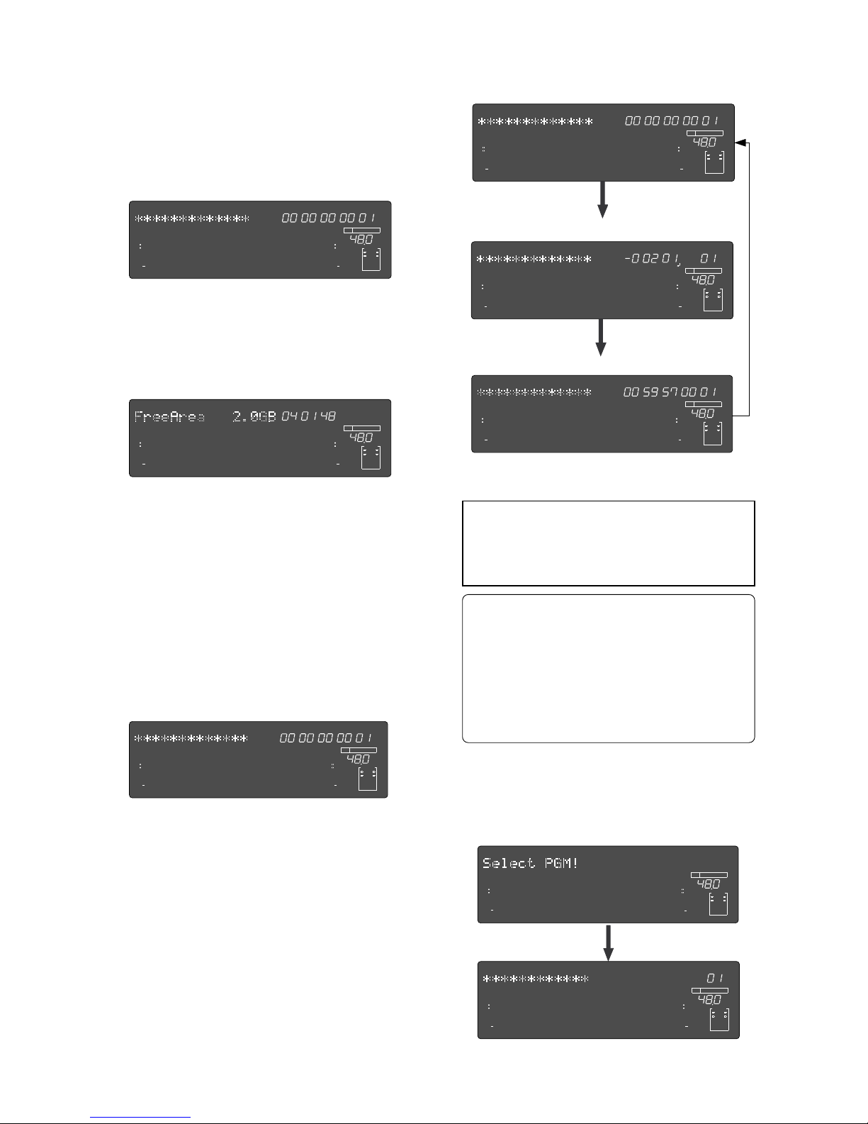
Model D2424LVmkII Reference Manual (Names and Functions)
22
Pressing the [PGM SEL] key will cause the recorder
to enter Program select mode, display the message
“Select PGM !”, followed by the current Program
and Program number and a flashing “SURE?”
indication.
* About the Program Change function
The Program Change function divides the hard disk
space into up to 99 parts to accommodate 99
separate Programs (P01-P99 - as long as available
recording time allows) so you can record, play back,
edit, and reachieve (save and load) data for each
Program individually. For example, the first song
can be Program 1, the second song can be Program
2, etc. You need to recall the desired Program before
you start recording, playback, editing, or reachieving.
5. Changing Programs using the [PGM SEL] key
ABS time base
BAR/BEAT/CLK time base
MTC time base
4. Switching the Time Base display using the
[SHIFT] key and [DISP SEL] key
When the screen is showing the ABS TIME or
REMAIN display, if you press the [DISP SEL] key
repeatedly while holding down the [SHIFT] key,
the TIME BASE display will change cyclically.
You can select one of the following Time Base
displays.
If “BAR/BEAT/CLK” is selected for the time base
(explained later), the DISK REMAIN indication will
show a value (in terms of the number of
measures) calculated based on the last beat/
tempo data on the tempo map of the recorded
song.
At this time if you press the [DISP SEL] key, the
Disk Remain display will appear. (Both recordable
time and hard disk capacity remaining will be
converted to mono track and expressed in time
and megabytes.)
ABS TIME display
DISK REMAIN display
If you press the [DISP SEL] key again, the MTC IN
display will appear. If an optional Model 8346
TC/SYNC card is installed, and the reference TC
is switched to "LTC", and an external TC is input,
that reference input LTC time figure will be
displayed.
MTC IN display
3. Switching the display using the [DISP SEL] key.
Let’s assume that you turned off the power while
the time display was using a time base of “ABS,”
and then you turned the power on again.
The recorder time display will again use a time
base of “ABS.”
If you press the [DISP SEL] key again, the screen
will return to the “ABS TIME” display.
SMH
∞
42
OL
0
30
24
18
12
9
6
3
kHz
24
FS
BIT
PGM
24
∞
42
OL
0
30
24
18
12
9
6
3
ABS
232221201918
17
16151413121110
98765
4
3
2
1
CLOCK
INT
SMH
∞
42
OL
0
30
24
18
12
9
6
3
kHz
24
FS
BIT
PGM
24
∞
42
OL
0
30
24
18
12
9
6
3
MTC IN
232221201918
17
16151413121110
98765
4
3
2
1
CLOCK
INT
SMH
∞
42
OL
0
30
24
18
12
9
6
3
kHz
24
FS
BIT
PGM
24
∞
42
OL
0
30
24
18
12
9
6
3
ABS
232221201918
17
16151413121110
98765
4
3
2
1
CLOCK
INT
BAR
∞
42
OL
0
30
24
18
12
9
6
3
kHz
24
FS
BIT
PGM
24
∞
42
OL
0
30
24
18
12
9
6
3
232221201918
17
16151413121110
98765
4
3
2
1
CLOCK
INT
SMH
∞
42
OL
0
30
24
18
12
9
6
3
kHz
24
FS
BIT
PGM
24
∞
42
OL
0
30
24
18
12
9
6
3
MTC
232221201918
17
16151413121110
98765
4
3
2
1
CLOCK
INT
∞
42
OL
0
30
24
18
12
9
6
3
kHz
24
FS
BIT
SETUP
24
∞
42
OL
0
30
24
18
12
9
6
3
232221201918
17
16151413121110
98765
4
3
2
1
CLOCK
INT
∞
42
OL
0
30
24
18
12
9
6
3
kHz
24
FS
BIT
PGM
24
∞
42
OL
0
30
24
18
12
9
6
3
SURE?
232221201918
17
16151413121110
98765
4
3
2
1
CLOCK
INT
SMH
∞
42
OL
0
30
24
18
12
9
6
3
kHz
24
FS
BIT
24
∞
42
OL
0
30
24
18
12
9
6
3
REMAIN
232221201918
17
16151413121110
98765
4
3
2
1
CLOCK
INT
<Note>:
Such operations as program compilation
and selecting, will only functions when the "
Chain
Play?
" menu in the SETUP mode is "
Off.
"
In regards to the "
Chain Play?
" menu in the SETUP
mode, see page
61
.
Page 23
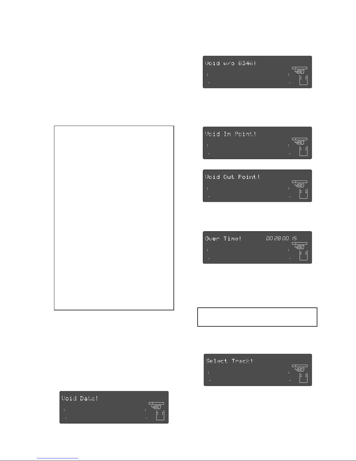
Model D2424LVmkII Reference Manual (Names and Functions)
23
6. Warning messages
If you perform an incorrect operation, input
incorrect data, or if an error occurs, the following
alarm indication appears:
• Invalid data indication:
The input data is not appropriate for the operation.
• Invalid In/Out indication:
The In or Out point is not appropriate for the operation.
You can select the desired Program from the already
setup Programs by rotating the Jog dial while the
Program number and “SURE?” are flashing.
After you select a Program, press the [EXECUTE/YES]
key to return to the selected Program’s ABS
indication.
The Time Base display will indicate the selected
Program’s Time Base, since you can set the Time
Base for each Program individually.
To change the Time Base display after you have
selected the desired Program, press the [DISP SEL]
key while holding down the [SHIFT] key.
Pressing only the [DISP SEL] key will take you to the
REMAIN display based on the current Time Base.
<Notes>
• The maximum record time of the program is
dependent on the permissible record time (size)
of the hard disk, regardless of how many
programs are created on the disk. If, for example,
there is roughly 30 minutes of record time
remaining (REMAIN) on the current drive
immediately after it is formatted, and a 20 minute
program is recorded in Program 1, then there is
only 10 minutes of recording time remaining for
any additional programs.
Simply put, if the total record time is 30 minutes
it does not matter whether the 30 minutes is taken
by 1 program or shared among several programs,
since the total of 30 minutes for a recording
remains the absolute total.
Note that some disk space is compensated when
several programs are created on the disk.
A new program cannot be created when there is
no recordable space remaining on the disk.
However, programs produced by "Program
duplicating" are exempted.
• For initial setup, when producing a new program,
the initial setting of the currently active program
is directly copied. For example, if there is a
randomly set tempo map in the current program,
that tempo map setting will be copied as the
tempo map for the new program.
This is convenient for producing a new program
with the same setting as previously made music.
• Display of void:
This is displayed if you attempt some sort of process
for which the optional Model 8346 TC/SYNC card is
necessary and is not installed.
• Action to take:
Input correct data.
• Action to take:
Input correct data.
∞
42
OL
0
30
24
18
12
9
6
3
kHz
24
FS
BIT
24
∞
42
OL
0
30
24
18
12
9
6
3
232221201918
17
16151413121110
98765
4
3
2
1
CLOCK
INT
∞
42
OL
0
30
24
18
12
9
6
3
kHz
24
FS
BIT
24
∞
42
OL
0
30
24
18
12
9
6
3
232221201918
17
16151413121110
98765
4
3
2
1
CLOCK
INT
∞
42
OL
0
30
24
18
12
9
6
3
kHz
24
FS
BIT
24
∞
42
OL
0
30
24
18
12
9
6
3
232221201918
17
16151413121110
98765
4
3
2
1
CLOCK
INT
∞
42
OL
0
30
24
18
12
9
6
3
kHz
24
FS
BIT
24
∞
42
OL
0
30
24
18
12
9
6
3
232221201918
17
16151413121110
98765
4
3
2
1
CLOCK
INT
• Overtime indication:
Available disk space is insufficient for the length of time
(the number of measures) indicated on the display.)
• Action to take:
During the copy & paste and move & paste operation,
try to shorten the length of the copied data by the
indicated amount. Alternatively, use the “ERASE”
function to move the ABS END point backward to obtain
enough disk space for editing.
<Note>:
Optimizing the disk is necessary in the
current drive in which multiple undo is ON.
FSMH
∞
42
OL
0
30
24
18
12
9
6
3
kHz
24
FS
BIT
24
∞
42
OL
0
30
24
18
12
9
6
3
232221201918
17
16151413121110
98765
4
3
2
1
CLOCK
INT
• Unassigned track indication:
Select any track.
• Action to take:
Use the [RECORD TRACK] select key to ready any track.
∞
42
OL
0
30
24
18
12
9
6
3
kHz
24
FS
BIT
24
∞
42
OL
0
30
24
18
12
9
6
3
232221201918
17
16151413121110
98765
4
3
2
1
CLOCK
INT
Page 24
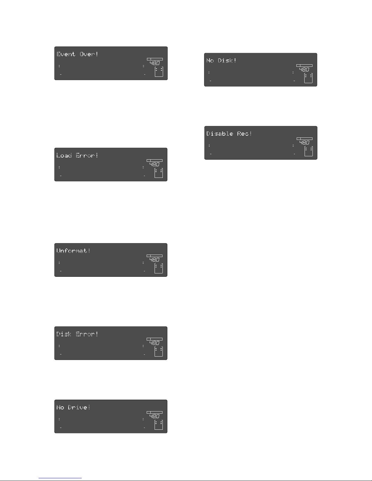
Model D2424LVmkII Reference Manual (Names and Functions)
24
• Event overflow indication:
The editing points have overflowed.
• Load error indication:
You cannot load data because the data input to the
[DATA INPUT] connector contains an error.
• Un-formatted indication:
The internal hard disk is damaged or not formatted
yet. After this message is shown for about 10 seconds,
“Disk Format ?” in Setup mode will flash on the display.
• Action to take:
After temporarily saving the data to the CompactFlash
card via the SETUP mode "Save PGM?" menu, return
the data to the recorder by the same SETUP mode "Load
PGM?" menu. The editing number of points will be
cleared and you can continue editing.
• Action to take:
Check to see if there is an abnormality with the external
digital machine connected to the [DATA INPUT]
connector, or cable. Try to “LOAD” again.
• Action to take:
Press and hold down the [RECORD] button and press
the [EXECUTE/YES] key to format the disk. (All audio
and other data on the disk will be lost.)
• Disk error indication:
This disk cannot be read.
• Action to take:
Contact the Fostex service station as soon as possible.
• Hard disk (E-IDE) connection error:
The hard disk is not connected correctly.
• No disk error display:
This is displayed when the removable disk is incorrectly
set in the CompactFlash
TM
card.
• Recording Disable:
Recording is disabled.
• Action to take:
Correctly set the E-IDE hard disk again.
• Action to take:
Reset the removable disk.
• Action to take:
Change the “Off” (recording) “Rec Protect ?” setting in
Setup mode.
∞
42
OL
0
30
24
18
12
9
6
3
kHz
24
FS
BIT
24
∞
42
OL
0
30
24
18
12
9
6
3
232221201918
17
16151413121110
98765
4
3
2
1
CLOCK
INT
∞
42
OL
0
30
24
18
12
9
6
3
kHz
24
FS
BIT
24
∞
42
OL
0
30
24
18
12
9
6
3
232221201918
17
16151413121110
98765
4
3
2
1
CLOCK
INT
∞
42
OL
0
30
24
18
12
9
6
3
kHz
24
FS
BIT
24
∞
42
OL
0
30
24
18
12
9
6
3
232221201918
17
16151413121110
98765
4
3
2
1
CLOCK
INT
∞
42
OL
0
30
24
18
12
9
6
3
kHz
24
FS
BIT
24
∞
42
OL
0
30
24
18
12
9
6
3
232221201918
17
16151413121110
98765
4
3
2
1
CLOCK
INT
∞
42
OL
0
30
24
18
12
9
6
3
kHz
24
FS
BIT
24
∞
42
OL
0
30
24
18
12
9
6
3
232221201918
17
16151413121110
98765
4
3
2
1
CLOCK
INT
∞
42
OL
0
30
24
18
12
9
6
3
kHz
24
FS
BIT
24
∞
42
OL
0
30
24
18
12
9
6
3
232221201918
17
16151413121110
98765
4
3
2
1
CLOCK
INT
∞
42
OL
0
30
24
18
12
9
6
3
kHz
24
FS
BIT
24
∞
42
OL
0
30
24
18
12
9
6
3
232221201918
17
16151413121110
98765
4
3
2
1
CLOCK
INT
Page 25
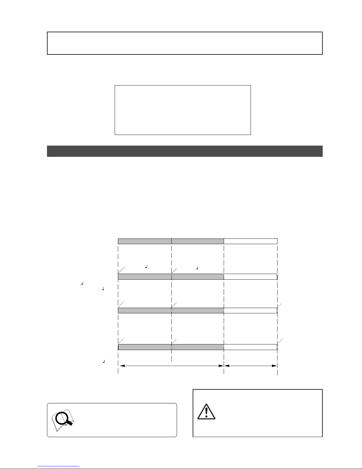
25
Model D2424LVmkII Reference Manual (Before Starting)
Recorded area
Non recorded area
ABS 0
00 m, 00 s, 00 f
00 m, 08 s, 00 f REC END
DISK END
23 h, 59 m, 59 s
-002 bar, 1
, 00 clk
001 bar, 1
, 00 clk
01 h, 00 m, 00 s, 00 f
01 h, 00 m, 08 s, 00 f
00 h, 59 m, 52 s, 00 f
01 h, 00 m, 00 s, 00 f
00 h, 59 m, 51 s
00 h, 59 m, 59 s
ABS
BAR/BEAT/CLK
MTC
MTC
BAR = 001bar, 0404
TEMPO=001bar, 1
, 60
MTC OFFSET=01h, 00m, 00s, 00f
MTC OFFSET MODE=ABS
(This shall be assumed to be the
MTC OFFSET time set for the ABS
00m, 00s, and 00f positions.)
MTC OFFSET=01h, 00m, 00s, 00f
MTC OFFSET MODE=Bar
(This shall be assumed to be the MTC
OFFSET time set for the 00 bar, 1
beat, and 00 clk positions.)
Before Starting
This chapter describes some basic items that you need to know before you start operating the
recorder. All users, including those who are familiar with using tape-based multitrackers and those
who are new to multitrackers, should read this chapter thoroughly to understand the functions of
the recorder.
1. Time Base
2. Recording method and REMAIN indicator
3. Managing songs b y Pr ogram Change function
4. Real tracks and Ad ditional trac ks
5. Input monitoring and playbac k monitoring
6. Audio file and Event
Time Base
The word “Time Base” appears frequently in this manual. The concept of Time Base is similar to a “tape
counter” on a conventional tape-based multitracker in that it indicates the precise position of the recorder
transport section (the current position).
The recorder offers three types of Time Base: ABS (Absolute type), MTC (MIDI time code), and BAR/BEAT/CLK
(bar/beat/clock). ABS indicates an absolute time on the disk. MTC indicates a relative time that is obtained
by adding a certain value (MTC offset value) to the ABS value. BAR/BEAT/CLK indicates the position in a song
created in the internal Tempo Map according to MIDI clock and Song Position Pointer. The following diagrams
depict the relationship among these three types of the Time Base.
You can switch between these three types
of Time Base to suit your purpose. (Refer
to the explanation in “Display Section” on
page “
22
” for more information on
switching Time Base.)
<Note>:
As shown in the figure, the ABS 0
position (top of the disk) is [-2 bar, 1 beat,
00 clk] (Time Base-BAR/BEAT/CLK). You can
change this position in the ranged -9 bar to
-2 bar in the “Setting the time signature”
menu. Refer to the “Setting the time
signature menu” section on page “
108
”.
Page 26
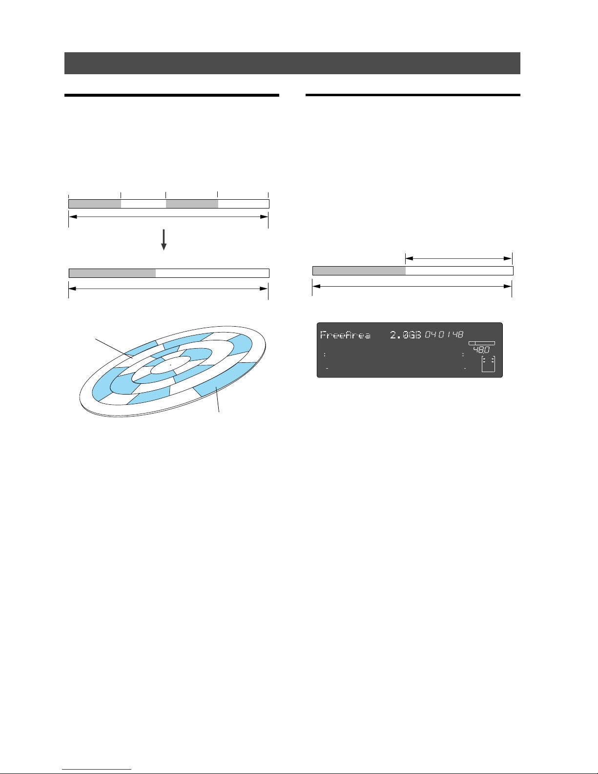
26
Model D2424LVmkII Reference Manual (Before Starting)
The REMAIN indicator displays the
amount of unrecorded area.
recordable disk area (3 hours)
recorded area (11min. 03sec.) unrecorded area (2 hour 48 min. 57 sec.)
ABS 0
23h, 59m, 59s
03m 00s 00f 10m 00s 00f
12m 00s 00f
unrecorded area
unrecorded area
recorded area (3 min.)
recorded area (2 min.)
You can record at any point within 24 hours in ABS time.
REC END
The area actually used on the disk.
recordable disk area (e.g.: 30 minutes)
recorded area (5 min.) unrecorded area (25 min.)
You can record at any point within 24 hours in ABS time.
<Display example>
Gray areas are recorded areas.
White areas are unrecorded areas.
Recording method and REMAIN indicator
Recording method
The recorder uses a E-IDE hard disk instead of a
cassette tape. You can start recording sound sources
from any point on a formatted disk as long as the
point is within the range of 24 hours in ABS time, as
described in the previous “Time Base” section. (Refer
to the following diagram.)
For example, if you record three minutes of data
starting from ABS 0 (top of the disk) to ABS 03M
00S 00F on a disk that has a recordable space of
thirty minutes, as shown in the diagram, then if you
record two minutes starting at the 10-minute point
in ABS time (ABS 10M 00S 00F) to ABS 12M 00S 00F,
the recording end point (REC END) is 12 minutes
(ABS 12M 00S 00F) in ABS time. However, this does
not mean that the entire recording duration is 12
minutes. The disk space actually used for recording
is five minutes (3 minutes + 2 minutes).
That is, the area between three minutes and ten
minutes (that corresponds to 25 minutes of
recording space) in terms of ABS time is still
unrecorded.
When you try to play or fast forward this unrecorded
area, the time counter on the display will count, but
the recorder will not access the disk. However, MTC
will be output when you try to play this area.
On the recorder, the top of the disk is called “ABS 0”
and the recording end point is called “REC END.”
REMAIN indicator
The REMAIN indicator displays available recording
time expressed in time value (ABS or MTC) or bar/
beat/clock (BAR/BEAT/CLK) value, depending on the
currently selected Time Base.
It also indicates the available disk space. Right after
you format the disk, the REMAIN indicator will show
the maximum recordable time and space on the disk.
The following example shows that the disk had about
3 hours recordable space after the disk format
operation, and has recorded data of 2 hours 48
minutes 57 seconds.
The REMAIN value is calculated on a mono-track
basis. That value indicates the available recording
time and space if you record on one mono-track.
For example, if you wish to know how much you
can record on eight tracks, you need to divide the
current REMAIN value by eight.
The REMAIN value display is calculated from data
on the real track and data on the additional track
which will be explained later, and includes data left
over for multiple undo. In other words, the REMAIN
value will be displayed in the form of time/capacity
obtained by deducting data on the real track, data
moved onto the additional track and past editing
data left over for multiple undo.
As described in “Managing the song by Program,” the
recorder can set up as many as 99 Programs on the
disk. Setting up a Program requires a small amount
of disk space. In other words, disk space is used not
only for storing recorded data but also for storing
all setup data. Therefore, make sure that you have
enough space on the disk before you start recording
to avoid running out of space (the “OVER!” message
flashes in that case).
SMH
∞
42
OL
0
30
24
18
12
9
6
3
kHz
24
FS
BIT
24
∞
42
OL
0
30
24
18
12
9
6
3
REMAIN
232221201918
17
16151413121110
98765
4
3
2
1
CLOCK
INT
Page 27
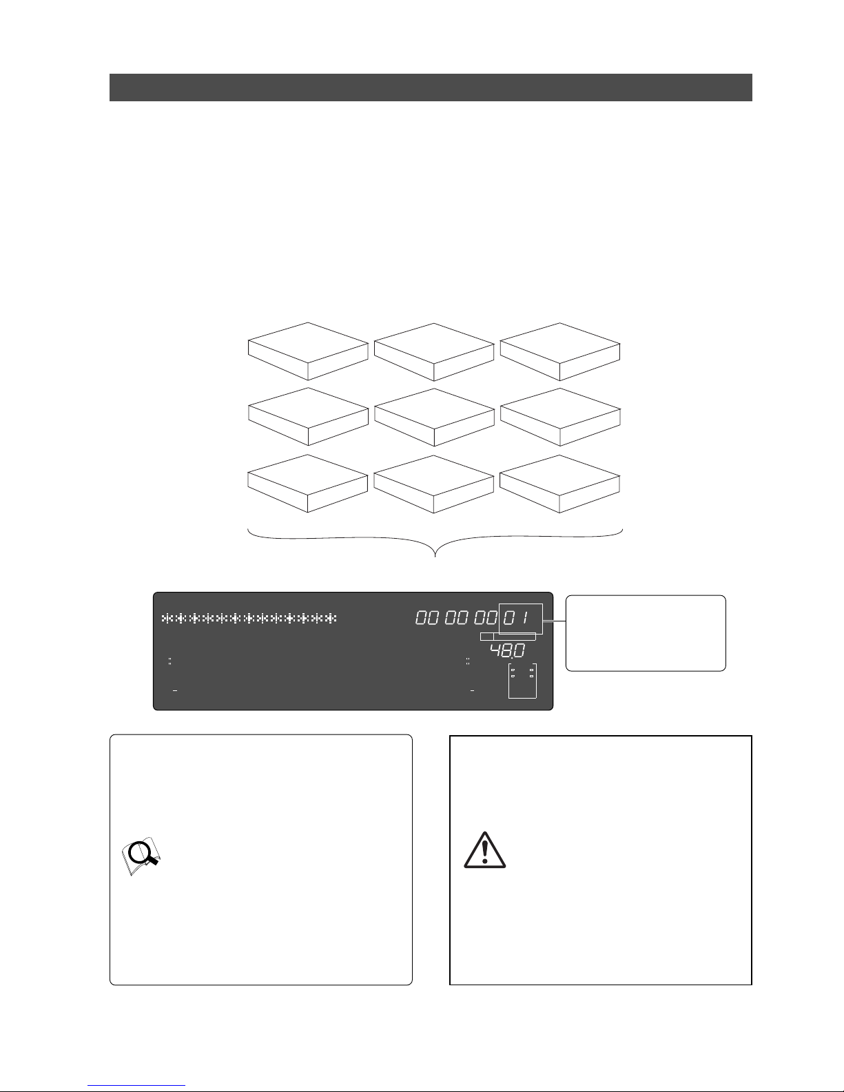
27
Model D2424LVmkII Reference Manual (Before Starting)
Managing songs by Program Change function
The recorder feature a Program Select function, which enables you to set up to 99 Programs on the disk.
When you format a disk, one Program is automatically created on the disk. You may create more Programs, if
necessary. You may also delete unnecessary Programs.
The recorder also features Program Change function, which enables you to select one of the Programs set on
the disk. Programs on the disk are something like independent containers. You can record, play, and edit
each container without affecting other containers. You can also name Programs, which is useful for managing
songs.
Additionally, as the sampling frequency can be changed individually for each program that is generated,
programs with different FS can be contained in one current drive.
NOTE:
The ability to change the FS is limited by the quantizing figure used at formatting.
This is the Program indication
when using an E-IDE hard disk as
the current drive ([PGM] will
appear before the program
number such as [P01] shown in
the example below).
• Refer to page “40” for more information on
the program select function.
• Refer to page “
39
” for more information on
the duplicating a program.
• Refer to page “
40
” for more information on
the program delete function.
• Refer to page “
41
” for more information on
the editing a program title.
• In regards to the "Chain Play?" menu in the
SETUP mode, see page “
61
”.
• Refer to page “
42
” for “Changing the
program FS.”
<Notes>
• Total available recording time is always
the maximum available recording time on
the disk, regardless of the number of
Programs you set on the disk. That is, if
you use up the maximum recording time
for one Program, you will not be able to
record any data in other Programs.
• As described in the “
REMAIN indicator
,”
creating additional Programs will consume
a small amount of disk space.
•
Such operations as program compilation
and selecting, functions only when the
"
Chain Play?
" menu in the SETUP mode, is
"
Off.
"
program 1
program 2
program 3
program 4
program 5
program 6
program 7
program 8
program 9
You can set up to 99 programs (independent containers).
SM
∞
42
OL
0
30
24
18
12
9
6
3
kHz
24
FS
BIT
PGM
24
∞
42
OL
0
30
24
18
12
9
6
3
ABS
2322
21
20
19
18
17
1615141312
11
10
98765
4
3
2
1
CLOCK
INT
Page 28
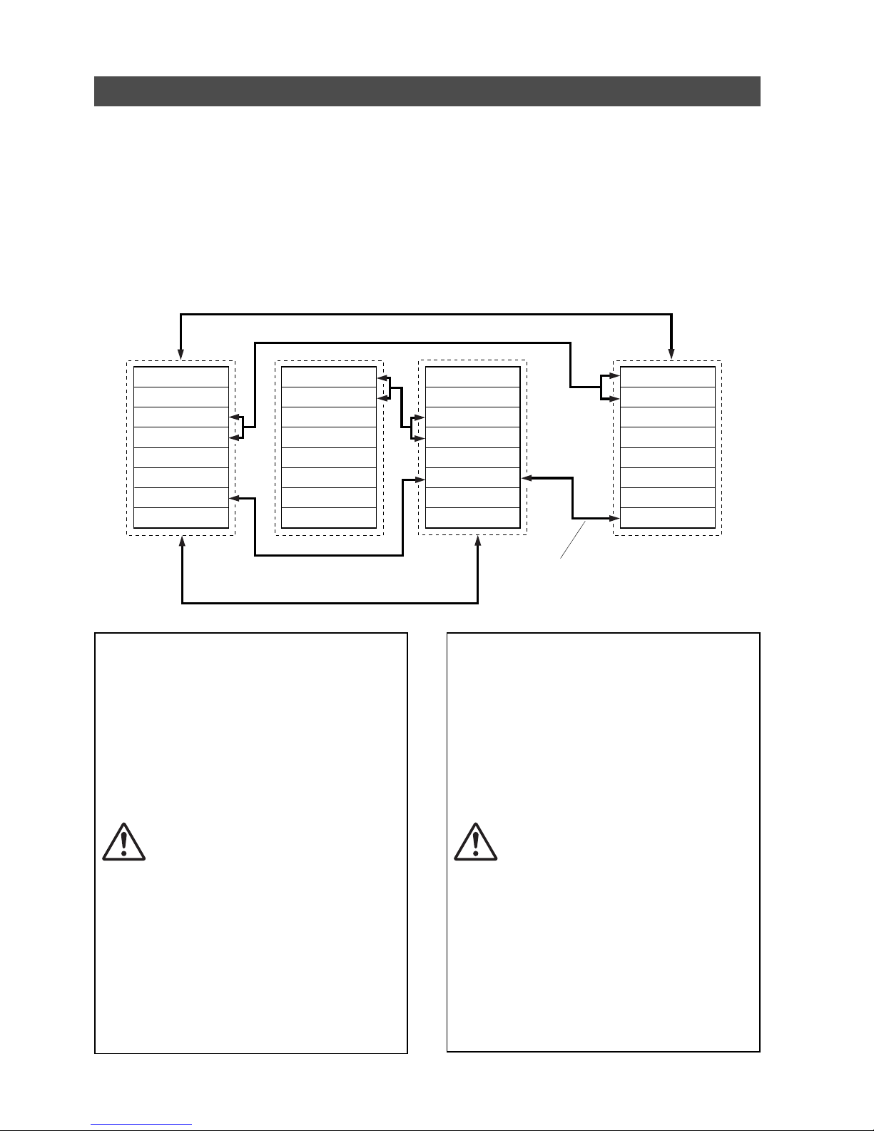
28
Model D2424LVmkII Reference Manual (Before Starting)
Real tracks and Additional tracks
The D2424LVmkII contains, in addition to 24 real tracks that can be recorded/played back/edited in real time
as one program, 32 additional tracks (In the current drive formatted at 96kHz/24bits or 88.2kHz/24 bits, it
will be 8 real tracks + 48 additional tracks.).
Real tracks are normally used for real time recording of sound sources and the additional tracks serve the
purpose of temporarily storing the sound recorded on the real tracks. In other words, by temporarily moving
data recorded in the real track to an additional track, another performance can be recorded on the empty real
track.
To exchange real tracks with additional tracks, the D2424LVmkII contains a "Track exchange function."
By using this function, exchange is possible between all tracks, for mono tracks, stereo pair tracks (2 tracks)
and in groups of 8 track units.
<Notes>
• The “
Format conversion of the additional track
”
menu is contained in the SETUP mode of this
recorder.
Using this menu, it is possible to convert or
reverse convert, the additional track format
of the current drive presently in use to the
“
V2 (56)
” format (real track + additional track
= 56).
With this menu, the additional track format
of the current drive presently in use can be
converted or reverse converted from the
“
V2 (56)
” format (real track + additional track
= 56) to the “
V1 (24)
” format (real track +
additional track = 24).
What this menu is that hard disk
compatibility is possible between the
“
V2 (56)
” format D2424/D824mkII /
D1624mkII and the “
V1 (24)
” format D824/
D1624.
In other words, a hard disk recorded in
“
V2 (56)
” format equipment can be used in
“
V1 (24)
” format equipment, or the reverse.
However, care must be taken when
converting the format. Refer to the SETUP
mode in page “
127
” for details.
• Track composition of a D2424LVmkII
formatted in 96kHz/24bit or 88.2kHz/24bit
will be 8 Real Tracks + 48 Additional Tracks.
<Notes>
• You cannot record data on Additional tracks
in real-time. Also, you cannot play back data
on Additional tracks as is in real-time.
If you wish to play back data on an
Additional track, first use the Track Exchange
function to move the data to a Real track.
Also, you need to move the data to a Real
track if you wish to check the REC END point
of a song on an Additional track. Refer to
page “
77
” for more information on the Track
Exchange function.
• Data on the Additional tracks also affects the
REMAIN value. If Real tracks contain no data,
but Additional tracks contain data, the
amount of data (time and space) will be
reflected in the REMAIN value.
• If the record time of the data existing on the
additional track is longer than the data on
the real track and all tracks are saved on an
external DAT or adat, then the data of the
additional track can only be saved for the
time equal to the real track, and the
remaining data is not saved. This is because
the ABS 0 to REC END of the real track is
automatically recognized and saved.
There is a need to exchange the track using
the track exchange function in this case, as
well. Refer to page “
90
” for more information
on the SAVE/LOAD function.
Track 1
Track 2
Track 3
Track 4
Track 5
Track 6
Track 7
Track 8
Track 9
Track 10
Track 11
Track 12
Track 13
Track 14
Track 15
Track 16
Track 17
Track 18
Track 19
Track 20
Track 21
Track 22
Track 23
Track 24
Track 49
Track 50
Track 51
Track 52
Track 53
Track 54
Track 55
Track 56
.........................
Exchange in 8 track units
Exchange in 8 track units
Exchange in mono track units Exchange in mono track units
Exchange in 2 (stereo pair) track units
Page 29
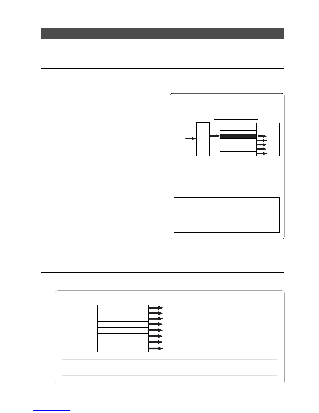
29
Model D2424LVmkII Reference Manual (Before Starting)
Input monitoring and playback monitoring
There are two methods for monitoring track sound (only on the Real tracks): input monitoring and playback
monitoring. They are defined as follows:
Input monitoring
Input monitoring means to listen to what is being input to the recorder so that you can verify sound
quality and etc. Either one of the following procedure is used to input monitor any Real Track or all
Real Tracks.
• Entering any Real Trac k to input monitoring
To enter any desired track for Input Monitoring, press
the desired [RECORD TRACK] select key to enter it in
the READY mode and then press the [RECORD] button.
If the [RECORD] button is pressed again, the recorder
will enter the repro mode. The recorder will enter
record standby mode and the READY track only will
be Input Monitoring.
The recording level can now be adjusted.
• Entering all Real Tracks to input monitoring
To enter all Real Tracks to input monitoring, press
the [TRACK SHIFT] key while holding down the [SHIFT]
key.
Unlike the previous case of selecting any desired track,
Real Tracks can all be input monitored even though
the [RECORD] button is not pressed. After adjusting
the recording level, to simultaneously start recording
all tracks, enter all tracks in the READY mode by
pressing the [RECORD] button while holding down the
[SHIFT] key.
• Entering a track set to Input Monitoring to
“recording mode”
To enter the recording mode with any desired track
or all tracks in the READY state, press the PLAY button
while holding down the [RECORD] button.
READY tracks will enter the recording mode, the
READY track LED change to constant light and the
RECORD LED will be lit.
Simultaneous with entering the recording mode,
READY tracks will be input monitoring and recording
can be done while monitoring the recording sound at
the recorder output.
* The following example shows track 5 in Input
Monitoring mode and other tracks in Playback
Monitoring mode.
Playback monitoring
“Playback monitoring” means to monitor the playback sound of the tracks (only Real tracks).
That is, you are monitoring the playback sound on the track, not the sound being recorded to the track.
* The following example shows that all tracks are in Playback Monitoring mode.
In this example, all tracks 1-8 are playing
the recorded sound in Playback Monitoring
mode.
* To play the sound on an Additional track, you need to move the data from the Additional track to a
Real track. Refer to “Trac k Exchange function” on page “77” for more information.
Track 1 (Drum machine)
Track 2 (Bass)
Track 3 (Guitar)
Track 4 (Vocal)
Track 5
Track 6
Track 7
Track 8
Mixer section
Recorder section
Monitoring
section
Keyboard
Track 1 (Drum machine)
Track 2 (Bass)
Track 3 (Guitar-1)
Track 4 (Guitar-2)
Track 5 (Vocal)
Track 6 (Vocal)
Track 7 (Keyboard)
Track 8 (Piano)
Recorder section
Monitoring
section
This example shows overdubbing in which the keyboard is
recorded on track 5 while tracks 1-4 are being played.
Tracks 1-4 are in Playback Monitoring mode and used to check
the playback sound. Track 5 is in Input Monitoring mode.
You can monitor the recorded sound.
<Note>:
When in the "
Auto EE MD?
" menu of the
D2424LVmkII SETUP mode, the all input monitor
mode can be entered automatically when
D2424LVmkII stops.
For details, refer to the SETUP mode "
Auto EE MD?
"
menu in page
122
.
Page 30
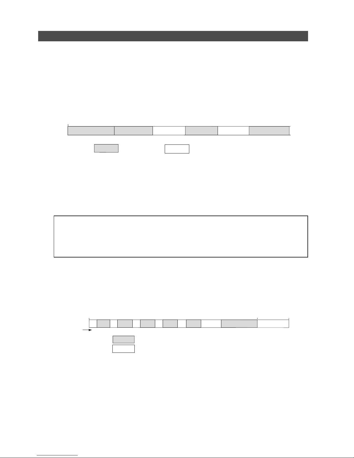
30
Model D2424LVmkII Reference Manual (Before Starting)
Audio file and event
<About an audio file>
During recording, the recorder consecutively records an independent audio file (recorded area) in each
track of each Program. However, you can record data on the recorder at any point within 24 hours of
ABS time, and you can intentionally create silence between two audio files. In this case, a silent part is
counted as a 0 file.
Therefore, audio files and 0 files are consecutively created as shown in the diagram below.
The total number of these audio files and 0 files is called “the number of events.” The maximum number
of events is 512 per track (tracks 1-24). After the number of events reaches 508, new data will not be
recorded.
Usually, an event is created by one recording or edit. The number of events increases or decreases
depending on the number of edit points or the amount of disk free space. (The recorder disk management
operates in such way that the number of events will decrease.) The number of events does not affect
usual music production. However, if a small amount of single-track data is written in many different
sections on the disk, the maximum number of events may be reached. To avoid this “event number
overflow,” you need to check the number of events for each track.
The recorder provides an event check menu in Setup mode for this purpose.
<Notes on digital recording>
During analog recording, “
0 files
” are not created since silence does not create “
data 0
.”
However, during S/P DIF and adat digital recording, the recorder records “
data 0
” (this is called “mute recording”).
When one second of consecutive data 0 is input to the recorder, it creates a “
0 file
” and limits the consumption
of disk space. However, repeating this operation will eventually increase the number of events, leading to “
event
number overflow
.”
What is an event?
As shown in the diagram below, the number of events can be eleven or more if partial recordings are
made. This is because an unrecorded part is regarded as an event, and a recorded part is also regarded
as an event(s). The duration of each event can vary from 740 msec to 23 hours 59 minutes 59 seconds
(FS =44.1kHz).
An unrecorded part (zero file) is always regarded as one even, regardless of its duration.
However, a recorded part can consist of a group of multiple audio file, as shown in the diagram below.
More precisely, one audio file will be divided into multiple audio files if perform many editing operations
(such as , copy & paste, move & paste, etc.) on this audio file.
Multiple audio files created in this way are regarded as events. (If you do not edit the data at all, the
audio file remains in one piece and is regarded as one event.)
In this example, one recorded area consists of six consecutive audio files. This means that this part
consists of six events.
ABS 0
REC END
Recorded part
Silence
Audio File 1 Audio File 2 Audio File 3
Audio File 40 File 1 0 File 2
ABS 0
REC END
Recorded part (shortest: 740 msec., FS=44.1kHz)
Unrecorded part (shortest: 740 msec., FS=44.1kHz)
ABS 23h 59m
0
12 34 5 67
89
10
11
Event Number
Page 31
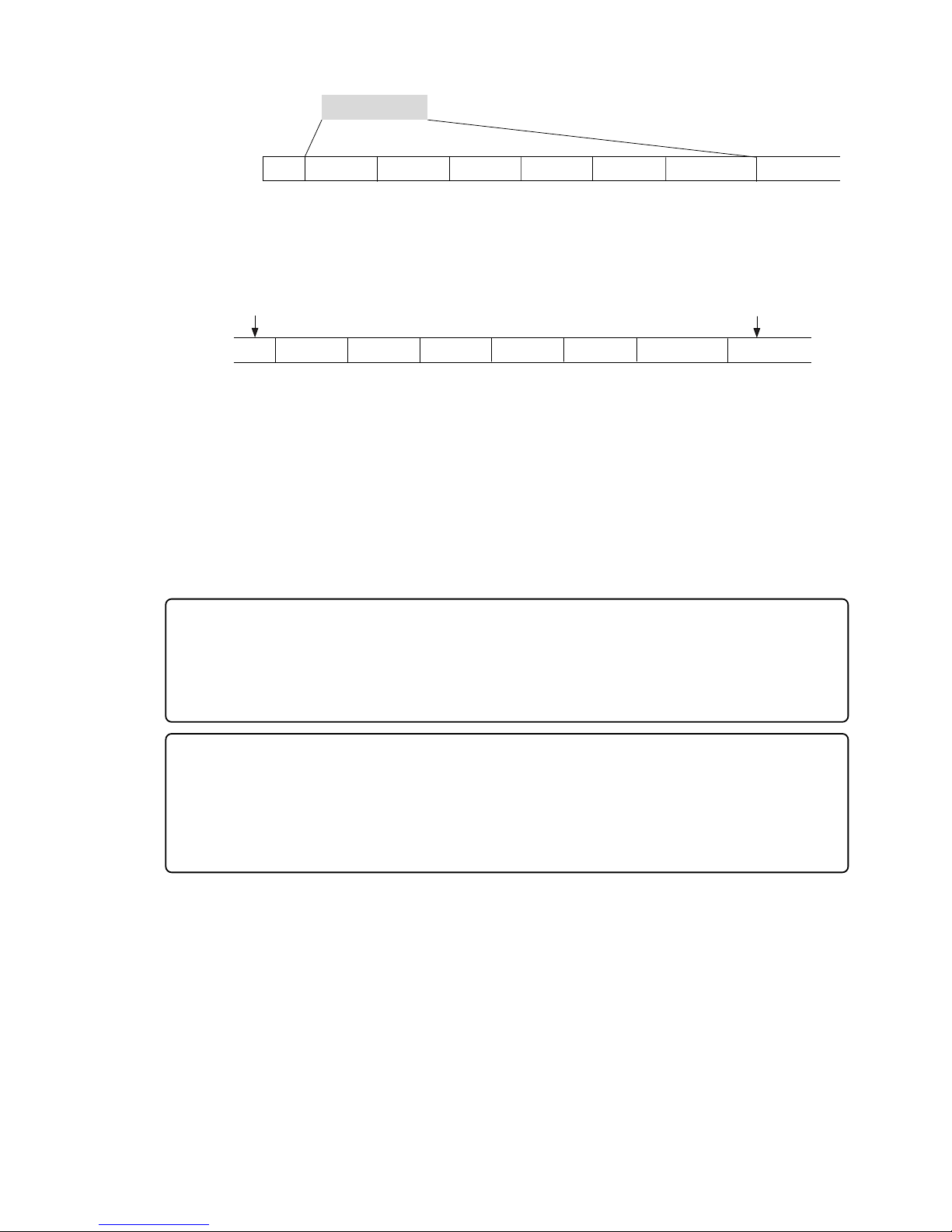
31
Model D2424LVmkII Reference Manual (Before Starting)
<Hints>
Make sure that you set the Clipboard In/Out points within zero files, and that you paste the area
starting from the same Clipboard In point.
* In any case, bear in mind that you cannot reduce the excessive number of events if the target
range contains a zero file.
This is because when you perform a copy & paste, move & paste, or Auto Punch In/Out, the event is split
at the edit point. Also, if a continuous long recording is made, the recorded data might scatter to
different locations on the hard disk, thus dividing the data unto multiple events.
Countermeasures against accumulating too many events due to a long recording plus many editing
operations:
One solution is to save and re-load the data to and from a DAT, adat, or a CompactFlash
TM
card. (If the
song is too long, you may not be able to save the data to a DAT or adat.)
In this way, multiple consecutive audio files are optimized into one continuous audio file in some cases.
Set the Clipboard In point and the Clipboard Out points within an unrecorded range to copy the area
(the area that contains multiple audio files and you wish to optimize) between them, then paste the data
starting from the same Clipboard In point. Multiple audio files within this range will become a single
audio file.
0 File
Audio File 1
Audio File 2
Audio File 4
Audio File 3
Audio File 5
Audio File 6
0 File
n+1 n+2
n+3
n+4
n+5
n+6
Recorded Area
Event Number
0 File
Audio File 1
Audio File 2
Audio File 4
Audio File 3
Audio File 5
Audio File 6
0 File
n+1 n+2
n+3
n+4
n+5
n+6
CLIPBOARD IN point
CLIPBOARD OUT point
Event Number
<Setup to writable/not writable of the “0 file”>
There is menu for writing or not of the “0 file” in the SETUP mode of this recorder.
At the initial setup, it is set to “Writing in the 0 file (Enable)” but by changing this to “Not writing in the
0 file (Disable),” writing the “0 file” in the disk can be stopped.
By doing so, the above mentioned “event over” can be prevented. For details, refer to SETUP mode
in page “121.”
Page 32
32
Model D2424LVmkII Reference Manual (Formatting and Optimizing Disks)
Formatting and Optimizing Disks
Quantization
Sampling Frequency
16 bits
44.1kHz 48kHz 96kHz
24 bits 16 bits 24 bits 24 bits
Multiple Undo
Function
On
Off
24 real tracks + 32 additional tracks
Track architecture
Format Type
Standard Format
(Default Setting)
Quick Format
8 real tracks
+
48 additional tracks
Recording
Save/Load
Erase Format
This section describes how to format and optimize a current drive disk and a backup disk.
You can also find information regarding formatting and optimizing the disks in the Quick Operation
Guide and in the “Saving and Loading Song Data” section of this manual.
Formatting a current drive disk
Before you format a current drive disk, specify the sampling frequency and bit (data) resolution,
Multiple Undo on/off, and format type parameters. Refer to the table below for more information
on these settings.
<Detailed formatting parameters>
Turn this function on to use the Multiple Undo function for all takes (recordings and edits).
This function consumes more disk space. If you are using a small capacity disk, tur n this
function off.
Turn this function off to use the undo/redo function only for the current take (recording or edit).
If the capacity of the current drive disk is small, turn this function off.
The recorder formats a disk while evaluating the integrity of the disk, including the access time
for each block on the disk. Time required for formatting is longer, but you can be sure of a
highly reliable format. Ordinar ily, this format type is selected. This option is displayed and
accessible whether you format a new disk or reformat an old disk.
With this simple format type, the recorder assumes that all sectors on the hard disk are of
good quality . Time required f or formatting is shorter, b ut any bad sectors would not be detected.
Select this format type when you format a brand new disk for which Fostex has confirmed
quality operation. You can select this format type only when you format a new disk or reformat
a disk previously formatted with Quick F ormat.
Y ou can select this f ormat type only when you reformat a disk previously f ormatted with Standard
Format. Use of this f ormat will erase all data on the disk while keeping the Standard Format.
Time required for formatting is shorter than when using Standard Format.
• 24-track simultaneous analog recording
• 24-track simultaneous analog (22 tracks) and digital (2 tracks
-S/P DIF) recording
• 24-track simultaneous analog (16 tracks) and digital (8 tracks
- adat) recording
• 24-track simultaneous adat digital recording
• 8-track simultaneous analog
recording
• 8-track simultaneous analog (6
tracks) and digital (2 tracks - S/
P DIF) recording
• Saving and loading data via adat or S/P DIF digital signal
• Saving and loading data via CompactFlash
TM
card (FDMS-
3 or WAVE)
• Saving and loading data via E-IDE hard disk drive (FDMS3 or WAVE)
88.2kHz
24 bits
• Saving and loading data via
CompactFlash
TM
card (FDMS-3
or WA VE)
• Saving and loading data via EIDE hard disk drive (FDMS-3
or WA VE)
<Note>
Normally, the current drive sampling frequency (Hereafter called FS) is setup at formatting.
This will continue to be the same for the programs produced in the disk after formatting. However, in
this recorder, the FS of each program can be changed to match the application. For details, refer to the
“
Quick Operation Guide
” or the later page “42.”
Page 33
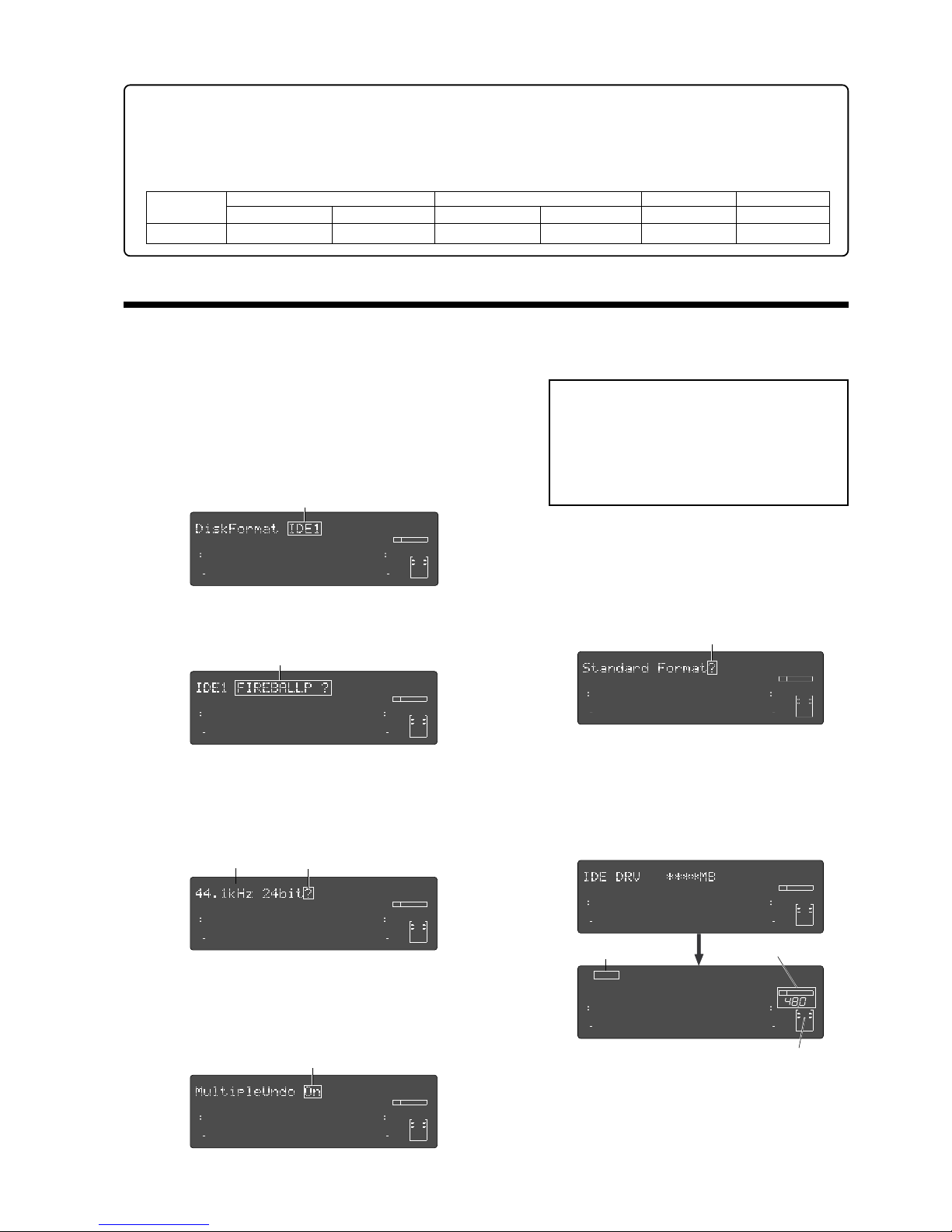
33
Model D2424LVmkII Reference Manual (Formatting and Optimizing Disks)
Capacity
10.0GB
44.1kHz 48kHz 96kHz
16 bits 24 bits
16 bits
24 bits
24 bits
Approx. 1888 min.
Approx. 1258 min.
Approx. 1735 min. Approx. 1156 min.
Approx. 577 min.
Formatting a brand new hard disk (Current drive)
This section describes how to format an E-IDE hard disk used for the current drive, assuming that a hard disk
has already been installed in the recorder. To format a CompactFlash
TM
card (or the optional E-IDE hard disk
drive), follow the procedure descrived in page 35.
(1) T urn on the power to the recorder.
The recorder displays the ROM version, time and
date, then displays “Initializing...”, “Current IDE
Drv”, “(model name of the hard disk)” in this order,
then “Unformat !” momentarily. Finally, the unit
displays the “Disk Format?” menu in Setup mode,
showing the following screen.
(2) Press the [EXECUTE/YES] key.
The model name of the current E-IDE hard disk and
“?” flash on the screen.
(3) Press the [EXECUTE/YES] key again.
The recorder displays the screen that enables you
to set the sampling frequency and bit resolution.
(With the default setting, “44.1kHz 24bit?” appears.)
Refer to the table on page 31 and turn the Jog dial
to select the desired setting.
(4) After you select the desired sampling frequency
and bit resolution using the Jog dial, press the
[EXECUTE/YES] key.
The recorder displays the screen which enables you
to set the Multiple Undo function on or off.
(5) After setting the multiple undo function on or off
using the Jog dial, press the [EXECUTE/YES] key.
The recorder displays the screen which enables you
to select the format type. With the default setting,
“Standard Format?” appears.
Be sure to select “Standard Format?” to format an
unformatted disk.
(6) Press and hold down the [RECORD] button and
press the [EXECUTE/YES] key.
The recorder starts formatting the disk, and displays
the size of the unformatted area on the target disk.
This value counts down as the formatting operation
proceeds. Wait until the format operation is
complete.
(7) After formatting is complete, press the [EXIT/NO]
key (or the [STOP] button).
<Availab le recor ding time after f ormatting>
A greater sampling frequency will reduce the available recording time/space after formatting. Under the same sampling frequency setting, the greater quantization (bit number) reduces the available recording time.
The following table shows the "approximate av ailab le recording time " under each sampling frequency/quantization.
Depending on your medium, the available recording time may differ slightly. It will be a good idea to check the
available recording time after formatting.
Flashing
Flashing
Flashing
Flashing
Flashing
88.2kHz
24 bits
Approx. 628 min.
∞
42
OL
0
30
24
18
12
9
6
3
kHz
24
FS
BIT
SETUP
∞
42
OL
0
30
24
18
12
9
6
3
232221201918
17
16151413121110
98765
4
3
2
1
CLOCK
Flashing
∞
42
OL
0
30
24
18
12
9
6
3
kHz
24
FS
BIT
SETUP
∞
42
OL
0
30
24
18
12
9
6
3
232221201918
17
16151413121110
98765
4
3
2
1
CLOCK
∞
42
OL
0
30
24
18
12
9
6
3
kHz
24
FS
BIT
SETUP
∞
42
OL
0
30
24
18
12
9
6
3
SURE?
232221201918
17
16151413121110
98765
4
3
2
1
CLOCK
∞
42
OL
0
30
24
18
12
9
6
3
kHz
24
FS
BIT
SETUP
∞
42
OL
0
30
24
18
12
9
6
3
232221201918
17
16151413121110
98765
4
3
2
1
CLOCK
∞
42
OL
0
30
24
18
12
9
6
3
kHz
24
FS
BIT
SETUP
∞
42
OL
0
30
24
18
12
9
6
3
232221201918
17
16151413121110
98765
4
3
2
1
CLOCK
∞
42
OL
0
30
24
18
12
9
6
3
kHz
24
FS
BIT
SETUP
∞
42
OL
0
30
24
18
12
9
6
3
REMAIN
232221201918
17
16151413121110
98765
4
3
2
1
CLOCK
∞
42
OL
0
30
24
18
12
9
6
3
kHz
24
FS
BIT
SETUP
24
∞
42
OL
0
30
24
18
12
9
6
3
COMPLETED!
232221201918
17
16151413121110
98765
4
3
2
1
CLOCK
INT
Lit
FS and bit resolution
Lit (“INT”)
<Note>:
It is recommended to enable the
multiple undo function. When it is enabled, you
can go back to the any previous take by
specifying the date and time when you made
the take (time jump function).
See page 69 for details about the multiple undo
function.
Page 34
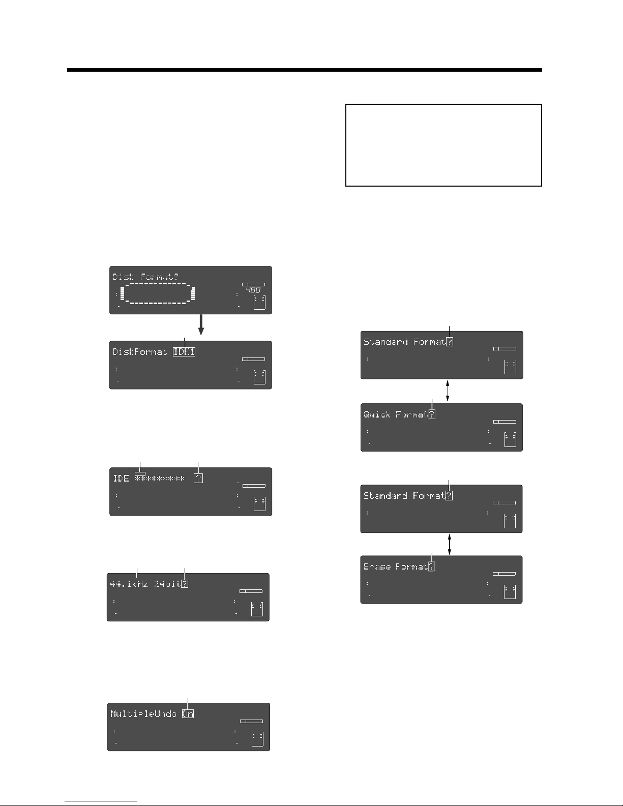
34
Model D2424LVmkII Reference Manual (Formatting and Optimizing Disks)
Re-Formatting the Current Drive
Follow procedures below to re-format the current drive.
(1) T urn on the power to the recorder.
The recorder starts with an indication of the
beginning (Timebase: ABS 0) of the program that
was selected before the power was turned off.
Even if a back-up E-IDE hard disk is installed, the
current drive starts up when the power is turned
on.
(2) Press the [SETUP] key to put the recorder into
Setup mode.
(3) Use the Jog dial to select “Disk Format ?” and
press the [EXECUTE/YES] key.
“IDE1” flashes in the same way mentioned in
“Formatting a new disk.”
(6) Select the desired sampling frequency and bit
resolution using the Jog dial, and press the
[EXECUTE/YES] key.
The recorder displays the screen which enables you
to set the Multiple Undo function on or off.
(4) Press the [EXECUTE/YES] key while “IDE1” is
flashing.
The model name of the current drive’s hard disk
appears and “SURE ?” flashes.
∞
42
OL
0
30
24
18
12
9
6
3
kHz
24
FS
BIT
SETUP
24
∞
42
OL
0
30
24
18
12
9
6
3
232221201918
17
16151413121110
98765
4
3
2
1
CLOCK
INT
∞
42
OL
0
30
24
18
12
9
6
3
kHz
24
FS
BIT
SETUP
∞
42
OL
0
30
24
18
12
9
6
3
SURE?
232221201918
17
16151413121110
98765
4
3
2
1
CLOCK
∞
42
OL
0
30
24
18
12
9
6
3
kHz
24
FS
BIT
SETUP
∞
42
OL
0
30
24
18
12
9
6
3
232221201918
17
16151413121110
98765
4
3
2
1
CLOCK
∞
42
OL
0
30
24
18
12
9
6
3
kHz
24
FS
BIT
SETUP
∞
42
OL
0
30
24
18
12
9
6
3
SURE?
232221201918
17
16151413121110
98765
4
3
2
1
CLOCK
(5) Press the [EXECUTE/YES] key.
The recorder displays the screen that enables you
to set the sampling frequency and bit resolution.
∞
42
OL
0
30
24
18
12
9
6
3
kHz
24
FS
BIT
SETUP
∞
42
OL
0
30
24
18
12
9
6
3
232221201918
17
16151413121110
98765
4
3
2
1
CLOCK
(7) Set the Multiple Undo function on or off using the
Jog dial, and press the [EXECUTE/YES] key.
The recorder displays the screen which enables you
to select the format type. If you have formatted the
disk with Standard Format, you can select either
Standard Format or Erase Format.
If you have formatted the disk with Quick Format,
you can select either Standard Format or Quick
Format.
Be sure to select “Standard Format?” to format a backup E-IDE hard disk.
∞
42
OL
0
30
24
18
12
9
6
3
kHz
24
FS
BIT
SETUP
∞
42
OL
0
30
24
18
12
9
6
3
232221201918
17
16151413121110
98765
4
3
2
1
CLOCK
∞
42
OL
0
30
24
18
12
9
6
3
kHz
24
FS
BIT
SETUP
∞
42
OL
0
30
24
18
12
9
6
3
232221201918
17
16151413121110
98765
4
3
2
1
CLOCK
∞
42
OL
0
30
24
18
12
9
6
3
kHz
24
FS
BIT
SETUP
∞
42
OL
0
30
24
18
12
9
6
3
232221201918
17
16151413121110
98765
4
3
2
1
CLOCK
∞
42
OL
0
30
24
18
12
9
6
3
kHz
24
FS
BIT
SETUP
∞
42
OL
0
30
24
18
12
9
6
3
232221201918
17
16151413121110
98765
4
3
2
1
CLOCK
(8) Use the Jog dial to select the desired format type,
then press and hold down the [RECORD] button
and press the [EXECUTE/YES] key.
The recorder starts formatting the disk.
(9) After formatting is complete, press the [EXIT/NO]
key (or the [STOP] button).
Flashing
Flashing
Flashing
Flashing Flashing
Flashing
Flashing
Flashing
Flashing
Flashing
or
<Note>:
It is recommended to enable the
multiple undo function. When it is enabled, you
can go back to the any previous take by
specifying the date and time when you made
the take (time jump function).
See page 69 for details about the multiple undo
function.
Page 35
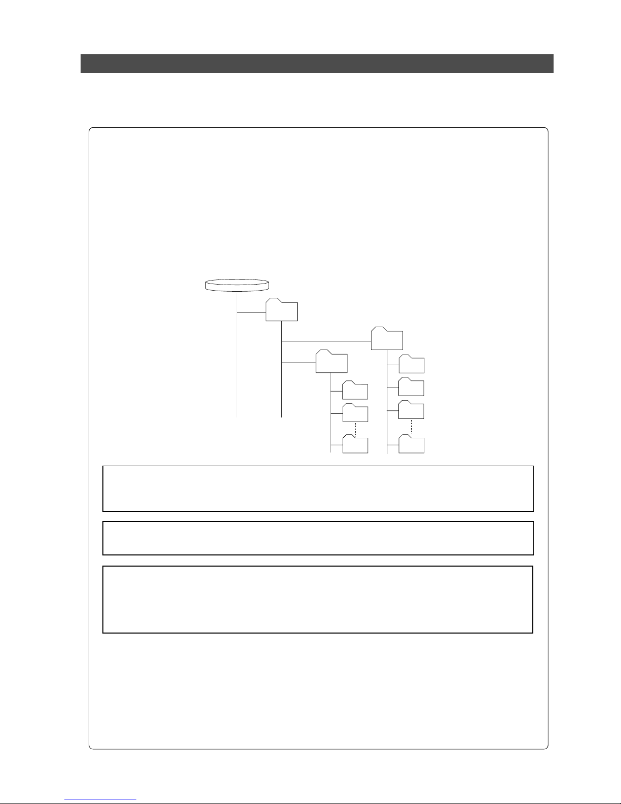
35
Model D2424LVmkII Reference Manual (Formatting and Optimizing Disks)
Formatting a backup medium (CompactFlashTM card or optional E-IDE hard disk drive)
You can format a backup medium (a CompactFlashTM card or optional E-IDE hard disk) in "24 bit backup" or
"16 bit backup" mode or in "DOS" format.
When a medium is DOS-formatted, FAT 16 or FAT 32 standard is automatically selected according to its
storage capacity (see the following for details about DOS formatting).
About FAT 32 format
When you use the D2424LVmkII to DOS-format a medium (CompactFlashTM card or optional E-IDE
hard disk) with the storage capacity between 530 MB and 320 GB, it is automatically formatted in
FAT 32 standard.
On the FAT 32 formatted medium, the "D2424LVmkII" folder is created in the root folder and some
folders are automatically created under the "D2424LVmkII" folder as shown below.
The WAV folder is used for storing WAV files, while the BACKUP folder is used for storing binary
data (DAT files) for backup of the FDMS-3 (Fostex Disk Management System-3). See page 94 for
details about saving/loading using a FAT 32 formatted medium.
<Note>:
The D2424LVmkII can use up to 320 GB disk space. Therefore, if you DOS-format a hard
disk drive of more than 320 GB capacity using the D2424LVmkII, you can use only 320 GB of the
disk space with the D2424LVmkII.
BACKUP DISK
(CF card or E-IDE HDD)
WAV
D2424W01
BACKUP
D2424W02
D2424B01
D2424B02
D2424B03
D2424Bnn
D2424Wnn
D2424LVmkII
About FAT 16 f ormat
When you use the D2424LVmkII to DOS-format a medium (CompactFlashTM card) with the capacity
between 128 MB and 529 MB, it is automatically formatted in FAT 16.
Unlike a FAT 32 formatted medium, no folder is created in the FAT 16 formatted medium. You can
only save or load WAV files. See page 98 for details about saving/loading using a FAT 16 formatted
medium.
<Note>:
When you format a hard disk drive with more than 320 GB (for example, 500 MB) using
the D2424LVmkII, the area which is not used by the D2424LVmkII can be used by a personal
computer for other purposes. However, by executing save or load operation from the D2424LVmkII,
data written by a computer may be destroyed. Therefore, we recommend not using the area
which is not used by the D2424LVmkII.
<Note>:
Do not write any data other than D2424LVmkII data to the area formatted by the
D2424LVmkII.
Page 36
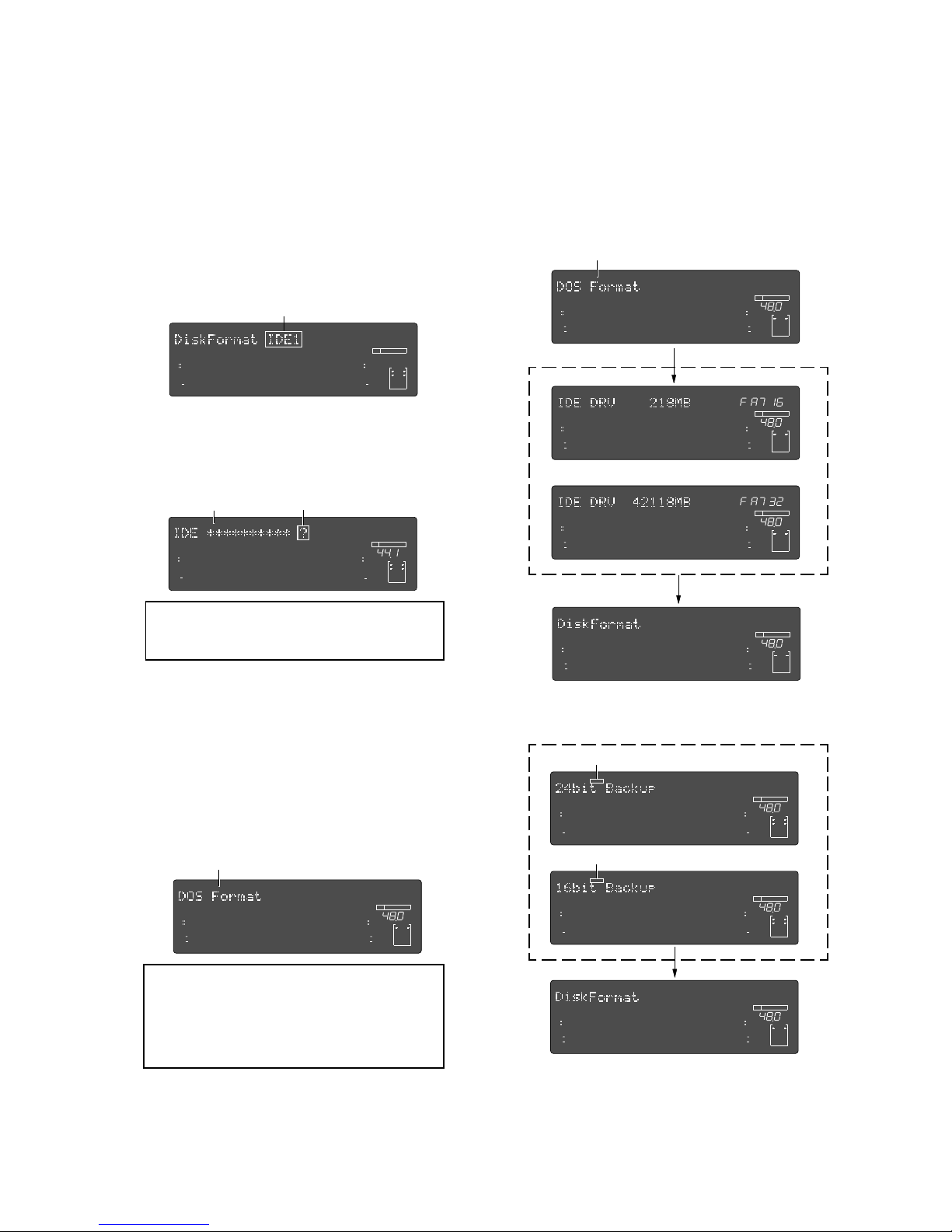
36
Model D2424LVmkII Reference Manual (Formatting and Optimizing Disks)
(3) Use the Jog dial to select flashing “IDE2” and press
the [EXECUTE/YES] key.
The display shows the name of the CompactFlash
TM
card currently set to the CF drive, as well as flashing
"?" and "SURE?".
(4) Press the [EXECUTE/YES] key again.
The display shows the backup format mode (by
default, "DOS Format").
You can select the backup format mode between
"DOS Format" and "24bit Backup" or "16bit Backup"
depending on the bit depth setting of the current
drive.
To enable WAV file saving/loading, select "DOS
Format". To enable FDMS-3 saving /loading, select
"24bit Backup" (or "16bit Backup").
(6) Press the [EXIT/NO] key (or the [STOP] button) to
exit Setup mode.
The recorder displays the time base value of the
current drive that was shown before the unit
entered Setup mode.
FlashingFlashing
Flashing
<Bit resolution>
The same figures in quantization of the current
drive will be displayed for quantization of the
backup format. Thus, when the current drive is
24bit, “
24bit Backup?
” will be displayed, and for
16bit, “
16bit Backup?
” will be displayed.
(1) Press the [SETUP] key to put the recorder into
Setup mode.
(2) Turn the Jog dial to select the “Disk Format?” menu
and press the [EXECUTE/YES] key.
“IDE1” flashes.
To format a CompactFlash
TM
card (or E-IDE hard
disk) for backup, you have to select "IDE2".
Flashing
∞
42
OL
0
30
24
18
12
9
6
3
kHz
24
FS
BIT
SETUP
∞
42
OL
0
30
24
18
12
9
6
3
232221201918
17
16151413121110
98765
4
3
2
1
CLOCK
∞
42
OL
0
30
24
18
12
9
6
3
DIGITAL
kHz
FS
CLOCK
BIT
SETUP
INT
16
1
24
∞
42
OL
0
30
24
18
12
9
6
3
SURE?
234
5
6
78
91011 12 131415 16
17
1819202122 23
24
42
OL
0
30
24
18
12
9
6
3
kHz
24
FS
BIT
SETUP
24
42
OL
0
30
24
18
12
9
6
3
SURE?
232221201918
17
16151413121110
98765
4
3
2
1
CLOCK
INT
42
OL
0
30
24
18
12
9
6
3
kHz
24
FS
BIT
SETUP
24
42
OL
0
30
24
18
12
9
6
3
SURE?
232221201918
17
16151413121110
98765
4
3
2
1
CLOCK
INT
42
OL
0
30
24
18
12
9
6
3
kHz
24
FS
BIT
SETUP
24
42
OL
0
30
24
18
12
9
6
3
REMAIN
232221201918
17
16151413121110
98765
4
3
2
1
CLOCK
INT
42
OL
0
30
24
18
12
9
6
3
kHz
24
FS
BIT
SETUP
24
42
OL
0
30
24
18
12
9
6
3
REMAIN
232221201918
17
16151413121110
98765
4
3
2
1
CLOCK
INT
42
OL
0
30
24
18
12
9
6
3
kHz
24
FS
BIT
SETUP
24
42
OL
0
30
24
18
12
9
6
3
232221201918
17
16151413121110
98765
4
3
2
1
CLOCK
INT
COMPLETED!
∞
42
OL
0
30
24
18
12
9
6
3
kHz
24
FS
BIT
SETUP
24
∞
42
OL
0
30
24
18
12
9
6
3
SURE?
232221201918
17
16151413121110
98765
4
3
2
1
CLOCK
INT
∞
42
OL
0
30
24
18
12
9
6
3
kHz
24
FS
BIT
SETUP
24
∞
42
OL
0
30
24
18
12
9
6
3
SURE?
232221201918
17
16151413121110
98765
4
3
2
1
CLOCK
INT
42
OL
0
30
24
18
12
9
6
3
kHz
24
FS
BIT
SETUP
24
42
OL
0
30
24
18
12
9
6
3
232221201918
17
16151413121110
98765
4
3
2
1
CLOCK
INT
COMPLETED!
The following procedure shows how to format a CompactFlashTM card for backup. You can format an E-IDE
hard disk instead of a CompactFlash
TM
card in the similar manner. For details about save/load operation using
a CompactFlash
TM
card or E-IDE hard disk, see page 96.
<Note>:
When an E-IDE hard disk is set as a
backup medium, the name of the hard disk
drive is shown.
(5) Use the jog dial to select the format mode, and
press the [EXECUTE/YES] key while holding down
the [RECORD] key.
<When selecting "DOS Format">
The unit starts formatting in "FAT16" or "FAT32"
depending on the capacity of the medium. When
formatting is completed, the display shows
"COMPLETED!".
<When selecting "24bit Backup" or "16bit Backup">
The unit starts formatting. When formatting is
completed, the display shows "COMPLETED!".
or
or
Flashing
Flashing Flashing
Flashing
Flashing
Flashing
Page 37
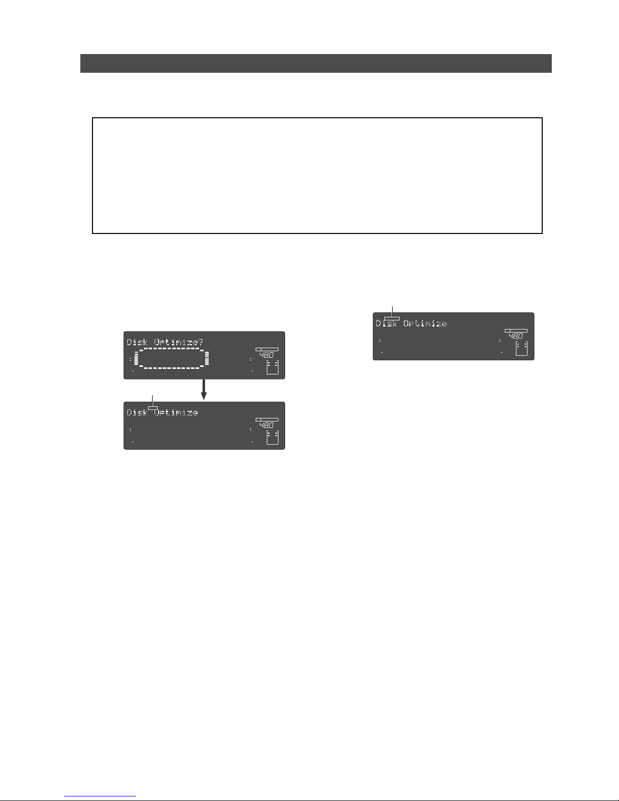
37
Model D2424LVmkII Reference Manual (Formatting and Optimizing Disks)
Optimizing the disk
If you are using a disk that was formatted with the Multiple Undo function turned on, free disk space becomes
smaller quickly because the disk always keeps the Multiple Undo files. Optimizing such a disk (using the “Disk
Optimize?” menu in Setup mode) will increase free block space.
<Notes>
• After you record multiple takes, if you optimize the disk (with the Multiple Undo function turned on), you will
be able to undo only the most recent take. Therefore, if you wish to keep some takes, perform the Multiple Undo
function or use the Program duplicate function to restore the take, then optimize the disk. For more information,
see “
Multiple Undo Function
” on page 69.
• After executing a format conversion via the “
Additional track format con ver sion
” menu in the SETUP mode, the
recorder will automatically enter the “
Disk Optimize?
” menu.
Therefore, we recommended that you optimize the disk immediately after format conversion. By optimizing,
the multiple undo history of tracks 25-56 will be erased and disk memory space may increase. For details on
additional track format conversion, refer to page “
127
.”
(1) While the disk is not being accessed, press the
[SETUP] key to put the unit into Setup mode.
(2) T urn the Jog dial to select the “Disk Optimize?”
menu and press the [EXECUTE/YES] key.
The recorder displays the following indication and
“SURE ?” flashes.
(3) Press and hold down the [RECORD] button and
press the [EXECUTE/YES] key.
The disk optimize function starts.
When it is complete, “COMPLETED!” lights up.
(4) Press the [EXIT/NO] key (or [STOP] b utton) to e xit
Setup mode.
Flashing
∞
42
OL
0
30
24
18
12
9
6
3
kHz
24
FS
BIT
SETUP
24
∞
42
OL
0
30
24
18
12
9
6
3
232221201918
17
16151413121110
98765
4
3
2
1
CLOCK
INT
∞
42
OL
0
30
24
18
12
9
6
3
kHz
24
FS
BIT
SETUP
24
∞
42
OL
0
30
24
18
12
9
6
3
232221201918
17
16151413121110
98765
4
3
2
1
CLOCK
INT
SURE?
∞
42
OL
0
30
24
18
12
9
6
3
kHz
24
FS
BIT
SETUP
24
∞
42
OL
0
30
24
18
12
9
6
3
232221201918
17
16151413121110
98765
4
3
2
1
CLOCK
INT
COMPLETED!
Lit
Page 38
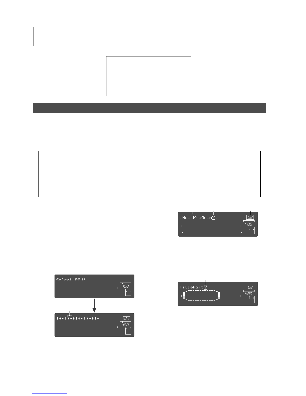
38
Model D2424LVmkII Reference Manual (Handling Programs)
Handling Programs
This chapter explains how to handle Programs. It covers the following topics:
1. Creating a new Pr ogram
2. Using a Program Change function
3. Duplicating a Program
4. Deleting a Program
5. Editing a Program title
6. Changing the program FS
Creating a new Program
You can manage individual songs by setting multiple programs on the disk, as explained in the
“Managing Songs by Program Selection” section of the “Before Starting” chapter. You can set up to
99 Programs. One Program is automatically created on the disk when the disk is newly formatted
with this equipment. Follow the steps below to create a new Program. The prerequisite of this
operation is that the disk is in an “initial state” where there is only one Program on the disk.
<Note>
• When a new program is made, the same initial setup of the currently active program will be copied as the initial
setting for the new program. If you wish to make a new program under the same settings as those of a previous
program, call up the desired program to be copied before making the new program.
• A new compilation is possible only when the "
Chain Play?
" (Setup of the chain play mode) menu in the SETUP
mode is set to "Off." If the
[PGM SEL]
key is pressed when the "
Chain Play?
" menu is set in other than the "
Off
"
mode, the D2424LVmkII will enter the "
Chain play mode
." Before starting compilation, check that the "
Chain
Play?
" is "
Off
" and if it is not, be sure to reset it to "
Off
."
(1) Turn on the power to the recor der.
Upon starting up the recorder, “Initialize...”->
“Current IDE Drv” -> “Hard disk model number”->
“Storage mode (“Standard format” in this case)
messages are followed with an ABS time base, then
show the top of the Program (ABS 0).
At this time, the current Program is indicated as
“P01”.
(2) Press the [PGM SEL] key.
“Select PGM!” appears on the display briefly, then
changes to a flashing “01” and “SURE?” flash.
(“******” is the name of PGM 01.)
(3) T urn the Jog dial clockwise.
The question marks “?” of “[New Program?]” and
“SURE?” flash. This indication asks you if you wish
to set a new Program (Program 2).
(4) Press the [EXECUTE/YES] key.
The recorder automatically enters “Title Edit PGM?”
menu in SETUP mode.
You can enter a title for Program 2. (“?” flash.)
If you prefer the default name, press the [EXIT/NO]
key.
(5) Press the [EXECUTE/YES] key again.
A default title (#0002) appears on the display, with
“#” and “SURE?” flashing.
This means that you can enter a name for the new
Program.
If you wish to name the Program with a unique title,
continue the steps below.
In either case, you can change the title later, as
explained in “Editing a Program title.”
Flashing
Flashing
Flashing
∞
42
OL
0
30
24
18
12
9
6
3
kHz
24
FS
BIT
24
∞
42
OL
0
30
24
18
12
9
6
3
232221201918
17
16151413121110
98765
4
3
2
1
CLOCK
INT
∞
42
OL
0
30
24
18
12
9
6
3
kHz
24
FS
BIT
PGM
24
∞
42
OL
0
30
24
18
12
9
6
3
SURE?
232221201918
17
16151413121110
98765
4
3
2
1
CLOCK
INT
Flashing
Flashing
∞
42
OL
0
30
24
18
12
9
6
3
kHz
24
FS
BIT
PGM
24
∞
42
OL
0
30
24
18
12
9
6
3
SURE?
232221201918
17
16151413121110
98765
4
3
2
1
CLOCK
INT
Flashing
∞
42
OL
0
30
24
18
12
9
6
3
kHz
24
FS
BIT
SETUP
24
∞
42
OL
0
30
24
18
12
9
6
3
232221201918
17
16151413121110
98765
4
3
2
1
CLOCK
INT
PGM
Page 39
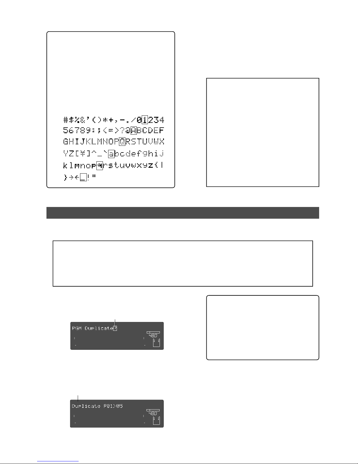
39
Model D2424LVmkII Reference Manual (Handling Programs)
Duplicating a Program
<Notes>
* Duplicating a program is possible only when the Multiple Undo function is set to ON when formatting the
current drive. In a current drive with this setting at OFF, the “
PGM Duplicate?
” message will not display when
pressing the
[EDIT]
key mentioned below.
* The program which can be duplicated must be the currently active program.
Therefore, the program you wish to duplicate must be activated prior to executing the duplicating mode.
T o enter a title:
• T urn the Jog dial, or pressing the [NEXT] key and
[PREV] key for the flashing cursor to v oluntarily input
alphanumerics.
Press the [PREV] key/[NEXT] key and the recorder will
jump to the letters/symbols listed below (small square
position).
• Move the flashing cursor with the Shuttle dial.
• Y ou can input the f ollowing alphanumerics and
symbols.
Titles can contain up to 16 alphanumeric characters.
(6) When you finish entering the title, press the
[EXECUTE/YES] key.
Program 2 (PGM 02) and its title are set.
The display shows the ABS Time Base indication of
the Program.
(7) Press the [EXIT/NO] key, or [STOP] button.
<Important!>
• When you create a new Program by
selecting the “
New PGM ?
” menu, a new
Program is created with an increment
number.
That is, if only one Program exists and when
you create a new Program, it will be named
Program 2. If Programs 1-5 already exist, a
new Program number will be 6.
• Remember that producing new programs
gradually decreases recordable disk space.
If disk space is insufficient, or if 99
programs have already been created, you
cannot create more new programs.
If a new program is attempted, “
Can’t New
PGM!
” will indicate that the operation is
invalid.
Any program content (Recording data/various setup items) can be duplicated but with a separate
program number.
(1) With this recorder in the stop mode, press the
[EDIT] key to display “PGM Duplicate?” (“?”
flashes).
(2) Press the [EXECUTE/YES] key.
As an example, the following is displayed and
“SURE?” will flash. This means that program 01
will be duplicated for program 05, the new program
05. Refer see <Note> below.
<Note>:
The program to be duplicated will be
assigned with a program number following that
of the program presently existing in the disk.
If “
Duplicate P01 > 05
” is displayed as in the
previous example, this indicates that four
programs presently exist in the disk and that
the new program will be number 05.
If the duplicated program is to be checked or
you wish to switch to this program, refer to the
next item “
Selecting a program
.”
(3) Press the [EXECUTE/YES] key again.
The display will change to head of the duplicated
original program (P01 in this example), and
“COMPLETED!” will light.
(4) Press the [EXIT/NO] key (or [STOP] button).
“COMPLETED!” will be extinguished.
By following these procedures, the same content in
program 01 is duplicated in program 05.
Flashing
Flashing
∞
42
OL
0
30
24
18
12
9
6
3
kHz
24
FS
BIT
24
∞
42
OL
0
30
24
18
12
9
6
3
232221201918
17
16151413121110
98765
4
3
2
1
CLOCK
INT
∞
42
OL
0
30
24
18
12
9
6
3
kHz
24
FS
BIT
24
∞
42
OL
0
30
24
18
12
9
6
3
SURE?
232221201918
17
16151413121110
98765
4
3
2
1
CLOCK
INT
Page 40
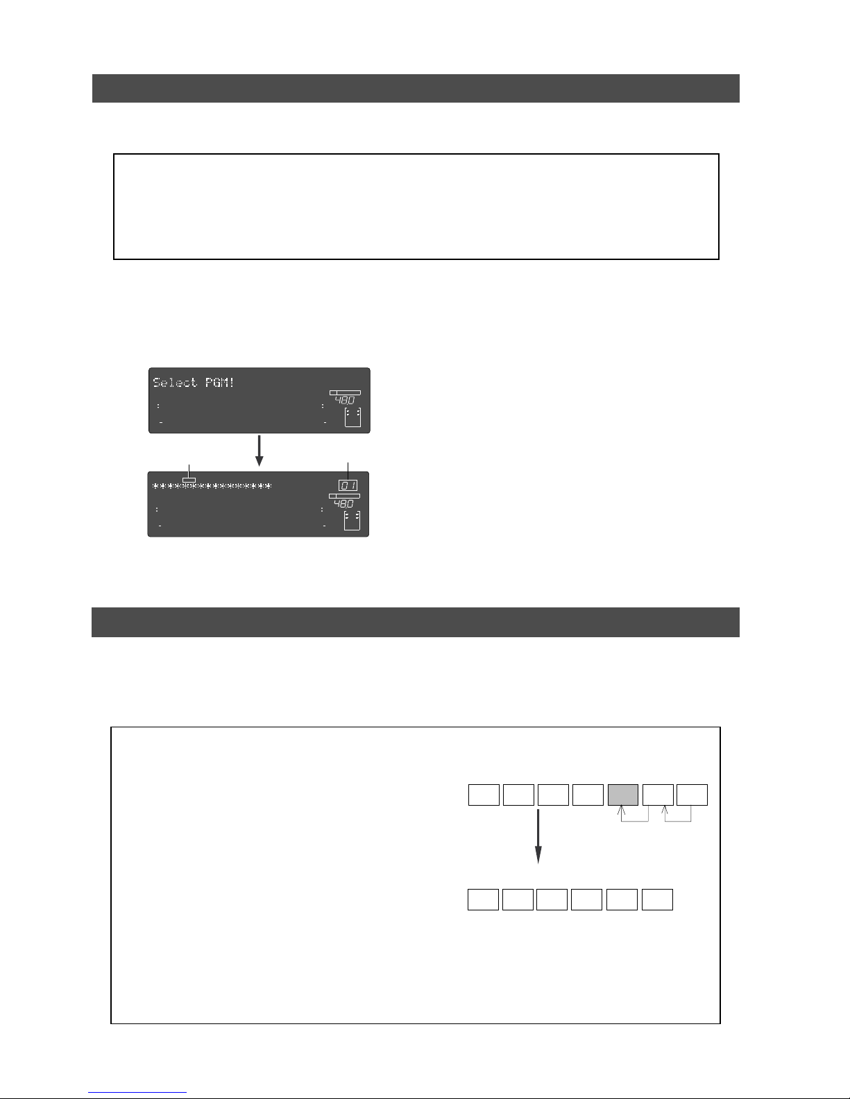
40
Model D2424LVmkII Reference Manual (Handling Programs)
P01
P02 P03
P04 P05
P06
P07
P01
P02 P03 P04
P05
P06
If you try to deleted PGM 05, only the
data of PGM 05 will be deleted and the
data of PGM 06 will move into PGM 05.
After deleted
Using a Program Change function
If multiple Programs exist on the disk, you need to select a Program to record, play, or edit.
This section describes how to select a Program.
<Notes>
• You cannot use the Program Change function when the recorder is in SETUP mode.
• The program change is possible only when the “
Chain Play?
” (Setup of the chain play mode) menu in the
SETUP mode is set to “
Off
.” If the
[PGM SEL]
key is pressed when the “
Chain Play?
” menu is set in other than
the “
Off
” mode, the recorder will enter the “
Chain Play mode
.” Before starting program change, check that
the “
Chain Play?
” menu is “
Off
” and if it is not, be sure to reset it to “
Off
.”
(1) When the recorder is stopped, press the [PGM SEL]
key .
“Select PGM!” appears on the display briefly, then
changes to a flashing “01” and “SURE?”. (“****” is
the name of PGM 01.)
(2) Turn the Jog dial to select the desired Program
number (flashing).
Rotating the Jog dial counter-clockwise decreases
the number, and rotating it clockwise increases the
number.
If you turn the Jog dial clockwise all the way, “New
Program?” will be selected. Select “New Program ?”
to create a new Program as mentioned in the
previous section “Creating a new Program.”
(3) Press the [EXECUTE/YES] key.
The ABS Time Base indication for the selected
Program appears.
In this way, you can be sure to select a Program
before you start working.
Deleting a Program
This section explains how to delete an unnecessary Program.
Deleting an unnecessary Program will expand the recordable area, making your work flow more
smoothly, since recording or editing requires sufficient recordable area (free space on the disk).
Use the “Delete PGM ?” menu in SETUP mode to delete a Program.
<Notes on deleting a Program>
• You can delete only the currently-selected Program. Refer to
the previous section, “Using a Program Change function,” for
information on how to select the desired Program before you
proceed to delete the Program.
• If only one Program exists and you try to delete it, data
contained in the Program will be deleted, but the Program
itself will remain.
For example, assume that PGM 01 -07 exist and you try to
delete PGM 05. Program number 05 will remain, but the data
inside PGM 05 will be replaced with the data of PGM 06.
The subsequent Programs’ data will move in the same way.
Therefore, it will appear that PGM 07 has been deleted.
If you delete the last Program (PGM 07 in this example), PGM
07 will be completely deleted.
If you try to deleted PGM 05, only the data of PGM 05 will be
deleted and the data of PGM 06 will move into PGM 05.
<Note>:
You cannot use the Single Undo/Redo function, and Multiple Undo function to delete Programs.
Make sure that you delete the correct Program.
Flashing
∞
42
OL
0
30
24
18
12
9
6
3
kHz
24
FS
BIT
24
∞
42
OL
0
30
24
18
12
9
6
3
232221201918
17
16151413121110
98765
4
3
2
1
CLOCK
INT
∞
42
OL
0
30
24
18
12
9
6
3
kHz
24
FS
BIT
PGM
24
∞
42
OL
0
30
24
18
12
9
6
3
SURE?
232221201918
17
16151413121110
98765
4
3
2
1
CLOCK
INT
Flashing
Page 41
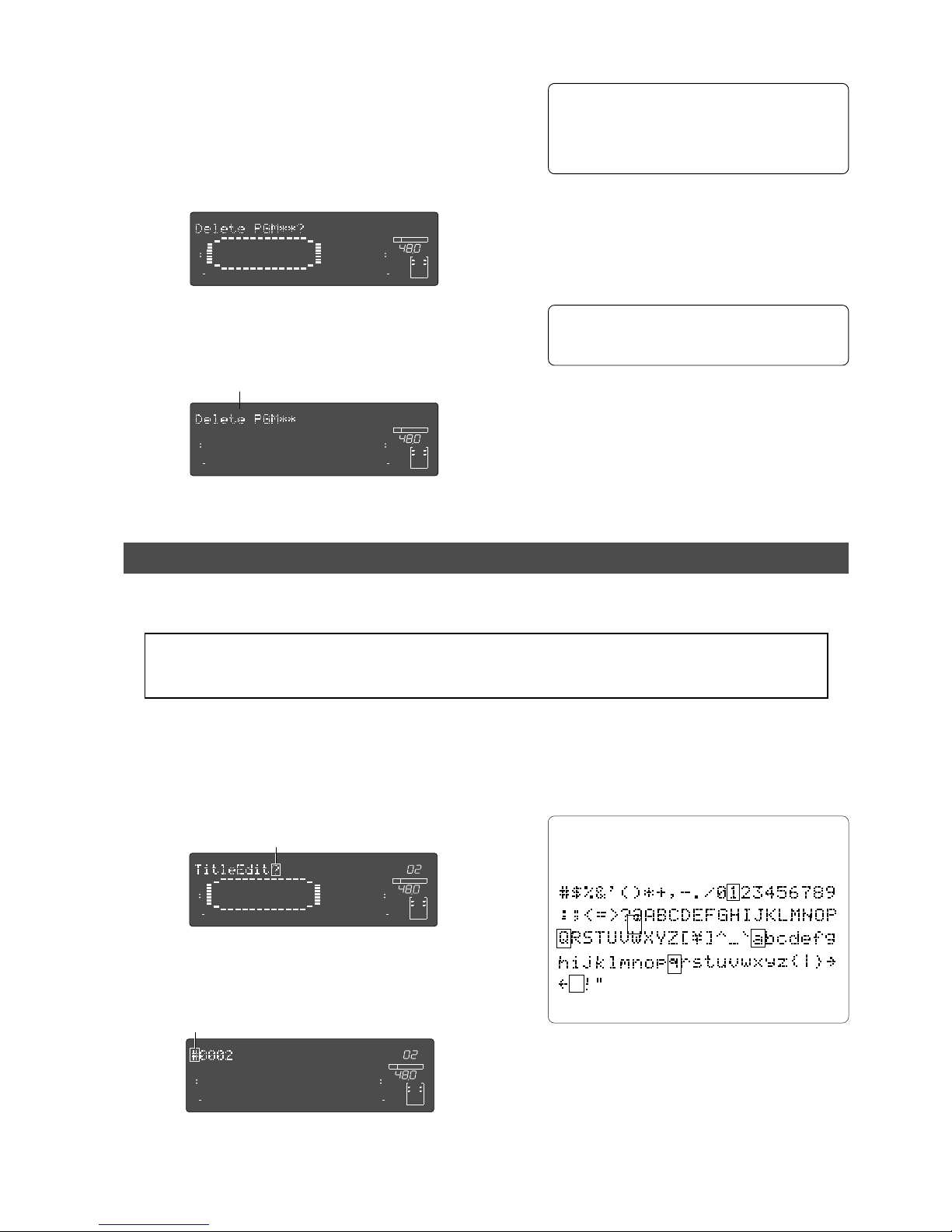
41
Model D2424LVmkII Reference Manual (Handling Programs)
(1) Press the [SETUP] key while the recorder is
stopped, to put the system in the SETUP mode.
(2) Turn the Jog dial to select the first hierarchy of the
“Delete PGM ** ?” (deleting a Pr ogram) men u.
Alternatively, you can use the Shuttle dial, [REV]
key, or [NEXT] key.
(3) Press the [EXECUTE/YES] key.
The display will change and “SURE?” will flash?
This indicates that the system is in the stand-by
state to delete a program that is currently started
up.
To cancel the delete operation, press the
[EXIT/
NO]
key while “
SURE?
” is flashing. Each time you
press the button or key, the recorder will return
to a higher level in the hierarchy, and finally
exit SETUP mode.
(4) Press the [EXECUTE/YES] key again.
When the recorder displays “Deleting...” and finishes
deleting the Program, the data of the next Program
number moves in, and its ABS time appears.
(5) Press the [EXIT/NO] key, or [STOP] button.
To check the REMAIN time and free space, press
the
[DISP SEL]
key to display the “REMAIN”
indication after the Program is deleted.
Editing a Program title
You can name the Program as explained in the “Creating a new Program” section.
You can also change the title later by using the “Title Edit ?” menu in SETUP mode.
<Note>:
You can edit the title of the selected Program before you select SETUP mode. You cannot select a
Program after the recorder enters SETUP mode. Be sure to select the desired Program using the steps explained
in the “
Using the Program Change function
” section.
(1) Press the [SETUP] key while the recorder is
stopped, to put the system in the SETUP mode.
(2) Turn the Jog dial to select the first hierarchy level
of the “Title Edit ?” (“?” flash.) menu.
Flashing
Flashing
Flashing
∞
42
OL
0
30
24
18
12
9
6
3
kHz
24
FS
BIT
SETUP
24
∞
42
OL
0
30
24
18
12
9
6
3
232221201918
17
16151413121110
98765
4
3
2
1
CLOCK
INT
∞
42
OL
0
30
24
18
12
9
6
3
kHz
24
FS
BIT
SETUP
24
∞
42
OL
0
30
24
18
12
9
6
3
232221201918
17
16151413121110
98765
4
3
2
1
CLOCK
INT
SURE?
(3) Press the [EXECUTE/YES] key.
The currently-selected Program title appears with
the left-most character flashing.
(4) Move the flashing cursor with the Shuttle dial and
input the letter or number with the Jog dial / [NEXT]
key / [PREV] key.
Up to 16 digits and the following letters / numbers
/ symbols can be input.
(5) After you enter the title, press the [EXECUTE/YES]
key .
The new title is confirmed, and the ABS time value
of the Program appears.
(6) Press the [EXIT/NO] key, or the [STOP] button.
∞
42
OL
0
30
24
18
12
9
6
3
kHz
24
FS
BIT
SETUP
PGM
24
∞
42
OL
0
30
24
18
12
9
6
3
232221201918
17
16151413121110
98765
4
3
2
1
CLOCK
INT
∞
42
OL
0
30
24
18
12
9
6
3
kHz
24
FS
BIT
SETUP
24
∞
42
OL
0
30
24
18
12
9
6
3
232221201918
17
16151413121110
98765
4
3
2
1
CLOCK
INT
PGM
Press the [PREV] key/[NEXT] key and the recorder
will jump to the letters/symbols listed below
(small square position).
Page 42
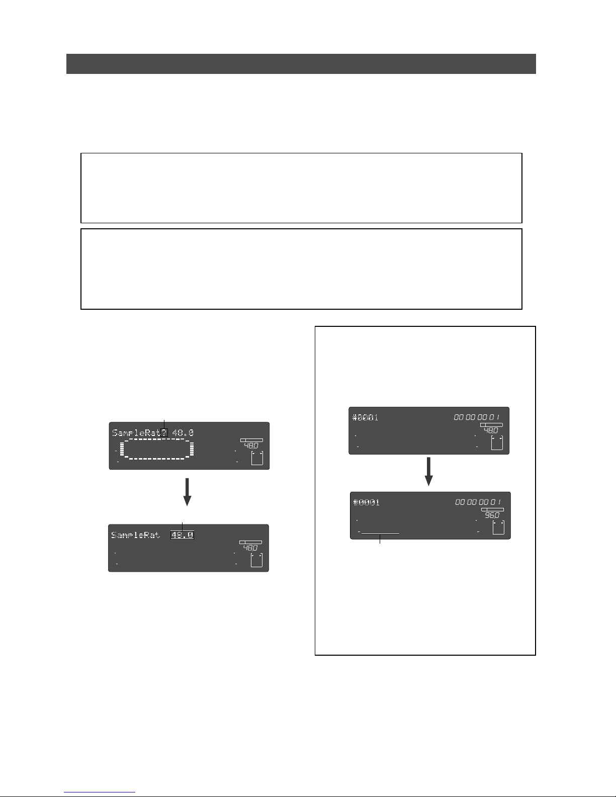
42
Model D2424LVmkII Reference Manual (Handling Programs)
Changing the program FS
Normally, when a new program is produced on the disk, this program will be made using the same
sampling frequency and quantization figures set when the disk was last formatted.
As explained in the separate sheet “Quick Operation Guide,” the recorder’s FS can be changed
subsequent to producing the program, so that it will be suitable for the application.
However, the changing the FS will be limited by the quantization figure used at formatting.
<Note: There is a limit to FS’ s whic h can be changed!>
The following FS is limited, depending on the quantization figure (16 bit or 24 bit) set when formatting the
current drive.
* 16 bit current drive -> 44.1kHz or 48kHz
* 24 bit current drive -> 44.1kHz, 48kHz, 88.2kHz or 96kHz
<Notes>
• FS can converted only in the program that is currently active. Do not change the FS of a program that has
been finished. Prerecorded data cannot be guaranteed.
• Do not copy & paste track data between programs with different FS.
Fostex does not guarantee song data which is created using the copy & paste function between programs with
different FS.
(1) Press the [SETUP] key while the recorder is
stopped, to put the system in the SETUP mode.
(2) T urn the Jog dial to select the first hierarchy level
of the “Sample Rate?” (“?” flash.) men u, and then
press the [EXECUTE/YES] key.
The currently-set FS will flash.
(3) Select the desired FS via the Jog dial and press
the [EXECUTE/YES] key.
Either 44.1 or 48 can be selected in a 16 bit program
and any one of 44.1/48/88.2/96 can be selected
for a 24 bit program.
Pressing the [EXECUTE/YES] key will set the selected
FS and change the display to the “Sample Rate?”
menu.
(4) Press the [EXIT/NO] key, or the [STOP] button.
The recorder will change to the head (ABS 0) of the
Normal display.
<Note>:
If you change the FS (44.1 or 48kHz) of a
program in the 24-track mode to 88.2 or 96kHz, the
program automatically changes to the 8-track mode
and track numbers 1 through 8 on the display are lit.
The following shows display examples when changing
the FS of a 48-kHz/24-bit program to 96kHz.
Also, note that if you change a program recorded in
the 24-track mode to an FS of the 8-track mode, tracks
1 through 8 can be used as real tracks, however, tracks
9 through 24 are data for additional tracks.
In other words, you cannot playback song data on track
9 through 24 in realtime.
To playback tracks 9 through 24, use the track exchange
function to move data to real tracks.
∞
42
OL
0
30
24
18
12
9
6
3
kHz
24
FS
BIT
SETUP
24
∞
42
OL
0
30
24
18
12
9
6
3
232221201918
17
16151413121110
98765
4
3
2
1
CLOCK
INT
∞
42
OL
0
30
24
18
12
9
6
3
kHz
24
FS
BIT
SETUP
24
∞
42
OL
0
30
24
18
12
9
6
3
232221201918
17
16151413121110
98765
4
3
2
1
CLOCK
INT
FSM
∞
42
OL
0
30
24
18
12
9
6
3
kHz
24
FS
BIT
PGM
24
∞
42
OL
0
30
24
18
12
9
6
3
ABS
232221201918
17
16151413121110
98765
4
3
2
1
CLOCK
INT
FSM
∞
42
OL
0
30
24
18
12
9
6
3
kHz
FS
BIT
PGM
24
∞
42
OL
0
30
24
18
12
9
6
3
ABS
8765
4
3
2
1
CLOCK
INT
Flashing
Flashing
Track n umbers 1 through 8 are effective.
Page 43
43
Model D2424LVmkII Reference Manual (Punch In/Out)
Punch In/Out
What is Punch In/Out recording?
Punch In/Out recording enables you to record over previously-recorded parts. See the diagram
below. For example, using the Punch In/Out function allows you to change an unsatisfactory guitar
solo. The D2424LVmkII offers two types of Punch In/Out functions. One is called Auto Punch In/Out,
in which you automatically re-record a specified part.
The other is called Manual Punch In/Out, in which you record data manually (using your foot to
operate an optional foot switch, model 8051). Both functions feature “Rehearsal mode” to enable
you to practice repeatedly until you are ready.
• Select a Program for Punch In/Out recording.
• Initialize the recorder.
• Check a sampling frequency of the recorder and external device.
<Notes>
• You can use the Punch In/Out recording only for Real tracks. If you wish to use Punch In/Out
recording for data on an Additional track, first move the data to the Real tracks.
• Before doing punch in/out, check that the SETUP mode “
Chain Play?
” menu is “
Off.
” If it is set
in other than “
Off
,” chain play will be executed.
Auto Punch In/Out
To perform Auto Punch In/Out recording, you need to specify the Auto Punch In point (recording
start point) and the Auto Punch Out point (recording end point).
Preparation
Storing the edit points
(1) Refer to “Storing the edit points” to set the Auto
Punch In/Out points.
Store the Auto Punch In point to the [AUT O PUNCH
IN] key, and the Auto Punch Out point to the [AUTO
PUNCH OUT] key.
• Refer to page “54” for more information on
storing the edit points.
<Note>:
Make sure that you specify an Auto
Punch In point that precedes the Auto Punch
Out point. If the Auto Punch Out point precedes
the Auto Punch In point, “
V oid Out!
” appears and
you will be unable to perform Auto Punch In/
Out recording.
Previewing and trimming the edit points
You can check the stored edit points by pressing the
corresponding memory keys to display them on the
LCD. You can also change the points if necessary.
In this example, use the Preview function to finetune the point while previewing.
(1) While the recorder is stopped, hold do wn the
[SHIFT] key and press the memory key.
Pressing the [AUTO PUNCH IN] key enables you to
listen to the sound at the AUTO PUNCH IN point
(“previewing the sound rise [fade-out]”).
Pressing the [AUT O PUNCH OUT] key enables you to
listen to the sound at the AUTO PUNCH OUT point
(“previewing the sound fall [fade-in]”).
(2) T rim the edit point while auditioning the sound.
• Refer to page “67” for more information on
the Preview function.
Page 44
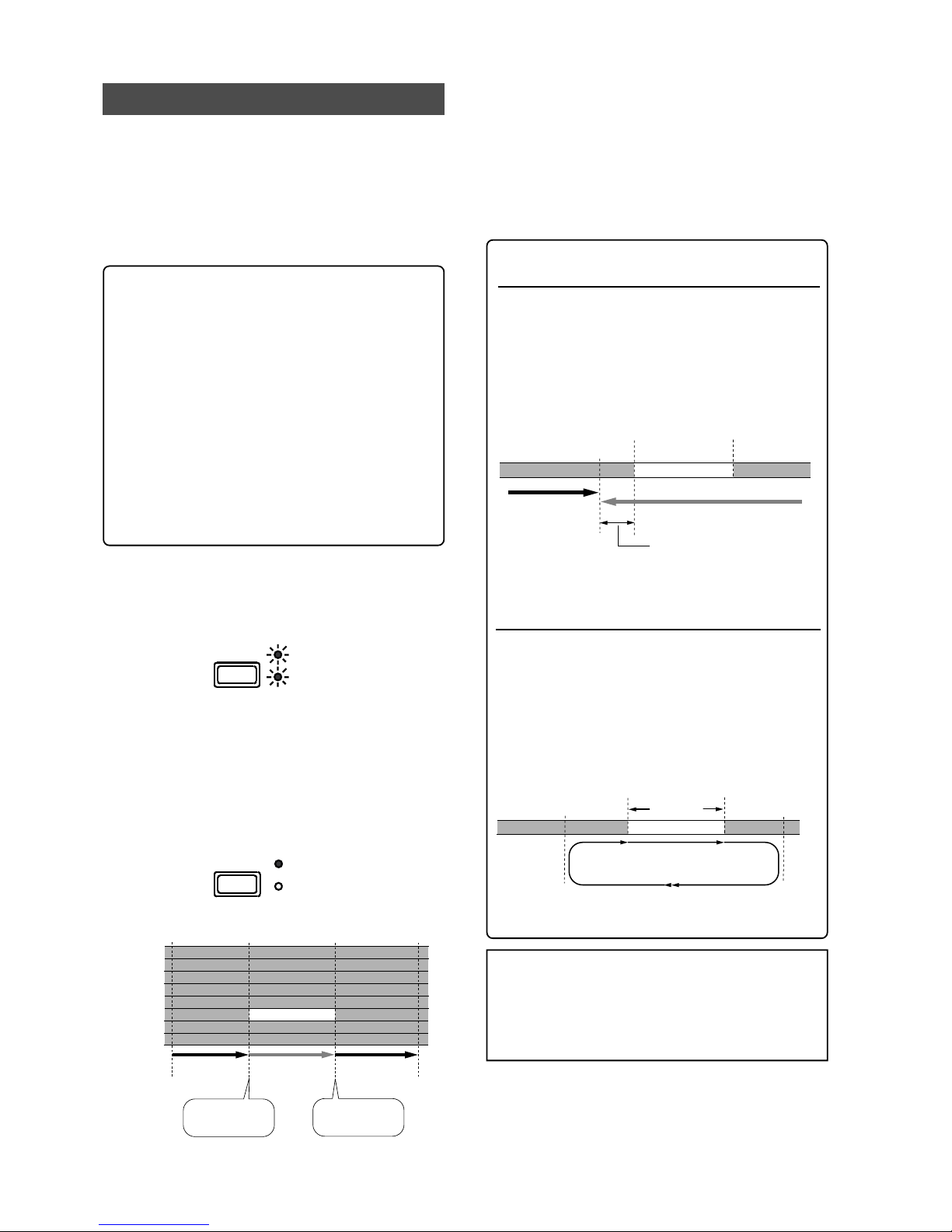
44
Model D2424LVmkII Reference Manual (Punch In/Out)
Rehearsing Auto Punch In/Out recor ding
In Rehearsal mode, the READY track assumes
input monitoring mode between the Auto
Punch In and Out points, and the sound is not
recorded. You can practice Auto Punch In/Out
operation repeatedly before you proceed to
actual recording. Locate the recording start
position slightly before the Auto Punch In point.
<Tips for rehearsal>
Set the preroll value while referring to the
“Changing the Initial Settings (SETUP Mode)”
chapter. In this way, the recorder can locate a
point that precedes the Auto Punch In point by
the specified preroll value. This enables you to
start playback slightly before the Punch In point.
(Refer to page “108” for more information on
“Changing the Initial Settings.”)
The recorder will repeat playback data between
the AUTO RTN START point and the AUTO RTN
END point if you set the AUTO RTN START point
before the Auto Punch In point and the AUTO
RTN END point after the Auto Punch Out point.
This allows you to repeat rehearsal. See the “Hint-
2.”.
(1) Press the [AUTO PUNCH] key.
The AUTO PUNCH mode will turn ON.
The REHEARSAL LED (green) and TAKE LED (red)
of the [AUT O PUNCH] key will flash.
(2) Set the track for Auto Punc h In/Out to READY.
Press the [RECORD TRACK] select key [3/11/19] to set
track 3 to READY.
(3) Start playback of the recorder from a point slightl y
before the Auto Punch In point.
Only the REHEARSAL LED (green) will light up, and
start rehearsal. The recorder operates as shown in
the figure below during rehearsal operations.
(4) Play the guitar accompanying the playbac k sound
from tracks 1 - 8 for rehear sal, while adjusting the
recording level.
You will hear the guitar performance between the
Auto Punch In and Out points. Otherwise, you will
hear the recorded guitar sound.
(5) When you are satisfied with your rehear sal, press
the [STOP] button.
<Hint 1>
Locating a point slightly before the A uto Punch In point
To locate the playback start point for rehearsal, press
the [AUT O PUNCH IN] key, then press the [LOCATE] key.
The recorder displays the time (position) stored in the
[AUT O PUNCH IN] key, and locates the point and stops.
Press the [REWIND] button to go backward. If you have
set the preroll time as described on page “113,” you
can locate a point that precedes the Auto Punch In point
by the specified preroll value.
<Hint 2>
Quick and easy operation for repeated rehearsal
Using the Auto Return function and the Auto Play
function enables you to rehearse repeatedly.
As shown below, set the AUTO RTN START and END
points for Auto Return and Auto Play. In this way, you
can repeat rehearsal easily, while checking the recording
level and concentrating on your performance.
Refer to page “54” for more information on setting the
AUTO RTN START/END points.
<Note>:
If the recorder displays
“Over!”
when you turn
on the Auto Punch mode, the disk does not have enough
free space to perform Auto Punch In/Out.
In such a case, erase any unnecessary sections, delete
unnecessary program data or optimize the disk and
execute again.
Track 1
Track 2
Track 3
Track 4
Track 5
Track 6
Track 7
Track 8
This part is changed.
Playback end point
Playback start point
Auto punch In point
(Rehearsal In)
Auto punch Out point
(Rehearsal Out)
All tracks are in playback
monitoring mode.
The recorder punches in
automatically at the
Auto Punch In point.
The recorder punches out
automatically at the
Auto Punch Out point.
Only track 3 in input monitoring.
The sound is not recorded
at this time. The RECORD
LED flashes.
All tracks are in playback
monitoring mode.
Auto Return Start point
Auto Punch In point
Auto Punch Out point
PLayback starts from the Auto Return Start point,
and you can rehearse Auto Punch In/Out.
Auto Return End point
Rehearsal area
When the Auto Return End point is reached, the
recorder locates the Auto Return Start point.
LOCATE
Stop here.
Auto Punch In point
Auto Punch Out point
The recorder stops at a point that precedes the Auto
Punch In point by the specified preroll time. (0-10
seconds)
LOCATE
REHEARSAL
TAKE
AUTO
PUNCH
REHEARSAL
TAKE
AUTO
PUNCH
Page 45
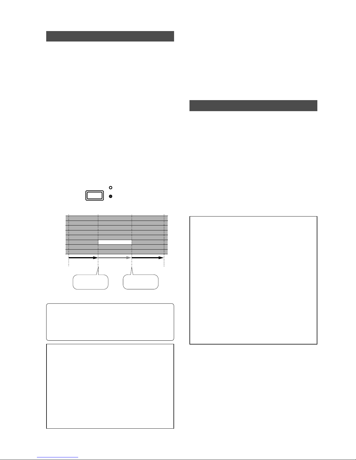
45
Model D2424LVmkII Reference Manual (Punch In/Out)
Auto Punch In/Out Take
After you are satisfied with your rehearsal, you
can proceed to an actual take of Auto Punch
In/Out. You can undo or redo Auto Punch In/
Out recording if you change your mind.
The control panel settings are the same as those
for rehearsal.
(1) Press the [RECORD TRACK] select key [3/11/19]
to set track 3 to READY.
(2) Locate a point slightly before the Auto Punch In
point.
(3) Confirm that Auto Punc h mode is turned on.
Press the [AUT O PUNCH] key to turn on the function,
if it is not already on (REHEARSAL/TAKE LED
flashes).
(4) Press the [RECORD] button while holding do wn
the [PLAY] button.
Only TAKE LED (red) lights up and starts TAKE.
• Track 3 indication on the display will only light up
between the AUTO PUNCH IN/OUT point, and will
flash in any other case.
• When the Auto Punch Out point is passed, the recorder
cancels Auto Punch mode automatically, and nothing
appears in the A. PUNCH display area.
<Caution after Punch Out>
In an FS=44.1kHz program, the simultaneously
recordable number of tracks is a maximum of 8.
In an FS=88.2/96kHz program, the maximum is 2 tracks
in which “seamless punch out” without mute can be
executed.
In simultaneous recording beyond this number, the
recorder will be muted for 3-5 seconds after punch out
but during actual recording, it will be a seamless punch
out. Depending on the speed of the hard disk being
used, when recording a fewer number of simultaneous
tracks than mentioned above, the recorder will also be
muted, but this poses no problem during actual
recording.
Single Undo/Redo
You can single undo or redo Auto Punch In/
Out recording.
Press the [UNDO/REDO] key after recording is
complete to restore the conditions that existed
prior to the recording.
Press the [UNDO/REDO] key again to restore the
conditions that existed after the recording.
However, the procedures explained here is for
Single Undo/Redo and there are limitations as
written in the Notes below. If the current drive
was formatted with the multiple undo function
ON, Multiple Undo is also possible.
Refer to page “69” for details on the Multiple
Undo function.
<Notes at executing single undo/redo>
Note-1
: This function only works when this
recorder is in the stop mode.
Note-2
: After finishing auto punch in/out, please
note that single Undo/Redo is not possible if the
following have been executed.
• If a new recording has been made.
• When a new editing job is executed (such as
Copy & Paste, Move & Paste, or Erase).
• When in the AUTO PUNCH ON mode, when
the AUTO PUNCH IN point is passed in the
PLAY (or RECORD) mode.
• If the power was switched off.
• If program select was executed.
• When multiple undo is executed.
(5) When you finish recording, press the [STOP]
button.
(6) Play track 3 to check the result of the Auto Punch
In/Out operation.
If you fail with AUTO PUNCH IN/OUT and are not
satisfied, repeat the process by performing the
AUTO PUNCH IN/OUT undo operations described
in the next section.
Track 1
Track 2
Track 3
Track 4
Track 5
Track 6
Track 7
Track 8
This part is changed.
Playback end point
Playback start point
Auto punch In point
(Take In)
Auto punch Out point
(Take Out)
All tracks are in playback
monitoring mode.
The recorder punches in
automatically at the
Auto Punch In point.
The recorder punches out
automatically at the
Auto Punch Out point.
Only track 3 in input monitoring,
and data will be recorded.
The RECORD LED lights up
in this area.
All tracks are in playback
monitoring mode.
REHEARSAL
TAKE
AUTO
PUNCH
Page 46
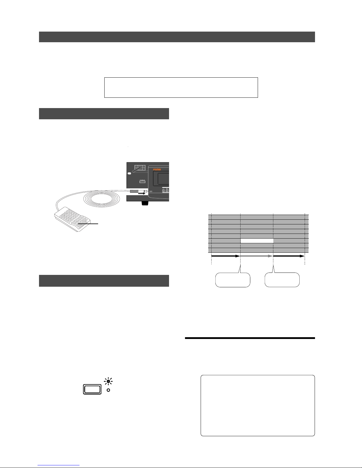
46
Model D2424LVmkII Reference Manual (Punch In/Out)
(6) When you finish rehearsing, press the [STOP]
button.
If you are still unsatisfied, repeat steps 3-5.
Cancelling Rehearsal mode
(1) While holding down the [STOP] button, press the
foot switch.
The display shows “Rehearsal Off” for 1 second, then
the flashing REHEARSAL LED turns off and cancels
the rehearsal mode.
<Hint>: To rehearse repeatedly, set the AUTO
RTN START point slightly before the Punch In
point, and the AUTO RTN END point slightly
before the Punch Out point. This will help you
concentrate on your performance or check the
recording level easily (especially since Manual
Punch In/Out involves operating the foot switch
operation as well as the recorder). (See <Hint-2>
in the “Rehearsing Auto Punch In/Out recording”
for more information.)
Foot switch (unlatch type)
Manual Punch In/Out
This section explains how to perform Manual Punch In/Out using a foot switch.
You do not need to specify the Punch In/Out points. Instead, you press the foot switch at the Punch
In/Out point. Manual Punch In/Out also offers rehearsal and actual takes. You can repeat rehearsal
until you are ready. As an example, replace a part of the recorded guitar solo on track 3.
• Initialize the recorder.
• Select a desired Program for Punch In/Out.
• Check a sampling frequency of the recorder and external device.
Preparation
Check to see that the guitar is connected to the input
jack of the mixer, as required for [AUTO PUNCH IN/
OUT] mentioned earlier.
(1) Connect the foot switch (unlatch type) to the
[PUNCH IN/OUT] jack on the rear panel.
Rehearsing Manual Punch In/Out recording
In Rehearsal mode, the READY track enters input
monitoring mode between the Punch In and Out
points (the points at which you press the foot
switch), and the sound is not recorded. You can
practice the Punch In/Out operation repeatedly
before you proceed to actual recording.
(1) Press the foot switch while holding down the
[STOP] button.
“Rehearsal On” will appear on the display or about
1 second, then rehearsal mode will appear and the
REHEARSAL LED (green) of the [AUT O PUNCH] key
flashes.
(2) Press the [RECORD TRACK] select key [3/11/19]
to set track 3 to READY.
(3) Press the [PLAY] button to play back from a point
slightly before the Punch In point.
(4) Play the guitar accompanying the pla ybac k of
tracks 1 to 8.
The recording level and monitor volume is adjusted
on the mixer in the same manner as done for [AUTO
PUNCH IN/OUT] described earlier.
(5) Press the foot switch once at the desired Punch In
point, then press the foot s witc h again at the
desired Punch Out point.
The rehearsal mode will operate as shown in the
figure. Between the Punch In and Out points the
current performance of the guitar will be played as
the guitar monitor sound. The previous recording
is heard in any other case. The RECORD LED lights
up when Punching In and turn off when Punching
Out (the REHEARSAL LED remains flashing).
(2) Set the foot switch function to “Punch I/O” (punc h
in/out function) by the SETUP mode “Setup of the
foot switch function” menu.
REHEARSAL
TAKE
AUTO
PUNCH
Track 1
Track 2
Track 3
Track 4
Track 5
Track 6
Track 7
Track 8
This part is changed.
Playback end point
Playback start point
Punch In point
(Rehearsal In)
Punch Out point
(Rehearsal Out)
All tracks are in playback
monitoring mode.
Press the foot switch
at the Punch In point.
Only track 3 in input monitoring.
The sound is not recorded
at this time. The RECORD
LED flashes.
All tracks are in playback
monitoring mode.
Press the foot switch
at the Punch Out point.
Page 47
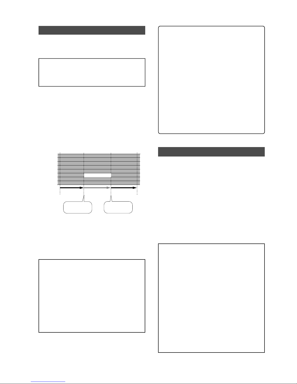
47
Model D2424LVmkII Reference Manual (Punch In/Out)
Manual Punch In/Out take
You can proceed to record if you are satisfied
with the recording level, foot switch timing, and
rehearsal.
<Note>:
You cannot record a second take during the
Manual Punch In/Out operation without stopping the
recorder. That is, the recorder will continue playing
after you finish recording a take, but you cannot record
another take by pressing the foot switch.
(1) Confirm that Rehearsal mode is cancelled, and start
playing the recorder from a point slightly before
the desired Punch In point.
(2) Play the guitar, accompanying the playback of
tracks 1 to 8.
(3) Press the foot switch at the desired Punch In point.
Press the foot switch again at the desired Punch
Out point.
The recorder enters recording mode at the Punch
In point, and cancels recording mode at the Punch
Out point.
(4) Press the [STOP] button.
(5) Play trac k 3 and c hec k the result of Punc h In/Out.
<Hint>
You can use the [PLA Y] button and the [RECORD]
button, instead of using the foot switch.
Follow the steps below.
This method also does not allow you to record
another take unless you stop the recorder first.
Procedure:
1. Press the [PLAY] button to start playback from
a point slightly before the Punch In point.
2. Press the [RECORD] button while holding down
the [PLAY] button at the desired Punch In point.
(Punch In recording starts.)
3. Press the [PLA Y] button at the desired Punch Out
point. (Recording is punc hed out.)
• If you press only the [RECORD] button in both
steps 2 and 3, you can rehearse Punch In/Out.
Single Undo/Redo
You can single undo or redo Manual Punch In/
Out recording.
Press the [UNDO/REDO] key after recording is
complete to restore the conditions that existed
prior to the recording.
Press the [UNDO/REDO] key again to restore the
conditions that existed after the recording.
However, the procedures explained here is for
Single Undo/Redo and there are limitations as
written in the Notes below. If the current drive
was formatted with the multiple undo function
ON, Multiple Undo is also possible.
Refer to page “69” for details on the Multiple
Undo function.
<Notes at executing single undo/redo>
Note-1
: This function only works when this
recorder is in the stop mode.
Note-2
: After finishing manual punch in/out,
please note that single Undo/Redo is not possible
if the following have been executed.
• If a new recording has been made.
• When a new editing job is executed (such as
Copy & Paste, Move & Paste, or Erase).
• When in the AUTO PUNCH ON mode, when
the AUTO PUNCH IN point is passed in the
PLAY (or RECORD) mode.
• If the power was switched off.
• If program select was executed.
• When multiple undo is executed.
Track 1
Track 2
Track 3
Track 4
Track 5
Track 6
Track 7
Track 8
This part is changed.
Playback end point
Playback start point
Punch In point
(Take In)
Punch Out point
(Take Out)
All tracks are in playback
monitoring mode.
Press the foot switch
at the Punch In point.
Only track 3 in input monitorin,
and data will be recorded.
The RECORD LED lights up
in this area.
All tracks are in playback
monitoring mode.
Press the foot switch
at the Punch Out point.
<Caution after Punch Out>
In an FS=44.1kHz program, the simultaneously
recordable number of tracks is a maximum of 8.
In an FS=88.2/96kHz program, the maximum is 2 tracks
in which “seamless punch out” without mute can be
executed.
In simultaneous recording beyond this number, the
recorder will be muted for 3-5 seconds after punch out
but during actual recording, it will be a seamless punch
out. Depending on the speed of the hard disk being
used, when recording a fewer number of simultaneous
tracks than mentioned above, the recorder will also be
muted, but this poses no problem during actual
recording.
Page 48
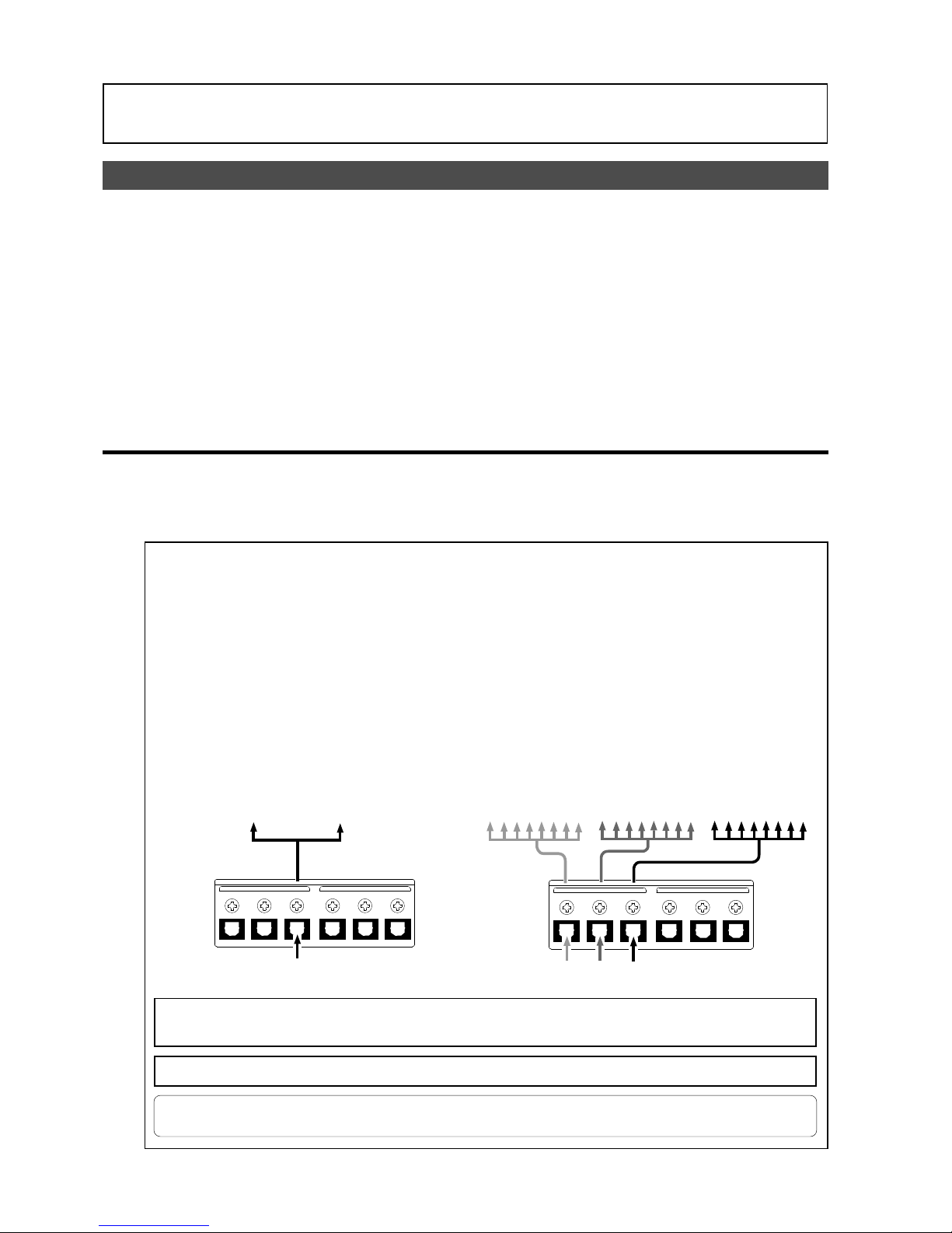
48
Model D2424LVmkII Reference Manual (Recording Digital Data)
Recording Digital Data
Digital recording from an external digital de vice
In addition to multirecording by connection to a digital mixer as explained in the separate “Quick
Operation Guide” manual, the following explains the direct digital recording method by connection
to external digital equipment (CD, MD, DAT, adat, etc.).
When recording digital signals from an external digital equipment, digital signals to be input to the
[DAT A INPUT] connector of the D2424LVmkII must be setup for “S/P DIF” (S/P DIF digital signals) or
“adat” (adat digital signals) in the “Digital Input Setup” menu of the D2424LVmkII SETUP mode.
At the same time, the digital-in clock (Sync mode/async mode) should also be selected and setup
for either sync with external digital signals or with the internal clock. Digital recording can be done
on the currently active program, and “Setup for digital inputs” will be effective on all programs
even when multiple number of programs are currently setup.
• Connecting external digital equipment
(1) Interconnect the [DATA INPUT] connector of D2424LVmkII and [OPTICAL OUT] (or adat OUT) connector of the
external digital equipment with an optical cable.
Depending on the digital signal (S/P DIF or adat) to be recorded, the [DATA INPUT] connector will function as explained
below.
* If the connected external device has only a COAXIAL (RCA pin) jack for digital output, use an optional
Fostex COP-1/96k (optical/coaxial converter).
OUTPUT
DATA
16 - 9
24 - 17
8 - 1
INPUT
16 - 9
24 - 17
8 - 1
OUTPUT
DATA
16 - 9
24 - 17
8 - 1
INPUT
16 - 9
24 - 17
8 - 1
<Notes on interconnecting>
When using the D2424LVmkII [DATA INPUT] connector, it must be set for either S/P DIF digital
signals (optical) or adat digital signals via "Setup of digital inputs" in the SETUP mode.
The connector type is the same for S/P DIF digital signals and adat digital signals but information
content of the digital signal is different. Also, depending on the selected digital signal, each [DATA
INPUT] connector will function as explained below.
<When recording S/P DIF digital signals>
[DATA INPUT] 1-8 only can be used.
By setting the SETUP mode “Setup of digital inputs” to "SPDIF: Async" or "SPDIF: sync," S/P DIF
digital signals that are input to [DATA INPUT] 18 will be assigned to tracks 1 and 2 of the
D2424LVmkII.
<When recording adat digital signals>
[DATA INPUT] 1-8, 9-16, 17-24 can all be used.
By setting the SETUP mode “Setup of digital inputs” to "adat: Async" or "adat: Sync," adat digital
signals input to each input connector will be assigned to each track of the D2424LVmkII.
Tracks 1-2
S/P DIF digital signal
adat digital signal
Tracks 17-24 Tracks 9-16 Tracks 1-8
<Important!>:
Be sure to input a digital signal (S/PDIF or adat) of the same sampling frequency as that
used on the recorder.
<Note>:
The [DATA INPUT] connectors of the unit does not support 96kHz FS adat digital signals.
Page 49
49
Model D2424LVmkII Reference Manual (Recording Digital Data)
• Selecting a recording Program
(2) If you alread y ha ve m ultiple Programs, select the
desired Program using the Program Select
function.
* See page “40” for more information on the
Program Select function.
• Setting the digital input
(3) Set up the digital signal to be input and the digital
in clock at the setup mode “Setup of digital inputs”
menu.
The setting of digital input is initially set to “Analog”
and digital signals cannot be input.
In order to record external digital signals, “SP DIF:
Async,” “SP DIF: Sync,” “adat: Async” or “adat: Sync”
should be setup in accordance to the purpose.
<Notes>
• Do not connect or disconnect the optical cable to
the
[DATA INPUT]
connector when digital input is
assigned. Doing so could generate noise in the
D2424LVmkII and affect the external digital
equipment.
• When the digital input is set to “
adat
” (Async or Sync)
and locked to any one among the three [DATA IN
PUT] (1-8, 9-16, 17-24), “
DIGITAL
” will light in the
display, and the tracks not locked will automatically
change to analog input.
By using this function, analog/digital 24 track
simultaneous recording will be possible by applying
analog signals to tracks 1-8 and adat digital signals
to tracks 9-16 and 17-24.
• Setting recording tracks
(4) Press the [RECORD TRACK] select keys of the
tracks selected in the digital input track menu to
ready the tracks for recor ding.
• Recording
(5) Locate the beginning of the Program.
(6) Make sure that the “DIGITAL” indicators light up
on the screen. While pressing and holding down
the [RECORD] button, press the [PLAY] button to
start recording.
(7) Play the external digital device.
Make sure that the level meter segments light up
and move as the digital signal is being input.
• Completing recording
(8) After you finish recording, stop the recorder and
the connected digital equipment.
"SPDIF:Async":
S/P DIF digital signals from [DATA INPUT] 1-8 will
be assigned to tracks 1 and 2, and the digital
equipment is synchronized with the internal
clock of the D2424LVmkII.
"SPDIF:Sync":
S/P DIF digital signals from [DATA INPUT] 1-8 will
be assigned to tracks 1 and 2, and will be synchronized with the S/P DIF digital signals from
the external digital equipment.
"adat:Async"
adat digital signals from [DATA INPUT] 1-8, 9-16
and 17-24 will be assigned to tracks 1-8, 9-16
and 17-24 respectively, and the digital equipment synchronized with the internal clock of
D2424LVmkII.
"adat:Sync"
adat digital signals from [DATA INPUT] 1-8, 9-16
and 17-24 will be assigned to tracks 1-8, 9-16
and 17-24 respectively, and synchronized with
the adat digital signals from the external digital
equipment.
<Note>:
When the “Setup of digital inputs” is
set to sync mode of “
SPDIF: sync”
or “
adat: Sync”
,
the SETUP mode "
Clock Sel?
" setting will be ignored and the digital-in clock will have priority.
In this case, "
DIGITAL"
and "
EXT
" will light up in
the "
CLOCK
" section of the display.
<Hint!>
When a “Digital 0 (zero)” signal is input during
digital recording under the SETUP mode “Zero
File?” menu, whether or not a “0 file” should be
recorded or not can be setup. Although the “Zero
File?” menu is initially set to “Enable,” by chang-
ing this to “Disable,” a “0 file” will not be registered and the digital signal to be recorded can
be made as “one file.”
For details on the “Zero File?” menu, refer to
page “127.”
If digital input is set to "Analog," "SPDIF: Async"
or "adat: Async," the SETUP mode "Clock Sel?"
(setup of operating clock) must be set up.
* Refer to page “
117
” for setup of “D.in?” menu.
Page 50
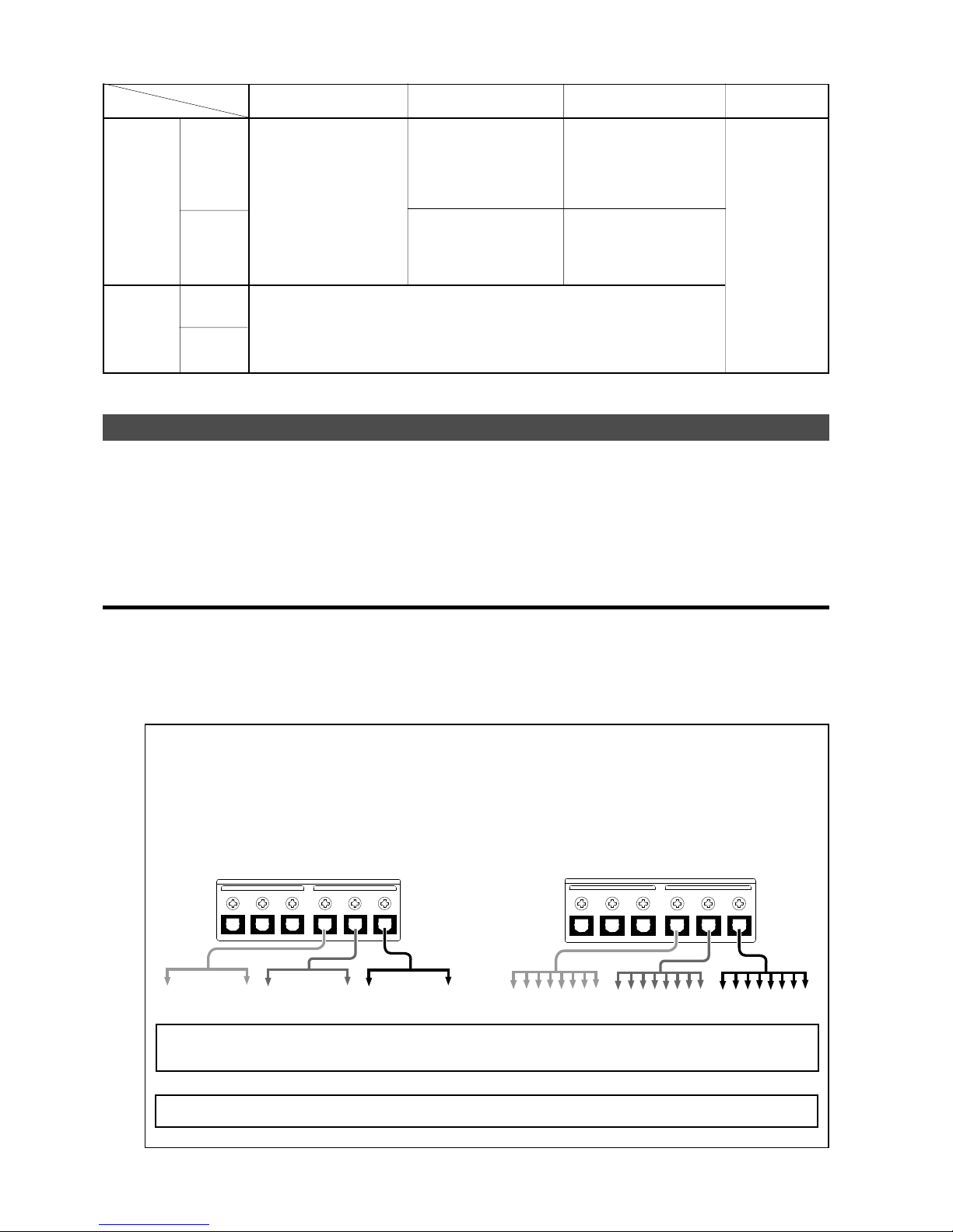
50
Model D2424LVmkII Reference Manual (Recording Digital Data)
Digital recording to external digital equipment
Tunes recorded on the D2424LVmkII can be recorded on external digital equipment such as MD,
DAT, CD-R or adat. In order to digital record to external digital equipment, digital signals to be
output at the D2424LVmkII [DAT A OUTPUT] connector must be set to “SP DIF” or “adat” (The initial
setup is “adat.”) by the “Setup of digital output” menu in the D2424LVmkII SETUP mode.
The currently active program can be digitally recorded and “Setup of digital outputs” will be common
to all programs.
• Connecting external digital equipment
(1) Use an optical cable to connect the [DAT A OUTPUT] connector of the recor der to the OPTICAL IN (or adat IN) jac k
of the external digital equipment.
Set the external equipment input port to “digital” so that digital signals can be input.
Because some digital equipment must be externally synchronized against digital signals, in addition to setting the
input port to “digital,” be sure to refer to the operating manual of any digital equipment to be used.
Depending on the digital signal that is output, the [DATA OUTPUT] connector will function as explained below.
SPDIF :Async
SPDIF :Sync
adat :Async
adat :Sync
[D. in ?] setting
[Clock Sel ?]
setting
Int
Auto
Word
Video
clock received
from WORD IN
Available only
when installing
the optional
Model 8346 TC/
SYNC card. If you
try to select
“Video,” “Void w/
o 8346” is displayed and you
cannot select it.
See the appendix
of the Reference
manual for details.
Regardless of receiving or not
receiving word clock from
WORD IN, the recorder is referenced to the internal clock.
When the recorder receives
correct digital signals, the
“DIGITAL” indicator lights in
the display.
When receiving word clock
from WORD IN, the recorder
automatically synchronizes to
the incoming clock, while the
“DIGITAL” and “EXT” indica-
tors light in the display.
When receiving word clock
from WORD IN, the recorder
synchronizes to the incoming
clock, while the “DIGIT AL ” and
“EXT” indicators light in the dis-
play .
Regardless of receiving or not receiving word clock from WORD IN, the recorder synchronizes to the external S/P DIF digital signal. When the recorder receiv es correct digital signals ,
the “DIGITAL ” and “EXT” indicators light in the display. When Digital In is set to a SYNC mode,
if you try to select “Clock Sel?” menu, The display will show “Clock Sel D.in!” (indicating that
the clock is set to Digital In!) and the recorder ignores your operation.
no clock
received from
WORD IN
no clock
received from
WORD IN
clock received
from WORD IN
When no word clock is received, the recorder is referenced to the internal clock,
while the “EXT” indicator
flashes.
When no word clock is received, the “EXT” indicator
flashes showing that the unit
cannot be locked.
OUTPUT
DATA
16 - 9
24 - 17
8 - 1
INPUT
16 - 9
24 - 17
8 - 1
OUTPUT
DATA
16 - 9
24 - 17
8 - 1
INPUT
16 - 9
24 - 17
8 - 1
<Notes on interconnecting>
[DATA OUTPUT] of the D2424LVmkII must be setup for S/P DIF digital signals (optical) or adat digital
signals by the "Setup of digital output" menu in the SETUP mode. Although the connector type is
same for both S/P DIF digital and adat digital signals, their information content is different.
Depending on the digital signal selected, the following signals are output from each output connector.
<At output of S/P DIF digital signals>
<At output of adat digital signals>
Output of tracks 5-6
Output of tracks 3-4 Output of tracks 1-2
Output of tracks 17-24
Output of tracks 9-16 Output of tr ac ks 1-8
<Important!>:
Be sure to output a digital signal (S/PDIF or adat) of the same sampling frequency as that
used on the recorder.
<Note>:
The [DATA OUTPUT] connectors of the unit does not support 96kHz FS adat digital signals.
Page 51
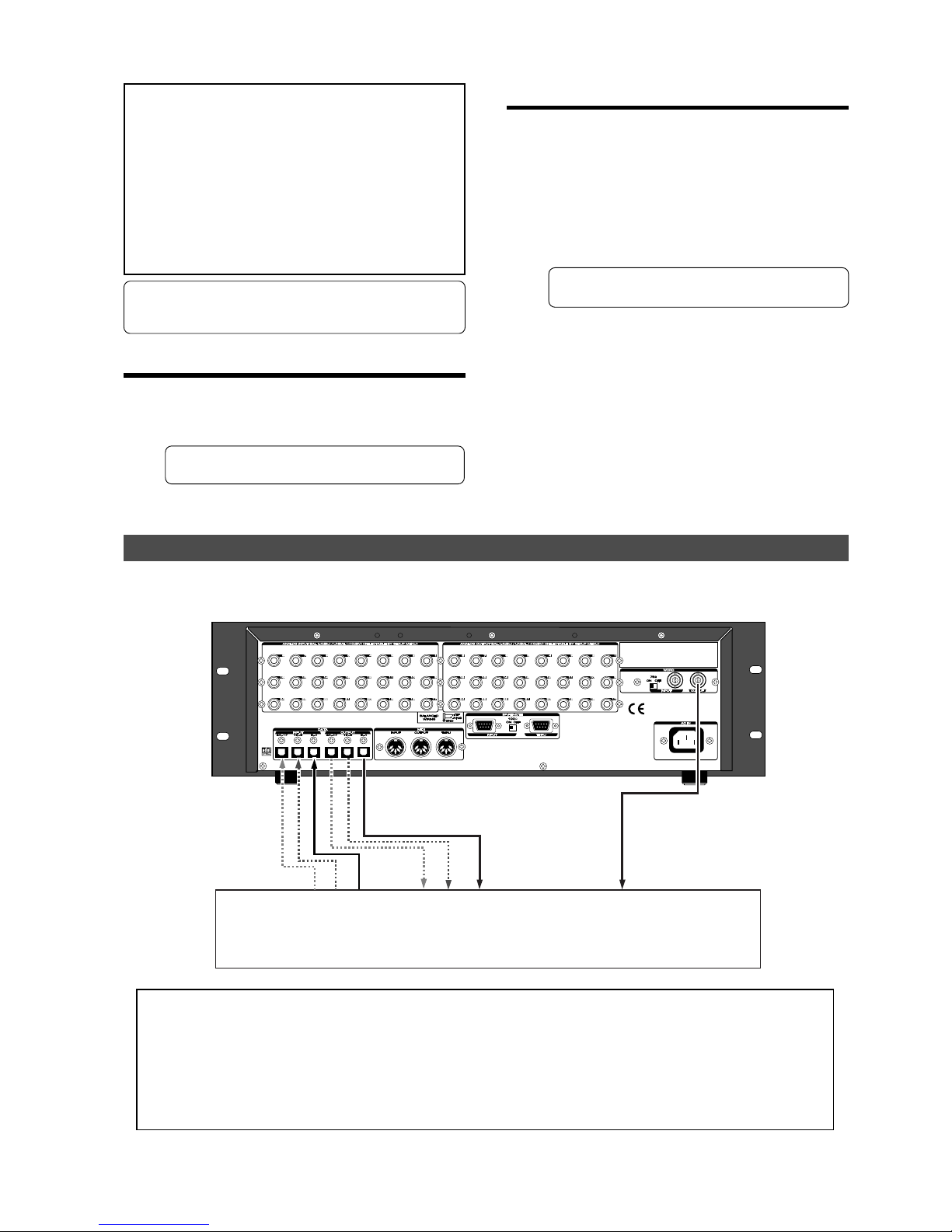
51
Model D2424LVmkII Reference Manual (Recording Digital Data)
Use the digital output setup menu in Setup
mode to assign output tracks.
With the default setting, the digital output is
set to “adat”. You can select “adat” or “SP DIF”.
To output adat digital signals to a connected
adat device, select “adat.” To output S/P DIF
signals to a connected CD-R, MD, or DAT
recorder, select “SP DIF.”
• Setting the digital output
* See page “
118
” for more information on the
“D. out?” menu.
When you finish setting the parameters in
Setup mode, press the [EXIT/NO] key or the
[STOP] button to exit Setup mode.
Connecting a Digital Mixer
The following explanations assume that this is digital mixer, which can input digital signals whose
clock source can be setup at digital in.
• Selecting a recording Program
(2) If you already have multiple Programs, select the
desired Program using the Program Select
function.
* See page “40” for more information on the
Program Select function.
<Notes>
• Connecting the recorder to an external digital device
via both digital input and output jacks may generate
a digital loop.
•
Data on the additional tracks cannot be digitally
recorded to the external device as it is. To output
digital data from the additional track, move it to the
real tracks first, then output it to the external device
(using the Track Exchange function).
For more information on the Track Exchange function,
see page “
77
.”
* If the connected external device has only a COAXIAL
(RCA pin) jack for digital input, use an optional Fostex
COP-1/96k (optical/coaxial converter).
Digital Mixer
<Precaution against the digital loop>
When interconnecting D2424LVmkII and a digital mixer as shown in above schematic, if the
D2424LVmkII “
Setup of the digital input
” is set to
adat
or “
Sync
” (synchronous mode) of S/P DIF, and
the digital mixer clock source is set to “
DIGITAL IN
,” a digital loop will be created and it will not
operate correctly.
In such a case, setup the D2424LVmkII “
Setup of the digital input
” to
adat
or “
Async
” (asynchronous
mode) of S/P DIF.
Word In
Digital In
Digital Out
Page 52
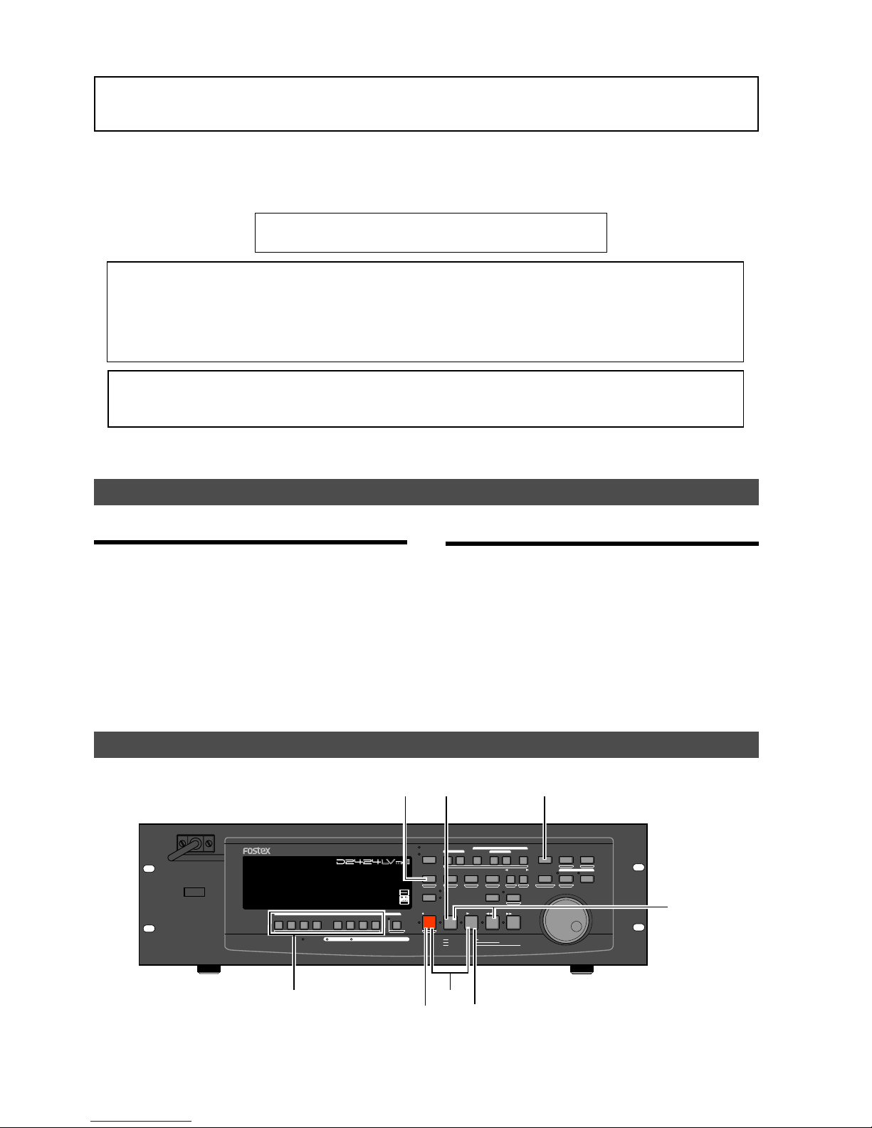
52
Model D2424LVmkII Reference Manual (Recording to a Metronome Sound)
• Creating a Tempo Map
(1) Set the time signature using the “Setting a time
signature” menu in SETUP mode.
Refer to the “Setting a time signature” section on
page “110.”
(2) Set a tempo for a given point using the “Setting a
tempo” in SETUP mode.
Refer to the “Setting a tempo” section on page “112.”
• T urning the Metr onome function on
(3) Turn the Metr onome function on using the “Setting
the Metronome function” menu in SETUP mode.
Refer to the “Setting the Metronome function”
section on page “113.”
Recording to a Metronome Sound
This chapter explains how to record your performance while you are playing an instrument
accompanied by a metronome based on the time signature and tempo specified in the Tempo Map.
The metronome sound is output from track 24 on the D2424LVmkII.
• Initialize the recorder before the operation.
• If multiple Programs exist, first select the desired Program.
<Notes>
* With the metronome function ON and the RECORD TRACK select key for the track (track 24) to which the
metronome sound is to be output set to READY, an attempt to record you cannot record to this track.
Also, information which had already been recorded on this track cannot be played back.
* Always switch off the Metronome function setting in the SETUP mode after finishing.
<Please remember this!>
In D2424LVmkII which had been formatted to 96kHz/24bit or 88.2kHz/24bit (Real track 1-8) the metronome
sound will be output from track 24. Therefore, Real tracks 1-8 can all be used for normal recording/playback.
POWER
HOLD
RECORD
STOP
PLAY
REW
F FWD
ALL INPUT
ALL READY
LOCATE REC END
VARI PITCH
PUNCH
LOCATE
REHEARSAL
TAKE
RECALL
STORE
EXIT/NO
EXECUTE/YES
PGM SEL
NEXT
PREV
UNDO/REDO
PREVIEW
EDIT SETUP
AUTO RTN
OUTIN
AUTO PLAY
START
OUTIN
END
17-24
ACCESS
9-16
1/9/17
2/10/18
3/11/19
4/12/20 5/13/21 6/14/22 7/15/23
8/16/24
FOOT SW
LOCATE ABS 0
CLIPBOARD PLAY
AUTO
TRACK SHIFT
SHIFT
DISP SEL
CHARACTER
TIME BASE SEL
P.EDIT
EJECT
ENVELOPE
CHASE
TC READY TC GEN M.UNDO
TRACK SHIFT
PREV TC
NEXT TC
RECORD TRACK
CLIPBOARD
AUTO PUNCH
AUTO RTN
LOCATE MEMORY
24bit
96kHz
OPTICAL
24TRACK DIGITAL RECORDER
5, 13
6
10
2, 7
4, 9, 14
1
12
1
Preparation
Recording to a metronome sound
Page 53

53
Model D2424LVmkII Reference Manual (Recording to a Metronome Sound)
• Checking the metronome sound
(1) Press the [DISP SEL] key while holding down the
[SHIFT] key to switch the time base in adv ance to
BAR/BEAT/CLK.
(2) Start playback from the beginning of the Program.
Even if the selected Program does not have any
recorded data, track 24 outputs the metronome
sound and the unit counts time.
(3) Adjust the system so the sound output from track
24 can be monitored with the mixer.
You will hear the metronome sound output from
track 24 using the Tempo Map created earlier.
(4) After confirming the metronome sound, stop the
recorder section and return to the top Program.
• Adjusting monitor/record level of the musical
instrument
(5) Press the [RECORD TRACK] select ke y of the track
to record the musical instrument on, and then put
that track in the READY mode.
(6) Press the [RECORD] button.
The LED of the [RECORD] button will flash and the
READY track will go to the input monitor mode.
(7) Press the [PLA Y] button and pla yback the Program
from the top.
Only the READY track will go to the input monitor
mode (recording does not take place), and all other
tracks will be in the reproduction monitor mode,
therefore track 24 plays back the metronome sound.
(8) Play the musical instrument in time with the
metronome and adjust the recording level of the
track to be recorded on the mixer.
(9) After adjusting the recording level, stop the
recorder and return to the top of the Program.
• Starting recording
(10) Hold down the [RECORD] button and press the
[PLAY] button to start recording.
The READY track will go to the input monitor mode
just as when the recording level was adjusted.
The time the level that was actually adjusted with
the mixer will be recorded.
(11) Play the musical instrument in time with the
metronome.
• Quitting recording
(12) Press the [STOP] button to stop the recorder .
(13) Turn OFF the ready track [RECORD TRACK] select
key .
(14) Locate the top of the Program and start playback.
Adjust and monitor the track playback sound
recorded on the mixer.
Since the metronome function still remains ON at
this time, you can hear the metronome sound
during playback of the recorded sounds when you
turn up the track 24 monitor volume.
• Checking the recorded sound
• If you wish to redo the recording, repeat the
recording after executing “undo” by using the
single undo/redo or multiple undo functions.
Page 54
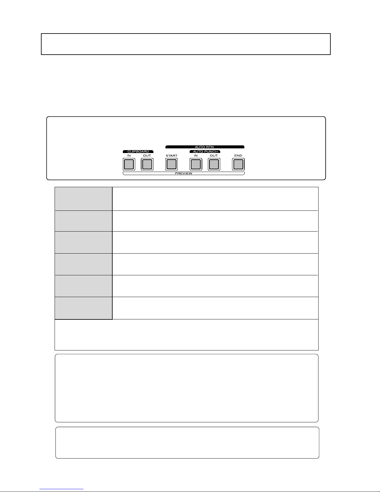
Model D2424LVmkII Reference Manual (Storing a Locate Point (Edit Point)
54
Storing a Locate P oint (Edit Point)
[AUTO PUNCH IN] ke y
[AUTO PUNCH OUT] ke y
[CLIPBOARD IN] key
[CLIPBOARD OUT] key
[AUTO R TN START] key
[AUTO R TN END] key
You can store specific individual time data (time, bar/beat/clock) in each memory key (*).
The time data stored is used as an “Editing Point” to execute “Locate Point” or Auto Punch In/Out, Copy & Paste,
Move & Paste or Erase. You can also store 99 (Locate Number 01-99) time data in the [LOCATE] key, in
addition to the Memory key, to enable locate only features. This chapter will describe how to store specific data
in the memory key and how to edit and re-store data is already stored in the memory key. The data stored in
each memory are used for the following operations.
Also, the 99 locate memories can be used for the Mark STOP memory. For details, refer to "Setup of stop
function at the mark point" in the SETUP mode.
* Memory key
When you set the IN/OUT points for Auto Punch In/Out, IN/OUT points for Copy & Clip/Move & Clip, and
START/END points for Auto Return/Auto Repeat, END points.
• Locating the AUTO PUNCH IN point.
• Recording start point for the Auto Punch In/Out operation.
• Paste start point for the Copy & Paste or Move & Paste operation.
• Erase start point for the Erase operation.
• Locating the AUTO PUNCH OUT point.
• Recording end point for the Auto Punch In/Out operation.
• Erase end point for the Erase operation.
• Locating the CLIPBOARD IN point.
• Copy start point for copying or moving data to the clipboard during the Copy & Paste or Move
& Paste operation.
• Locating the CLIPBOARD OUT point.
• Copy end point for copying or moving data to the clipboard during the Copy & Paste or Move
& Paste operation.
• Locating the AUTO RTN START point.
• Locate end point from AUTO RTN END in Auto Return or Auto Repeat modes.
• Locating the AUTO RTN END point.
• Locate start point to AUTO RTN START in Auto Return or Auto Repeat modes.
<Note on storing the locate point>
When you set the IN/OUT points for Auto Punch In/Out, IN/OUT points for Copy & Clip/Move & Clip, and
START/END points for Auto Return/Auto Repeat, make sure that IN points precede the OUT points and
START points precede the END points.
You can also store time data in the [LOCATE] key, in addition to each memory key explained above.
You can store up to 99 individual time data in the [LOCATE] key for locate only features. Store the
data by specifying Locate Number to locate the intended time data. Note that the [LOCATE] key
always stores the last located time data in real-time. This Locate Number is stored as 00, and does not
require a Locate Number specification to locate it.
Simply pressing the [LOCA TE] key directly, will locate that data. This becomes an advantage since it is
possible to repeatedly locate the last located point.
You can edit the data stored in the [LOCA TE] key, as so with the data stored in the Memory key. For
more details refer to page “56.”
• You can store locate points for each Program. (You need to select a Program first.)
• When executing save/load of song data via the compactFlash
TM
card (or an optional E-IDE hard disk
drive), these data can be directly saved/loaded. Save/load by DAT and adat cannot be done.
• All locate points stored in the memory keys will be maintained after you turn off the recorder.
Page 55
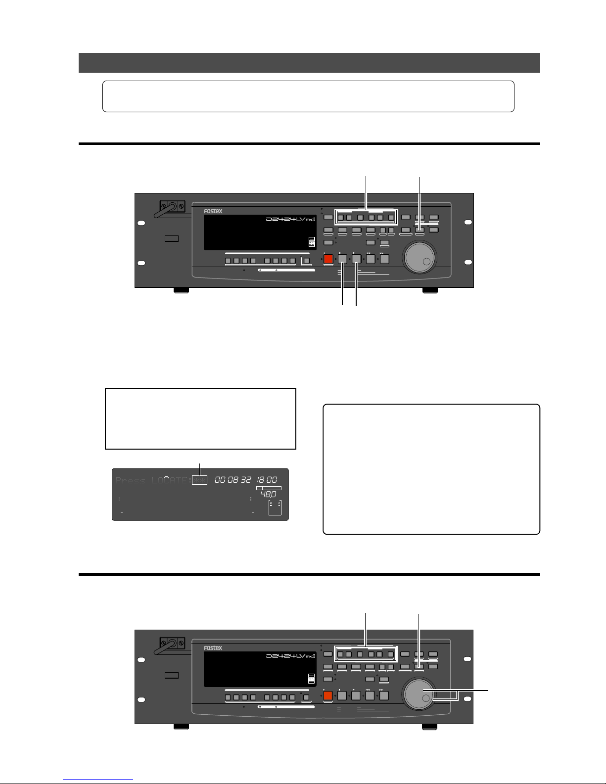
Model D2424LVmkII Reference Manual (Storing a Locate Point (Edit Point)
55
Flashing
Storing and editing the locate points to the memory keys
• Select the desired Time Base using the
[DISP SEL]
key and
[SHIFT]
key an if you wish to use a Time
Base other ABS.
• The stored or edited locate points are used only in the currently-selected Program.
Storing in real-time
You can store the locate point (in the ABS, MTC, or BAR/BEAT/CLK Time Base) in real-time while the
recorder is playing.
(1) Press the [PLAY] button to play back data.
(2) When the point you wish to store is reached, press
the [STORE] key.
The time value or bar/beat/clock value of the point
is captured. The recorder enters data edit mode.
<Note>:
The following menu (##=number from
00-99) appears when pressing the
[STORE]
key.
This menu is used to store data in the
[LOCATE]
key, described later. Ignore this menu and go to
the next step when storing data in the memory
key.
(3) Press the desired memory key.
The STORE LED turns off.
The captured time value (or bar/beat/clock value)
is stored in the memory key. After the data is stored,
the recorder displays the previous Time Base and
continues playback.
(4) Press the [STOP] button.
<Please remember this!>
• If you set “BAR/BEAT Resolution mode” in SETUP
mode to ON, the recorder will round off the CLK value
of the captured bar/beat/clock value. That is, the
locate point will be at the beginning of the beat (00).
Refer to page “119” for more information.
• When pressing the [STORE] key in step 2, if the
[STORE] key is pressed while holding down the
[SHIFT] key, data to be registered will be held and be
confirmed. To register data after confirmation, press
the [STORE] key again and press the desired memory
key.
Editing and storing data
You can recall data stored in the memory key, edit it, and store it again.
FSMH
∞
42
OL
0
30
24
18
12
9
6
3
kHz
24
FS
BIT
SF
24
∞
42
OL
0
30
24
18
12
9
6
3
LOCATE
232221201918
17
16151413121110
98765
4
3
2
1
CLOCK
INT
POWER
HOLD
RECORD
STOP
PLAY
REW
F FWD
ALL INPUT
ALL READY
LOCATE REC END
VARI PITCH
PUNCH
LOCATE
REHEARSAL
TAKE
RECALL
STORE
EXIT/NO
EXECUTE/YES
PGM SEL
NEXT
PREV
UNDO/REDO
PREVIEW
EDIT SETUP
AUTO RTN
OUTIN
AUTO PLAY
START
OUTIN
END
17-24
ACCESS
9-16
1/9/17
2/10/18
3/11/19
4/12/20 5/13/21 6/14/22 7/15/23
8/16/24
FOOT SW
LOCATE ABS 0
CLIPBOARD PLAY
AUTO
TRACK SHIFT
SHIFT
DISP SEL
CHARACTER
TIME BASE SEL
P.EDIT
EJECT
ENVELOPE
CHASE
TC READY TC GEN M.UNDO
TRACK SHIFT
PREV TC
NEXT TC
RECORD TRACK
CLIPBOARD
AUTO PUNCH
AUTO RTN
LOCATE MEMORY
24bit
96kHz
OPTICAL
24TRACK DIGITAL RECORDER
41
3
2
POWER
HOLD
RECORD
STOP
PLAY
REW
F FWD
ALL INPUT
ALL READY
LOCATE REC END
VARI PITCH
PUNCH
LOCATE
REHEARSAL
TAKE
RECALL
STORE
EXIT/NO
EXECUTE/YES
PGM SEL
NEXT
PREV
UNDO/REDO
PREVIEW
EDIT SETUP
AUTO RTN
OUTIN
AUTO PLAY
START
OUTIN
END
17-24
ACCESS
9-16
1/9/17
2/10/18
3/11/19
4/12/20 5/13/21 6/14/22 7/15/23
8/16/24
FOOT SW
LOCATE ABS 0
CLIPBOARD PLAY
AUTO
TRACK SHIFT
SHIFT
DISP SEL
CHARACTER
TIME BASE SEL
P.EDIT
EJECT
ENVELOPE
CHASE
TC READY TC GEN M.UNDO
TRACK SHIFT
PREV TC
NEXT TC
RECORD TRACK
CLIPBOARD
AUTO PUNCH
AUTO RTN
LOCATE MEMORY
24bit
96kHz
OPTICAL
24TRACK DIGITAL RECORDER
1, 4 3
2
Page 56
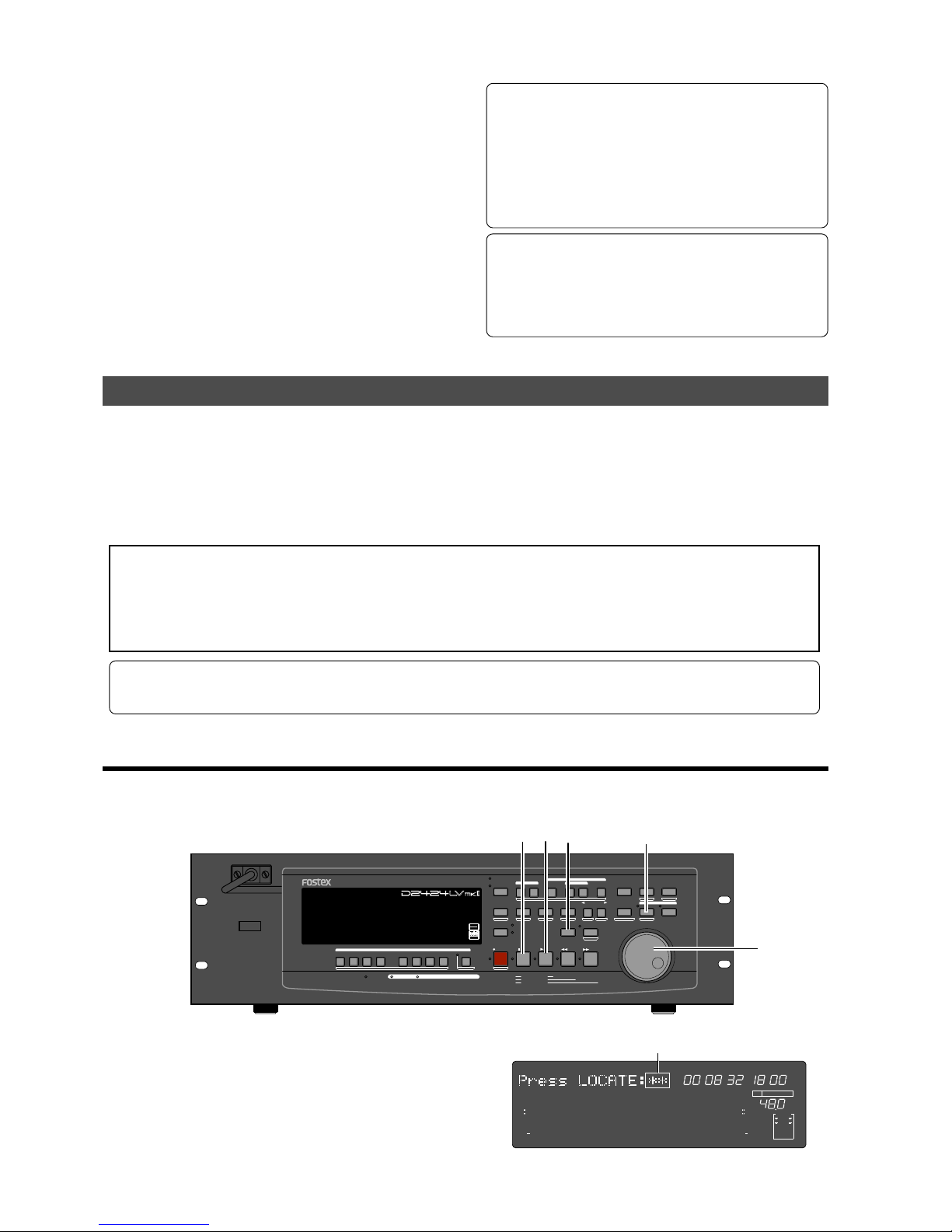
Model D2424LVmkII Reference Manual (Storing a Locate Point (Edit Point)
56
Flashing
(1) While the recorder is stopped, press the memory
key that stores the data you wish to edit.
The stored data appears on the display and the
recorder enters data edit mode.
(2) T urn the Shuttle dial to move the flashing cur sor to
the time value digit, and use the Jog dial to increase
or decrease the value.
(3) Press the [STORE] ke y.
The “Press LOCA TE: ##” menu will appear as
indicated before. Ignore this go to the next step.
(4) Press the memory key that you pressed in Step 1
again.
The STORE LED will turn off. The edited data is
stored, and the recorder displays the previous Time
Base indication.
• You can store the edited data in a memory key other
than the one you pressed when you recalled the data.
For example, you can recall the AUTO PUNCH IN point
data, edit it, and store it to the
[AUTO PUNCH OUT]
key.
• You can also use the Preview function to edit the
stored locate points (edit points). Refer to “
Preview
Function
” on page “67” for more information.
• Refer to page “43” for more information on Auto
Punch In/Out.
• Refer to page “
71
” for more information on Copy &
Paste, Move & Paste, and Erase.
• Refer to page “
58
” for more information on Auto
Return and Auto Repeat.
Storing and editing [LOCATE] key
You can store up to 99 individual time data in the [LOCA TE] key for Locate only operations.
The time data stored can also be assigned with a specific locate number from 01-99.
This means the desired locate number can be specified to locate that specific time data.
The memory data of the [LOCATE] key can also be edited in the same manner as the data in the
Memory key. After editing the data the [LOCA TE] key can locate that point, or even be re-stored as
data for other Memory keys.
<Notes>
• The last data located with the Memory key or
[LOCATE]
key is constantly stored as LOCATE number 00.
However, this data is constantly replaced after every LOCATE command. Therefore, do not use Locate Number 00
for independent Locate data.
• You cannot preview the data stored in the
[LOCATE]
key, though it is possible to preview data stored in other
Memory keys.
* If you use a time base that is not an ABS time, there is a need to priory switch to the desired time base using the
[SHIFT]
key and
[DISP SEL]
key.
* Any editing or storing of data for the LOCATE point is valid only for the program that is currently started up.
Storing in real-time
You can store the locate point (in the ABS, MTC, or BAR/BEAT/CLK Time Base) in real-time while the
recorder is playing.
FSMH
∞
42
OL
0
30
24
18
12
9
6
3
kHz
24
FS
BIT
SF
24
∞
42
OL
0
30
24
18
12
9
6
3
LOCATE
232221201918
17
16151413121110
98765
4
3
2
1
CLOCK
INT
POWER
HOLD
RECORD
STOP
PLAY
REW
F FWD
ALL INPUT
ALL READY
LOCATE REC END
VARI PITCH
PUNCH
LOCATE
REHEARSAL
TAKE
RECALL
STORE
EXIT/NO
EXECUTE/YES
PGM SEL
NEXT
PREV
UNDO/REDO
PREVIEW
EDIT SETUP
AUTO RTN
OUTIN
AUTO PLAY
START
OUTIN
END
17-24
ACCESS
9-16
1/9/17
2/10/18
3/11/19
4/12/20 5/13/21 6/14/22 7/15/23
8/16/24
FOOT SW
LOCATE ABS 0
CLIPBOARD PLAY
AUTO
TRACK SHIFT
SHIFT
DISP SEL
CHARACTER
TIME BASE SEL
P.EDIT
EJECT
ENVELOPE
CHASE
TC READY TC GEN M.UNDO
TRACK SHIFT
PREV TC
NEXT TC
RECORD TRACK
CLIPBOARD
AUTO PUNCH
AUTO RTN
LOCATE MEMORY
24bit
96kHz
OPTICAL
24TRACK DIGITAL RECORDER
5
2
3
1
4
(1) Press the [PLAY] button to start playback.
(2) Press the [ST ORE] key (the ST ORE LED lights up).
The memory number selection menu will appear,
as follows.
Page 57
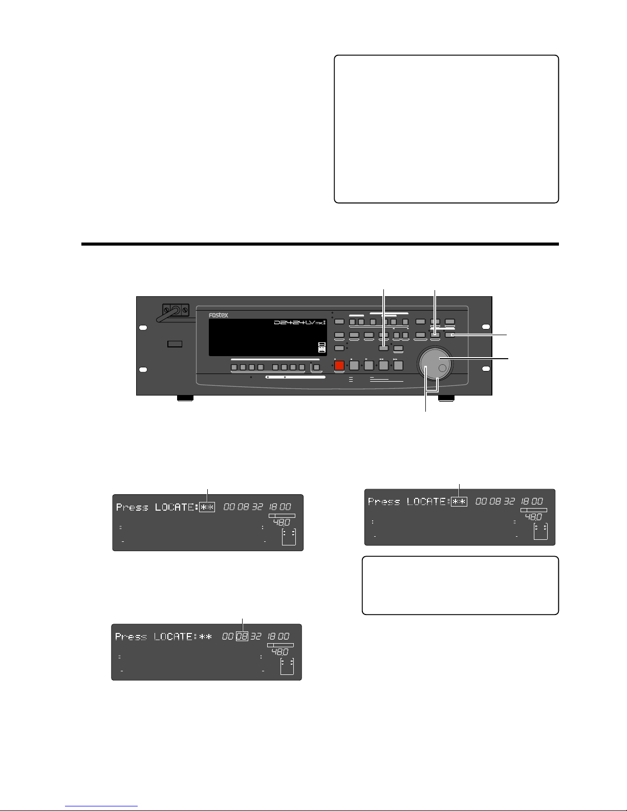
Model D2424LVmkII Reference Manual (Storing a Locate Point (Edit Point)
57
(3) Select the LOCATE number desired using the Jog
dial.
LOCATE number from 00-99 are selectable.
However, select a number other then 00.
(4) Next press the [LOCATE] key .
The time base (or bar/beat/clock) put on hold is
stored as data in the LOCATE number selected.
The system will return to the original time base
when the storage process is completed, and
playback is resumed.
(5) After completing the store process, press the
[STOP] button to stop the recorder section.
<Please remember this!>
• If you set “BAR/BEAT Resolution mode” in SETUP
mode to ON, the recorder will round off the CLK value
of the captured bar/beat/clock value.
That is, the locate point will be at the beginning of
the beat (00).
Refer to page “119” for more information.
• When pressing the [STORE] key in step 2, if the
[STORE] key is pressed while holding down the
[SHIFT] key, data to be registered will be held and be
confirmed. To register data after confirmation, press
the [STORE] key again and press the desired memory
key.
Edit and re-store data that is already stored
RECALL the desired time data already stored in the [LOCA TE] key, edit that data and re-store it.
(1) Press the [RECALL] key while the recorder is
stopped.
The menu to select the LOCATE number will appear.
(2) T urn the Jog dial to select the desired LOCATE
number , then press the [LOCATE] key.
The data edit mode will appear when the data stored
in the selected LOCATE number appears.
(3) T urn the Shuttle dial to move the (cursor) column
of the time indication to edit (cursor flashing point),
increase or decrease the number setting with the
Jog dial or input the desired time base.
Flashing
Flashing
(4) Press the [STORE] key (the ST ORE LED lights up).
The LOCATE number selection menu to store data
will appear.
(5) You can use the Jog dial to input the desired
LOCA TE n umber.
(6) Press the [LOCATE] key.
The edit time data is stored as the time data for the
selected LOCATE number.
Flashing
• If the [STORE] key is press instead of the
[LOCA TE] key at this stage, it becomes possible
to directly LOCATE the time data of the
selected LOCATE number. For more details
refer to the next section on “Locate Functions.”
FSMH
∞
42
OL
0
30
24
18
12
9
6
3
kHz
24
FS
BIT
SF
24
∞
42
OL
0
30
24
18
12
9
6
3
LOCATE
232221201918
17
16151413121110
98765
4
3
2
1
CLOCK
INT
FSMH
∞
42
OL
0
30
24
18
12
9
6
3
kHz
24
FS
BIT
SF
24
∞
42
OL
0
30
24
18
12
9
6
3
LOCATE
232221201918
17
16151413121110
98765
4
3
2
1
CLOCK
INT
FSMH
∞
42
OL
0
30
24
18
12
9
6
3
kHz
24
FS
BIT
SF
24
∞
42
OL
0
30
24
18
12
9
6
3
LOCATE
232221201918
17
16151413121110
98765
4
3
2
1
CLOCK
INT
POWER
HOLD
RECORD
STOP
PLAY
REW
F FWD
ALL INPUT
ALL READY
LOCATE REC END
VARI PITCH
PUNCH
LOCATE
REHEARSAL
TAKE
RECALL
STORE
EXIT/NO
EXECUTE/YES
PGM SEL
NEXT
PREV
UNDO/REDO
PREVIEW
EDIT SETUP
AUTO RTN
OUTIN
AUTO PLAY
START
OUTIN
END
17-24
ACCESS
9-16
1/9/17
2/10/18
3/11/19
4/12/20 5/13/21 6/14/22 7/15/23
8/16/24
FOOT SW
LOCATE ABS 0
CLIPBOARD PLAY
AUTO
TRACK SHIFT
SHIFT
DISP SEL
CHARACTER
TIME BASE SEL
P.EDIT
EJECT
ENVELOPE
CHASE
TC READY TC GEN M.UNDO
TRACK SHIFT
PREV TC
NEXT TC
RECORD TRACK
CLIPBOARD
AUTO PUNCH
AUTO RTN
LOCATE MEMORY
24bit
96kHz
OPTICAL
24TRACK DIGITAL RECORDER
4
2, 5
2, 6
3
1
Page 58
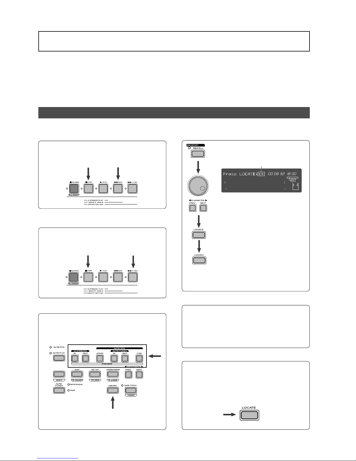
Model D2424LVmkII Reference Manual (Locate Function)
58
Locate Function
The recorder swiftly locates (it moves the current location of the recorder section) the desired
point when necessary. Locate include edit points (in ABS time, MTC time, or in bar/beat/clock) that
are stored for the Copy, Move, Paste, Erase, or Auto Punch In/Out operations.
They also include Locate by specifying a voluntary time, and Locate specifying a voluntary Locate
Number (01-99), as well as Locate directly to the recording end point in a Program (REC END).
An application of he Locate function includes auto functions such as Auto Play, Auto Return and
Auto Repeat.
Direct Locate
The Direct Locate function enables you to locate the following points:
• Locate the beginning of the Program (LOCATE ABS 0)
Press the [REWIND] button while holding down the
[STOP] button.
The recorder will immediately locate the beginning of
the currently-selected Program.
• Locate the recording end point of the Program (LOCATE
REC END)
Press the [F FWD] button while holding down the
[STOP] button.
The recorder will immediately locate the end point of
the currently-selected Program.
• Locate the position stored in one of the memory keys
Press the desired memory key , then press the [LOCA TE]
key .
The recorder will locate the point (edit point) stored in
the corresponding memory key immediately.
The located time data is always stored as time data in
Locate Number 00.
• Specify the Locate Number to locate data
1. Press the [RECALL] key.
The Locate Number selection menu
appears.
2. Turn the Jog dial or press the [NEXT]
key / [PREV] key to select the desired
number.
3. Press the [LOCATE] key once.
The time stored in the selected Locate
Number appears.
4. Press the [LOCATE] key again.
The time data of the selected LOCATE number is swiftly
located. The located time data is constantly stored as
time data in Locate Number 00.
• Locate a specified point
Refer to “Editing and storing locate data” in the chapter
“Storing a Locate Point (Edit Point)” for information
on how to edit the data and on pressing the [LOCATE]
key instead of the [STORE] key.
The point at specified time value (or bar/beat/clock
value) will be located immediately.
• Locate the last-located point
Directly press the [LOCATE] key.
The time data of Locate number 00 is located. Locate
number 00 is always update with the last data located
(excluding LOCATE ABS 0 and LOCATE REC END).
Therefore, you will locate the data in memory number
00 every time you directly press the [LOCA TE] key.
FSMH
∞
42
OL
0
30
24
18
12
9
6
3
kHz
24
FS
BIT
SF
24
∞
42
OL
0
30
24
18
12
9
6
3
LOCATE
232221201918
17
16151413121110
98765
4
3
2
1
CLOCK
INT
Flashing
Page 59
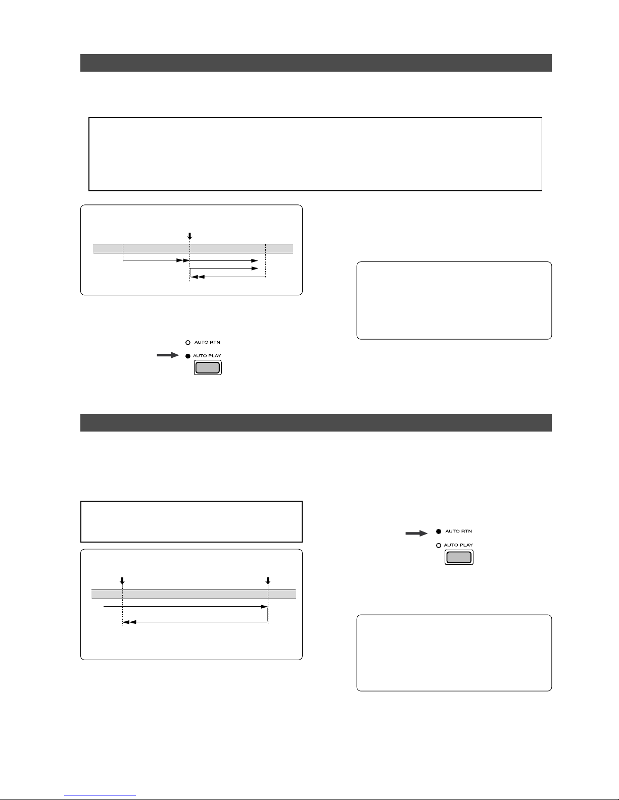
Model D2424LVmkII Reference Manual (Locate Function)
59
AUTO PUNCH IN point
LOCATE
PLAYBACK
LOCATE
PLAYBACK
LOCATE
START
LOCATE
START
AUTO RTN END point
AUTO RTN START point
STOP
PLAYBACK
LOCATE
PLAYBACK
START
Auto Play function
The Auto Play function allows the recorder to start play back automatically from the located point.
AUTO PLAY mode should be turned on before you execute the Direct Locate function described
above.
<Notes>
• This function is effective within 24 ABS hours. Therefore, if playback continues over the recording end point,
the recorder will still continue counting the time. Also, when the recorder locates ABS REC END, it will continue
counting the time from the recording end point. (However, the unit does not access the disk after reaching the
recording end point.)
• If the "
Chain Play?
” menu in the SETUP mode is set other than "
Off
," ON/OFF of AUTO PLAY cannot be executed.
<Example: Operation at locating to the AUTO PUNCH IN point.>
(1) Press the [AUTO RTN/AUTO PLAY] key to turn on
the [AUT O PLAY] LED.
(2) Press the [LOCATE] key, or memory key.
The recorder locates the point and plays as shown
in the diagram.
(3) Press the [STOP] button to stop the unit.
• You can set a preroll time in the “Preroll Time?”
menu in SETUP mode so that the recorder will
start playback preroll time before the locate
point. You can set the preroll time from 0 to
10 seconds. Refer to the chapter “Changing
the Initial Settings (SETUP Mode)” on page
“113.”
Auto Return function
This function allows the recorder to play data up to the AUTO RTN END point, then automatically
locate the AUTO RTN START point as shown in the diagram below. To enable this function, AUTO
RTN mode should be on and the AUTO RTN START point and AUTO RTN END point should already
be set.
<Operation of the Auto Return mode.>
Automatic locating to the AUTO RTN START point
subsequent to playback to the AUTO RTN END point.
(1) Store the AUTO RTN START and AUTO RTN END
points.
Refer to the chapter “Storing a Locate Point (Edit
Point)” on page “54” for information on storing the
desired points in the [AUTO R TN START] key and the
[AUT O R TN END] key.
(3) Start playback a little before the AUTO RTN END
point.
The recorder operates as shown in the diagram.
• You can set a preroll time in the “Preroll Time?”
menu in SETUP mode so that the recorder will
start playback preroll time before the locate
point. You can set the preroll time from 0 to
10 seconds. Refer to the chapter “Changing
the Initial Settings (SETUP Mode)” on page
“113.”
(2) Press the [AUTO RTN/AUTO PLAY] key to turn on
the [AUT O RTN] LED.
<Note>:
If the "Chain Play?" menu in the SETUP mode
is set other than "Off," ON/OFF of AUTO RETURN cannot
be executed.
Page 60
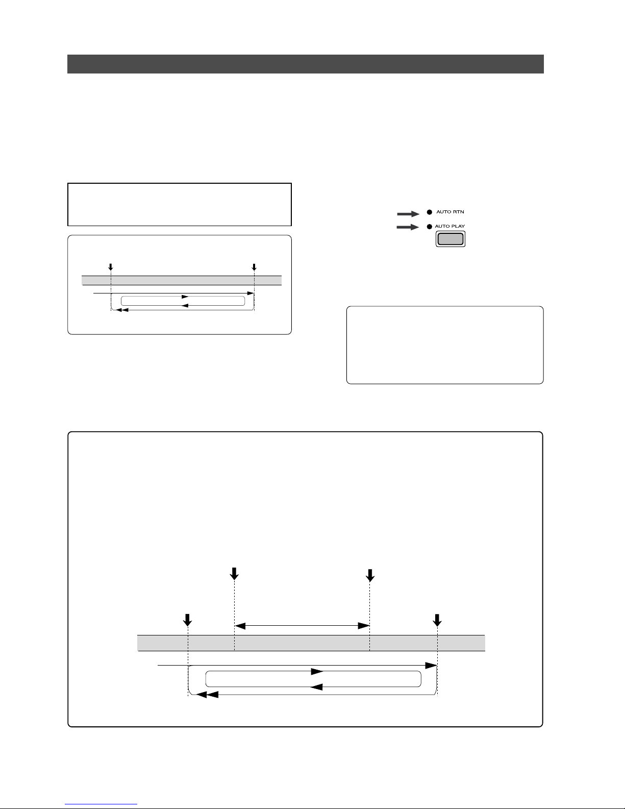
Model D2424LVmkII Reference Manual (Locate Function)
60
AUTO RTN END point
AUTO RTN START point
LOCATE
PLAYBACK
START
PLAYBACK
AUTO RTN END point
AUTO RTN START point
PLAYBACK
START
AUTO PUNCH IN point
AUTO PUNCH OUT point
Rehearsal range
PLAYBACK
LOCATE
<Hint!>
You can make repeated Auto Punch In/Out rehearsal much easier and quicker by using the Auto Repeat
function.
Set the AUTO RTN START point prior to the AUTO PUNCH IN point, and set the AUTO RTN END point
after the AUTO PUNCH OUT point. The recorder will repeat the operation automatically so you can
concentrate on your rehearsal. Cancel Auto Repeat mode before you record a take.
The recorder will play this range repeatedly for rehearsal, which makes it easy for you to check the
recording level and practice your performance.
Auto Repeat function
The Auto Repeat function allows the recorder to repeat playback up to the AUTO RTN END point,
automatically locate the AUTO RTN START point, then play up to the AUTO RTN END point until
you cancel the function by pressing the STOP button. To enable this function, both AUTO PLAY
mode and AUTO RTN mode should be turned on, and the AUTO RTN START point and the AUTO
RTN END point should already be set.
Using this function will facilitate the Auto Punch In/Out and Manual Punch In/Out rehearsal. See
“Hint!” after the following section.
<Operation of the Auto Repeat mode.>
(1) Store the A UTO RTN ST AR T and AUTO RTN END
points.
Refer to the chapter “Storing a Locate Point (Edit
Point)” on page “54” for information on storing the
desired points in the [AUTO R TN START] key and the
[AUTO RTN END] key.
(3) Start playback a little before the A UT O R TN START
point.
The recorder operates as shown in the diagram,
and stops at the AUTO RTN START point.
• You can set a preroll time in the “Preroll Time?”
menu in SETUP mode so that the recorder will
start playback preroll time before the locate
point. You can set the preroll time from 0 to
10 seconds. Refer to the chapter “Changing
the Initial Settings (SETUP Mode)” on page
“113.”
(2) Press the [AUTO RTN/AUTO PLAY] key to turn on
the [PLAY RTN], [AUTO PLAY] LEDs.
<Note>
If the "
Chain Play?
" menu in the SETUP mode is set other
than "
Off
," ON/OFF of AUTO REPEAT cannot be executed.
Page 61
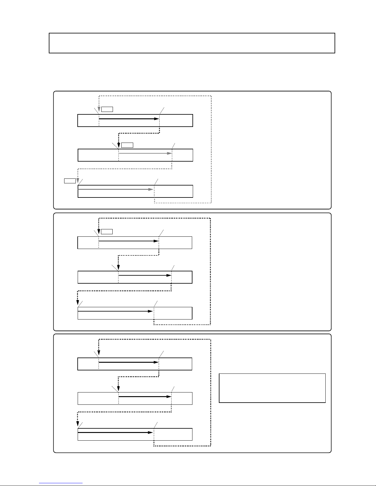
Model D2424LVmkII Reference Manual (Chain Play function)
61
Chain Play function
“Chain play” functions to playback, in any order, the tunes recorded on a multiple number of
programs. There are three modes of chain play and each operates as shown below.
Before executing these modes, “AUTO RTN START point” and “AUTO RTN END point” must be set for
each program. For details, please read the explanations starting from the next page.
<Pause mode>
In the pause mode, as shown in the
example on the left, upon reaching the
“END point” at playback of program 02,
the recorder automatically stops at the
“START point” of program 05 which is to
be played back next.
If chain play is executed again at the
stopped point, it will stop again at the
next program 10 “ST ART point.”
<Auto Play mode>
In the auto play mode, as shown in the
example on the left, upon reaching the
“END point” of program 02 started in
playback, the recorder will automatically
playback in setup order between the
“START points - END points,” and, at the
moment playback is finished at the “END
point” of the last program 01, stops at the
“ST AR T point” of the first program.
<Repeat mode>
In the repeat mode, playback is repeated
until the above auto play mode is
canceled.
<Note>:
If power is switched off and then
switched on again while set to the Repeat
mode, playback will automatically start from
the first program.
AUTO RTN START point
Playback
Playback
Playback
AUTO RTN START point
AUTO RTN START point
AUTO RTN END point
AUTO RTN END point
AUTO RTN END point
PGM 02
PGM 05
PGM 01
STOP
AUTO RTN START point
Playback
Playback
Playback
AUTO RTN START point
AUTO RTN START point
AUTO RTN END point
AUTO RTN END point
AUTO RTN END point
PGM 02
PGM 05
PGM 01
AUTO RTN START point
Playback
Playback
Playback
AUTO RTN START point
AUTO RTN START point
AUTO RTN END point
AUTO RTN END point
AUTO RTN END point
PGM 02
PGM 05
PGM 01
STOP
STOP
STOP
Page 62
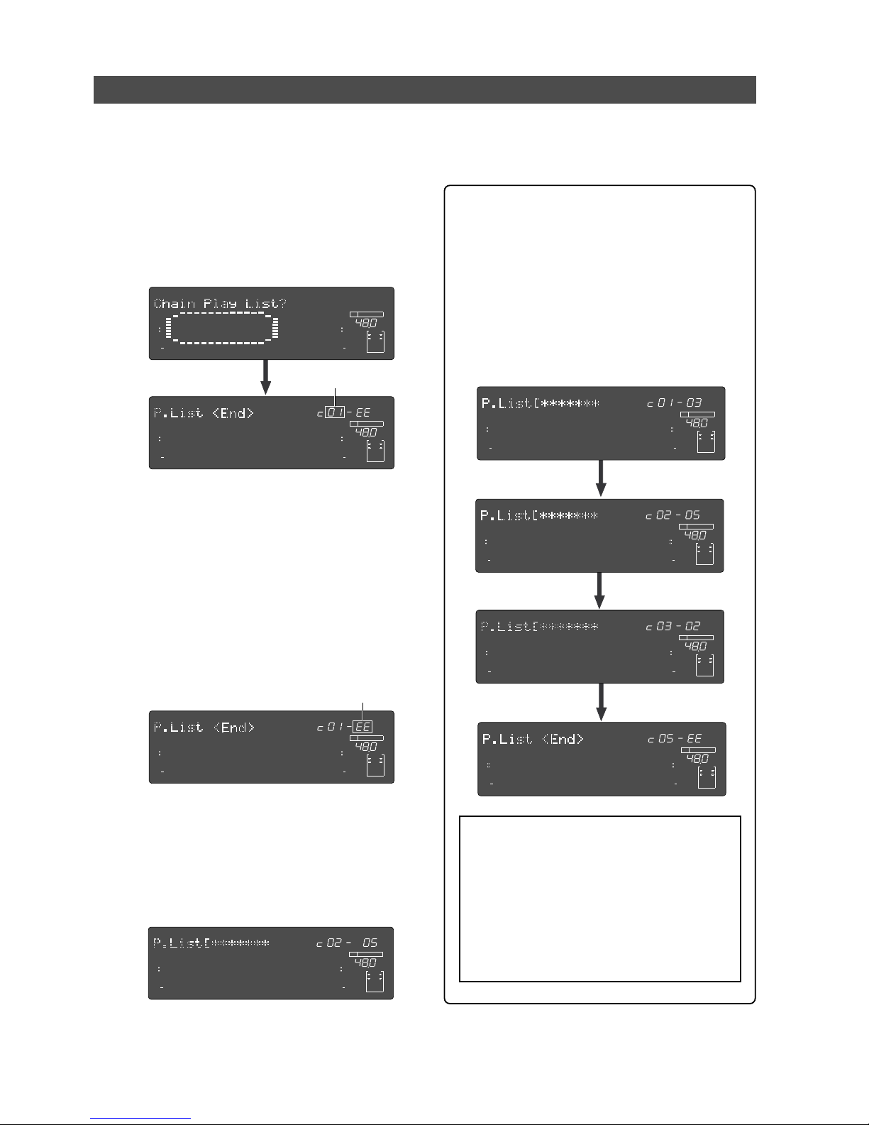
Model D2424LVmkII Reference Manual (Chain Play function)
62
Setup of the Chain Play List
The chain play list is setup via the “Chain Play List?” menu in the SETUP mode.
The following procedure is based on the assumption that a multiple number of programs are in the
current drive and that a tune is recorded in each program.
(1) Enter the SETUP mode by pressing the [SETUP]
key while the D2424LVmkII is in the stop mode.
(2) Use the Jog dial to display the “Chain Play List?,”
and then press the [EXECUTE/YES] key.
The display will change to setup of the play list.
Flashing
This display indicates the initial setting in which
no chain list is setup (“EE” means “invalid.”).
The chain play number can be set in the currently
blinking section (left) and numbers “01” through
“99” can be input via the Jog dial.
Also, the flashing section can be moved from the
left “01” to the right “EE” by pressing the [EXECUTE/
YES] key, and except for “EE,” each program
number currently in the disk can be selected via
the Jog dial.
(3) Input the chain number via the Jog dial and press
the [EXECUTE/YES] key.
The flashing section will move from left to the right
“EE.”
(4) Select the desired program number via the Jog dial
and press the [EXECUTE/YES] key.
The chain number of the selected program will be
set and, the same as in <Step 2>, the left section
will flash.
For example, if it has been set as shown below, the
setting will be for playback of the program 5 tune
in the second order.
Repeat these procedures to set up the chain play
number in the desired program.
<Setup example of the chain play list>
As an example, if the chain play list is set as shown
below, chain play is possible in the order of:
program 3 - program 5 - program 2.
If the chain list is to be ended after program 1, as
shown in the example below, set “EE” at fourth
(“c04”) in the chain list.
By selecting “EE,” the chain play list setting will
be “c01” - “c03,” and beyond “c04” will be invalid.
“EE” can be selected with the Jog dial while the
right program number is flashing.
<Notes>
• In order to execute chain play, “
AUTO RTN
ST AR T point
” and “
AUT O RTN END point
” must
be setup in each program to be played back.
Refer to previous page “
54
” for how to register
memory points.
• If the chain play list is edited even once, the
Chain Play Mode will be set “
OFF
.”
In such case, after setup of the chain play list,
reset the Chain Play Mode to “
ON
” .
∞
42
OL
0
30
24
18
12
9
6
3
kHz
24
FS
BIT
SETUP
24
∞
42
OL
0
30
24
18
12
9
6
3
232221201918
17
16151413121110
98765
4
3
2
1
CLOCK
INT
∞
42
OL
0
30
24
18
12
9
6
3
kHz
24
FS
BIT
SETUP
PGM
24
∞
42
OL
0
30
24
18
12
9
6
3
232221201918
17
16151413121110
98765
4
3
2
1
CLOCK
INT
Flashing
∞
42
OL
0
30
24
18
12
9
6
3
kHz
24
FS
BIT
SETUP
24
∞
42
OL
0
30
24
18
12
9
6
3
232221201918
17
16151413121110
98765
4
3
2
1
CLOCK
INT
∞
42
OL
0
30
24
18
12
9
6
3
kHz
24
FS
BIT
SETUP
24
∞
42
OL
0
30
24
18
12
9
6
3
232221201918
17
16151413121110
98765
4
3
2
1
CLOCK
INT
∞
42
OL
0
30
24
18
12
9
6
3
kHz
24
FS
BIT
SETUP
24
∞
42
OL
0
30
24
18
12
9
6
3
232221201918
17
16151413121110
98765
4
3
2
1
CLOCK
INT
∞
42
OL
0
30
24
18
12
9
6
3
kHz
24
FS
BIT
SETUP
24
∞
42
OL
0
30
24
18
12
9
6
3
232221201918
17
16151413121110
98765
4
3
2
1
CLOCK
INT
∞
42
OL
0
30
24
18
12
9
6
3
kHz
24
FS
BIT
SETUP
24
∞
42
OL
0
30
24
18
12
9
6
3
232221201918
17
16151413121110
98765
4
3
2
1
CLOCK
INT
∞
42
OL
0
30
24
18
12
9
6
3
kHz
24
FS
BIT
SETUP
24
∞
42
OL
0
30
24
18
12
9
6
3
232221201918
17
16151413121110
98765
4
3
2
1
CLOCK
INT
Page 63
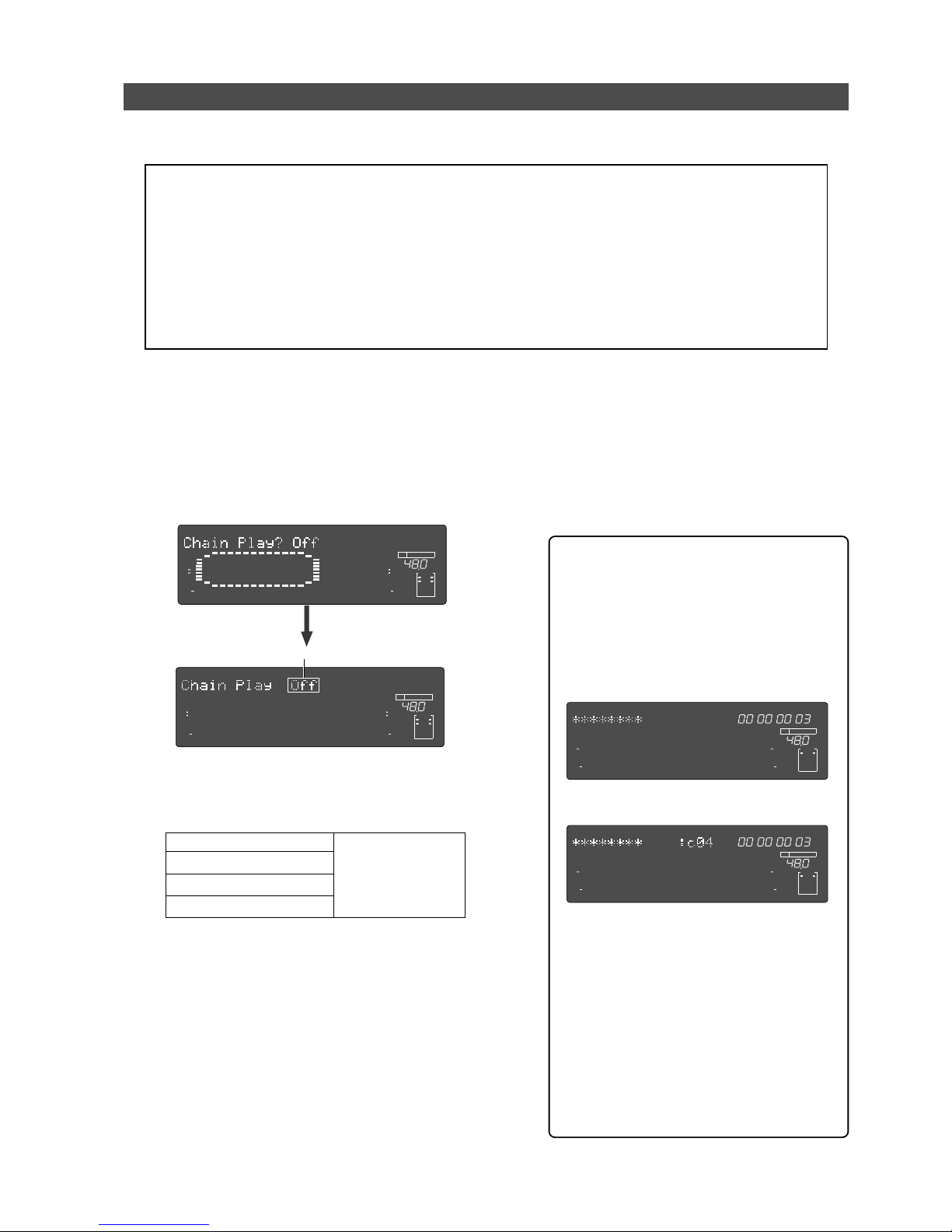
Model D2424LVmkII Reference Manual (Chain Play function)
63
Setup of the Chain Play Mode
<Important>:
Be sure the Chain Play List is set up correctly before setting the chain play mode. Each
setting of the chain play mode except “
Off
,” will not function if the previously mentioned “
Chain play
list
” is not set up correctly beforehand. If the mode is executed while set up of with an incorrect list,
after displaying “
Illegal P.List!
,” the D2424LVmkII will automatically go to the previously mentioned
“
Chain Play List?
” menu.
<Note>:
The chain play mode setting will be held even though power is switched off, and if power is
switched when the D2424LVmkII is set to pause mode, the recorder will automatically execute chain
play. If chain play is no longer required, reset to “
Off”
the “
Chain Play?
” menu after ending chain
play.
(1) Press the [SETUP] key while the D2424LVmkII is
in the stop mode to switch to the SETUP display.
(2) Display the “Chain Play MD?” menu via the Jog
dial and then press the [EXECUTE/YES] key.
The recorder will change to the display for setting
up of the chain play mode and the present setup
mode will flash (In the initial setup, “Off” will flash).
(3) Select the desired mode via the Jog dial.
When the Jog dial is rotated, modes other than the
currently shown “Off” listed below can be selected.
“Off”
“Pause” (P ause mode)
“Auto P” (Auto play mode)
“Rpt” (P epeat mode)
Refer to previous page
61 on the function of
each mode.
If the D2424LVmkII is played back after this, functions of the mode selected will be executed from
the first program in the chain list.
Normally, in chain play as explained above, execution starts from the first program on the chain list
but any program of your choice can be specified
and chain play executed from that program.
For details, refer to “Specify the program and execute
chain play”.
∞
42
OL
0
30
24
18
12
9
6
3
kHz
24
FS
BIT
SETUP
24
∞
42
OL
0
30
24
18
12
9
6
3
232221201918
17
16151413121110
98765
4
3
2
1
CLOCK
INT
∞
42
OL
0
30
24
18
12
9
6
3
kHz
24
FS
BIT
SETUP
24
∞
42
OL
0
30
24
18
12
9
6
3
232221201918
17
16151413121110
98765
4
3
2
1
CLOCK
INT
Flashing
(4) Press the [EXECUTE/YES] key after selecting the
mode.
The recorder will exit from the SETUP mode after
setup is completed.
In this step, if it was completed in the setup other
than the “Off” mode, the D2424LVmkII will
automatically locate to the “AUTO R TN START point”
of the first program in the previously setup “Chain
list” and stop.
If it was completed after setup to “Off,” the
D2424LVmkII will return to the first display of the
program prior to entering the SETUP mode.).
<The “Current” display after setup>
If the “Chain Play?” menu is set to other
than “Off” (“Pause,” “Auto P” or “Rpt”), then
exit from the SETUP mode, the current display will change as shown in example below and, the display will be different from
when it is set to “Off.”
<When “Chain Play?” is set to “Off. ”>
<When “Chain Play?” is set to other than “Off.”>
The above is an example showing that program 03 (P03) activated by the ABS time
base, is set at fourth in the chain list.
As shown here, when the chain list is correctly setup and the “Chain Play?” menu
set to other than “Off,” in which order (For
example, “c04”) of the chain list had the
presently active program been setup, will
be indicated. Should it be changed to another time base, the chain list number will
be indicated in the same manner.
FSM
∞
42
OL
0
30
24
18
12
9
6
3
kHz
24
FS
BIT
PGM
24
∞
42
OL
0
30
24
18
12
9
6
3
ABS
232221201918
17
16151413121110
98765
4
3
2
1
CLOCK
INT
FSM
∞
42
OL
0
30
24
18
12
9
6
3
kHz
24
FS
BIT
PGM
24
∞
42
OL
0
30
24
18
12
9
6
3
ABS
232221201918
17
16151413121110
98765
4
3
2
1
CLOCK
INT
Upon setup of the previous “Chain Play List,” select the desired mode in the “Chain Play MD?” (Setup
of the chain play mode) menu in the same SETUP mode.
Page 64
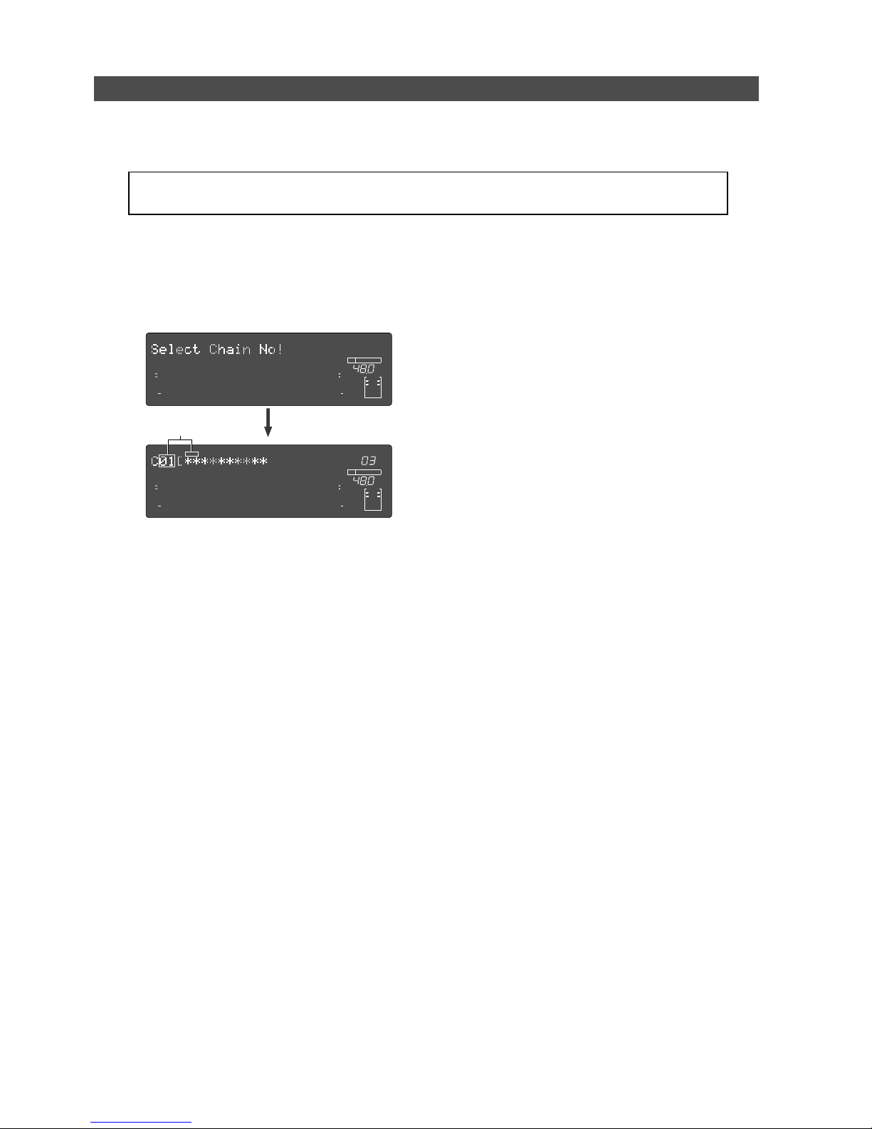
Model D2424LVmkII Reference Manual (Chain Play function)
64
Specify the Program and Execute Chain Play
(1) Press the [PGM SEL] key while the D2424LVmkII
is in the stop mode.
After “Select Chain No!,” is displayed, the first
number in the present chain play list will flash and
the program, and its title, will be displayed.
(2) Select the desired program with the Jog dial and
press the [EXECUTE/YES] key.
The sequence number currently set in the chain
list can be selected by rotating the Jog dial.
The program/title in selected order will be
simultaneously displayed. After selection, when the
[EXECUTE/YES] key is pressed, the D2424LVmkII will
locate to the “AUTO R TN START point” of the selected
program.
(3) Start playback by pressing the [PLAY] button.
Chain play will be execute in compliance to the
currently set “Chain Play MD?” mode.
∞
42
OL
0
30
24
18
12
9
6
3
kHz
24
FS
BIT
24
∞
42
OL
0
30
24
18
12
9
6
3
232221201918
17
16151413121110
98765
4
3
2
1
CLOCK
INT
∞
42
OL
0
30
24
18
12
9
6
3
kHz
24
FS
BIT
PGM
24
∞
42
OL
0
30
24
18
12
9
6
3
SURE?
232221201918
17
16151413121110
98765
4
3
2
1
CLOCK
INT
<Note>:
You cannot record or edit in the chain play mode. It will only play back the program set in the
chain play list.
Flashing
Specify at random a program set in the chain play list and execute chain play from the program
specified. This operation can be executed only when the “Chain Play?” menu is set in other than
“Off.”
Page 65
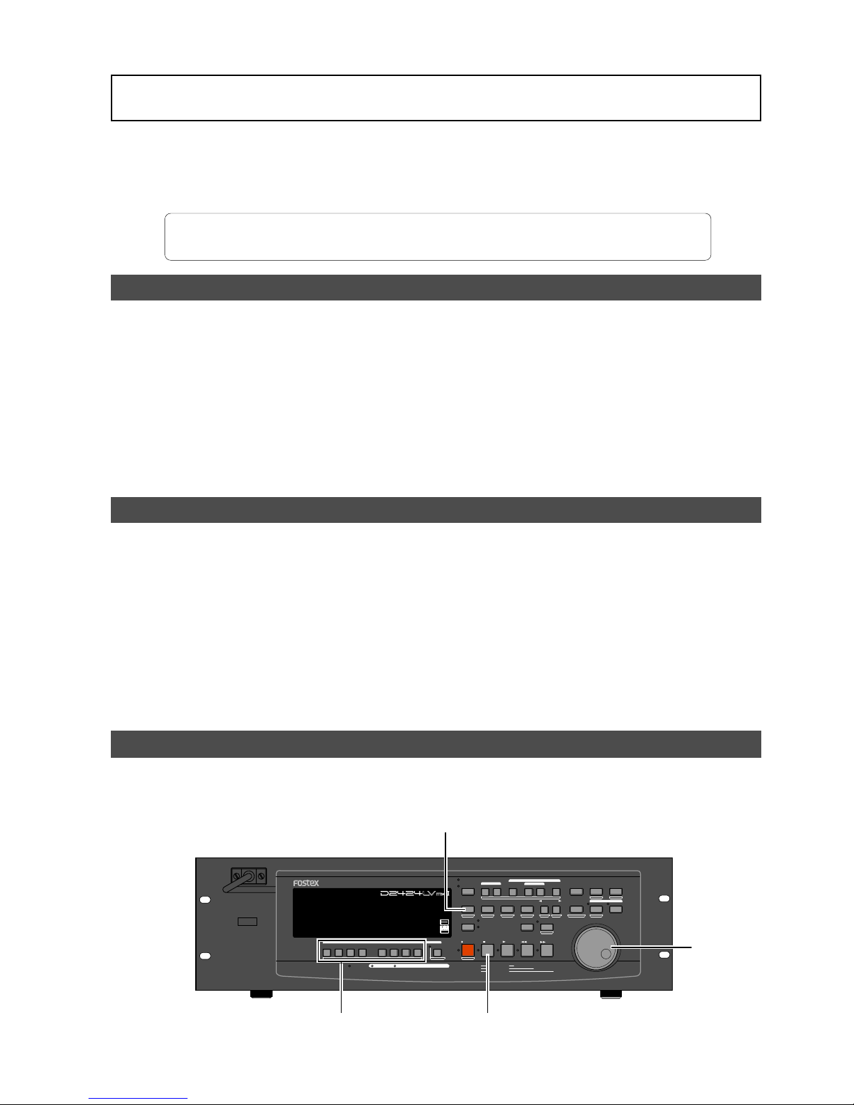
65
Model D2424LVmkII Reference Manual (Cue & Review Function)
Cue & Review Function
This chapter explains how to use the “Cue & Review” function with the [REWIND] button, the
[F FWD] button, and the Shuttle dial, and also explains “Digital Scrubbing” with the envelope function.
During Cue/Review and Digital Scrubbing you will hear the sound recorded on the disk, which
makes it easy for you to swiftly locate the desired point without failure while listening to the
sounds.
The prerequisite of the following operation is that the time base is ABS, however, the operation can
be executed in any time base. To execute this function with a non-ABS time base there is a need to
priory switch over to the desired time base.
Cue & Review function using the [REWIND] and [F FWD] buttons
You may cue & review the audio data at five-times speed while the recorder is playing.
(1) Press the [PLAY] button to play the audio data.
(2) Press the [F FWD] button during playback.
This cues in the forward direction at five-times
speed. The PLAY LED and F FWD LED lights up while
cuing is taking place.
(3) Adjust the monitor sound of the track to monitor
on the mixer .
(4) Press the [PLAY] b utton again to restore the original
play back speed.
(5) Press the [REWIND] button instead of the [F FWD]
button.
This cues in the rewind direction at five-times speed.
The PLAY LED and REWIND LED lights up while
cuing is taking place.
(6) Press the [PLAY] button to restore the original
playback speed.
Cue & Review function using the Shuttle dial
You can use the Shuttle dial for +1~-7 times or -1~-8 times
(1) Press the [PLAY] button to start playback.
(2) T urn the Shuttle dial clockwise during playback.
The forward direction cue speed variates from +1~
-7 times speed depending on the degree (angle) of
turning the dial. PLAY LED flashes and F FWD LED
lights up during the cue process.
(3) Adjust the monitor sound of the track to monitor
on the mixer .
(4) Let go of the Shuttle dial to return to normal play
speed.
(5) Similarly, turn the Shuttle dial counterclockwise
during playback.
The rewind direction review speed variates from
-1~ -8 times speed depending on the degree (angle)
of turning the dial. PLAY LED flashes and REWIND
LED lights up during the review process.
(6) Let go of the Shuttle dial to return to normal play
speed.
Digital scrubbing using the envelope function
You may perform digital scrubbing using the “Envelope Function” of the recorder while the recorder
is stopped. The envelope function allows digital scrubbing for each track recorded. The display
will show the envelope indication of the track selected.
POWER
HOLD
RECORD
STOP
PLAY
REW
F FWD
ALL INPUT
ALL READY
LOCATE REC END
VARI PITCH
PUNCH
LOCATE
REHEARSAL
TAKE
RECALL
STORE
EXIT/NO
EXECUTE/YES
PGM SEL
NEXT
PREV
UNDO/REDO
PREVIEW
EDIT SETUP
AUTO RTN
OUTIN
AUTO PLAY
START
OUTIN
END
17-24
ACCESS
9-16
1/9/17
2/10/18
3/11/19
4/12/20 5/13/21 6/14/22 7/15/23
8/16/24
FOOT SW
LOCATE ABS 0
CLIPBOARD PLAY
AUTO
TRACK SHIFT
SHIFT
DISP SEL
CHARACTER
TIME BASE SEL
P.EDIT
EJECT
ENVELOPE
CHASE
TC READY TC GEN M.UNDO
TRACK SHIFT
PREV TC
NEXT TC
RECORD TRACK
CLIPBOARD
AUTO PUNCH
AUTO RTN
LOCATE MEMORY
24bit
96kHz
OPTICAL
24TRACK DIGITAL RECORDER
1, 4
5
2
1
Page 66
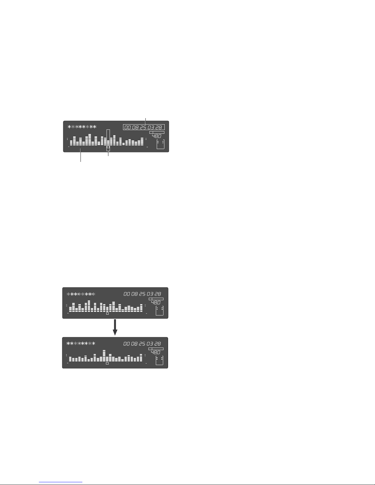
66
Model D2424LVmkII Reference Manual (Cue & Review Function)
Playback point (time)
Playback point
Track indication
(5) Press the [STOP] button to stop the envelope
function.
Doing so will turn OFF the envelope function.
The recorder will return to the time base indication
prior to turning the envelope function ON.
(1) While the recorder section is stopped, depress the
[SHIFT] key and then press the [RECORD TRACK]
select key of the desired record track.
This turns ON the envelope function.
The envelope indication of the selected track will
appear on the display.
The following example shows the indication of track
4 envelope, after [RECORD TRACK] select key
[4/12/20] is pressed. At this time the recorder is in
the STILL status (scrub mode is in still status) and
the REWIND LED and F FWD lights up.
(2) You can use the Jog dial to digitally scrub the
performance of the track selected.
The envelope of the performance recorded on the
track variates in real-time. During forward direction
scrub the F FWD LED lights up, and during rewind
direction scrub the REWIND LED lights up.
(3) Adjust the monitor sound of the selected track so
that it can be monitored on the mixer.
(4) Press the [RECORD TRACK] select key of the
desired record track to select another track.
“Please Wait!” will briefly appear and then go to the
envelope indication of the selected track.
The following example shows the case when the
indication is switched from track 4 to track 12.
FSMH
∞
42
OL
0
30
24
18
12
9
6
3
kHz
FS
CLOCK
BIT
SF
INT
24
∞
42
OL
0
30
24
18
12
9
6
3
ABS
4
FSMH
∞
42
OL
0
30
24
18
12
9
6
3
kHz
FS
CLOCK
BIT
SF
INT
24
∞
42
OL
0
30
24
18
12
9
6
3
ABS
4
FSMH
∞
42
OL
0
30
24
18
12
9
6
3
kHz
FS
CLOCK
BIT
SF
INT
24
∞
42
OL
0
30
24
18
12
9
6
3
ABS
12
Page 67
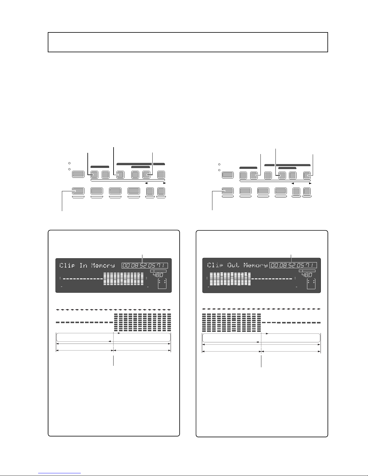
Model D2424LVmkII Reference Manual (Preview Function)
67
Preview Function
1 sec. (mute playback)
1 sec. (normal playback)
The sound rises at the memory point.
SHIFT key
[CLIPBOARD] IN key
[AUTO R TN START] key
[AUTO PUNCH OUT] ke y
[CLIPBOARD OUT] key
[AUTO RTN END] k e y
[AUTO PUNCH IN] key
1 sec. (normal playback)
1 sec. (mute playbac k)
The sound falls at the memory point.
Approx. 2sec.
Memory data
Memory data
SHIFT key
Approx. 2sec.
The preview function enables you to repeatedly audition the rise (fade in) or the fall (fade out)
of the sound data at a locate point (edit point) that is stored in the [AUTO PUNCH IN/OUT], [AUTO
RTN START/END], or [CLIPBOARD IN/OUT] key. This is also called “point rehearsal.”
With this function, you can check the locate points in real-time. You can also use this function to
fine-tune the position of the locate points while previewing the sound. This function is effective
only when the recorder is stopped.
• Previewing the rise of the sound (fade in)
While holding down the [SHIFT] key, press the [AUTO RTN
START] key, the [AUTO PUNCH OUT] key, or [CLIPBOARD
IN] key.
• Previewing the fall of the sound (fade out)
While holding down the [SHIFT] key, press the [AUTO END
START] key, the [AUTO PUNCH IN] key, or the [CLIPBOARD
OUT] key.
<Display indication during the Preview operation>
The recorder repeats playback the “rise sound” at
the locate point (edit point). As shown in the
diagram, one-second of data prior to the locate
point is muted during playback.
The mute is off (fade in) at the locate point and
the sound is played back for one second.
The recorder will repeat this operation until you
quit the Preview function.
<Display indication during the Preview operation>
The recorder repeats playback of the “fall sound”
at the locate point (edit point).
As shown in the diagram, one-second of data prior
to the locate point is played back, then muted (fade
out) at the locate point. The muted playback
continues for one second.
The recorder will repeat this operation until you
quit the Preview function.
During operation, the meter display will light up from left to right.
During operation, the meter display will light up from left to right.
NEXT
PREV
UNDO/REDO
PREVIEW
EDIT SETUP
AUTO RTN
OUTIN
AUTO PLAY
START
OUTIN
END
SHIFT
CHARACTER
TC READY TC GEN M.UNDO
PREV TC
NEXT TC
CLIPBOARD
AUTO PUNCH
AUTO RTN
NEXT
PREV
UNDO/REDO
PREVIEW
EDIT SETUP
AUTO RTN
OUTIN
AUTO PLAY
START
OUTIN
END
SHIFT
CHARACTER
TC READY TC GEN M.UNDO
PREV TC
NEXT TC
CLIPBOARD
AUTO PUNCH
AUTO RTN
FSMH
∞
42
OL
0
30
24
18
12
9
6
3
kHz
FS
CLOCK
BIT
SF
INT
1
24
∞
42
OL
0
30
24
18
12
9
6
3
LOCATE
234
5
6
78
91011 12 131415 16
17
1819202122 23
24
FSMH
∞
42
OL
0
30
24
18
12
9
6
3
kHz
FS
CLOCK
BIT
SF
INT
1
24
∞
42
OL
0
30
24
18
12
9
6
3
LOCATE
234
5
6
78
91011 12 131415 16
17
1819202122 23
24
Page 68
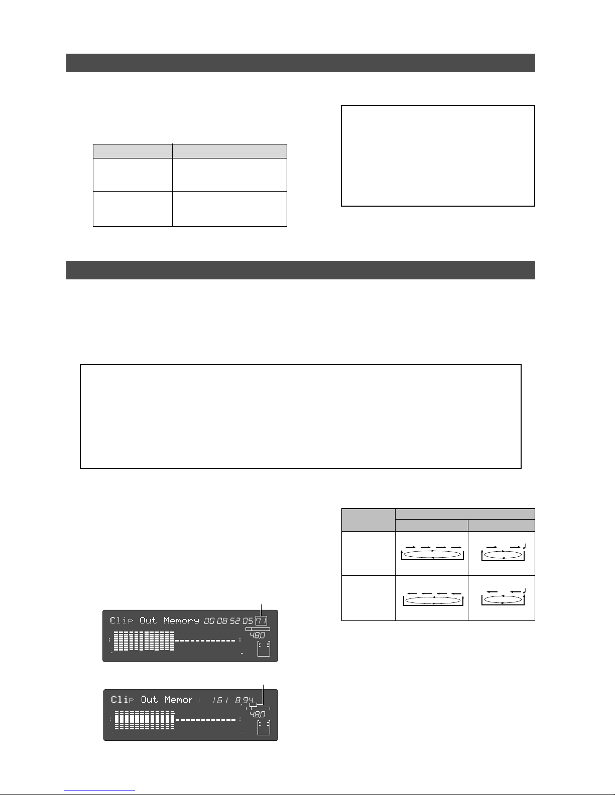
Model D2424LVmkII Reference Manual (Preview Function)
68
[AUTO PUNCH IN] ke y
[AUTO R TN END] ke y
[CLIPBOARD OUT] key
[AUTO PUNCH OUT] ke y
[AUTO R TN START] key
[CLIPBOARD IN] key
OperationMemory key
Time base
ABS or MTC BAR/BEAT/CLK
Flashing
Shuttle dial
(clockwise)
Flashing
Shuttle dial
(counter clockwise)
Executing the Preview function
(1) Press the desired memory key while holding
down the [SHIFT] key when the recorder is
stopped.
Pressing the desired memory key will enable you
to preview the sound at the locate point (edit point)
stored in the corresponding memory key.
The recorder plays the fall (fade
out) of the sound at the locate
point stored in the keys.
The recorder plays the fall (fade
in) of the sound at the locate
point stored in the keys.
(2) Adjust the monitor sound of the selected track
so that it can be monitored on the mixer.
<Note>:
If data stored in each memory key is
in the initial state, all memory keys will be in
ABS time 00H 00M 00S. In other words, the
program head value is in the memory. Should
fade out preview be executed in this condition,
the “
V oid Data!
” message and memory data “
00H
00M 00S
” will alternately flash in the display as
a warning. However, for fade in preview, this
will function as the memory data “
00H 00M 00S
”
point.
(3) Press the [STOP] button or the [EXIT/NO] key.
Trimming the sound while previewing
You can trim the position of the locate point (edit point) using the Jog dial while you preview the
sound. At this time, you can also adjust the size of the trimming steps (the amount of offset
controlled by the Jog dial).
Trimming allows you to fine-tune the position of the locate point stored in the memory keys
while previewing the sound. Use this function to change the Auto Punch In/Out points, the start
point of Copy & Paste and Move & Paste, and the start and end points of the Erase function.
<Notes>
• You can audition the result of trimming during the next preview. That is, if you trim the position while
previewing the sound for the first time, you can check the result when you preview the sound next time.
• If the locate point is shifted outside the range of the preview playback as a result of trimming, “
Void Data!
”
and the locate point indication appear alternately. In this case, you cannot use the Preview function. Trim
the position again so that it will be within the playback range.
• When Auto Punch mode is turned on and you trim the Auto Punch In or Auto Punch Out point while
previewing the sound with “
Void Data!
” indicated on the display, Auto Punch mode will be cancelled.
(4) Trim the position at the selected unit (digit).
(5) Press the [STOP] button or the [EXIT/NO] key.
The trimmed locate point (edit point) data will be
stored in the corresponding memory key.
(1) Start previewing the sound by follo wing the steps
described on the previous page.
(2) Use the Jog dial to trim the position.
When previewing starts, the unit of Jog trimming
flashes on the screen.
For example, value of SF (sub-frame) flashes if ABS
Time Base or MTC Time Base is selected.
CLK (clock) flashes if BAR/BEAT/CLK is selected.
The flashing value also indicates the position you
can trim.
(3) To change the unit of trimming, turn the Shuttle
dial.
FSMH
∞
42
OL
0
30
24
18
12
9
6
3
kHz
FS
CLOCK
BIT
SF
INT
1
24
∞
42
OL
0
30
24
18
12
9
6
3
LOCATE
234
5
6
78
91011 12 131415 16
17
1819202122 23
24
∞
42
OL
0
30
24
18
12
9
6
3
kHz
FS
CLOCK
BIT
INT
1
24
∞
42
OL
0
30
24
18
12
9
6
3
CLKBAR
LOCATE
234
5
6
78
91011 12 131415 16
17
1819202122 23
24
SF
H
MS
F
SF
H
MS
F
CLK
BAR
CLK
BAR
Page 69
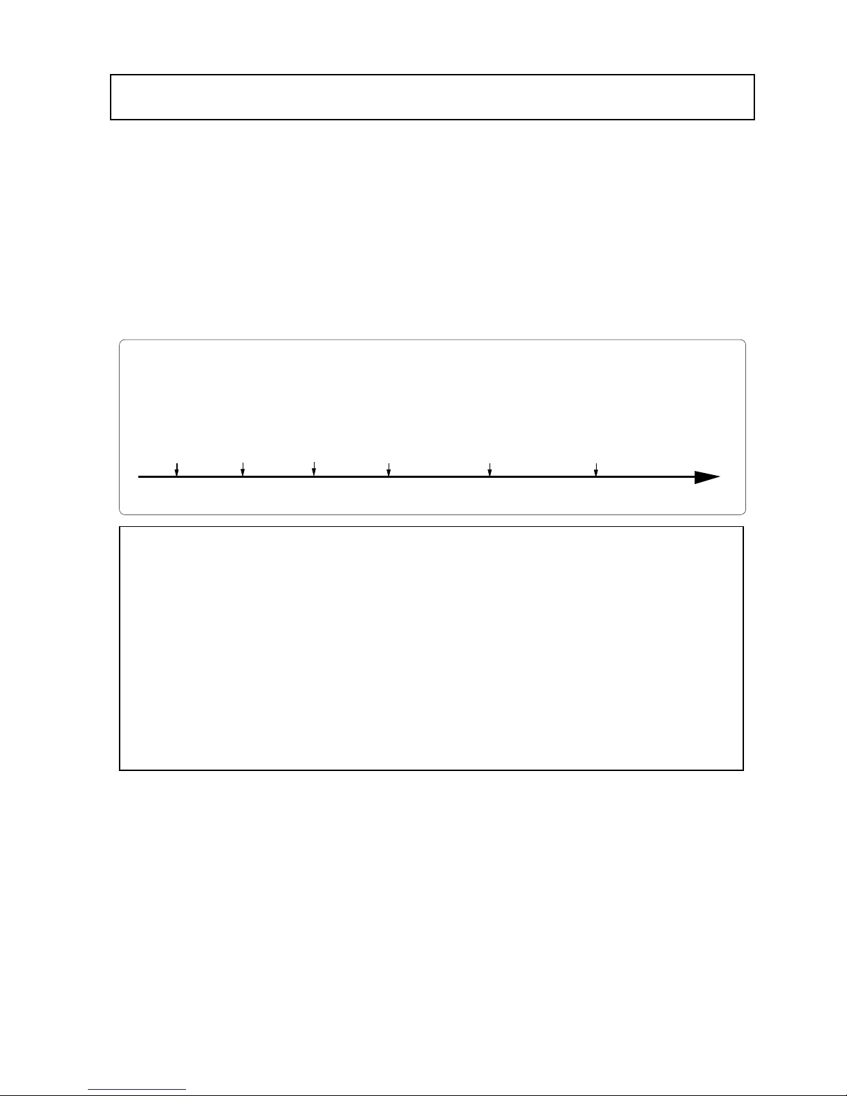
Model D2424LVmkII Reference Manual (Multiple Undo Function)
69
Multiple Undo Function
Completion
data and time
of Take 1
Time axis
To undo recordings or edits, you can use the Multiple Undo (Time Jump) function (explained in this
section) as well as the Single Undo/Redo function (explained in the Quick Operation Guide and the
“Punch in/out” and “Track editing” sections of this manual).
You can use the Multiple Undo (Time Jump) function only for a current drive disk that was formatted
with the Multiple Undo turned on. (See page 31 for more information on the format operation.)
The Single Undo/Redo function enables you to undo and redo the current take of recording or edit
(Punch in/out, Copy & Paste, Move & Paste, Erase). However, if you record a new take, you will no
longer be able to apply the Undo/Redo function to the previous take.
On the other hand, the Multiple Undo (Time Jump) function can be applied to all takes made after the
current drive disk is formatted. To undo a take, select the date and time (at which you finish
making the corresponding take) of the edit based on the internal clock.
When you finish recording or editing a take on a current drive disk that was formatted with the
Multiple Undo function turned on, that take will get the time stamp of the internal clock (e.g.: [10:50.37
11.Dec?]). Therefore, you can always recall the desired take. This is quite different from the Single
Undo/Redo function.
Completion
data and time
of Take 2
Completion
data and time
of Take 3
Completion
data and time
of Take 4
Completion
data and time
of Take 5
Completion
data and time
of Take 6
<Notes regarding the Multiple Undo operation>
• The time stamp of each take references to the internal clock of the recorder.
Therefore, after formatting the current drive disk, be sure to set the internal clock correctly. Refer to the
Quick Operation Guide for more information on how to set the internal clock.
• Recording (or editing) more takes will consume more disk space on a current drive disk that was formatted
with the Multiple Undo function turned on. This is because more disk space is required to enable the
Undo function for any take. Therefore, such a current drive disk with a smaller capacity may not have
enough disk space to perform the Multiple Undo function. In this case, performing the disk optimization
in Setup mode may increase the free space available for the Undo function. (For more information, see the
“
Helpful Tips
” on page 70.)
• If you use the Multiple Undo function, you cannot use the Single Undo/Redo function.
• If you try to use the Multiple Undo function on a current drive disk that was formatted with the Multiple
Undo function turned off, the recorder displays “
V oid!
” and ignores your operation.
Page 70
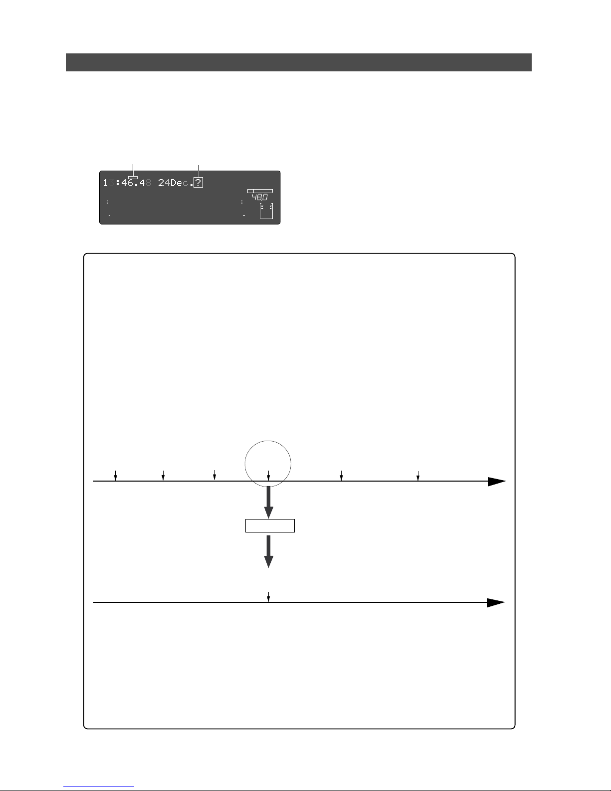
Model D2424LVmkII Reference Manual (Multiple Undo Function)
70
Multiple Undo for Take 4
Optimize
FlashingFlashing
Using the Multiple Undo function
(1) While the recorder is stopped, press and hold down
the [SHIFT] key and press the [UNDO/REDO] key.
The recorder displays the date and time of a take
(as shown below), and “?” and “SURE ?” flash.
To select the date and time for another take, turn
the Jog dial.
(2) Use the Jog dial or the [NEXT] key and [PREV] key
to select the desired date and time, and press the
[EXECUTE/YES] key.
The recorder displays “Multiple Undo” momentarily,
performs the Undo function, and recalls the time
base indication that was shown before the function
was performed. “COMPLETED!” lights up on the
screen.
(3) Press the [EXIT/NO] key or the [STOP] button.
“COMPLETED!” turns off.
Completion
data and time
of Take 4
Time axis
<Helpful Tips>
To increase the free space on the disk available for the Multiple Undo function, optimize the
current drive disk using the “Disk Optimize?” menu in Setup mode. However, remember that if
you optimize a current drive disk that recorded several takes, only the most recent take will
remain and other takes will be erased. If you wish to keep other takes, follow the procedure
below, then optimize the disk.
<Keeping only one take>
• First, apply the Multiple Undo function to the take you wish to keep, then optimize the disk.
For example, if six takes exist on the disk, as shown below, and you wish to keep only Take 4,
apply the Multiple Undo function to Take 4.
As shown on the second time axis, Take 4 moves up to the most recent position. Now, if you
optimize the disk, all takes but Take 4 will be erased.
<Keeping multiple takes>
• Apply the Multiple Undo to the desired takes and copy the Program.
For example, if you wish to keep Take 2 and Take 4, follow the procedure described above to
apply the Multiple Undo function to Take 2, then create a copy of the Program. (The Program
copy will have only Take 2 available for the Multiple Undo function.)
In the same way, apply the Multiple Undo function to Take 4 this time, then create another copy
of the Program. In this way, you can create copies of the Programs that contain the desired takes.
∞
42
OL
0
30
24
18
12
9
6
3
kHz
24
FS
BIT
24
∞
42
OL
0
30
24
18
12
9
6
3
SURE?
232221201918
17
16151413121110
98765
4
3
2
1
CLOCK
INT
Completion
data and time
of Take 1
Time axis
Completion
data and time
of Take 2
Completion
data and time
of Take 3
Completion
data and time
of Take 4
Completion
data and time
of Take 5
Completion
data and time
of Take 6
Page 71
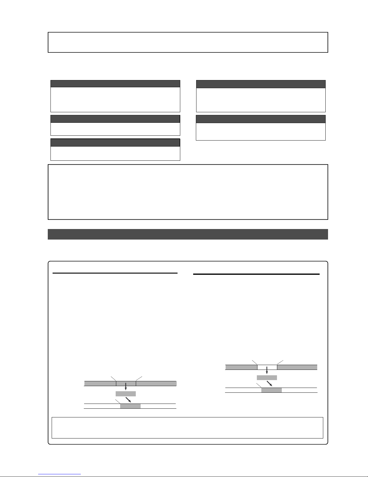
Model D2424LVmkII Reference Manual (Editing Tracks)
71
Editing Tracks
The recorder features speedy, nonlinear, nondestructive editing of independent audio tracks because
it uses a 3.5 inch E-IDE hard disk. The following four editing functions allow “Editing of Independent
Audio T racks.”
Copy & Paste
You can copy a specific range of data from a specific
track and paste it to the same or a different track.
Copy & Paste is possible in the presently active program
or also in a different program.
Move & Paste
You can move a specific range of data from a specific
track and paste it to the same or a different track.
Move & Paste
You can erase a specific range of data from a specific
track or all tracks.
Track Exchange
Between tracks 1-56, exchanging is possible in mono
track units or group track units (Stereo pair 2 tracks
or 8 tracks).
<Note>:
Although Copy & Paste can be executed in a different program, all other editing work can only be
done within the currently active program. Consequently, in order to edit the active program, the desired
program should be selected before starting to edit. In general, don’t change a program until you finish
editing except to Copy & Paste to a different program.
If editing is started while in another program, you could accidentally lose data.
Copy & Paste, Move & Paste, and Erase with the exception of track exchange and editing the track name, is
possible only for data recorded on the real track. If data stored in the additional track is to be edited, move
it temporarily to a real track, and then edit it.
Copy & Paste and Mo ve & Paste
Copy & Paste and Move & Paste might seem like the same function. However, they are different, as
shown in the diagram. Remember this difference when you start using these functions.
• Copy & Paste
Using the Copy & Paste function enables you to copy
a specific range of data from a specific track to the
clipboard as shown below (this is called “Copy Clip”
operation on the unit), then paste the data at a
specific point in a specific track.
The number of copy source tracks and the number
of destination tracks are the same. That is, if you
copy mono track data, you can paste it to a mono
track. If you copy adjacent odd/even tracks (e.g.,
track 1 and track 2), you can paste it to adjacent
odd/even tracks. After paste is executed, data on
the clipboard will remain intact and as can be
repeatedly pasted, as well as to other programs.
• Move & Paste
Move & Paste is almost the same as Copy & Paste.
As shown in the figure, it allows you to move a
specific range of data from a specific track to the
clipboard (this is called “Move Clip” on the unit), and
paste it to a destination track.
The difference from Copy & Paste is that the data on
the source track and the clipboard will be erased
when you paste the data to the destination. That is,
you cannot paste the moved data repeatedly.
Unlike Copy & Paste, this cannot be executed between
programs.
As shown in the drawing, points for copy or move are called the CLIPBOARD IN point for the copy (or move) starting
point, and CLIPBOARD OUT point for the ending point, and the paste starting point is called the AUTO PUNCH IN
point.
CLIPBOARD IN point
CLIPBOARD OUT point
Copy clip
Copy source track
Paste destination track
Paste
AUTO PUNCH IN point
CLIPBOARD IN point
CLIPBOARD OUT point
Move clip
Move source track
Paste destination track
Paste
AUTO PUNCH IN point
Editing the track name
Any type of track name can be registered and edited
for each channel.
Page 72
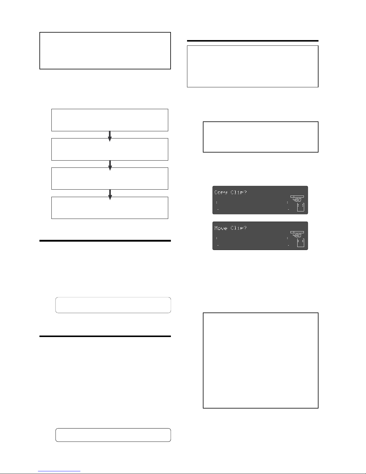
Model D2424LVmkII Reference Manual (Editing Tracks)
72
<Notes>
• The data on the clipboard will be replaced by new
data each time you execute the COPY or MOVE.
• If pasted data overlaps the source data, the content
of the source data will be altered.
Perform Copy & Paste and Move & Paste in the
following order. The explanation here is on Copy &
Paste or Move & Paste methods in the currently active
program. For Copy & Paste between programs, read page
“71”.
Store the copy (or move) start point (CLIPBOARD IN
point), end point (CLIPBOARD OUT point), and the
paste start point (AUTO PUNCH IN point).
Check the stored edit points using the Preview function
and make adjustments if necessary .
Specify the copy (or move) source tr ack, and copy (or
move) the data to the clipboard.
Specify the destination track and the number of times
for the paste operation (repeated paste), and ex ecute
the paste operation.
• Storing the edit points
(1) Refer to the “Storing and editing the locate points
to the memory keys” section for information on
storing the copy (or move) start and end points,
and the paste start point.
Store the copy (or move) start point to the
[CLIPBOARD IN] key, the end point to the
[CLIPBOARD OUT] key, and store the paste start
point to the [AUTO PUNCH IN] key.
• See “Storing and editing the locate points to
the memory keys” on page “
54
.”
• Checking and adjusting the edit points
After you store the edit points, you can check them
on the display by pressing the corresponding keys.
You may also adjust the points. This section explains
how to preview and fine-tune the edit points using
the Preview function.
(1) While the recorder section is stopped, press and
hold down the [SHIFT] key and press the memory
key for which y ou wish to c hec k the edit point.
You can preview “fade in” at the CLIPBOARD IN point,
“fade out” at the CLIPBOARD OUT point, and “fade
out” at AUTO PUNCH IN point.
(2) T rim the edit point while previewing.
• Refer to “Preview Function” on page “67” for
more information.
• Executing Copy (or Move)
(1) Press the RECORD TRACK select key of the copy
(or move) source track to set it READY .
Select from mono tracks or adjacent odd-even tracks
(1-2, 3-4, 5-6 etc.).
(2) Press the [EDIT] key repeatedly until “Copy Clip?”
(or “Mo ve Clip?”) flashes on the display.
Select “Copy Clip?” to execute Copy & Paste.
Select “Move Clip?” to execute Move & Paste.
<Note>:
If you select non-adjacent tracks, such
as track 1 and 3, or tracks 1 and 4, the copied
(or moved) data will be pasted back to the
copy (or move) source tracks.
(3) Press the [EXECUTE/YES] key.
The copy (or move) operation will complete
immediately. The display briefly indicates
“COMPLETED !”, then flashes the “Copy Paste ?” (or
“Move Paste ?”) message.
The recorder enters standby mode for the paste
operation. The indicates (small square) of the
selected [RECORD TRACK] select keys continue to
flash.
<Notes>
• Pressing the
[EXECUTE/YES]
key without
selecting track in Step 1 will cause the
display to indicate an alarm message “
Select
TRK !”
. Select a track, then press the
[EXECUTE/YES]
key.
• If an Output point has been specified before
the In point (the In point value is the same
or large than the Out point value), the
display will show the error message “
V oid In
Point!
” or “
V oid Out P oint!
” and the return to
the previous screen. In this case, set the
correct In/Out points and try again to copy
(or move) the data.
Now the sound data to be pasted has been copied
(or moved) to the clipboard, you can check the data
on the clipboard by following the steps below.
If there is no problem with the data, you can proceed
to the paste operation.
1.
2.
3.
4.
∞
42
OL
0
30
24
18
12
9
6
3
kHz
24
FS
BIT
24
∞
42
OL
0
30
24
18
12
9
6
3
232221201918
17
16151413121110
98765
4
3
2
1
CLOCK
INT
∞
42
OL
0
30
24
18
12
9
6
3
kHz
24
FS
BIT
24
∞
42
OL
0
30
24
18
12
9
6
3
232221201918
17
16151413121110
98765
4
3
2
1
CLOCK
INT
<Note>
: You can carry out the copy (or move) func-
tion only when the “
Chain Play?
” menu in the Setup
mode is set to “
Off
.” If you press the
[EDIT]
key
when this menu is not set to “
Off
,” “
V oid Chain Play!
”
is shown and the operation is ignored. If “
Void Chain
Play!
” is shown, set the “
Chain Play?
” menu to “
Off
.”
Page 73
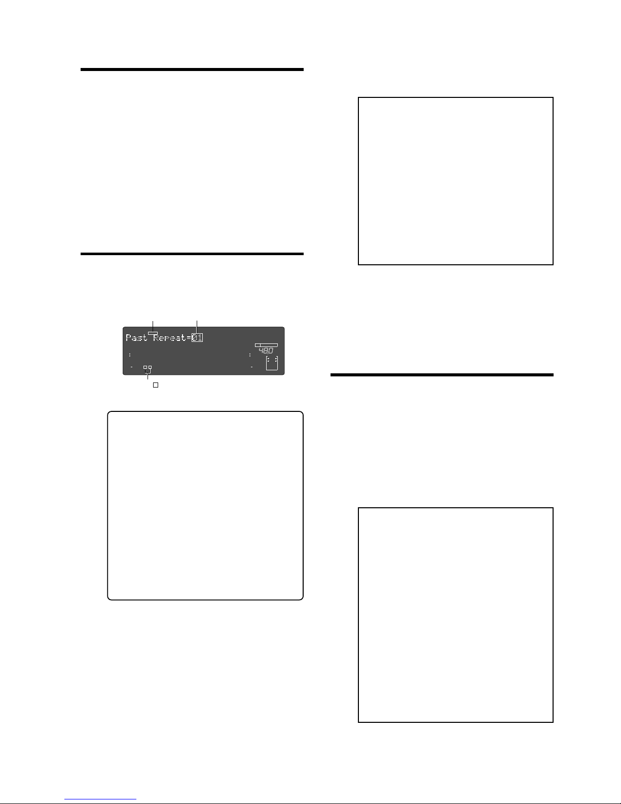
Model D2424LVmkII Reference Manual (Editing Tracks)
73
Flashing
• Executing Paste
(4) Press the [EXECUTE/YES] key again.
The display indication enables you set the number
of the paste operations. The number and “SURE?”
flash. At this time, the flashing [RECORD TRACK]
indicator becomes continuously lit.
(5) Select a destination track to paste data.
(8) Press the [EXIT/NO] key or the [STOP] button.
The recorder exits edit mode and displays the
previous Time Base indication.
(9) Turn off the [RECORD TRA CK] select ke y of the
copy (or move) source track.
<Note>:
If you try to execute the paste
operation by pressing the
[EXECUTE/YES]
key
when the disk has insufficient free space, “
Over
!”
appears on the display and edit mode is
cancelled. In this case, you need to delete
unnecessary data or programs.
• Refer to the following section, “Erase,”
“Deleting a Program,” or “Duplicating a
Program.”
• Refer to page “
76
” for more information on
erasing.
• Refer to page “
40
” for more information on
deleting a program.
• Refer to page “
39
” for more information on
duplicating a program.
• Single Undo/Redo Paste
You can single undo or redo a Copy & Paste
and Move & Paste operation.
• To restore the data that existed prior to the paste
operation, press the [UNDO/REDO] key.
• To restore the pasted data after y ou undo the paste
operation, press the [UNDO/REDO] key again.
When you press the [UNDO/REDO] key, the recorder
will undo or redo the operation immediately, and
display “Undo !” or “Redo !” and “COMPLETED !”.
T rack display ( ) of the item to be copied (or moved) will change to lit.
∞
42
OL
0
30
24
18
12
9
6
3
kHz
24
FS
BIT
24
∞
42
OL
0
30
24
18
12
9
6
3
SURE?
232221201918
17
16151413121110
98765
4
3
2
1
CLOCK
INT
Flashing
• Checking the clipboard data
• Hold down the [STOP] b utton and press the [PLAY]
button.
The recorder indicates whether the sound data on
the clipboard is a copied data or moved data (“Copy
Clip” or “Move Clip”) and plays the data (this is called
“clipboard playback”). Monitor the playback sound
through the mixer channels that correspond to the
copied (or moved) tracks. During clipboard
playback, the indicates of the [RECORD TRACK]
select key for the copied (or moved) track will flash.
• Press the [EDIT] key again to get ready for the paste
operation.
“Copy Paste?” or “Move Paste? ” flashes on the
display.
(6) Turn the Jog dial to enter the number of repeats
(Repeat = **).
You can enter up to 99.
However, this is automatically limited by the
available recording source on the disk.
That is, if the disk has enough free space, you can
set up to 99 repeats. If the disk has only a small
amount of free space, the Jog dial allows you to set
a lower number of repeats.
(7) Press the [EXECUTE/YES] key.
“Copy Paste” (or “Move Paste ”) flashes and the
duration of the pasted data appears as a negative
number on the display.
• If paste is to be done on the same track, it is
not necessary to select the track.
• Changing the destination track for paste is
permissible to a mono track or adjacent two
tracks in odd and even numbers (1-2, 3-4, 5-6,
etc.) only when the copy (or move) data is on
the clip board.
For this procedure, if the [RECORD TRACK]
select key of the track to be changed is pressed,
and an objective track for pasting can be
selected.
• If a multiple number of tracks (1-3, 5-8, etc.)
other than those above had been copied (or
moved), paste can be done only to the same
track as that of the copy (or move) originating
track. The track cannot be selected even though
the [RECORD TRACK] select key is pressed.
This number will count down as the paste operation
proceeds. When the paste operation is complete,
the flashing “Copy Paste” (or “Move Paste”) lights
up continuously, and “COMPLETED !” is displayed.
<Note>:
This function only works when this
recorder is in the stop mode.
<Note>:
If you perform one of the following
operations after you use the Copy & Paste or
Move and Paste operation, the Undo/Redo
function will no longer be effective.
1. If a new recording has been made.
2. When a new editing job is executed (such
as Copy & Paste, Move & Paste, Erase).
3. While in the AUTO PUNCH ON mode,
when the AUTO PUNCH IN point is
passed in the PLAY (or RECORD) mode.
4. If the power was switched off.
5. If program select was executed.
6. When multiple undo is executed.
Page 74
Model D2424LVmkII Reference Manual (Editing Tracks)
74
• Copy & Paste between programs
Copy & Paste between programs can be performed
using the procedures below in the same manner as
in the previous “Copy & Paste in the same program.”
1.
2.
3.
4.
5.
6.
7.
8.
Store the copy (or move) start point (CLIPBOARD IN
point), end point (CLIPBOARD OUT point), and the
paste start point (AUTO PUNCH IN point).
Check the stored edit points using the Preview function
and make adjustments if necessary.
Specify the track to be copied and copy it in the clipboard
(Copy Clip).
Switch to program for pasting using the program select
function.
Register the copy starting point (AUTO PUNCH IN point)
in the switched program.
Check the registered editing point with the “Preview
function” and if necessary, correct the editing point.
In the same way as before, enter the editing mode by
pressing the [EDIT] key . “Copy P aste?” will be displayed
after pressing the [EDIT] key.
Next, specify the track and amount to be pasted and
execute paste.
• Checking the clipboard data
Data copied to the clipboard can be confirmed even
after switching the program by the above procedure.
For example, when a specific data in Program 1 is
copied to the clipboard and then switched to
Program 2 in which it is to be pasted, as mentioned
before, if the [PLA Y] button is pressed while pressing
on the [STOP] button, you can listen to data copied
in Program 1 (clipboard play).
During clipboard play, “P01” will appear in the
display to indicate that copy data in Program 1 is
being played back.
<Notes>
• Only copy/paste can be executed between
different programs. Move/paste cannot be
executed between different programs.
• Do not copy/paste between programs with
different FS such as copy/paste FS=48kHz
program data to an FS=44.1kHz program.
Sound data cannot be guaranteed if copy/paste
had been executed between programs with
different FS.
Page 75
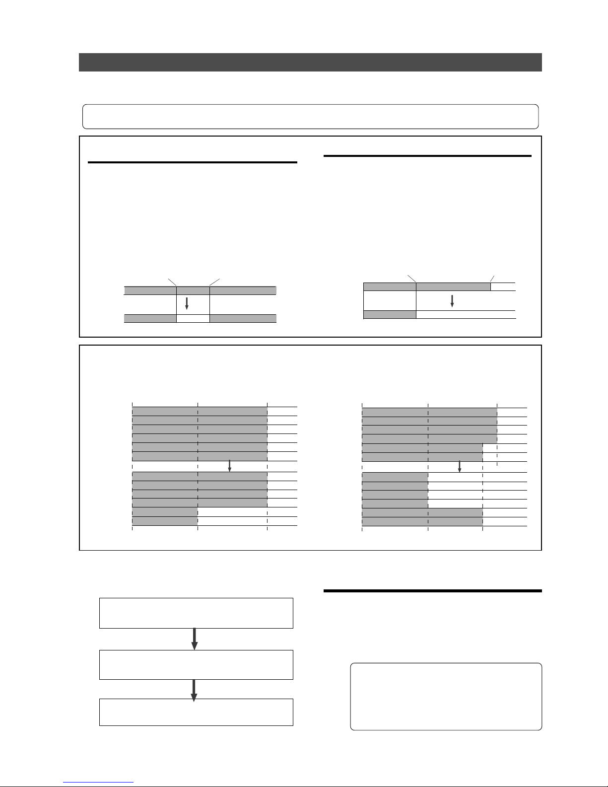
Model D2424LVmkII Reference Manual (Editing Tracks)
75
AUTO PUNCH IN point
AUTO PUNCH OUT point
Erase
Any real track
AUTO PUNCH IN point
AUTO PUNCH OUT point
(REC END)
Erase
REC END
ABS 0
Silence
Silence
AUTO PUNCH IN point
Erase
Erase
ABS 0
AUTO PUNCH OUT point
(REC END)
Trk 6
Trk 5
Trk 4
Trk 3
Trk 2
Trk 1
Trk 6
Trk 5
Trk 4
Trk 3
Trk 2
Trk 1
REC END
ABS 0
AUTO PUNCH IN point
Erase
Erase
ABS 0
AUTO PUNCH OUT point
(REC END)
Trk 6
Trk 5
Trk 4
Trk 3
Trk 2
Trk 1
Trk 6
Trk 5
Trk 4
Trk 3
Trk 2
Trk 1
REC END
ABS 0
Erase
Erase
Real tracks
Real tracks
Erase
There are two methods for erasing data. Understand the difference between these methods before
you use the Erase function.
• If multiple Programs are set on the disk, first select the desired Program. Do not select another Program, or select
another sampling rate until you finish the erase operation.
• Erasing a specified part of the data between ABS 0
and REC END:
You may erase a specified part of the data between ABS
0 and REC END (the end point of the recording) in the
currently-selected Program. (The erased part is replaced
with silence.) You can erase data on a mono real track
or multiple real tracks. To erase data on an additional
track, you need to move the data to a real track, then
erase it. As shown below, the REC END point (the end
point of recording) is not affected.
The erased area is replaced with silence. As a result, the
REMAIN time and space will increase. (You will have more
recordable space on the disk.)
• Erasing data from a specified point to REC END:
You may erase all data in the range from a specified
point to REC END in the currently-selected Program. You
can erase data on a mono real track or multiple real
tracks. To erase data on an additional track, you need
to move the data to a real track, then erase it.
When you erase all tracks’ data, the REC END point will
move backward. However, if you erase data on a mono
track or multiple tracks (but not all tracks), the REC
END point may not be affected. (Refer to the note below.)
After the erase operation, the REMAIN time and space
will increase.
<Note>:
If all real tracks contain data as shown below, erasing data on tracks 1 and 2 will not affect the position of
REC END. On the other hand, if all Real tracks contain data as shown below, erasing data on tracks 3 - 6 will move up
REC END to the end point of tracks 1 and 2.
Real tracks
Real tracks
Follow the steps below to erase data:
Store the erase start point (AUTO PUNCH IN point)
and the erase end point (AUT O PUNCH OUT point).
Use the Preview function to check the stored edit points
and adjust them if necessary.
Specify a track to erase and execute the function.
1.
2.
3.
• Storing the edit points
(1) Refer to the “Storing and editing the locate points
to the memory keys” section for information on
storing the erase start and end points.
Store the erase start point to the [AUTO PUNCH IN]
key, and the end point to the [AUTO PUNCH OUT]
key.
• If you wish to erase the data from a specific
point, store the REC END or later point as the
erase end point. Refer to the <Note> for
information on storing the REC END point.
• See “Storing and editing the locate points to
the memory keys” on page “
54
”.
Any real track
Any real track
Any real track
Page 76
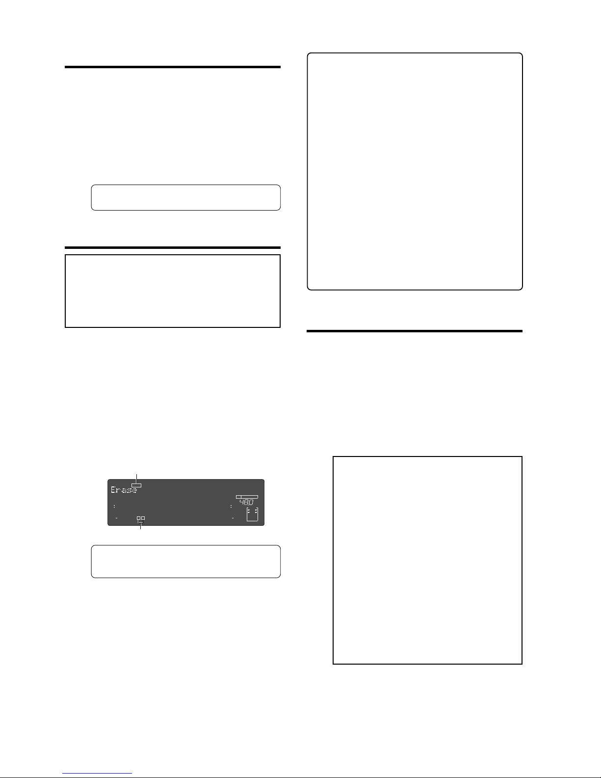
Model D2424LVmkII Reference Manual (Editing Tracks)
76
Flashing
Lit
• Checking and adjusting the edit points
After you store the edit points, you can check them
on the display by pressing the corresponding keys.
You may also adjust the points.
(1) While the recorder section is stopped, press and
hold down the [SHIFT] key and press the memory
key for which y ou wish to c hec k the edit point.
You can preview “fade-out” at the AUTO PUNCH IN
point and “fade-in” at AUTO PUNCH OUT point.
(2) T rim the edit point while previewing.
• Refer to “Preview Function” on page “67” for
more information.
• Executing Erase
(1) Press the [RECORD TRACK] select key to select
the track to erase, to set it READY.
You can select a mono track or multiple tracks
(including all tracks). The selected track indication
flashes.
(2) Press the [EDIT] key repeatedly until “Erase”
flashes on the display.
(3) Press the [EXECUTE/YES] key.
The flashing “Erase” message lights up steadily, and
“SURE?” flashes.
• To cancel the erase operation, press the
[STOP]
button or the
[EXIT/NO]
key while “
SURE ?
”
flashes on the display.
(4) Press the [EXECUTE/YES] key again.
The recorder starts erasing the data and
“Wait Erasing!” flashes. When the erase operation
is completed, “COMPLETED !” lights up.
(5) Press the [STOP] button or the [EXIT/NO] ke y.
The recorder exits edit mode and displays the
previous Time Base indication.
<Check P oints!>
• To erase the data in its entirety from the tracks,
you can also use the Program Delete function to
erase the entire Program.
In either case, you can expand the recordable
area on the disk. Use either one of the erase
operations to erase unnecessary data if the
recorder displays an alarm message indicating
insufficient recordable space for Auto Punch In/
Out, Copy & Paste, or Move & Paste.
• To erase the data in its entirety from ABS 0 - REC
END, it is recommended that erase end point
(AUTO PUNCH OUT point) is stored after the REC
END time to ensure through erase performance.
To do this, move the recorder section location to
the REC END point prior to storing the AUTO
PUNCH OUT point, press the [PLAY] button from
that location, move the ABS time after the REC
END, and store.
The hard disk will not successfully access points
after REC END though play is executed after REC
END, however, this makes it possible to move up
the ABS time.
• Single Undo/Redo Erase
You can single undo or redo the Erase operation.
• To restore the data that e xisted bef ore y ou erased
it, press the [UNDO/REDO] key.
• To restore the data after you undo the Erase
operation, press the [UNDO/REDO] key again.
When you press the [UNDO/REDO] key, the recorder
will undo or redo the operation immediately, and
display “Undo !” or “Redo !” and “COMPLETED !”.
∞
42
OL
0
30
24
18
12
9
6
3
kHz
24
FS
BIT
24
∞
42
OL
0
30
24
18
12
9
6
3
SURE?
232221201918
17
16151413121110
98765
4
3
2
1
CLOCK
INT
<Note>
: You can carry out the erase function only
when the “
Chain Play?
” menu in the Setup mode is
set to “
Off
.” If you press the
[EDIT]
key when this
menu is not set to “
Off
,” “
V oid Chain Pla y!
” is shown
and the operation is ignored. If “
V oid Chain Play!
” is
shown, set the “
Chain Play?
” menu to “
Off
.”
<Note>:
This function only works when this
recorder is in the stop mode.
<Note>:
If you perform one of the following
operations after you use the Copy & Paste or
Move and Paste operation, the Undo/Redo
function will no longer be effective.
1. If a new recording has been made.
2. When a new editing job is executed (such
as Copy & Paste, Move & Paste, Erase).
3. While in the AUTO PUNCH ON mode,
when the AUTO PUNCH IN point is
passed in the PLAY (or RECORD) mode.
4. If the power was switched off.
5. If program select was executed.
6. When multiple undo is executed.
Page 77
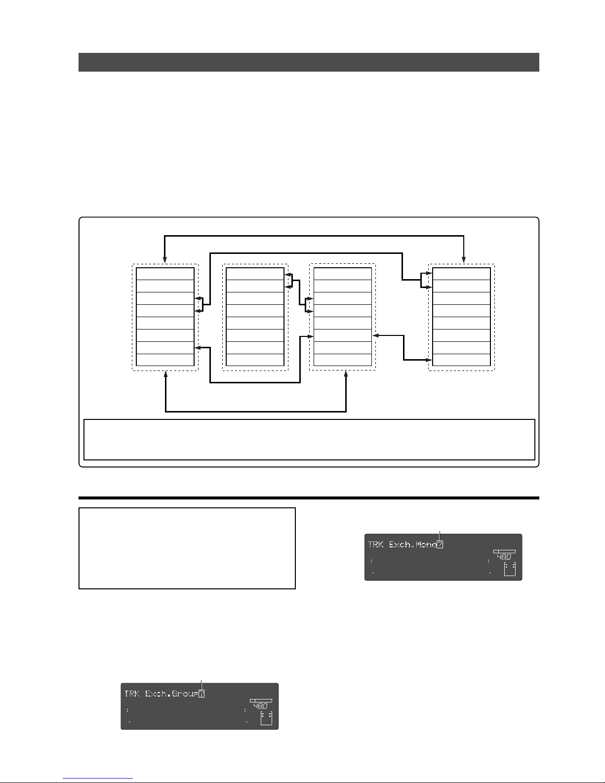
Model D2424LVmkII Reference Manual (Editing Tracks)
77
Flashing
T rac k Exc hange
"Track exchange" is the function that exchanges tracks -- all real tracks and all additional tracks--
currently in the programs, in mono track units or in multiple track (Stereo pair 2 tracks; 8 track
units) units. In other words, exchanging tracks in any combination, as shown below, means that
data recorded on those tracks will be relocated. This function enables effective use of tracks. Not
only will it be possible to make exchanges between real tracks but, by dumping a real track to a
blank additional track, another blank real track is created for future recording.
However, since data in this additional track cannot be directly played back in real time, if the data
need to be played back or edited, it must be moved to a real track.
Also, as explained in the previous "Erase," “T rac k Exchange” is necessary when checking REC END in
the additional track.
• Execution of T rac k Exchange
Track 1
Track 2
Track 3
Track 4
Track 5
Track 6
Track 7
Track 8
Track 9
Track 10
Track 11
Track 12
Track 13
Track 14
Track 15
Track 16
Track 17
Track 18
Track 19
Track 20
Track 21
Track 22
Track 23
Track 24
Track 49
Track 50
Track 51
Track 52
Track 53
Track 54
Track 55
Track 56
.........................
∞
42
OL
0
30
24
18
12
9
6
3
kHz
24
FS
BIT
24
∞
42
OL
0
30
24
18
12
9
6
3
232221201918
17
16151413121110
98765
4
3
2
1
CLOCK
INT
∞
42
OL
0
30
24
18
12
9
6
3
kHz
24
FS
BIT
24
∞
42
OL
0
30
24
18
12
9
6
3
232221201918
17
16151413121110
98765
4
3
2
1
CLOCK
INT
Exchange in 8 track units
Exchange in 2 track (stereo pair) units
Exchange in mono track units
Exchange in 8 track units
(1) In the stop mode, press the [EDIT] key to display
"TRK Exch.Mono?" or "TRK Exch.Group?."
Select "TRK Exch.Group?" to exchange tracks in 2
track (stereo pair)/8 track units, and
"TRK Exch.Mono?" to exchange in mono track units.
• Exchanging in group units
• Exchanging in mono units
(2) After either is displayed, press the [EXECUTE/YES]
key .
The display will change to selecting the tracks for
exchanged. To actually select the tracks, please refer
to the next page.
Flashing
<Note>:
In the “
Format conversion of the additional track
” menu of the SETUP mode, the range of tracks that can be
exchanged will be 1-24 in the current drive in which the “
V2 (56)
” format was converted to “
V1 (24)
” format. For
details on the “Format conversion of the additional track” menu, refer to the SETUP mode on page “
132
.”
<Note>:
You can carry out the track exchange func-
tion only when the “
Chain Play?
” menu in the Setup
mode is set to “
Off
.” If you press the
[EDIT]
key when
this menu is not set to “
Off
,” “
Void Chain Play!
” is
shown and the operation is ignored.
If “
Void Chain Play!
” is shown, set the “
Chain Play?
”
menu to “
Off
.”
Page 78
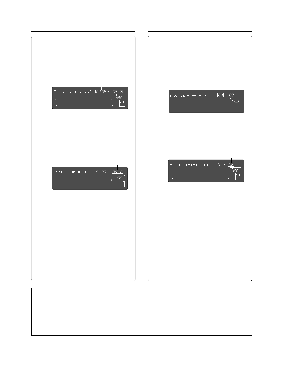
Model D2424LVmkII Reference Manual (Editing Tracks)
78
∞
42
OL
0
30
24
18
12
9
6
3
kHz
24
FS
BIT
24
∞
42
OL
0
30
24
18
12
9
6
3
232221201918
17
16151413121110
98765
4
3
2
1
CLOCK
INT
∞
42
OL
0
30
24
18
12
9
6
3
kHz
24
FS
BIT
24
∞
42
OL
0
30
24
18
12
9
6
3
232221201918
17
16151413121110
98765
4
3
2
1
CLOCK
INT
∞
42
OL
0
30
24
18
12
9
6
3
kHz
24
FS
BIT
24
∞
42
OL
0
30
24
18
12
9
6
3
232221201918
17
16151413121110
98765
4
3
2
1
CLOCK
INT
∞
42
OL
0
30
24
18
12
9
6
3
kHz
24
FS
BIT
24
∞
42
OL
0
30
24
18
12
9
6
3
232221201918
17
16151413121110
98765
4
3
2
1
CLOCK
INT
• Exchanging in group track units
(1) By pressing the [EXECUTE/YES] key after “TRK
Exch. Group?” is displayed, the displa y will
change as shown below.
This display is indicating that, at present, tracks
1-8 and 9-16 can be exchanged.
"*****" is indicating the track name of the
flashing track left two digits (In this example Name of track 01).
(2) If the Jog dial is rotated while "01 08" is
flashing, the 8 track unit n umber s ("09 16,"
"17 24," "25 32," "33 40," "41 48," "49 56") or
pair track unit numbers ("01 02," "03 04"... ....
"55 56") will be alternately displayed.
(3) After selecting the left side track, press the
[NEXT] key to move to the flashing right side.
(4) Display the desired track by rotating the Jog
dial in the same manner as Step 2.
If the flashing display is to be moved from right
to left, either press the [REV] key or rotate the
Shuttle dial.
(5) After selecting the left right tracks, press the
[EXECUTE/YES] key.
Track exchange is executed and simultaneous
with completion, "COMPLETED!" is displayed.
The D2424LVmkII will then return to the
display prior to entering the edit mode.
Regardless as to whether "Exch.01 08-09 16" or
"Exch.09 16-01 08" is input, there will be no
difference in the fact that tracks 1-8 and tracks
9- 16 have been exchanged.
• Exchange in mono track units
(1) Upon display of the previously mentioned "TRK
Exch.Mono?," then pressing the
[EXECUTE/YES] key , the displa y will change as
shown below.
This display indicates that, at present, tracks 1
and 2 can be exchanged.
"*****" is indicating the track name of the
flashing track. In this case, the name of track
01.
(2) If the Jog dial is rotated when "01" is flashing,
the mono track unit numbers ("01"-"56") will
be alternately displayed.
(3) After selecting the left side track, mo ve to the
right side flashing by pressing the [NEXT] key.
(4) The same as in Step 2, display the desired track
by rotating the Jog dial.
Press the [REV] key or rotate the Shuttle dial to
move the flashing number from right to left.
(5) After selecting the left and right tracks, press
the [EXECUTE/YES] key.
Track exchange is executed and simultaneous
with completion, "COMPLETED!" is displayed
and then returned to the display prior to
entering the edit mode.
Whether "Exch.01-09" or "Exch.09-01" is input,
there will be no difference in the fact that track
1 and track 9 have been exchanged.
<Notes>
• You cannot select the same track for left and right.
If the same track is mistakenly specified, "
Select Err
" will be displayed for an instant and then returned to the
display prior to execution.
• As it stands, data in the additional track cannot be played back or REC END confirmed.
To do this, data must be moved temporarily onto a real track. When saving the data to an external DAT, adat
or the CompactFlash card, data on the additional track will be saved in its original state and, when reloading,
will be reinstalled on the disk the same as prior to saving it.
Flashing
Flashing
Flashing
Flashing
Page 79
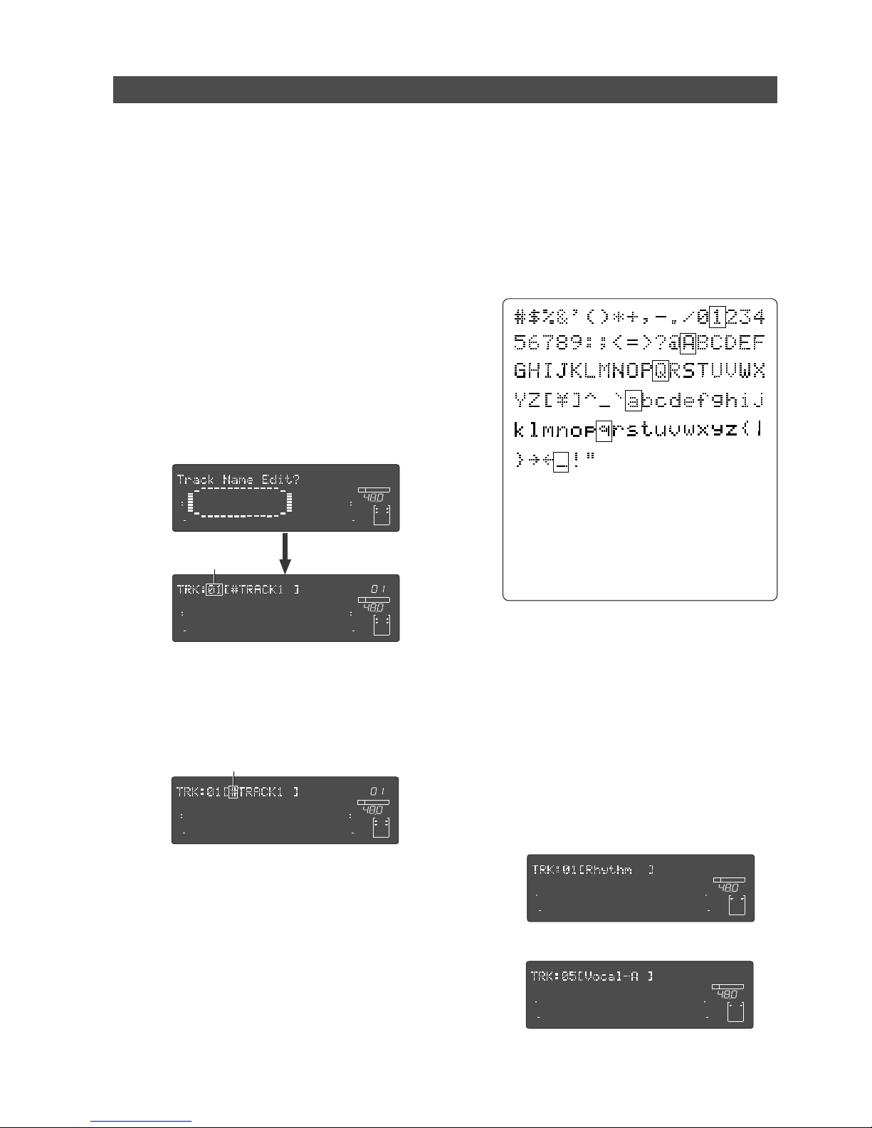
Model D2424LVmkII Reference Manual (Editing Tracks)
79
∞
42
OL
0
30
24
18
12
9
6
3
kHz
24
FS
BIT
SETUP
24
∞
42
OL
0
30
24
18
12
9
6
3
232221201918
17
16151413121110
98765
4
3
2
1
CLOCK
INT
∞
42
OL
0
30
24
18
12
9
6
3
kHz
24
FS
BIT
SETUP
PGM
24
∞
42
OL
0
30
24
18
12
9
6
3
232221201918
17
16151413121110
98765
4
3
2
1
CLOCK
INT
∞
42
OL
0
30
24
18
12
9
6
3
kHz
24
FS
BIT
SETUP
PGM
24
∞
42
OL
0
30
24
18
12
9
6
3
232221201918
17
16151413121110
98765
4
3
2
1
CLOCK
INT
Any type of track name can be registered or edited for each real track/additional track.
In general, after the current drive is formatted, a "Temporary title"("#TRACK 1," etc.) is automati-
cally registered for all tracks.
This temporary title can be changed and registered as you wish using the "Trac k Name Edit?" menu
in the SETUP mode.
For example, to allow checking at a glance, sound sources (guitar, keyboard, vocal...etc.) recorded
on each track, a maximum 8 digit track name can be registered, such as "Guitar" for track 1,
"Keyboard" for track 2, "Vocal" for track 3, and so on.
Registering the Trac k name
(1) Enter the SETUP mode while in the stop mode by
pressing the [SETUP] key.
(2) Select the "Track Name Edit?" display by rotating
the Jog dial, and then press the [EXECUTE/YES]
key.
As shown below, the display will change to
selecting the desired track and the track number
will flash.
In the example below, "01" in "TRK:01" will flash.
(3) Rotate the Jog dial while "01" is flashing to select
the desired track number , and press the
[EXECUTE/YES] key.
The flashing number will move to the left-end digit
to allow input of new letters and symbols.
In example below, "#" will flash.
(4) Numbers and symbols can be input at the selected
(flashing) digit by rotating the Jog dial, and the
flashing digit can be moved with the Shuttle dial.
If the Jog dial is rotated at the edit point, letters/
numbers/symbols listed in the following can be
input.
A maximum of 8 digits can be input for a name.
(5) After input of the desired track name, press the
[EXECUTE/YES] key.
By pressing the [EXECUTE/YES] key, the
D2424LVmkII will change to the track number
selecting display, the same as in Step-2 (Track
number will flash).
(6) If you wish to continue registering track names,
repeat <Step-3> and <Step-4>.
(7) Upon completing registering of the track names,
press the [EXIT/NO] key to exit from the SETUP
mode.
Flashing
Flashing
<Hint>
If the [PREV] key or [NEXT] key is pressed when
inputting letters/symbols/numbers at the edit
point (flashing position), it is possible to jump
to the letters/symbols in the above square
box. This is convenient for quickly selecting
the letters/symbols/numbers to be input.
∞
42
OL
0
30
24
18
12
9
6
3
kHz
24
FS
BIT
SETUP
24
∞
42
OL
0
30
24
18
12
9
6
3
232221201918
17
16151413121110
98765
4
3
2
1
CLOCK
INT
∞
42
OL
0
30
24
18
12
9
6
3
kHz
24
FS
BIT
SETUP
24
∞
42
OL
0
30
24
18
12
9
6
3
232221201918
17
16151413121110
98765
4
3
2
1
CLOCK
INT
* Example: Trac k 1 -> “Rhythm”
* Example: Trac k 5-> “Vocal-A”
Page 80
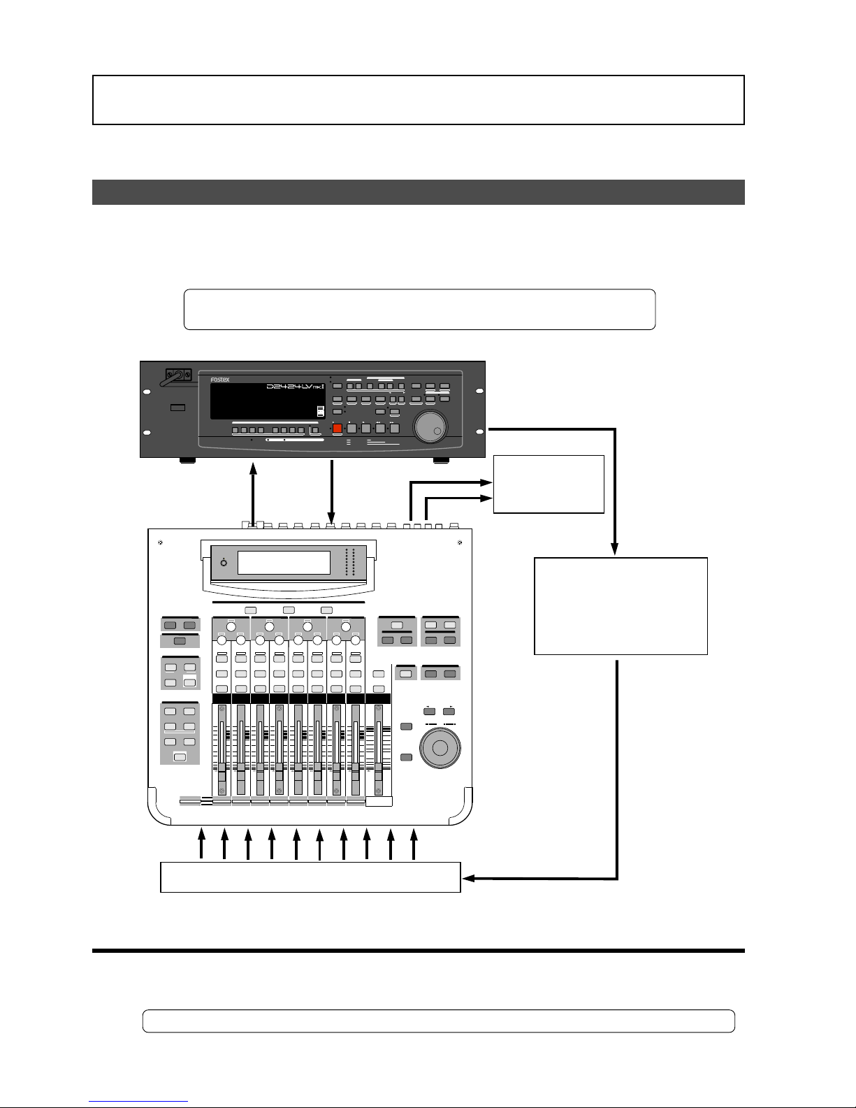
Model D2424LVmkII Reference Manual (MIDI Sync Function)
80
MIDI Sync Function
The following are examples concerning general types of systems using MIDI related functions
contained in the recorder.
MIDI clock sync system
By setting any desired meter at any desired point of the programmable tempo map contained in
the recorder, and by output of a MIDI clock and song position pointer according to the setting, a
hardware type MIDI sequencer can be synchronized as a MIDI clock slave. Consequently, in this
system, the recorder will be the master and the MIDI sequencer the slave.
* Restore the default settings on this recorder.
* Check for the correct program and proper sampling frequency.
• Connecting external equipment (Refer to connecting schematic)
(1) Connect the unit [MIDI OUT] to [MIDI IN] of the MIDI sequencer.
(2) Set the MIDI sequencer for “external sync mode (EXTERNAL SYNC) by MIDI clock.”
* Refer to the Owners Manual of the equipment in use for details.
MIDI OUT
MIDI IN
Q
FREQ
GAIN
Q
FREQ
GAIN
Q
FREQ
GAIN
+10
0
-10
-20
-30
-40
-
+10
0
-10
-20
-30
-40
-
+10
0
-10
-20
-30
-40
-
+10
0
-10
-20
-30
-40
-
+10
0
-10
-20
-30
-40
-
+10
0
-10
-20
-30
-40
-
+10
0
-10
-20
-30
-40
-
16
PAN
Q
PAN
ON ON ON ON ON ON ON
SOLO SOLO SOLO SOLO SOLO SOLO SOLO
EQ EDIT
EQ EDIT EQ EDIT
EQ EDIT EQ EDIT
EQ EDIT EQ EDIT
EQ EDIT
SOLO
ON ON
SOLO
STORERECALL
EQ ON
STORERECALL
STORERECALL
SOLO
+1/
/-1
DATA
EXIT
ENTER
MASTER
15
1413
1211
10
9
1-8 ANALOG IN
9-16 ADAT IN
17-20 EFF RTN
AUX1 AUX2
AUX3 AUX4
EFF1 EFF2
ADD.AUX
+10
0
-10
-20
-30
-40
-
ADAT IN
0
-10
-20
-30
-60
-
-40
PANPANPANPANPANPAN
-40
-36
-24
-18
-12
-9
-6
-3
OL
ST BUSS/SOLO
LR
METER
CHANNEL
FADER MODE
KEY MODE
METER
CHANNEL/
CH VIEW
PHASE GROUP
ROUTING/ PAIR/
MMC SEND
CURRENT SCENE STATUS
SETUP
SYSTEM MIDI
EQ/LO
EQ/LO-MID
EQ/HI-MID
EQ/HI-MID
FREQ
GAIN
EFF EDIT
EFF 2EFF 1
EQ LIBRARY
EFF LIBRARY
SELECTED EQ
SCENE MEMORY
REC BUSS
8
7
6
5
4
20
1 2 3
19
18
17
ANALOG IN
EFF RTN
PAGE SELECT
MIDI OUT
MIDI IN
MIDI clock & song position pointer
Master Recorder
MIDI sound sources
MIDI Sequencer
POWER
HOLD
RECORD
STOP
PLAY
REW
F FWD
ALL INPUT
ALL READY
LOCATE REC END
VARI PITCH
PUNCH
LOCATE
REHEARSAL
TAKE
RECALL
STORE
EXIT/NO
EXECUTE/YES
PGM SEL
NEXT
PREV
UNDO/REDO
PREVIEW
EDIT SETUP
AUTO RTN
OUTIN
AUTO PLAY
START
OUTIN
END
17-24
ACCESS
9-16
1/9/17
2/10/18
3/11/19
4/12/20 5/13/21 6/14/22 7/15/23
8/16/24
FOOT SW
LOCATE ABS 0
CLIPBOARD PLAY
AUTO
TRACK SHIFT
SHIFT
DISP SEL
CHARACTER
TIME BASE SEL
P.EDIT
EJECT
ENVELOPE
CHASE
TC READY TC GEN M.UNDO
TRACK SHIFT
PREV TC
NEXT TC
RECORD TRACK
CLIPBOARD
AUTO PUNCH
AUTO RTN
LOCATE MEMORY
24bit
96kHz
OPTICAL
24TRACK DIGITAL RECORDER
Page 81
Model D2424LVmkII Reference Manual (MIDI Sync Function)
81
• Setup of the D2424LVmkII
(1) Because the MIDI clock and song position pointer will be output from the recorder, set the SETUP mode
“Setting MIDI sync output signal” to “CLK.”
* Initial setting: MTC
* Permissible setting: CLK (MIDI clock and song position pointer:”CLK”)
MTC (MIDI time code: “MTC”)
Off (No output of MIDI sync signal)
* This item can be setup for each program.
* The setting can be saved/loaded as song data.
* This setting will be held even though power is switched OFF.
Refer to page “
114
”, SETUP mode “Setting MIDI sync output signal” for correct operating procedures.
(2) The meter in the desired bar can be set by “Time signature setting” of the SETUP mode.
* Initial setting: 001 bar, 4/4 signature.
* Permissible bar setting: 001~999
* Permissible meter setting: 1/4, 2/4, 3/4, 4/4, 5/4, 1/8, 3/8, 5/8, 6/8, 7/8, 8/8,
— — (Elimination of signature)
* Permissible setting of maximum number of points: 64 points
* This item can be set for each program.
* The setting can be saved/loaded as song data.
* This setting will be held even though power is switched OFF.
Refer to page “
110
”, SETUP mode “Time Signature Setting” for operating procedure.
(3) Tempo in the desired bar can be set by “Tempo setting” of the SETUP mode.
Tempo map is made in steps 2 and 3.
* Initial setting: 001 bar, 1st meter, Tempo120.
* Permissible bar setting: Follows the previous “Setup of the time signature.”
* Permissible signature setting: Follows the previous “Setup of the time signature.”
* Permissible setting of tempo: Quarter note=30~250 .... (Tempo elimination)
* Permissible setting of maximum number of points: 64 points
* This item can be set for each program.
* The setting can be saved/loaded as song data.
* This setting will be held even though power is switched OFF.
Refer to page “
112
”, SETUP mode “Setting a tempo” for operating procedure.
(4) Set the SETUP mode “Metronome setting” to ON if click sound is to be output according to the setup
tempo map.
* Initial setting: Off
* Permissible setup item: Off, On
* This item can be set for each program.
* The setting can be saved/loaded as song data.
* This setting will be held even though power is switched OFF.
Refer to page “
113
”, SETUP mode “Setting the Metronome function” for operating procedure.
(5) Press the [DISP SEL] key while holding down the [SHIFT] key, and then change the time base display to
BAR/BEAT/CLK.
• Confirming the MIDI clock sync
During recording and at playback following the recording, the time base (BAR/BEAT/CLK) is
displayed in accordance to the setup tempo map, and the MIDI clock and song position pointer
is also output.
Confirm that the travel position (BAR/BEAT/CLK) of the recorder and the travel position of the
synchronized MIDI sequencer are matched.
Page 82
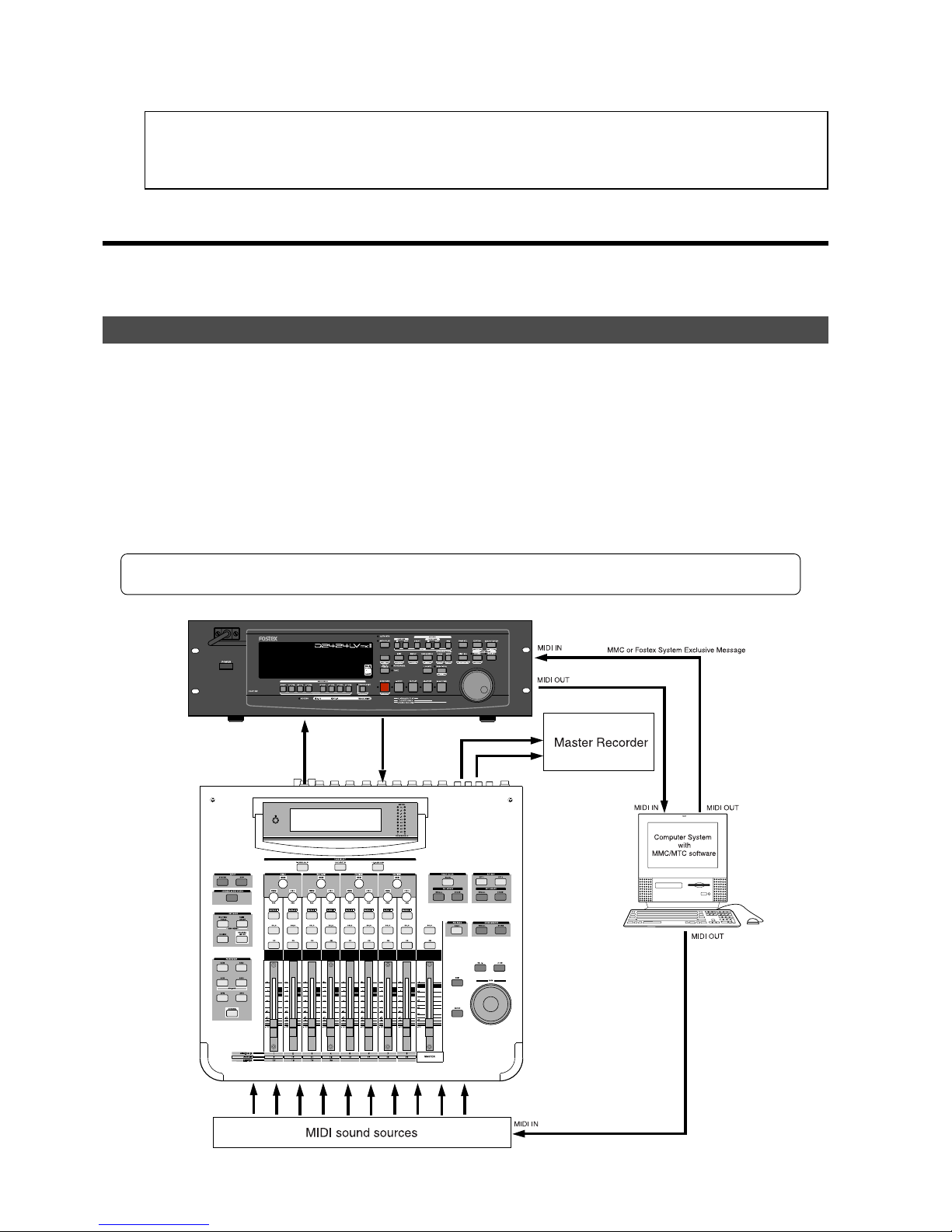
Model D2424LVmkII Reference Manual (MIDI Sync Function)
82
* If correct sync cannot be obtained, re-check the connections/cables and setting of both equipment.
<Note>:
In the recorder, the “
ABS 0
” position is set at “
-002BAR/1BEAT /00CLK
.”
This setting is made in consideration of the time required (it will not sync immediately) for the MIDI sequencer,
etc. to enter into sync. As a result, if the recorder is played back from ABS 0 (LOCATE ABS 0), sync will be
completed by the time it reaches the first bar, and will thus synchronize from head of the tune.
• Execution of recording
Various ways of recording can be conducted while synchronizing the recorder and the MIDI
sequencer with the MIDI clock.
MTC sync/MIDI machine control system
The following will explain synchronization by the MTC (MIDI time code) output and the computer
controlling system using MMC (MIDI machine control). In this system, the recorder will be the
master and the computer (with sequence software) will be the slave. The recorder will attach
any desired offset (time difference) against ABS time (absolute time) and output it as MTC in any
desired frame rate. It can also carry out the proper operation upon receiving an MMC and
Fostex System Exclusive Message from outside. In this case, because the recorder can setup a
DEVICE ID number by the SETUP mode “MIDI Device ID Setting” menu, a multiple number of the
unit’s can be separately controlled by changing the DEVICE ID numbers in the transmitted message
from the computer. In regards to the corresponding content for MMC, refer to the “MMC list” on
page “129” and on the Fostex System Exclusive Message, the “Fostex Exclusive List” on page “130.”
* Set the recorder in the initial state.
* Confirm the program and sampling frequency.
24TRACK DIGITAL RECORDER
Page 83
Model D2424LVmkII Reference Manual (MIDI Sync Function)
83
• Connecting to external equipment
Connect the recorder MIDI IN/OUT to the computer (with MIDI interface) MIDI IN/OUT (MMC/
MTC complied sequence software is activated in the computer).
• Setup of external equipment
Setup the following in the sequence software.
* Set to MTC external sync mode (EXTERNAL SYNC).
* Set for output of MMC.
* Set to the desired MTC read out frame rate.
* Set start time of the tune (which MTC time is to be the first bar). Refer to precaution in regards to MTC
offset, farther on.
For details, refer to Owners Manual of the external equipment.
• Setup of the D2424LVmkII
(1) Because MTC will be output from the recorder, set to “MTC” the SETUP mode “Setting MIDI sync output signal.”
Refer to page “
114
”, SETUP mode “Setting MIDI sync output signal” for operating procedure.
(2) Set a random offset time by the SETUP mode “Setting an MTC offset value.”
* Initial setting: 00H (Hour) 59M (Minute) 57S (Second) 00F (Frame) 00SF (Sub Frame)
* Permissible setup time: 00H 00M 00S 00F 00SF ~ 23H 59M 59S 29F 99SF
* This item can be set for each program.
* The setting can be saved/loaded as song data.
* This setting will be held even though power is switched OFF.
Refer to page “
115
”, SETUP mode “Setting an MTC offset value” for operating procedure.
(3) In the SETUP mode “Setting Offset mode,” whether the MTC offset time setup in Step 2 should be output (ABS)
at the ABS 00M 00S 00F 00SF position or at the 001BAR 1BEAT 00CLK (bar, signature) must be selected.
* Initial setting: ABS
* Permissible setup item: ABS, Bar Beat
* This item can be setup for each program.
* The setting can be saved/loaded as song data.
* This setting will be held even though power is switched OFF.
Refer to page “
115
”, SETUP mode “Setting Offset mode” for operating procedure.
(4) Setup to the same frame rate as that setup by the sequence software by “Setting an MTC frame rate” of the
SETUP mode.
* Initial setting: 25 frames
* Permissible setup of frame rate: 24, 25, 29.97nd, 29.97df, 30nd, 30df
* This item can be setup for each program.
* The setting can be saved/loaded as song data.
* This setting will be held even though power is switched OFF.
Refer to page “
114
”, SETUP mode “Setting an MTC frame rate” for operating procedure and details.
(5) Set to the same figure as the sequence software MMC device number (and Fostex System Exclusive Message
device number) by the SETUP mode “Setting the MIDI device number.”
When the sequence software transmits by “7F,” it means “ALL DEVICE” and therefore, it need not be setup.
Page 84
Model D2424LVmkII Reference Manual (MIDI Sync Function)
84
* Initial setting: 00
* Permissible setup ID: 00 ~ 99
* This item will be the setting common to all programs.
* This setting cannot be saved/loaded as song data.
* This setting will be held even though power is switched OFF.
Refer to page “
120
”, SETUP mode “Setting the MIDI device number” for operating procedure and details.
(6) Press the [DISP SEL] key while holding down the [SHIFT] key to show time base in the MTC display.
<Notes on MTC related setups>
By “
MTC offset time setting
” and “
MTC offset mode setting
,” at what position (ABS 0 or 001BAR/1BEAT/
00CLK) should the setup MTC (MTC offset time) is to be output is set. When setting the start time of
the tune in the sequence software by these setups, be careful of the following points.
• Offset mode: For ABS
If playback is started from ABS 0, since MTC will be output starting from the MTC offset time that has
been set, the start time of the tune set by the sequence software must be set about 3 seconds later
from the MTC offset time that was setup. This will provide time because the sequence software
cannot sync immediately after MTC is output. For example, if the initial setting of “
00H 59M 57S 00F
00SF
” is used, set the start time of the tune to “
01H 00M 00S 00F
.”
If playback is thus started from ABS 0 (LOCATE ABS 0), sync will be obtained by the time it reaches
the first bar and therefore it can be made to sync from the head of the tune.
• Offset mode: For BAR BEAT
As mentioned before, because the “
ABS 0
” position is set at the “
002BAR / 1BEAT / 00CLK
” position, the
setup MTC offset time can be set to the head of the tune without taking into account the time until
reaching sync, as mentioned above. The length of the time two bars beforehand will change in
accordance to the first bar setting for “
signature”
and “
tempo
.” For example, it will be long if the
tempo is set slow. This mode can be effectively applied when using the MIDI clock and MTC in
parallel, and when using MTC for the sync signal while controlling the recorder with time base BAR/
BEAT/CLK.
• Confirming MTC sync/MMC
(1) During recording and at playback after recording, time base MTC is displa y ed according to the setting and MTC
is output at the same time.
Check that the recorder traveling position (MTC) and the traveling position of the sequence software in sync are
matched.
(2) Send MMC commands such as PLAY, STOP and LOCATE from the sequence software to see that the recorder
will be properly controlled.
When a correct MIDI command (MMC or FEX) is received, “MIDI” in the display will be lit for about 40msec.
There is no setting in the recorder to receive MMC or FEX but it will operate if a correct MIDI signal is input.
* If sync and control cannot be done correctly, re-check connections/cables and the setting of both equipment.
• Execution of recording
Carry out various recordings while synchronizing the recorder and a MIDI sequencer with the
MIDI clock.
Page 85
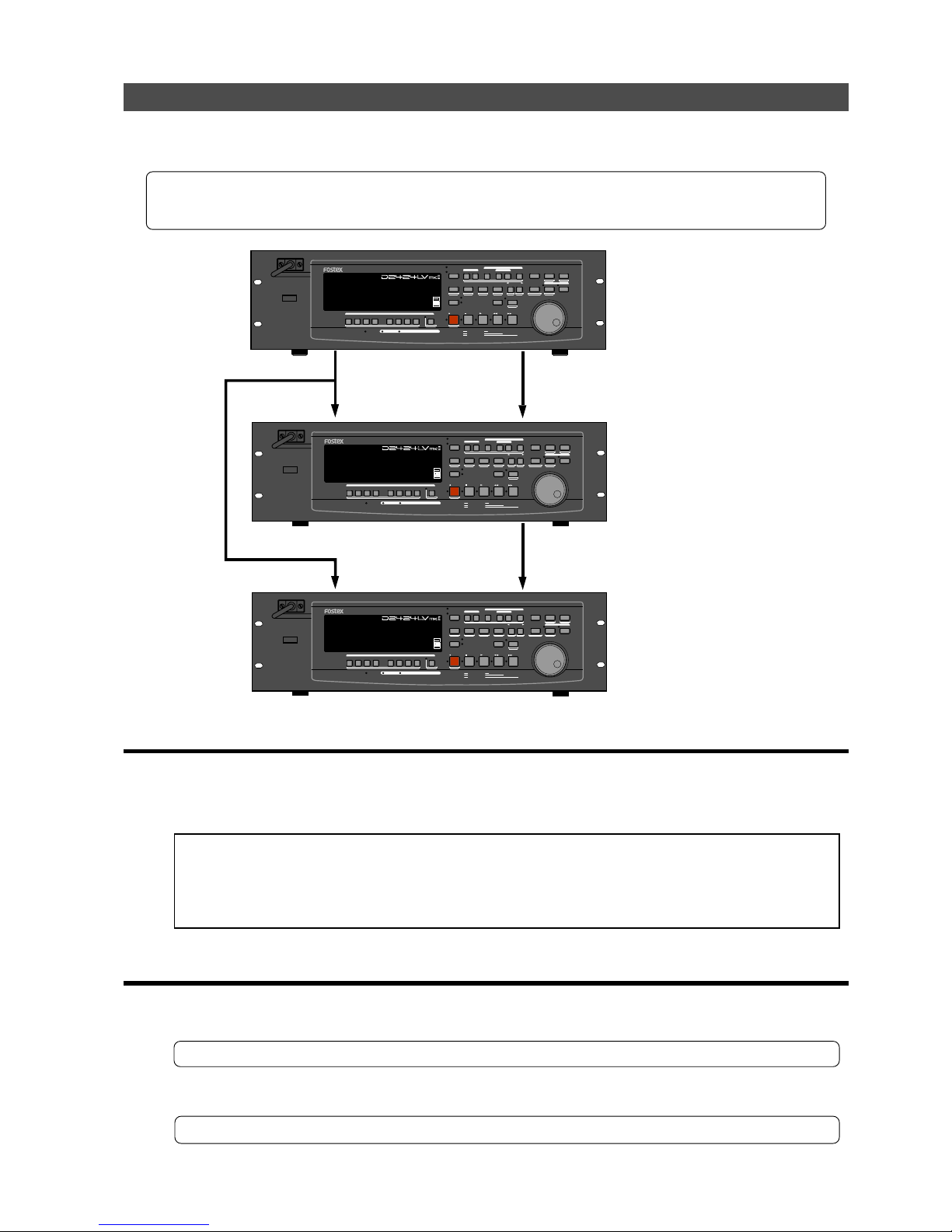
Model D2424LVmkII Reference Manual (MIDI Sync Function)
85
Multitrack system by the slave mode
An example of how to make a multitrack system by interconnecting three recorders in a slave
mode function, will be explained in the following.
* Initialize the recorder.
* Confirm the program.
* Set all three recorder’s to the same sampling frequency.
• Equipment interconnections
(1) From the recorder (#1) to the recorder (#2), connect WORD OUT to WORD IN and MIDI OUT to MIDI IN.
(2) From the recorder (#1) to the recorder (#3), connect WORD OUT to WORD IN.
(3) From the recorder (#2) to the recorder (#3), connect MIDI THRU (Note!!!) to MIDI IN.
<Notes>
* In order to slave drive the recorder with each other, the best setting is to supply word clock signals
together with MTC from the master.
* As shown in the above schematic, at input or the Word Clock from the master to the second slave, WORD
OUT from the master must always be branched to the second slave. Do not connect the first slave WORD
OUT to the second slave WORD IN .
• Setup of the recorder (#1): <Master>
(1) Because MTC, which is the reference for sync, is output fr om the recor der (#1), set the “Setting MIDI sync output
signal” of the SETUP mode to “MTC.”
Refer to page “
114
”, SETUP mode “Setting MIDI sync output signal” for operating procedure and details.
(2) A random frame rate to be used is set by the SETUP mode “Setting an MTC frame rate.”
Refer to page “
114
”, SETUP mode “Setting an MTC frame rate” for operating procedure and details.
Master <#1>
[Clock Sel?]=Int.
Slave <#2>
[Clock Sel?]=Word
Slave <#3>
[Clock Sel?]=Word
MIDI IN
MIDI OUT
MIDI IN
MIDI THRU
WORD IN
WORD OUT
WORD IN
POWER
HOLD
RECORD
STOP
PLAY
REW
F FWD
ALL INPUT
ALL READY
LOCATE REC END
VARI PITCH
PUNCH
LOCATE
REHEARSAL
TAKE
RECALL
STORE
EXIT/NO
EXECUTE/YES
PGM SEL
NEXT
PREV
UNDO/REDO
PREVIEW
EDIT SETUP
AUTO RTN
OUTIN
AUTO PLAY
START
OUTIN
END
17-24
ACCESS
9-16
1/9/17
2/10/18
3/11/19
4/12/20 5/13/21 6/14/22 7/15/23
8/16/24
FOOT SW
LOCATE ABS 0
CLIPBOARD PLAY
AUTO
TRACK SHIFT
SHIFT
DISP SEL
CHARACTER
TIME BASE SEL
P.EDIT
EJECT
ENVELOPE
CHASE
TC READY TC GEN M.UNDO
TRACK SHIFT
PREV TC
NEXT TC
RECORD TRACK
CLIPBOARD
AUTO PUNCH
AUTO RTN
LOCATE MEMORY
24bit
96kHz
OPTICAL
POWER
HOLD
RECORD
STOP
PLAY
REW
F FWD
ALL INPUT
ALL READY
LOCATE REC END
VARI PITCH
PUNCH
LOCATE
REHEARSAL
TAKE
RECALL
STORE
EXIT/NO
EXECUTE/YES
PGM SEL
NEXT
PREV
UNDO/REDO
PREVIEW
EDIT SETUP
AUTO RTN
OUTIN
AUTO PLAY
START
OUTIN
END
17-24
ACCESS
9-16
1/9/17
2/10/18
3/11/19
4/12/20 5/13/21 6/14/22 7/15/23
8/16/24
FOOT SW
LOCATE ABS 0
CLIPBOARD PLAY
AUTO
TRACK SHIFT
SHIFT
DISP SEL
CHARACTER
TIME BASE SEL
P.EDIT
EJECT
ENVELOPE
CHASE
TC READY TC GEN M.UNDO
TRACK SHIFT
PREV TC
NEXT TC
RECORD TRACK
CLIPBOARD
AUTO PUNCH
AUTO RTN
LOCATE MEMORY
24bit
96kHz
OPTICAL
24TRACK DIGITAL RECORDER
24TRACK DIGITAL RECORDER
POWER
HOLD
RECORD
STOP
PLAY
REW
F FWD
ALL INPUT
ALL READY
LOCATE REC END
VARI PITCH
PUNCH
LOCATE
REHEARSAL
TAKE
RECALL
STORE
EXIT/NO
EXECUTE/YES
PGM SEL
NEXT
PREV
UNDO/REDO
PREVIEW
EDIT SETUP
AUTO RTN
OUTIN
AUTO PLAY
START
OUTIN
END
17-24
ACCESS
9-16
1/9/17
2/10/18
3/11/19
4/12/20 5/13/21 6/14/22 7/15/23
8/16/24
FOOT SW
LOCATE ABS 0
CLIPBOARD PLAY
AUTO
TRACK SHIFT
SHIFT
DISP SEL
CHARACTER
TIME BASE SEL
P.EDIT
EJECT
ENVELOPE
CHASE
TC READY TC GEN M.UNDO
TRACK SHIFT
PREV TC
NEXT TC
RECORD TRACK
CLIPBOARD
AUTO PUNCH
AUTO RTN
LOCATE MEMORY
24bit
96kHz
OPTICAL
24TRACK DIGITAL RECORDER
Page 86
Model D2424LVmkII Reference Manual (MIDI Sync Function)
86
(3) With the SETUP mode “Setting Offset mode,” whether the MTC offset time will be output (ABS) at the ABS 00H
00M 00S 00F 00SF point or at the 001BAR 1BEAT 00CLK (bar/signature) point of the tempo map, is selected.
Refer to page “
115
”, SETUP mode “Setting Offset mode” for operating procedure and details.
(4) A random offset time is set by the SETUP mode “Setting an MTC offset value.”
Refer to page “
115
”, SETUP mode “Setting an MTC offset value” for operating procedure and details.
(5) “00” is set with the SETUP mode “Setting the MIDI device number.”
Refer to page “
120
”, SETUP mode “Setting the MIDI device number” for operating procedure and details.
(6) Set to “Int.” the clock setting by the SETUP mode “Setting the operating clock.”
Refer to page “
120
”, SETUP mode “Setting the operating clock” for operating procedure and details.
(7) Press the [DISP SEL] key while holding down the [SHIFT] key to change the time base display to MTC.
• Setup of the recorder (#2) <Slave 1> and (#3) <Slave 2>
(1) Set the SETUP mode “Setting an MTC frame rate” to the same frame rate as in the recorder (#1).
Refer to page “
114
”, SETUP mode “Setting an MTC frame rate” for operating procedure and details.
(2) Set the SETUP mode “Setting Offset mode” to the same mode as in the recorder (#1).
Refer to page “
115
”, SETUP mode “Setting Offset mode” for operating procedure and details.
(3) Set the SETUP mode “Setting an MTC offset value” to the same offset time as in the recorder (#1).
Refer to page “
115
”, SETUP mode “Setting an MTC offset value” for operating procedure and details.
(4) Set the SETUP mode “Setting the MIDI device number,” to “01” in the recorder (#2), and to “02” in the recorder
(#3).
Refer to page “
120
”, SETUP mode “Setting the MIDI device number” for operating procedure and details.
(5) Press the [EXECUTE/YES] key While holding down the [SHIFT] key, set slave mode to “On.”
“CHASE” indicator will be flashing in the display.
* Slave type initial setting: Vari
* Permissible setup item: Vari, Free, Once
* This item can be set for each program.
* The setting can be saved/loaded as song data.
* This setting will be held even though power is switched OFF.
Refer to page “
116
”, SETUP mode “Setting the slave type”, for operating procedure and details.
(6) Using the SETUP mode “Setting the slave type,” set slave type to “Free.”
(8) Press the [DISP SEL] key while holding down the [SHIFT] key, to change the time base display to MTC.
(7) Set to “Word” the clock setting by the SETUP mode “Setting the operating clock.”
Refer to page “
120
”, SETUP mode “Setting the operating clock” for operating procedure and details.
Page 87
Model D2424LVmkII Reference Manual (MIDI Sync Function)
87
<Notes>
After this setup, check the following in the recorder (#2) and (#3).
• Blinking of “
CHASE
” in the display: This will change to constant lit upon completing chase
lock in lateroperation.
• “
EXT
” and “
WORD
” are lit in the display: This means it is externally synchronized against
the input word clock signal.
• Check chase lock
(1) When the master recorder (#1) is played back, MTC IN LED of the slave recor der (#2) and (#3) will be lit, “CHASE”
in the display will immediately change from blinking to lit and chase lock will be completed.
Check that the MTC time on display are same in both master and slave units.
(2) When the master starts recording, the slave will also start recording upon completing chase lock.
(3) When the master is stopped, the slave will also stop as MTC from the master will be interrupted.
“CHASE” in the display will change from lit to blinking.
(4) During FF/REW, the master only will be in the FF/REW mode and the slaves will remain stopped but when
playback/recording is started, the slaves will immediately chase lock.
<Note>:
The unit re-chase window is fixed at “
10 frame
.” In other words, when MTC of the master and slave
drifts apart more than 10 frames, it will assume that chase lock is disengaged and the slave will match the
position again with the master (re-chase operation). During the re-chase operation, sound output will be
muted. If the drift is within 10 frames, the slave will recognize this and continue to travel.
Because the master supplies digital signal to slave in this system, re-chase is rarely carried out following
chase lock.
* Should the unit fail to correctly chase lock and control, re-check the connection /cables and all
settings.
• Execution of recording
A variety of recording work can be carried out with all three recorder’s in the chase lock mode.
Page 88
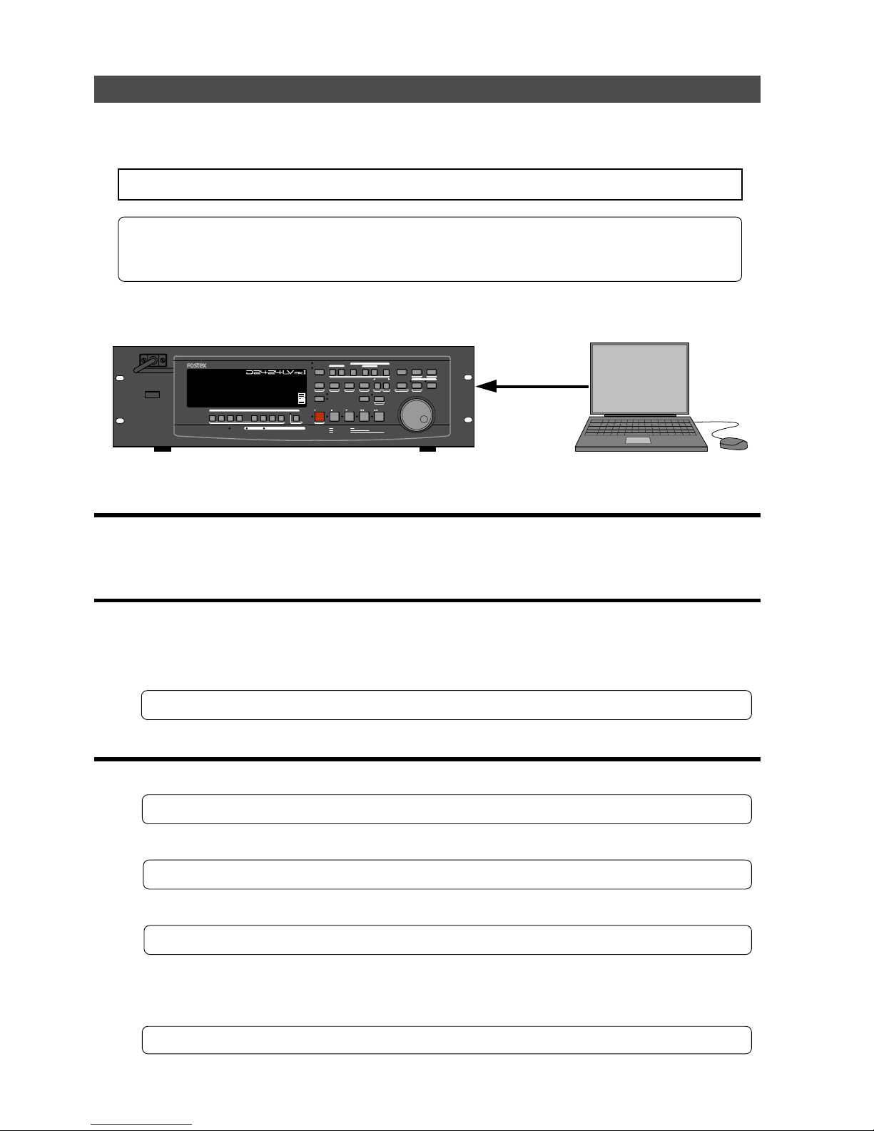
Model D2424LVmkII Reference Manual (MIDI Sync Function)
88
(5) Set slave type to “Vari” by the SETUP mode “Setting the slave type.”
Refer to page “
116
”, SETUP mode “Setting the slave type” for operating procedure and details.
<Slave>
<Master>
Computer with MMC/MTC
software
External MIDI equipment sync system by the slave mode
Up to this point, synchronization with external MIDI equipment has been explained with the
recorder as the master and MIDI equipment as the slave but depending on the slave mode setting,
the MIDI equipment can be set as the master and the recorder as the slave.
<Note>:
External MIDI equipment which can be used as the master is limited to those which can output MTC.
* Initialize the recorder.
* Confirm the program and sampling frequency.
* In the following, the explanation will be on the assumption that a computer (with sequence software) is
used.
• Connection to external equipment
Connect MIDI OUT of the computer (with MIDI interface) with MIDI IN of the recorder.
The computer sequence software complying to MMC/MTC must be activated.
• Setup of external equipment
Sequence software is setup as follows.
* Set for output of MTC.
* Set frame rate of the MTC to be output.
* Confirm start time of the tune.
Refer to Owners Manual of the respective equipment for details.
• Setup of the D2424LVmkII
(1) Set to same frame rate as the sequence software by the SETUP mode “Setting an MTC frame rate.”
Refer to page “
114
”, SETUP mode “Setting an MTC frame rate” for operating procedure and details.
(2) Set to the desired mode by the SETUP mode “Setting offset mode.”
Refer to page “
115
”, SETUP mode “Setting offset mode” for operating procedure and details.
(3) A random offset time can be set by the SETUP mode “Setting an MTC offset value.”
Refer to page “
115
”, SETUP mode “Setting an MTC offset value” for operating procedure and details.
(4) Press the [EXECUTE/YES] key holding down the [SHIFT] key, set the slave mode to “On.”
MIDI IN
MIDI OUT
POWER
HOLD
RECORD
STOP
PLAY
REW
F FWD
ALL INPUT
ALL READY
LOCATE REC END
VARI PITCH
PUNCH
LOCATE
REHEARSAL
TAKE
RECALL
STORE
EXIT/NO
EXECUTE/YES
PGM SEL
NEXT
PREV
UNDO/REDO
PREVIEW
EDIT SETUP
AUTO RTN
OUTIN
AUTO PLAY
START
OUTIN
END
17-24
ACCESS
9-16
1/9/17
2/10/18
3/11/19
4/12/20 5/13/21 6/14/22 7/15/23
8/16/24
FOOT SW
LOCATE ABS 0
CLIPBOARD PLAY
AUTO
TRACK SHIFT
SHIFT
DISP SEL
CHARACTER
TIME BASE SEL
P.EDIT
EJECT
ENVELOPE
CHASE
TC READY TC GEN M.UNDO
TRACK SHIFT
PREV TC
NEXT TC
RECORD TRACK
CLIPBOARD
AUTO PUNCH
AUTO RTN
LOCATE MEMORY
24bit
96kHz
OPTICAL
24TRACK DIGITAL RECORDER
Page 89

Model D2424LVmkII Reference Manual (MIDI Sync Function)
89
(6) Press the [DISP SEL] key while holding down the [SHIFT] key, to change the time base display to MTC.
<Precautions at MTC related setups>
The position (ABS 0 or 001BAR/1BEAT/00CLK) when the setup MTC (MTC offset time) should be
output was setup by the “
MTC offset time setting
” and “
MTC offset mode setting
.” In accordance to start
time of the tune set by the sequence software, setup as explained below.
Offset mode: For ABS
Set the MTC offset time about three seconds prior to the start time of the tune set by the sequence
software. Because the recorder cannot immediately chase lock after input of MTC, in order to sync
the unit from head of the tune, set the preroll using the sequence software, and playback from before
the actual head of the tune to allow the recorder to enter into sync by the time it arrives at the head
of the tune.
Offset mode: For BAR/BEAT
The MTC offset time can be set to the same time as the start time of the tune set by the sequence
software. Because the “
ABS 0
” position is set at the “
002BAR/1BEAT/00CLK
” position in the unit, as
mentioned before, the preceding time required for sync is already set. The preceding time of two bar
lengths could change in length depending on the first bar’s “signature setting” and “tempo setting”
mentioned before. For example, it will be longer if the tempo is slowed down.
• Confirming chase lock
(1) When the sequence software is played, MTC IN LED of the recorder will light, “CHASE” in the displa y will change
from blinking to lit and the chase lock will be completed.
Check that the MTC output by the sequence software and MTC time displayed in the recorder are the same.
(2) When the sequence software stops, MTC will be interrupted and the recorder will also stop.
“CHASE” in the display will change from lit to blinking.
(3) During FF/REW of the sequence software, the recorder will remain stopped but upon starting to record, the
recorder will immediately chase lock.
<Note>:
Chase lock of the recorder by MTC only is permissible when speed difference of the MTC
from the master is within +/- 5.6%. Against the MTC within this range, variable pitch will be constantly
applied internally for chasing. Chase lock, however, will not function against MTC at a speed difference
outside this range. Also, when the master speed difference is large, it is advised to let the recorder
learn the master speed by entering PLAY prior to recording. By doing so, it will be lock faster from the
second and later sessions.
* Should it not be possible to chase lock, re-check connections / cables and all settings.
• Execution of recording
Carry out various recordings while the recorder is chase locked to the sequence software.
<One Point Advice>
Sync signal “Free” of the “Slave mode setting” menu:
When the recorder is made to chase lock by MTC only, variable pitch will be constantly applied by
external MTC. If a digital signal is output to an external digital equipment from the recorder, it will
not be able to follow the speed difference (MTC speed difference of the master) of the recorder and
the external digital equipment, in some cases, may not be able to input a continuous digital signal.
As a counter measure, the sync signal should be set to “Free” by the “Slave mode setting” menu. Using
this setting, the recorder will enter self operation by the internal clock, after completion of chase
lock, and it will be possible to supply a stable digital signal to the external equipment.
Under this setting, when MTC drift between the master recorder and slave recorder exceeds 10 frames,
the recorder will assume that chase lock has been disengaged and the slave recorder will carry out
position matching again with the master unit (re-chase operation). During the re-chase operation,
sound output will be muted and the digital signal will also be interrupted. If it is within 10 frames,
the slave recorder will continue to run while admitting this drift.
Page 90
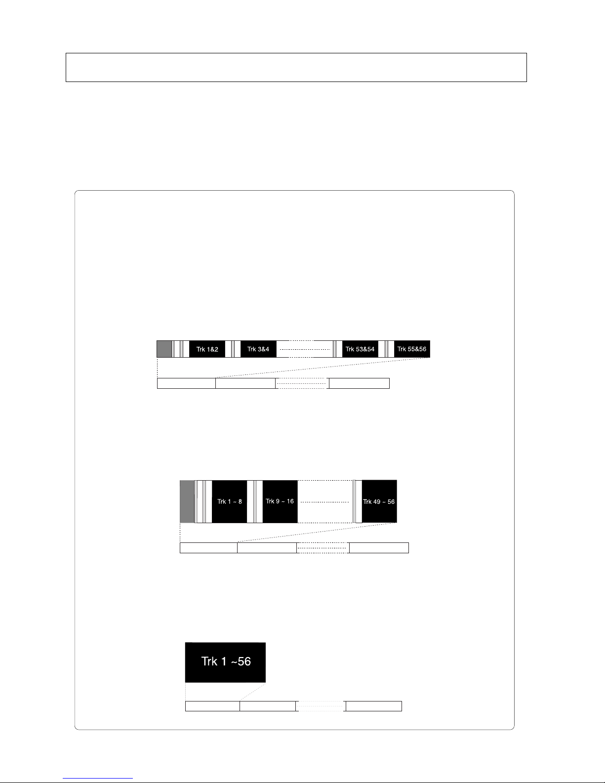
Model D2424LVmkII Reference Manual (Saving and Loading Song Data)
90
Saving and Loading Song Data
The unit allows you to save song data of a selected program (audio data + setup data) to an external audio
recorder (DAT, adat, etc.) or a CompactFlash
TM
card (in the FDMS-3 Ver.3.0 format). The saved song data can
be loaded to the unit. By temporarily saving data of a finished or unfinished song to an external medium you
can load it to the unit later for editing, additional recording, etc. You can also save a song to a DOS formatted
CompactFlash
TM
card as a WAV file, which also can be edited using a computer.
Furthermore, by installing the optional E-IDE hard disk instead of the pre-installed CF drive, you can save
song data to the hard disk in the FDMS-3 Ver.3.0 or WAV format. (To install the optional E-IDE hard disk, the
optional Model 9044 (bay + caddy) must be mounted.)
**********About saved and loaded data**********
The data format and time required to SAVE/LOAD song data will vary between saving and loading with a
DAT using S/P DIF digital signals, saving and loading with an adat device using adat digital signals, or
saving and loading with a CompactFlash
TM
card (or a optional E-IDE hard disk drive).
S/PDIF digital signal (You can save and load each Program individually.):
Following about five seconds of pilot signal (shown in the diagram below), song data in the current drive
is output to a connected DAT. Two tracks of audio data (shown in black in the diagram) are output.
To save data from Real tracks 1-24, two-track data will be output twelve times, which takes twelve as much
time as the song duration (ABS 0 to REC END). To save all data including Additional tracks 1-56, two-track
data will be output twenty eight times, which takes twenty eight times the song duration. Saved data is also
loaded two tracks at a time.
adat digital signal (You can save and load each Program individually.):
After about five seconds of pilot signal (shown in gray in the diagram below), song data in the current
drive is output to a connected adat. Eight-track audio data (shown in black in the diagram) is output.
To save the data from Real tracks 1-24, data will be output three times, which takes the same amount of
time as the song duration (ABS 0 to REC END).
To save all data including Additional tracks 1-56, eight-track data will be output seven times, which takes
seven times the song duration. Saved data is also located eight tracks at a time.
CompactFlashTM card or optional E-IDE hard disk drive:
(You can save and load each Program individually or all program.)
All Real track data and Additional track data is output simultaneously to a CompactFlashTM card (or optional
E-IDE hard disk drive) as shown in black in the diagram. Therefore, saving and loading a Program takes
much less time relative to a DAT or adat. No pilot signal or beep is recorded. You can also save/load WAV
files in DOS formatted disk.
Program 99 (P99)
Program 2 (P02)Program 1 (P01)
Program 99 (P99)
Program 2 (P02)Program 1 (P01)
Program 99 (P99)
Program 2 (P02)Program 1 (P01)
Page 91

Model D2424LVmkII Reference Manual (Saving and Loading Song Data)
91
<The following items can be saved and loaded as song data>
Memory data: CLIPBOARD IN/OUT, AUTO RTN START/END, AUTO PUNCH IN/OUT point data
Locate data (locate number 00~99): when saving and loading song data using a
CompactFlash
TM
card
Time Base: ABS, MTC, or BAR/BEAT/CLK
Setup mode: • Time signature setting (BAR BEAT), • Tempo setting, • Click On/Off setting
• Preroll Time setting, • Midi Sync Out setting, • MTC Frame Rate setting
• MTC Offset setting, • MTC Offset Mode setting, • Rec Protect On/Off setting
• Slave Mode on/off setting, • Slave Type setting, • Virtual TC Setting (when saving
and loading song data using a CompactFlash
TM
card)
<The following items cannot be saved or loaded as song data>
Auto Play mode and Auto Return mode On/Off
Vari-pitch mode On/Off, and pitch data
Setup mode: • Digital In setting, • Digital Out setting, • Bar/Beat Resolution On/Off setting
• Device ID setting, • Foot switch function setting, • Mark stop function setting
• Auto EE mode setting, • Chain play mode setting and chain list
• Reference level setting, • Bal/Unbal setting, • Contrast level setting
<Notes in using DAT and adat>
• Execution of save/load is permissible only in 44.1kHz/16 bit, 44.1kHz/24 bit, 48kHz/16 bit or
48kHz/24 bit asynchronous recording in S/P DIF format, or with digital devices that have the
adat format digital recording function.
• When a 24 bit data recorded in the recorder is saved to a 16 bit digital device, Audio 16 bit only
will be saved. Also, when a 20 bit data is saved, Audio 20 bit only will be saved.
• When loading DAT or adat data, if it is 16 bit, even if the current drive of the recorder has be
formatted in 24 bits, only the upper 16 bits will be loaded and the lower 8 bits will be "0."
Likewise, in a 20 bit machine, the upper 20 bits only will be loaded and the lower 4 bits will be
"0."
<Note when saving data using DAT or adat>
Song data can be saved as a real track, additional track or ALL data. Please note the following points
when saving song data using a DAT or adat device.
The save time of the data depends on the time of the song data (ABS 0-REC END) on the real track.
Therefore, if you attempt to save data that exists on an additional track that is longer than the data
on the real track, the data on the additional track will only be saved for the same amount of time as
the data on the real track.
Let’s say, you have 10 minutes recorded on the real track and you tentatively move it to the
additional track (track exchange function). Then you save a real track by leaving that moved
portion blank, which leaves you with only 3 minutes of recording on the track. This means only 3
minutes of the data on the additional track will be saved, and the remaining 7 minutes will not be
saved. If you want longer save time, you can edit the save time during save operations (Go to page
"
93
" <Step-6>).
This can be done by either setting the save time to a longer save time (however, the maximum time
that can be edited is 59 minutes 59 seconds), or move the data with the longest recording time on
the additional track to the real track and then save that data. Be careful not to erase the data that
you need on the additional track when conducting these procedures. For more details on track
exchange go to page "
77
."
Page 92
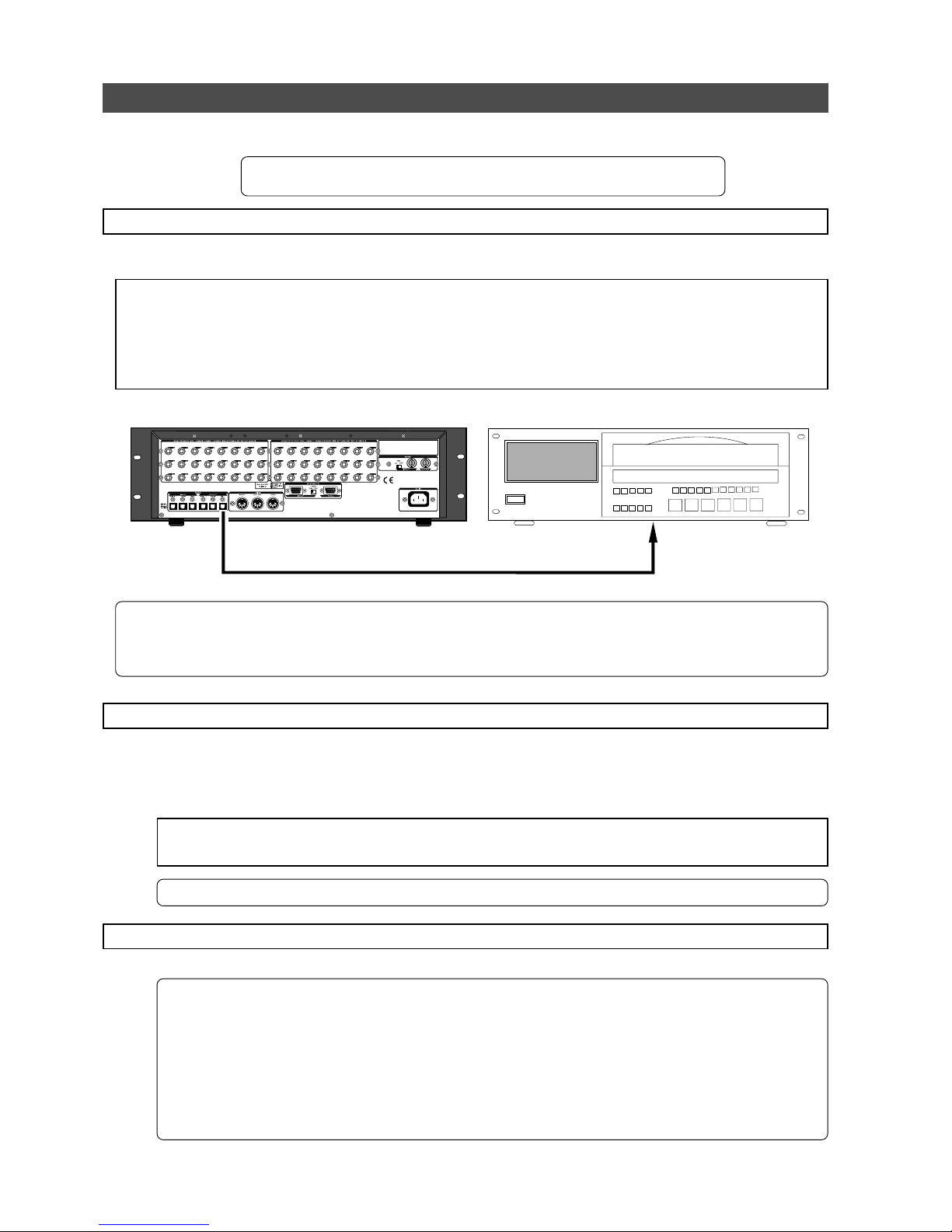
Model D2424LVmkII Reference Manual (Saving and Loading Song Data)
92
Saving the data using a adat or S/P DIF digital signal
S/P DIF digital signal (or adat digital signal) from the [DATA OUTPUT] connector of the recorder is saved.
* Restore the initial settings on the recorder.
* Set the same sampling rate on the external digital device and the recorder.
Connecting an external device
Connect [DATA OUTPUT] 1-8 connector of the recorder to the digital input connector on the external digital
device.
<Notes>
• The recorder has
[DATA OUTPUT]
connectors for an S/P DIF digital signal (OPTICAL) and for an adat digital signal.
These connectors have the same shape but carry different information.
Use the
[DATA OUTPUT] 1-8
connector to save data. Do not use the
[DATA OUTPUT] 9-16
and
17-24
connectors.
• Save/load by S/P DIF or adat digital signals cannot be executed from the current drive that is formatted in 96kHz/
24 bit or 88.2kHz/24 bit.
• If the external device has only COAXIAL type (RCA) digital I/O connectors, connect an optional COP-1/96k (optical/
coaxial converter) to use an S/P DIF digital signal.
• Connecting both output and input connectors on the recorder to the input and output connectors on the external
digital device respectively may generate a digital loop.
Setting up an external device
(1) Set the same sampling rate to that of the recorder.
(2) Select digital input on the external device so that the external device will accept a digital signal.
On some external devices, you may have to set up so that the external device will synchronize with the incoming
digital signal.
<Note>:
If the external device does not accept the digital signal or if you notice digital noise, check the
connection, cabling, and the settings of the recorder and the external device.
* Refer to the instruction manuals that came with any external digital device for details.
Executing the save operation
Use the “Save PGM?” menu in Setup mode.
• Output format available : adat, SPDIF, IDE2 (CompactFlash
TM
card or E-IDE hard disk drive)
• Programs available : When using an adat/SPDIF -> P01 - P99 (each program individually)
: When using a IDE2 -> P01 - P99 or All program
• Track available : When using an adat or DAT -> Tracks 1-8, 1-16, 1-24, 1-32, 1-40,
1-48, 1-56, 9-16, 9-24, 9-32, 9-40, 9-48, 9-56, 17-24, 17-32, 17-40,
17-48, 17-56, 25-32, 25-40, 25-48, 25-56, 33-40, 33-48, 33-56, 41-48, or
49-56
: When using a IDE2 -> All tracks (1-56) will be automatically
selected.
[DATA OUTPUT] 1-8
adat or DAT
adat In (or Digital In)
Page 93
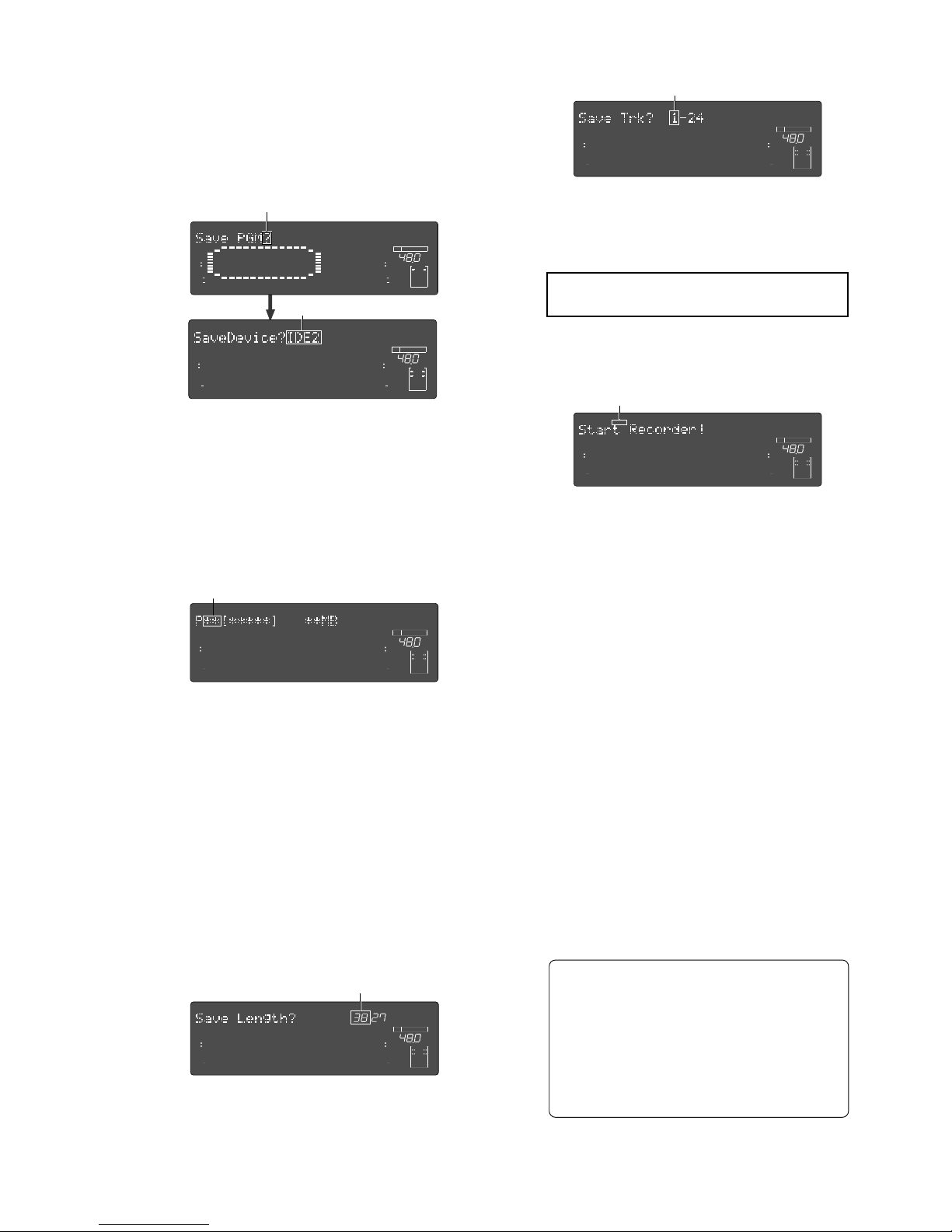
Model D2424LVmkII Reference Manual (Saving and Loading Song Data)
93
(1) Press the [SETUP] key.
The recorder enters Setup mode.
(2) Use the Jog dial to select “Save PGM?,” and then
press the [EXECUTE/YES] key.
The message “Save Device?” and an indication of
the digital signal to be saved (“SPDIF,” “adat, or
“IDE2” ) will flash on the display.
(3) Rotate the Jog dial to select a type of digital signal
("adat" or "SPDIF") format to be used for the save
operation.
Selecting “adat” will save data in the adat digital
signal format. Selecting “SPDIF” will save data in
the S/P DIF digital signal format.
(4) Press the [EXECUTE/YES] key.
Selection of the digital signal format for the save
operation will be confirmed, and the existing
Program numbers will flash on the display.
(5) Rotate the Jog dial to select a Program to save.
You can select any existing Program (up to 99) to
save.
(6) Press the [EXECUTE/YES] key.
The length of the time (ABS 0 - REC END) of the
program recording selected appears and the time
shown can be edited.
The time is usually saved according to the time
displayed, however, it is possible to shorten the time
to save at this stage when saving the time. In other
words, though the actual recording may be 9
minutes 00 seconds, as shown in the example below,
that time can be edited to 5 minutes when saved.
As mentioned in the <Note> on page 91, if the data
on the additional track is longer the time can be set
to a longer time and saved (however, the maximum
time that can be edited is 59 minutes 59 seconds).
(7) Press the [EXECUTE/YES] key again.
“Save Trk ? 1-24” (“1” is flashing) appears on the
display and you can select tracks to save.
(8) Select the desired track range using the Jog dial.
You can select 1, 9,17, 25, 33, 41, and 49 of the
points that are flashing (left). Use the Shuttle dial
to move the flashing cursor to the left, then turn
the Jog dial to select 8, 16, 24, 32, 40, 48 and 56.
<Note>:
Refer to the
<Note>
on page "91" prior
to saving data including the additional track.
(9) Press the [EXECUTE/YES] key.
“Start Recorder !” (Start recording on the recorder)
appears on the display, and “SURE?” flashes.
(10) Confirm that the external device is syncing with
the digital input signal, and start recording on the
external device (DAT or adat).
Setting a START-ID (DAT) or a locate point at the
recording start point will facilitate future loading
operations.
(11) Confirm that the recording on the external device
has started, and press the [EXECUTE/YES] key.
The save operation starts, and the time required
for the save operation appears on the display and
a few seconds later, it will start counting down.
This few seconds delay is due to the pilot signal
which is recorded to mark the beginning of the
Program to facilitate future load operation.
Therefore, the actual save operation starts when
counting down starts.
Two tracks are saved each time in the order of Track
1 and 2, 3 and 4, etc. to a DAT machine.
Eight tracks are saved each time in the order of
Track 1-8, 9-16, etc. to an adat machine.
(12) When data is successfully saved a “COMPLETED!”
message will appear on the display, and stop the
external DAT or adat.
(13) Press the [STOP] button or the [EXIT/NO] key to
quit the Setup mode.
The display will return to the previous time base
indication.
To cancel the operation or restore the indication
shown before you pressed the
[EXECUTE/YES]
key, press the
[STOP]
button or the
[EXIT/NO]
key.
Pressing one of these keys repeatedly takes you
to the previous layer, finally quitting the Setup
mode, and the display will return to the previous
time base indication. If you press the
[STOP]
button or the
[EXIT/NO]
key any time after you
execute the save operation but before it is
complete, the saved song data will be invalid.
42
OL
0
30
24
18
12
9
6
3
kHz
24
FS
BIT
SETUP
24
42
OL
0
30
24
18
12
9
6
3
232221201918
17
16151413121110
98765
4
3
2
1
CLOCK
INT
∞
42
OL
0
30
24
18
12
9
6
3
kHz
24
FS
BIT
SETUP
24
∞
42
OL
0
30
24
18
12
9
6
3
232221201918
17
16151413121110
98765
4
3
2
1
CLOCK
INT
∞
42
OL
0
30
24
18
12
9
6
3
kHz
24
FS
BIT
SETUP
24
∞
42
OL
0
30
24
18
12
9
6
3
232221201918
17
16151413121110
98765
4
3
2
1
CLOCK
INT
SM
∞
42
OL
0
30
24
18
12
9
6
3
kHz
24
FS
BIT
SETUP
24
∞
42
OL
0
30
24
18
12
9
6
3
232221201918
17
16151413121110
98765
4
3
2
1
CLOCK
INT
∞
42
OL
0
30
24
18
12
9
6
3
kHz
24
FS
BIT
SETUP
24
∞
42
OL
0
30
24
18
12
9
6
3
SURE?
232221201918
17
16151413121110
98765
4
3
2
1
CLOCK
INT
Flashing
Flashing
Flashing
Flashing
∞
42
OL
0
30
24
18
12
9
6
3
kHz
24
FS
BIT
SETUP
24
∞
42
OL
0
30
24
18
12
9
6
3
232221201918
17
16151413121110
98765
4
3
2
1
CLOCK
INT
Flashing
Flashing
Page 94
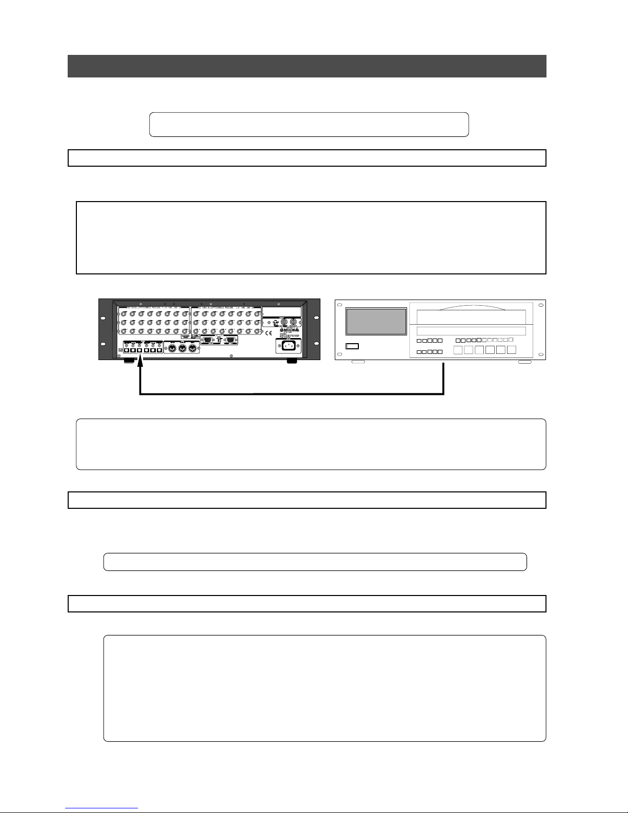
Model D2424LVmkII Reference Manual (Saving and Loading Song Data)
94
Loading the data using a adat or S/P DIF digital signal
Load the data by S/P DIF digital signals (or adat digital signals) from the [DATA INPUT] connector of the
recorder.
* Restore the initial settings on the recorder.
* Set the same sampling rate on the external digital device and the recorder.
Connecting the external device
Connect [DATA INPUT] connectors of the recorder to the digital output connectors on the external digital
device.
<Notes>
• The recorder has
[DATA INPUT]
connectors for an S/P DIF digital signal (OPTICAL) and for an adat digital signal.
These connectors have the same shape but carry different information.
Use the
[DATA INPUT] 1-8
connector. Do not use the
[DATA INPUT] 9-16
and
17-24
connectors.
• Do not remove the optical cable or perform any other operation that would disconnect the S/P DIF signal until
the session is complete. Otherwise, the recorder will generate noise, and affect the connected device.
• If the external device has only COAXIAL type (RCA) digital I/O connectors, connect an optional COP-1/96k (optical/
coaxial converter) to use an S/P DIF digital signal.
• Connecting both output and input connectors on the recorder to the input and output connectors on the external
digital device respectively may generate a digital loop.
Setting up an external device
(1) Setup the external device so that it can output a digital signal.
(2) Locate the beginning of the pilot signal recorded in the saved data.
* Refer to the instruction manual that came with your external digital device for details.
Executing the load operation
You will use the “Load PGM ?” menu in Setup mode.
[DATA INPUT] 1-8
adat or DAT
adat Out (or Digital Out)
• Output format available : adat, SPDIF, IDE2 (CompactFlash cardTM or E-IDE hard disk drive)
• Programs available : When using an adat/SPDIF -> P01 - P99 (each program individually)
: When using a IDE2 -> P01 - P99 or All program
• Track available : When using an adat or DAT -> Tracks 1-8, 1-16, 1-24, 1-32, 1-40,
1-48, 1-56, 9-16, 9-24, 9-32, 9-40, 9-48, 9-56, 17-24, 17-32, 17-40,
17-48, 17-56, 25-32, 25-40, 25-48, 25-56, 33-40, 33-48, 33-56, 41-48, or
49-56
: When using a IDE2 -> All tracks (1-56) will be automatically
selected.
Page 95
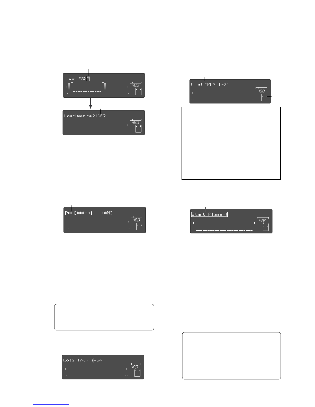
Model D2424LVmkII Reference Manual (Saving and Loading Song Data)
95
(1) Press the [SETUP] key.
The recorder will enter the Setup mode.
(2) Use the Jog dial to select “Load PGM ?,” and then
press the [EXECUTE/YES] key.
The message “Load Device?” and the type of digital
signal to be loaded (“SPDIF,” “adat,” or “IDE2”) will
flash on the display.
(3) Rotate the Jog dial to select the type of digital
signal format ("SPDIF" or "adat") to be used for
the load operation.
Selecting “adat” will load data in the adat digital
signal format. Selecting “SPDIF” will load data in
the S/P DIF digital signal format.
(4) Press the [EXECUTE/YES] key.
The digital signal selected is set and the program
number currently set on the load destination
current drive flashes. The size of the program
recording is also displayed.
(5) Rotate the Jog dial to select a Program into which
to load data.
You can select any existing Program (from up to
99).
If you select a Program that already contains data
and execute the load operation, the existing data
will be overwritten by the new data.
If you do not wish to overwrite any data in any
current Program, use the Jog dial to select
“New PGM” to execute the load operation.
You can do this only when the number of existing
Programs is 99 or less and the hard disk has enough
free space to accommodate the new data.
If a program that is already recorded with some
sort of data is selected and loaded, only the song
data loaded will be valid. All the data of the
programs recorded on that same track up to then
will be erased.
(6) Press the [EXECUTE/YES] key.
Now you can select tracks into which to load.
(7) Select the desired track range using the Jog dial.
You can select 1, 9, 17, 25, 33, 41 and 49 of the
points that are flashing (left). Use the Shuttle dial
to move the flashing cursor to the left, then turn
the Jog dial to select 8, 16, 24, 32, 40, 48 and 56.
(8) Press the [EXECUTE/YES] key. (“SURE?” flashes.)
"EXT" and "DIGITAL" will light up and "SURE?" will
flash in the display.
<Notes>
• If digital signal is being input correctly, a
“
DIGITAL”
and “
EXT
” indicator will light up on
the display.
If the “
DIGITAL
” and “
EXT
” indicator flashes,
check the connection, cabling, and the settings
of the recorder and the external device.
• The FS indication will flash and warn you if
the sampling frequency of the recorder and
DAT vary when loading with S/P DIF digital
signals. Be careful when setting the sampling
frequency for adat digital signals because there
will be no FS warning though there may be a
discrepancy.
(9) Press the [EXECUTE/YES] key again.
“Start Player !” (Start playing the recorder) appears
on the display.
(10) Play the corresponding external device (DAT or
adat).
The load operation starts when the recorder accepts
the incoming digital signal. The time required for
the load operation appears on the display and starts
counting down.
Two tracks are loaded at a time from a DAT machine
in the following order: Track 1 and 2, 3 and 4, etc.
from a DAT machine. Eight tracks are loaded each
time in the order of Track 1-8, 9-16, etc..
(11) When the load operation is complete,
“COMPLETED!” flashes on the display.
(12) Press the [STOP] button or the [EXIT/NO] key to
quit Setup mode.
The display will indicate the time base set for the
loaded Program.
Press the
[STOP]
button or
[EXIT/NO]
key to return
to one previous menu prior to the
[EXECUTE/YES]
key or if you want to cancel a procedure. Every
time you press these keys you will move back
one previous hierarchy, and eventually escape
from the SETUP mode and return to the time
base display. Note that all the song data loaded
will be invalid if you press the
[STOP]
button or
[EXIT/NO]
key while loading at
<Step-10>
.
42
OL
0
30
24
18
12
9
6
3
kHz
24
FS
BIT
SETUP
24
42
OL
0
30
24
18
12
9
6
3
232221201918
17
16151413121110
98765
4
3
2
1
CLOCK
INT
∞
42
OL
0
30
24
18
12
9
6
3
kHz
24
FS
BIT
SETUP
24
∞
42
OL
0
30
24
18
12
9
6
3
232221201918
17
16151413121110
98765
4
3
2
1
CLOCK
INT
∞
42
OL
0
30
24
18
12
9
6
3
kHz
24
FS
BIT
SETUP
24
∞
42
OL
0
30
24
18
12
9
6
3
232221201918
17
16151413121110
98765
4
3
2
1
CLOCK
INT
∞
42
OL
0
30
24
18
12
9
6
3
kHz
FS
CLOCK
BIT
SETUP
1
24
∞
42
OL
0
30
24
18
12
9
6
3
234
5
6
78
91011 12 131415 16
17
1819202122 23
24
∞
42
OL
0
30
24
18
12
9
6
3
kHz
EXT
FS
CLOCK
BIT
SETUP
DIGITAL
1
24
∞
42
OL
0
30
24
18
12
9
6
3
SURE?
234
5
6
78
91011 12 131415 16
17
1819202122 23
24
DIGITAL
∞
42
OL
0
30
24
18
12
9
6
3
DIGITAL
kHz
EXT
FS
CLOCK
BIT
SETUP
DIGITAL
1
24
∞
42
OL
0
30
24
18
12
9
6
3
2 3 4
5
6
7 8
91011 12 131415 16
17
1819202122 23
24
Flashing
Flashing
Flashing
Flashing
Flashing
Lit
Lit
Flashing
Page 96
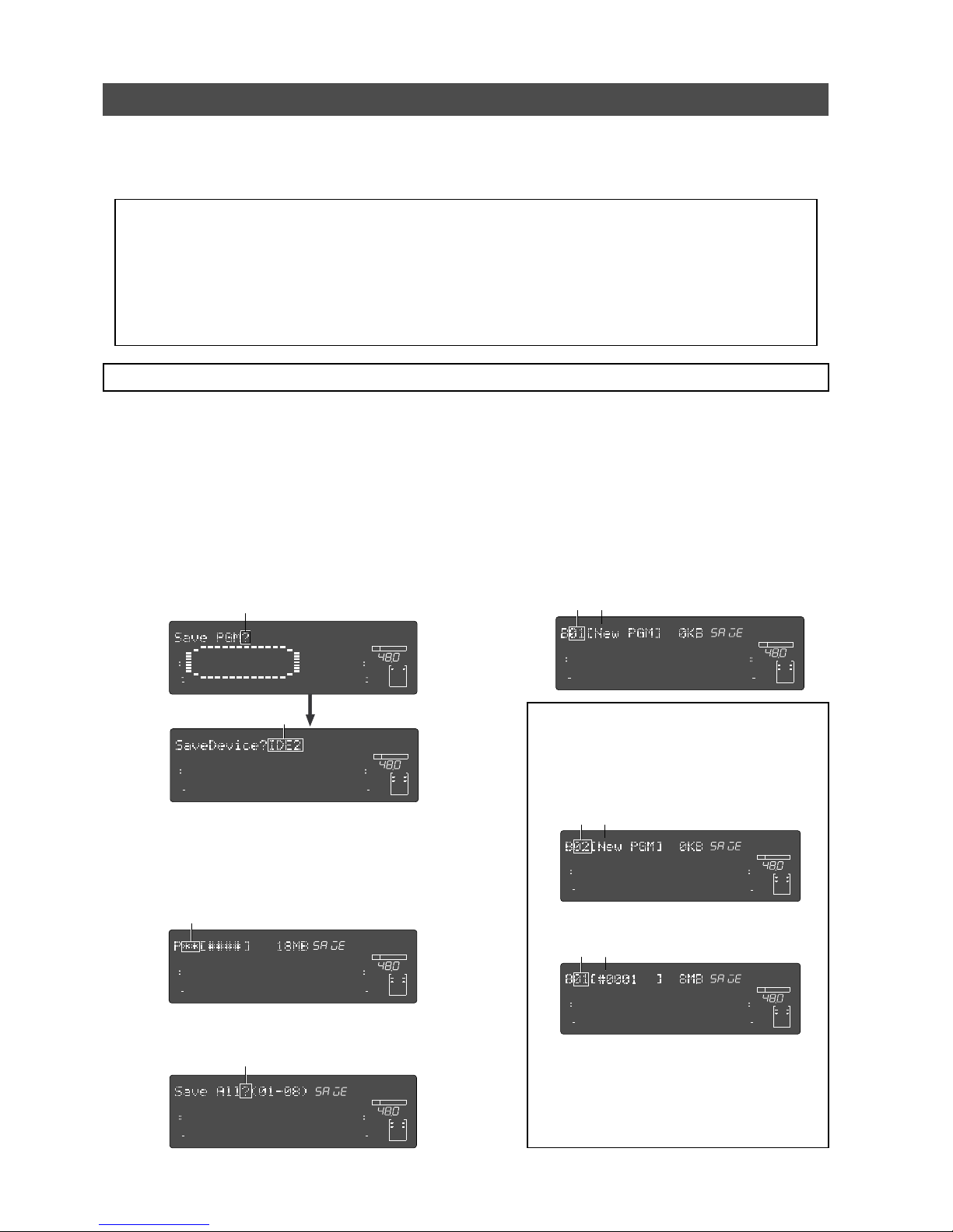
Model D2424LVmkII Reference Manual (Saving and Loading Song Data)
96
Saving and Loading using a CompactFlashTM card or optional E-IDE Hard disk drive
Using the pre-installed CF drive or optional E-IDE hard disk drive, you can save or load FDMS-3 (Fostex Disk
Management System-3) files and WAV (RIFF WAVE) files. If you save program data in the WAV format, you can
not only load it to the unit later but also can play it back or edit it using your computer (plus, the unit can use
a WAV file which is edited by a computer).
<Precautions>
• A backup medium (CompactFlashTM card or E-IDE hard disk) must be formatted in either of the backup mode for
handling FDMS-3 files or the DOS format mode for handling WAV files. So, according to your environment, format
the medium appropriately before using. For details about how to format a backup medium (CompactFlash
TM
card
or E-IDE hard disk), see "Formatting a backup medium (CompactFlash card or optional E-IDE hard disk drive)" on
page 33.
• The optional E-IDE hard disk drive should be installed by an authorized person. Contact your local Fostex dealer
or service station for details. (The pre-installed CF drive is replaced with the E-IDE hard disk drive.)
Saving in FDMS-3 Ver3.0 format
By using a CompactFlashTM card (or E-IDE hard disk) which is formatted to "16bit Backup" or "24bit Backup"
mode, you can save data in FDMS-3 Ver3.0 format. The procedure below shows how to save data to an unused,
formatted CompactFlash
TM
card. (You can save data to the E-IDE hard disk in the similar manner.)
(1) Press the [SETUP] key when the equipment is
stopped.
Go to the SETUP mode.
(2) Turn the Jog dial to select “SavePGM?” (“?”
flashing). Then press the [EXECUTE/YES] key.
The menu to select the device to save the program
on appears. “IDE2” flashes in the default mode.
42
OL
0
30
24
18
12
9
6
3
kHz
24
FS
BIT
SETUP
24
42
OL
0
30
24
18
12
9
6
3
232221201918
17
16151413121110
98765
4
3
2
1
CLOCK
INT
(3) Press the [EXECUTE/YES] key while “IDE2” is
flashing.
A menu appears so you can select the program that
you want to save. The currently selected program
number flashes. The size of the program also
appears.
∞
42
OL
0
30
24
18
12
9
6
3
kHz
24
FS
BIT
SETUP
24
∞
42
OL
0
30
24
18
12
9
6
3
232221201918
17
16151413121110
98765
4
3
2
1
CLOCK
INT
(4) Press the [EXECUTE/YES] key to select the
program that you want to save.
Flashing
Flashing
∞
42
OL
0
30
24
18
12
9
6
3
kHz
24
FS
BIT
SETUP
24
∞
42
OL
0
30
24
18
12
9
6
3
SURE?
232221201918
17
16151413121110
98765
4
3
2
1
CLOCK
INT
∞
42
OL
0
30
24
18
12
9
6
3
kHz
24
FS
BIT
SETUP
24
∞
42
OL
0
30
24
18
12
9
6
3
232221201918
17
16151413121110
98765
4
3
2
1
CLOCK
INT
Flashing
Turn the Jog dial in this state to select individual
programs or select “Save All” (**/**)”.
Flashing
∞
42
OL
0
30
24
18
12
9
6
3
kHz
24
FS
BIT
SETUP
24
∞
42
OL
0
30
24
18
12
9
6
3
SURE?
232221201918
17
16151413121110
98765
4
3
2
1
CLOCK
INT
<Selecting an individual program>
If you select an individual program and press the
[EXECUTE/YES] key, the display shows "B01 [New
PGM]". This indicates that a new program is created
to an unused medium.
<Note>:
If any saved program data exists on a
medium (CF card or E-IDE hard disk), you can
select a desired existing program or [New PGM]
from the list using the jog dial. In the following
example, "B01" exists on the medium and the
program newly created is "B02".
When you select an existing program and
perform program data saving, the new data
overwrites the existing data. If you do not
overwrite the existing data, select "[New PGM]".
∞
42
OL
0
30
24
18
12
9
6
3
kHz
24
FS
BIT
SETUP
24
∞
42
OL
0
30
24
18
12
9
6
3
SURE?
232221201918
17
16151413121110
98765
4
3
2
1
CLOCK
INT
∞
42
OL
0
30
24
18
12
9
6
3
kHz
24
FS
BIT
SETUP
24
∞
42
OL
0
30
24
18
12
9
6
3
SURE?
232221201918
17
16151413121110
98765
4
3
2
1
CLOCK
INT
The selected program data is saved
to the new program.
The selected program data is saved
to the existing program.
Flashing
Flashing
Flashing
Page 97
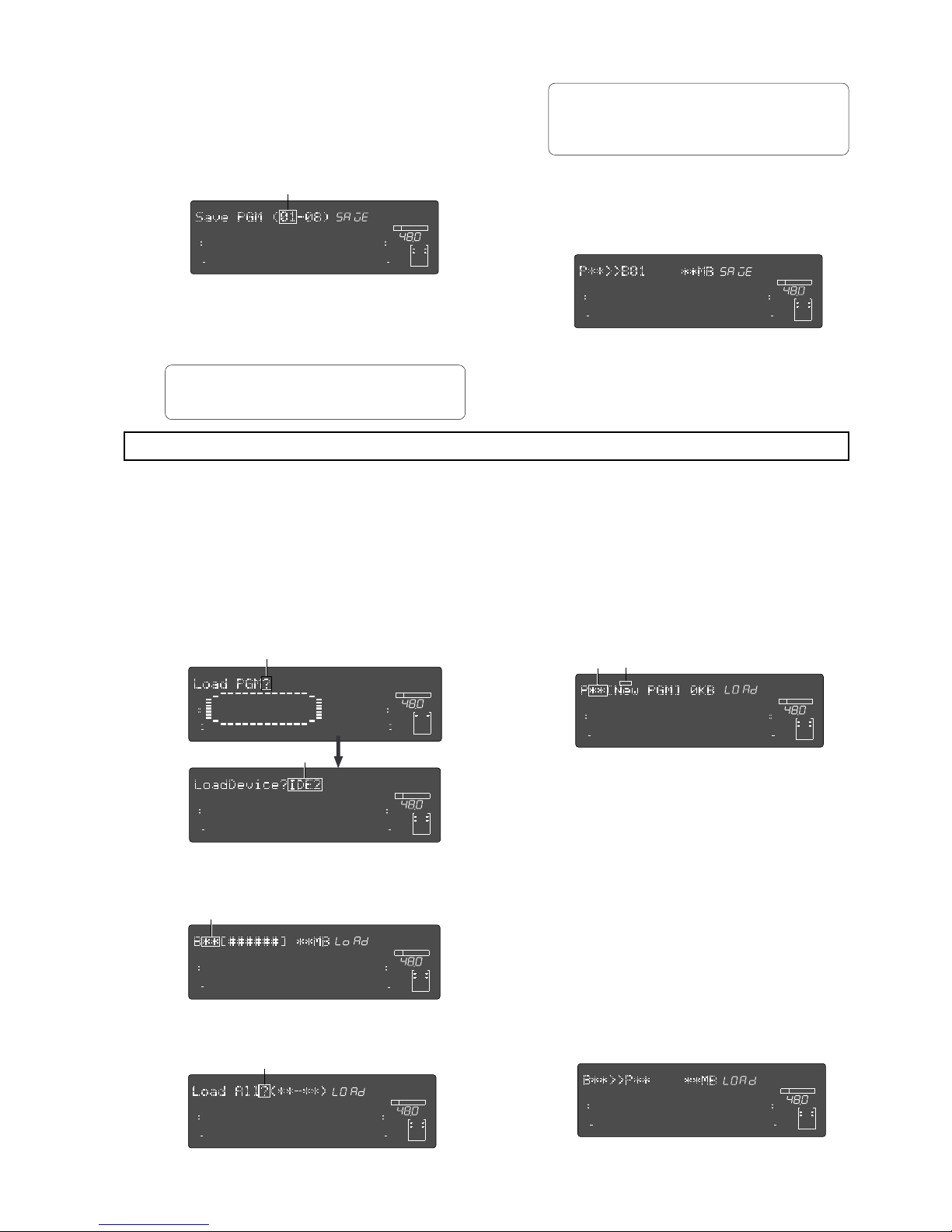
Model D2424LVmkII Reference Manual (Saving and Loading Song Data)
97
(5) Select the load destination program. Then press
the [EXECUTE/YES] key.
Start loading to the load destination program that
you selected. “COMPLETED!” lights up after
successfully loading, and the mode escapes from
the SETUP mode.
Flashing
Flashing
∞
42
OL
0
30
24
18
12
9
6
3
kHz
24
FS
BIT
24
∞
42
OL
0
30
24
18
12
9
6
3
232221201918
17
16151413121110
98765
4
3
2
1
CLOCK
INT
SURE?
∞
42
OL
0
30
24
18
12
9
6
3
kHz
24
FS
BIT
SETUP
24
∞
42
OL
0
30
24
18
12
9
6
3
232221201918
17
16151413121110
98765
4
3
2
1
CLOCK
INT
Loading an FDMS-3 file
(1) Press the [SETUP] key while in the initial menu, to
go to the SETUP mode.
(2) Turn the Jog dial to select “Load PGM?” (“?”
flashes). Then press the [EXECUTE/YES] key.
The menu to select the loading device appears.
“IDE2” is the default setting and the indication
flashes.
42
OL
0
30
24
18
12
9
6
3
kHz
24
FS
BIT
SETUP
24
42
OL
0
30
24
18
12
9
6
3
232221201918
17
16151413121110
98765
4
3
2
1
CLOCK
INT
∞
42
OL
0
30
24
18
12
9
6
3
kHz
24
FS
BIT
SETUP
24
∞
42
OL
0
30
24
18
12
9
6
3
232221201918
17
16151413121110
98765
4
3
2
1
CLOCK
INT
Flashing
Flashing
∞
42
OL
0
30
24
18
12
9
6
3
kHz
24
FS
BIT
SETUP
24
∞
42
OL
0
30
24
18
12
9
6
3
232221201918
17
16151413121110
98765
4
3
2
1
CLOCK
INT
∞
42
OL
0
30
24
18
12
9
6
3
kHz
24
FS
BIT
SETUP
24
∞
42
OL
0
30
24
18
12
9
6
3
232221201918
17
16151413121110
98765
4
3
2
1
CLOCK
INT
You can load FDMS-3 program backup data saved on a CompactFlashTM card (or E-IDE hard disk). In the
following procedure, it is assumed that a CompactFlash
TM
card which contains backup program data is set to
the CF drive.
(3) Press the [EXECUTE/YES] key while “IDE2” is
flashing.
You can now select programs to be loaded.
(5) Select either “New PGM” or an existing program
number. Then press the [EXECUTE/YES] key.
The save process starts. The REMAIN counter (size
to save) starts counting down. (The following is an
example of saving data to backup number “B01”.)
When the data is saved “COMPLETED!” lights up on
the display. Then the system escapes from the
SETUP mode.
∞
42
OL
0
30
24
18
12
9
6
3
kHz
24
FS
BIT
SETUP
24
∞
42
OL
0
30
24
18
12
9
6
3
232221201918
17
16151413121110
98765
4
3
2
1
CLOCK
INT
Flashing
∞
42
OL
0
30
24
18
12
9
6
3
kHz
24
FS
BIT
SETUP
24
∞
42
OL
0
30
24
18
12
9
6
3
232221201918
17
16151413121110
98765
4
3
2
1
CLOCK
INT
<Selecting all (or multiple) programs>
If you select "Save All (01-08)" and press the
[EXECUTE/YES] key, the display shows as below and
you can now select the range of the programs to be
saved. The first program number is flashing. In this
example, eight programs are recorded on the
current drive.
If you want to save all program data, simply press
the [EXECUTE/YES] key when the display shows as
above. To save multiple programs, specify the range
of programs and press the [EXECUTE/YES] key, as
described below.
Example: Saving programs 01 through 04
Rotate the shuttle dial clockwise to flash "08"
and use the jog dial to enter "04".
Example: Saving programs 03 through 06
When "01" is flashing, use the jog dial to enter
"03". Then rotate the shuttle dial clockwise to
flash "08" and use the jog dial to enter "06".
By rotating the jog dial, you can select an individual
backup program, as well as "Load All? (**-**) which
allows you to select multiple programs.
Flashing
(4) Select a program (or programs) to be loaded, and
press the [EXECUTE/YES] key.
You can select a program (or programs) in the
similar manner as selecting a program (or
programs) to be saved. See step (4) of "Saving in
FDMS-3 Ver3.0 format" above for details about how
to select a program (or programs).
After pressing the [EXECUTE/YES] key, the display
shows as below and you can now select the load
destination program. By default, "[New PGM]" is
shown. This option creates a new program for load
destination.
By rotating the jog dial, you can select an existing
program besides "[New PGM]". If you select an
existing program and press the [EXECUTE/YES] key,
the existing program data is overwritten by the
loaded data. If you do not want to overwrite an
existing data, select "[New PGM]".
Flashing
Page 98
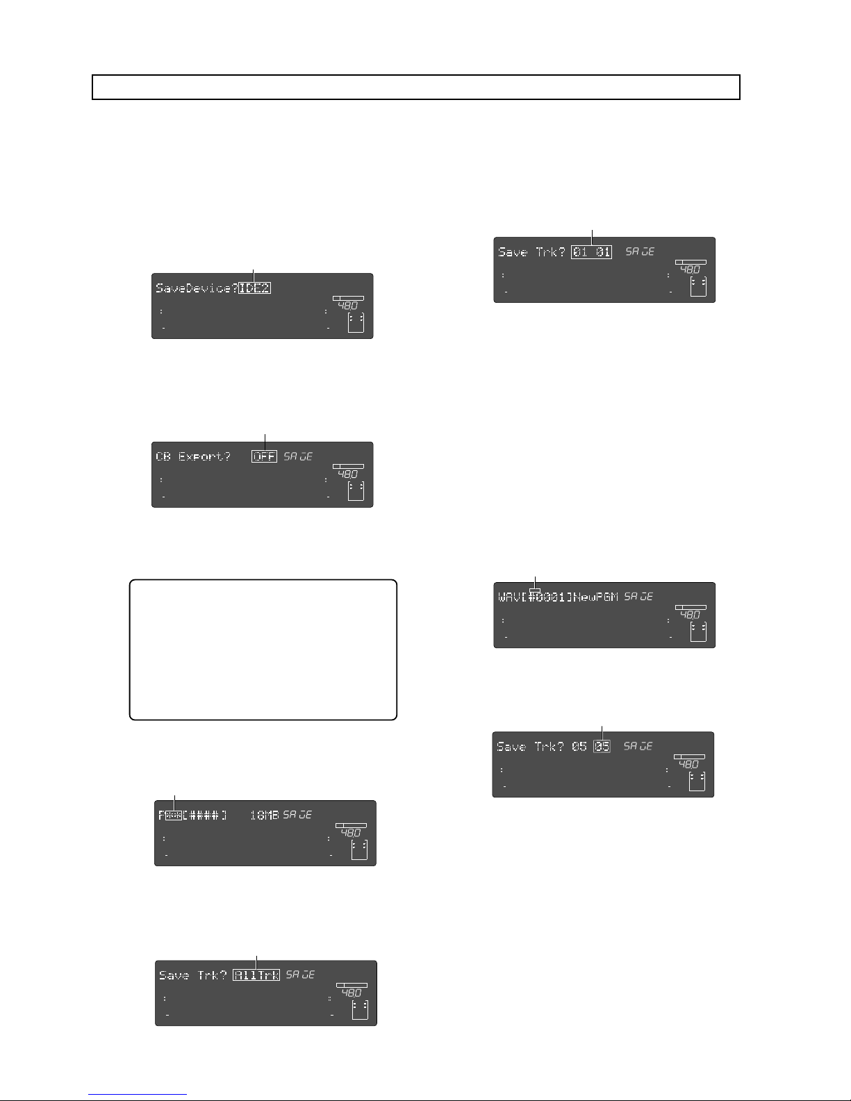
Model D2424LVmkII Reference Manual (Saving and Loading Song Data)
98
(7) Press the [EXECUTE/YES] key.
The display will change for entering the file name
for the WAV file.
Save function in FAT 16
The following procedure shows how to save a program to a FAT16 DOS formatted CompactFlashTM card as a
WAV file. It is assumed that a FAT16 formatted unused CompactFlash
TM
card is set to the CF drive.
(1) The SETUP mode is entered by pressing the
[SETUP] key.
(2) Select “Save PGM?” (“?” flashes) with the Jog dial
and press the [EXECUTE/YES] key.
The currently setup content will flash in the display.
(3) Press the [EXECUTE/YES] key while “IDE2” is
flashing.
The display will change to "CB Export? OFF" ("OFF"
flashes) and ON-OFF of the clip board export can
be setup.
< Please remember! >
When clip board export is set to ON, save is to
be executed only on data within a desired range.
In such a case, the desired range must be
registered by the CLIPBOARD IN and CLIPBOARD
OUT points previous to executing save. For
explanation on registering of CLIPBOARD IN/
OUT points, refer to "Registering of the locate
point (=editing point)" on page 54.
Normally, when saving ABS 0-REC END data,
proceed to the next step while the setup is OFF.
But, under the following condition, save is executed
with the setup ON.
∞
42
OL
0
30
24
18
12
9
6
3
kHz
24
FS
BIT
SETUP
24
∞
42
OL
0
30
24
18
12
9
6
3
232221201918
17
16151413121110
98765
4
3
2
1
CLOCK
INT
Flashing
Flashing
∞
42
OL
0
30
24
18
12
9
6
3
kHz
24
FS
BIT
SETUP
24
∞
42
OL
0
30
24
18
12
9
6
3
232221201918
17
16151413121110
98765
4
3
2
1
CLOCK
INT
(4) Select "OFF" and press the [EXECUTE/YES] key.
The display will change to selecting the program
for saving.
Flashing
∞
42
OL
0
30
24
18
12
9
6
3
kHz
24
FS
BIT
SETUP
24
∞
42
OL
0
30
24
18
12
9
6
3
SURE?
232221201918
17
16151413121110
98765
4
3
2
1
CLOCK
INT
(5) Select the desired program with the Jog dial and
press the [EXECUTE/YES] key.
The display will change to selecting the track to be
saved. In the initial state, "All Trk" will flashes.
If the Jog dial is rotated at this stage, in addition to
"All Trk" (flashing), "01 01" (flashing)-"56 56"
(flashing) can be selected. This function is used
when specifying any desired track and saving it.
(6) After selecting the track, press the [EXECUTE/YES]
key.
If "All Trk" or any desired track was selected, the
display will change to the following.
• When "All Trk" is selected:
The display will change to making a new WAV file
on the card and "SURE?" will flashes.
If you want to save tracks 05 through 24, select "05
05" and go to the next step.
By rotating the jog dial while the display above is
shown, you can select "01 01" through "56 56"
besides "All Trk". The left and right numbers
indicate the beginning and end tracks to be saved
respectively.
Flashing
Flashing
Flashing
∞
42
OL
0
30
24
18
12
9
6
3
kHz
24
FS
BIT
SETUP
24
∞
42
OL
0
30
24
18
12
9
6
3
232221201918
17
16151413121110
98765
4
3
2
1
CLOCK
INT
∞
42
OL
0
30
24
18
12
9
6
3
kHz
24
FS
BIT
SETUP
24
∞
42
OL
0
30
24
18
12
9
6
3
232221201918
17
16151413121110
98765
4
3
2
1
CLOCK
INT
∞
42
OL
0
30
24
18
12
9
6
3
kHz
24
FS
BIT
SETUP
24
∞
42
OL
0
30
24
18
12
9
6
3
SURE?
232221201918
17
16151413121110
98765
4
3
2
1
CLOCK
INT
• If "05-05" is selected:
The Flashing "05 05" will change to flashing only of
the right "05".
Flashing
∞
42
OL
0
30
24
18
12
9
6
3
kHz
24
FS
BIT
SETUP
24
∞
42
OL
0
30
24
18
12
9
6
3
232221201918
17
16151413121110
98765
4
3
2
1
CLOCK
INT
The last track can be selected. After setting to "05
24" by rotating the Jog dial and pressing the
[EXECUTE/YES] key, the display will change the
same as the previous "WAV [#0001] New PGM".
Numbers that can be selected for the right two digits
must be greater than the left two digits (In this
example, either of "05 24").
This means that if the track was specified as "05
05", track 5 only will be saved.
Page 99
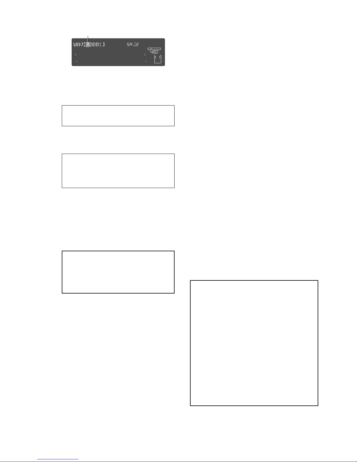
Model D2424LVmkII Reference Manual (Saving and Loading Song Data)
99
< Notes>
• If you attempt to save a WAV file with the same file
name as one already existing on the backup card,
"
Already Exist
" (Same file name already exists) is
displayed and save will not be executed. In this case,
change the WAV file name by the previous Step 7.
• In a card which had been repeatedly saved by
overwriting, access speed could be lowered due to
file fragmentation. We recommend that you use a
card immediately after formatting for backup
purposes.
• When files and folders other than file names
“
******##.WAV
” which can be acknowledged by this
recorder are made on the backup card by using a
computer, in some cases save cannot be completed
as it cannot calculate the accurate remaining capacity
of the backup card. Great care should be taken when
changing file names and making folders by a
computer.
(9) Press the [EXIT/NO] key or [STOP] button.
"COMPLETED!" is extinguished.
• When using a backup card in which a program is
already saved.
If a program is already saved in the backup card,
depending on the remaining capacity, the following
selectable item may be added to the Step 6 Save Method.
These can be selected by rotating the Jog dial.
"Title" & "New PGM" display
There is enough remaining capacity to make a new WAV
file in addition to a WAV file on the card. Press the
[EXECUTE/YES] key and proceed to Step 7. When saved
to the card, this WAV file will be additionally recorded.
Alternate display of "Title" & "New PGM" and"-###MB"
Card capacity is short by the amount of “-###” to be able
to add a new WAV file. Press the [EXECUTE/YES] key
and after display of "Disk Full", "Delete All WAV?" is
displayed, then, press the [EXECUTE/YES] key again, and
it will go to Step 7 for deleting all WAV files on the backup
card. After save, only saved WAV files will be recorded.
"Title" & "###MB" display:
In this instance, the selected WAV file on the backup
card is deleted and there is now enough capacity to
make a WAV file. Press the [EXECUTE/YES] key and "DEL"
(delete of WAV file) will be displayed, and when
[EXECUTE/YES] key is pressed again, it will go to Step 7
for deleting the selected WAV file on the backup card.
After save, the selected WAV file will be replaced as the
new file and recorded on the card.
"Title" & "-###MB" display:
The card is short of capacity by the amount of “-###” to
be able to make a WAV file although the selected WAV
file on the backup card is deleted. If the [EXECUTE/YES]
key is pressed, after display of "Disk Full", "Delete All
WAV?" is displayed, and when the [EXECUTE/YES] key is
pressed again, it will go to Step 7 for deleting all WAV
files on the backup card. After save, only saved WAV
files will be recorded.
If the Jog dial is rotated at the flashing point, any
desired number/symbol/alphabet can be input.
The flashing point can be moved with the Shuttle
dial. Characters which can be input are limited to
the following:
Alphabet capitals (A-Z)
Numbers (0-9)
Symbols (!, #, $, %, &, ', (, ), @, ^, _, -)
Although up to 6 letters can be input for the file
name, some of the letters/symbols/alphabets input
here will be converted as follows.
Alphabet capitals (A-Z) -> No conversion
Alphabet small letters -> (a-z) Converted to capitals
Numerals (0-9) -> No conversion
Symbols -> No conversion
Other symbols -> Under bar is converted to “_”
(8) After inputting a file name, press the [EXECUTE/
YES] key.
Save will be executed and the following displayed.
During save, the capacity display will continue to
count down.
At completion of save, the display returns to the
original time base and "COMPLETED!" will light.
<Note>:
If you attempt to save a WAV file with
the same name as an existing WAV file on the
backup card, "
Already Exist
" (The same file
already exists) will be displayed and save cannot
be executed. For details, refer to the later “Using
a backup card in which a program is already
saved.”
Flashing
∞
42
OL
0
30
24
18
12
9
6
3
kHz
24
FS
BIT
SETUP
24
∞
42
OL
0
30
24
18
12
9
6
3
232221201918
17
16151413121110
98765
4
3
2
1
CLOCK
INT
Page 100
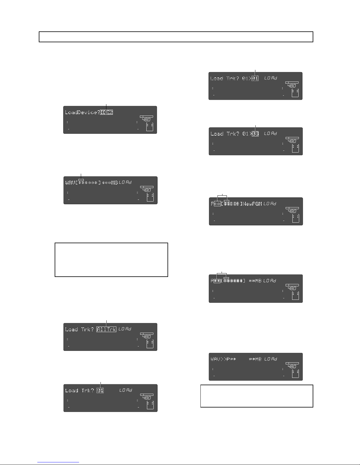
Model D2424LVmkII Reference Manual (Saving and Loading Song Data)
100
The following procedure shows how to save a program to a FAT16 DOS formatted CompactFlashTM card as a
WAV file. It is assumed that a FAT16 formatted unused CompactFlash
TM
card is set to the CF drive.
(1) Enter the SETUP mode by pressing the [SETUP] key.
(2) Select “Load PGM?” (“?” flashes) with the Jog dial
and press the [EXECUTE/YES] key.
The currently set content will be displayed
(flashing).
<Note>:
File names other than “
******##.WAV
”
cannot be acknowledged nor loaded by this
recorder. WAV files with the beginning 6 letters
of the file name will be individually
acknowledged and can be selected.
(5) Select WAV file, then press the [EXECUTE/YES] key.
The display will change to selecting the track to be
loaded. "All Trk" will flashes.
If the Jog dial is rotated at this stage, "01-56" (mono
tracks) can also be selected in addition to "All Trk".
(4) Select the WAV file to be loaded with the Jog dial.
If a multiple number of WAV files with different
file names (Beginning 6 letters) have been saved,
the WAV file names (beginning 6 letters) and
capacity will be sequentially displayed.
(3) Press the [EXECUTE/YES] key while “IDE2” is
flashing.
The WAV file name and its capacity is displayed
and "[ ]" will flash at the same time.
∞
42
OL
0
30
24
18
12
9
6
3
kHz
24
FS
BIT
SETUP
24
∞
42
OL
0
30
24
18
12
9
6
3
232221201918
17
16151413121110
98765
4
3
2
1
CLOCK
INT
Select the mono track (01-56) then press the
[EXECUTE/YES] key. A menu appears to select the
load destination track.
Flashing
Flashing
Flashing
∞
42
OL
0
30
24
18
12
9
6
3
kHz
24
FS
BIT
SETUP
24
∞
42
OL
0
30
24
18
12
9
6
3
232221201918
17
16151413121110
98765
4
3
2
1
CLOCK
INT
∞
42
OL
0
30
24
18
12
9
6
3
kHz
24
FS
BIT
SETUP
24
∞
42
OL
0
30
24
18
12
9
6
3
SURE?
232221201918
17
16151413121110
98765
4
3
2
1
CLOCK
INT
Flashing
∞
42
OL
0
30
24
18
12
9
6
3
kHz
24
FS
BIT
SETUP
24
∞
42
OL
0
30
24
18
12
9
6
3
232221201918
17
16151413121110
98765
4
3
2
1
CLOCK
INT
(7) After selecting the program to load, press the
[EXECUTE/YES] key.
The following will be displayed during load.
As load progresses, the capacity indication will
count down. Upon completion of the load, the
display will return to the original time base and
"COMPLETED!" is displayed.
(6) Select the track, then press the [EXECUTE/YES] key.
It will change to the display for compiling a new
program (“New PGM”) in the objective track for
loading.
When the Jog dial is rotated while in this state, the
program in the objective track for loading can be
selected, and its recording capacity will also be
shown. When loading by selecting an existing
program, loading can be done in parallel with
erasing (super scripting) this existing program.
Flashing
Flashing
As an example, if the track is setup as shown below,
data in track 1 will be loaded in track 8.
∞
42
OL
0
30
24
18
12
9
6
3
kHz
24
FS
BIT
SETUP
24
∞
42
OL
0
30
24
18
12
9
6
3
232221201918
17
16151413121110
98765
4
3
2
1
CLOCK
INT
∞
42
OL
0
30
24
18
12
9
6
3
kHz
24
FS
BIT
SETUP
24
∞
42
OL
0
30
24
18
12
9
6
3
232221201918
17
16151413121110
98765
4
3
2
1
CLOCK
INT
Flashing
Flashing
∞
42
OL
0
30
24
18
12
9
6
3
kHz
24
FS
BIT
24
∞
42
OL
0
30
24
18
12
9
6
3
SURE?
232221201918
17
16151413121110
98765
4
3
2
1
CLOCK
INT
∞
42
OL
0
30
24
18
12
9
6
3
kHz
24
FS
BIT
SETUP
24
∞
42
OL
0
30
24
18
12
9
6
3
SURE?
232221201918
17
16151413121110
98765
4
3
2
1
CLOCK
INT
∞
42
OL
0
30
24
18
12
9
6
3
kHz
24
FS
BIT
SETUP
24
∞
42
OL
0
30
24
18
12
9
6
3
232221201918
17
16151413121110
98765
4
3
2
1
CLOCK
INT
<Note>
: The title of the loaded program will be
replaced by the WAV file name (beginning 6
letters) which is loaded.
Load function in FAT 16
Turn the Jog dial in this state to select the load
destination track (01-56 are selectable with the
above example).
 Loading...