

Page 1
S e r v i c e M a n u a l
Solo Plus
Units 2001
Page 2
Page 3
PART 1A
Wall Mount Units
Ceiling Mounted Units
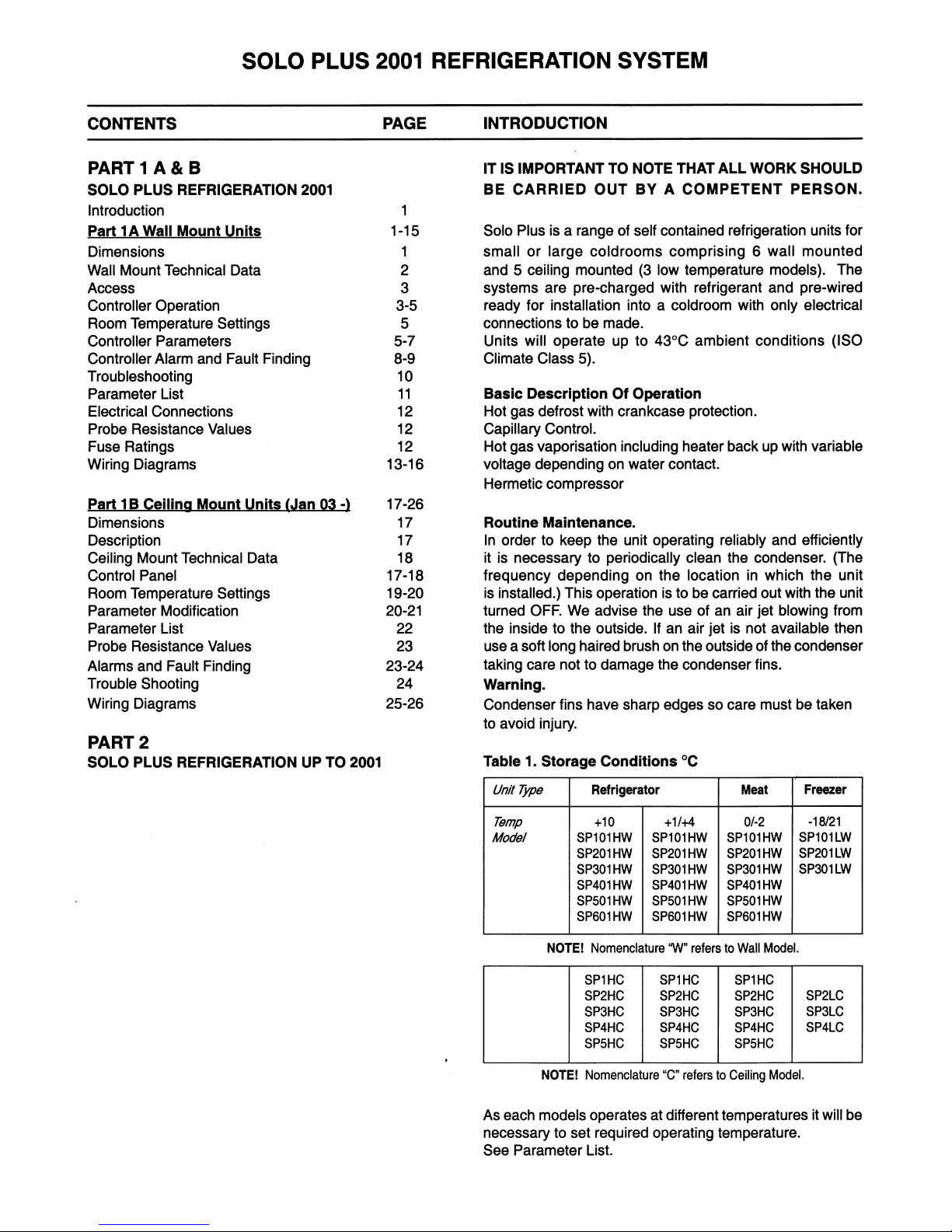
DIMENSIONS
N
J
H
I
MODEL CONDENSER UNIT EVAPORATOR UNIT PLUG SIZE CUT-OUT SIZE
A x B x C (mm) G x E x F (mm) W x H (mm) W X H (mm)
H x J x K (mm) I x M x N (mm)
SP 1 HC 620 x 719 x 357 545 x 150 x 332 545 x 332 550 x 337
SP 2 H & LC 620 x 719 x 357 545 x 150 x 332 545 x 332 550 x 337
SP 3 H & LC 820 x 809 x 390 745 x 150 x 332 745 x 332 750 x 337
SP 4 HC 820 x 809 x 390 745 x 150 x 332 745 x 332 750 x 337
SP 4 LC 820 x 929 x 427 745 x 220 x 452 745 x 452 750 x 458
SP 5 HC 820 x 929 x 427 745 x 220 x 452 745 x 452 750 x 458
1
Mod. A B C D E F G
SP101LW, SP101HW
735 264 790 400 280 510 368
SP201HW, SP301HW
SP201LW, SP401HW
830 264 790 620 280 510 585
SP501HW
SP301LW, SP601HW 830 364 982 620 350 632 585
Page 4
2
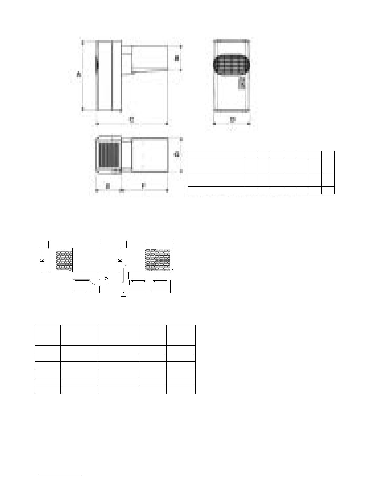
2. SOLO PLUS TECHNICAL DATA
Foster Nom. HP Cut Out HP Cut In Suction Valve Noise Heat Rejected RoomVent 32°C Ambient 43°C Ambient Air Air Vol Electrical Nominal Defrost Condensate Net Gross
Model No. HP Press Bar Press Bar Press Bar Level dBa Max Watts @ 32°C
m
3
/ h # Watts Room Cap Watts Room Cap Throw mts m
3
/ h
Volts
Phase
Hz
Amps Watts Type Vaporisation Wt. Kg Wt. Kg
NOTE: The condenser fan pressure stat fitted on Low Ambient units should be set at 17bar with a 1.5bar differential, this applies to high and low temperature models.
SP 101HW 0.375 28 23 ------ 58 1900 700 1300 11 1160 8 4 600 230 1 50 3.9 600 Hot Gas Auto 53 74
SP 201HW 0.5 28 23 ------ 60 2050 700 1450 13 1200 11 4 600 230 1 50 5.5 600 Hot Gas Auto 56 77
SP 301HW 0.75 28 23 ------ 60 2700 700 1800 16 1550 14 4 600 230 1 50 5.6 900 Hot Gas Auto 64 85
SP 401 HW 0.75 28 23 ------ 60 3650 1400 2550 25 2200 20 4 1200 230 1 50 7 1100 Hot Gas Auto 80 110
SP 501HW 1 28 23 ------ 62 5100 1400 3100 33 2700 27 4 1200 400 3 50 5.2 1800 Hot Gas Auto 80 110
SP 601HW 1.5 28 23 ------ 63 6900 1500 4700 58 4000 48 9.5 1800 400 3 50 5.9 2200 Hot Gas Auto 100 135
STORAGE TEMP +10°C
Foster Ref Qty Capillary Size
Model No. Gas Grms No. x Dia x Len
SP 101HW R404A 0.67 1 x 1.5 x 2500
SP 201HW R404A 0.67 1 x 1.5 x 2500
SP 301HW R404A 0.64 1 x 1.8 x 2000
SP 401HW R404A 1.10 1 x 2.0 x 2900
SP 501HW R404A 0.88 2 x 1.8 x 2500
SP 601HW R404A 1.11 2 x 2.0 x 2000
Foster Nom. HP Cut Out HP Cut In Suction Valve Noise Heat Rejected RoomVent 32°C Ambient 43°C Ambient Air Air Vol Electrical Nominal Defrost Condensate Net Gross
Model No. HP Press Bar Press Bar Press Bar Level dBa Max Watts @ 32°C
m
3
/ h # Watts Room Cap Watts Room Cap Throw mts m
3
/ h
Volts
Phase
Hz
Amps Watts Type Vaporisation Wt. Kg Wt. Kg
SP 101HW 0.375 28 23 ------ 58 1650 700 1050 7 900 6 4 600 230 1 50 3.9 600 Hot Gas Auto 53 74
SP 201HW 0.5 28 23 ------ 60 1756 700 1150 9 1050 7 4 600 230 1 50 5.5 600 Hot Gas Auto 56 77
SP 301HW 0.75 28 23 ------ 60 2356 700 1450 13 1300 10 4 600 230 1 50 5.6 900 Hot Gas Auto 64 85
SP 401 HW 0.75 28 23 ------ 60 3000 1400 1900 20 1600 14 4 1200 230 1 50 7 1100 Hot Gas Auto 80 110
SP 501HW 1 28 23 ------ 62 4500 1400 2700 30 2350 24 4 1200 400 3 50 5.2 1800 Hot Gas Auto 80 110
SP 601HW 1.5 28 23 ------ 63 6300 1500 4100 50 3300 35 9.5 1800 400 3 50 5.9 2200 Hot Gas Auto 100 135
Foster Nom. HP Cut Out HP Cut In Suction Valve Noise Heat Rejected RoomVent 32°C Ambient 43°C Ambient Air Air Vol Electrical Nominal Defrost Condensate Net Gross
Model No. HP Press Bar Press Bar Press Bar Level dBa Max Watts @ 32°C
m
3
/ h # Watts Room Cap Watts Room Cap Throw mts m
3
/ h
Volts
Phase
Hz
Amps Watts Type Vaporisation Wt. Kg Wt. Kg
SP 101HW 0.375 28 23 ------ 58 1450 700 850 6 750 5 4 600 230 1 50 3.9 600 Hot Gas Auto 53 74
SP 201HW 0.5 28 23 ------ 60 1550 700 950 7 850 6 4 600 230 1 50 5.5 600 Hot Gas Auto 56 77
SP 301HW 0.75 28 23 ------ 60 2100 700 1300 11 1200 9 4 600 230 1 50 5.6 900 Hot Gas Auto 64 85
SP 401 HW 0.75 28 23 ------ 60 2800 1400 1700 15 1400 11 4 1200 230 1 50 7 1100 Hot Gas Auto 80 110
SP 501HW 1 28 23 ------ 62 4100 1400 2300 21 2000 17 4 1200 400 3 50 5.2 1800 Hot Gas Auto 80 110
SP 601HW 1.5 28 23 ------ 63 5550 1500 3350 36 2800 26 9.5 1800 400 3 50 5.9 2200 Hot Gas Auto 100 135
Foster Nom. HP Cut Out HP Cut In Suction Valve Noise Heat Rejected RoomVent 32°C Ambient 43°C Ambient Air Air Vol Electrical Nominal Defrost Condensate Net Gross
Model No. HP Press Bar Press Bar Press Bar Level dBa Max Watts @ 32°C
m
3
/ h # Watts Room Cap Watts Room Cap Throw mts m
3
/ h
Volts
Phase
Hz
Amps Watts Type Vaporisation Wt. Kg Wt. Kg
SP 101LW 1.25 28 23 2.5 62 1950 700 1050 7 850 5 4 600 230 1 50 5.2 900 Hot Gas Auto 64 85
SP 201LW 1.5 28 23 2.5 63 3200 1400 1700 14 1400 10 4 1200 400 3 50 4.3 1500 Hot Gas Auto 80 110
SP 301LW 2.2 28 23 2.5 63 4440 1500 2700 28 2250 20 9.5 1800 400 3 50 4.5 1700 Hot Gas Auto 105 140
Foster Ref Qty Capillary Size
Model No. Gas Grms No. x Dia x Len
SP 101HW R404A 0.67 1 x 1.5 x 2500
SP 201HW R404A 0.67 1 x 1.5 x 2500
SP 301HW R404A 0.64 1 x 1.8 x 2000
SP 401HW R404A 1.10 1 x 2.0 x 2900
SP 501HW R404A 0.88 2 x 1.8 x 2500
SP 601HW R404A 1.11 2 x 2.0 x 2000
Foster Ref Qty Capillary Size
Model No. Gas Grms No. x Dia x Len
SP 101HW R404A 0.67 1 x 1.5 x 2500
SP 201HW R404A 0.67 1 x 1.5 x 2500
SP 301HW R404A 0.64 1 x 1.8 x 2000
SP 401HW R404A 1.10 1 x 2.0 x 2900
SP 501HW R404A 0.88 2 x 1.8 x 2500
SP 601HW R404A 1.11 2 x 2.0 x 2000
STORAGE TEMP +10°C STORAGE TEMP +1/4°C STORAGE TEMP 0/-2°C
STORAGE TEMP +1/4°C
STORAGE TEMP 0/-2°C
STORAGE TEMP -18/-21°C
Foster Ref Qty Capillary Size
Model No. Gas Grms No. x Dia x Len
SP 101LW R404A 0.53 1 x 1.5 x 2500
SP 201LW R404A 0.84 1 x 1.8 x 2500
SP 301LW R404A 1.13 2 x 1.6 x 2800
STORAGE TEMP -18/-21°C
Page 5
3. ACCESS TO THE UNIT COMPARTMENT / EVAPORATOR HOUSING
WALL MODEL
Front Panel: Grasp each side of the front panel and “pull forward” releasing it from the spring clips located
down each edge,it may be necessary to separate the front panel from the main body using a flat
blade screwdriver and gently ease away.
Condenser Fan After removing the front panel “pull upwards” the fan housing assembly releasing it from
Assembly: the 4 “spring clips” located in each corner, it may be necessary to separate the fan housing
assembly from the main body using a flat blade screwdriver and gently ease away.
Evaporator Fan Remove the screw securing the drain tube to the drip tray and remover the drain tube.
Remove the four screws securing the drain pan and remove.
Remove the three remaining screws securing the side panel and remove it allowing access into
the evaporator fan assembly.
4. CONTROLLER OPERATION
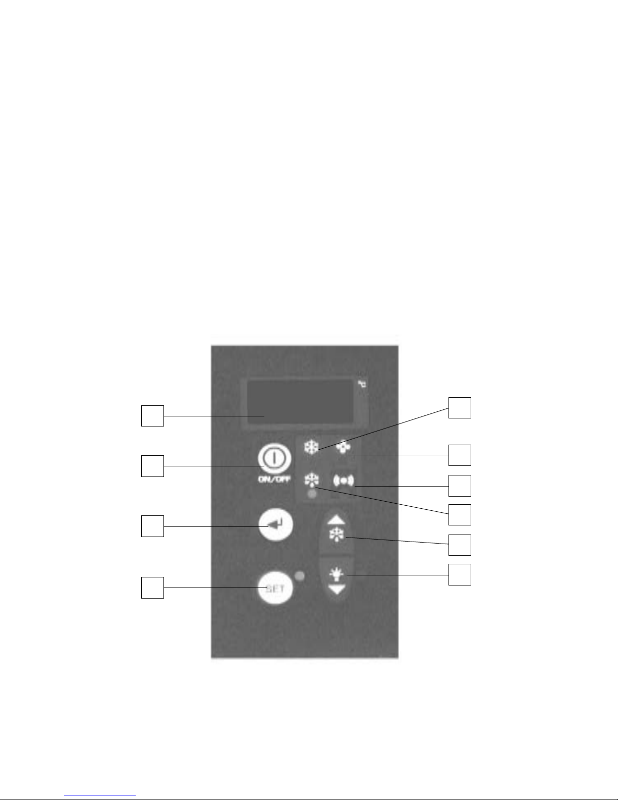
DESCRIPTION OF ELECTRONIC PANEL
5
9
10
6
1
2
4
3
8
7
3
Page 6
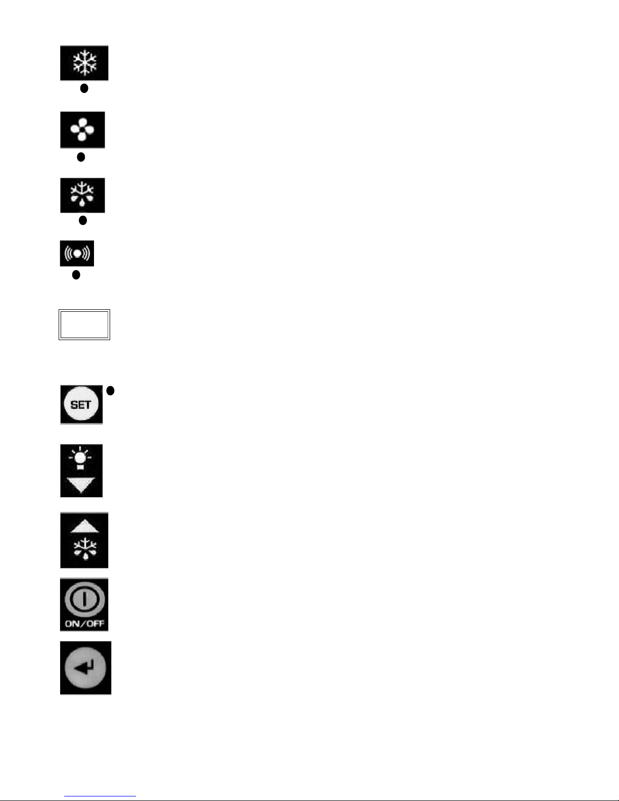
1) CONTROL LED (Green):
Lit: Compressor running, unit is refrigerating. FLASHING: Compressor is in start delay mode
(waiting for signal to start) OFF: Compressor is OFF. Room is down to set temperature.
2) CONTROL LED (Green):
LIT: Evaporator fan(s) running. FLASHING: Evaporator fan(s) in start delay mode (waiting for
signal to start ) OFF: Evaporator fan (s) OFF
3) Control LED (Yellow):
LIT: Unit in defrost mode (auto or manual)
Flashing Evaporator drip time with compressor and evaporator fan off.
4) ALARM LED (Red):
LIT: Alarm is active – see separate ALARMS section. OFF: Unit is functioning normally
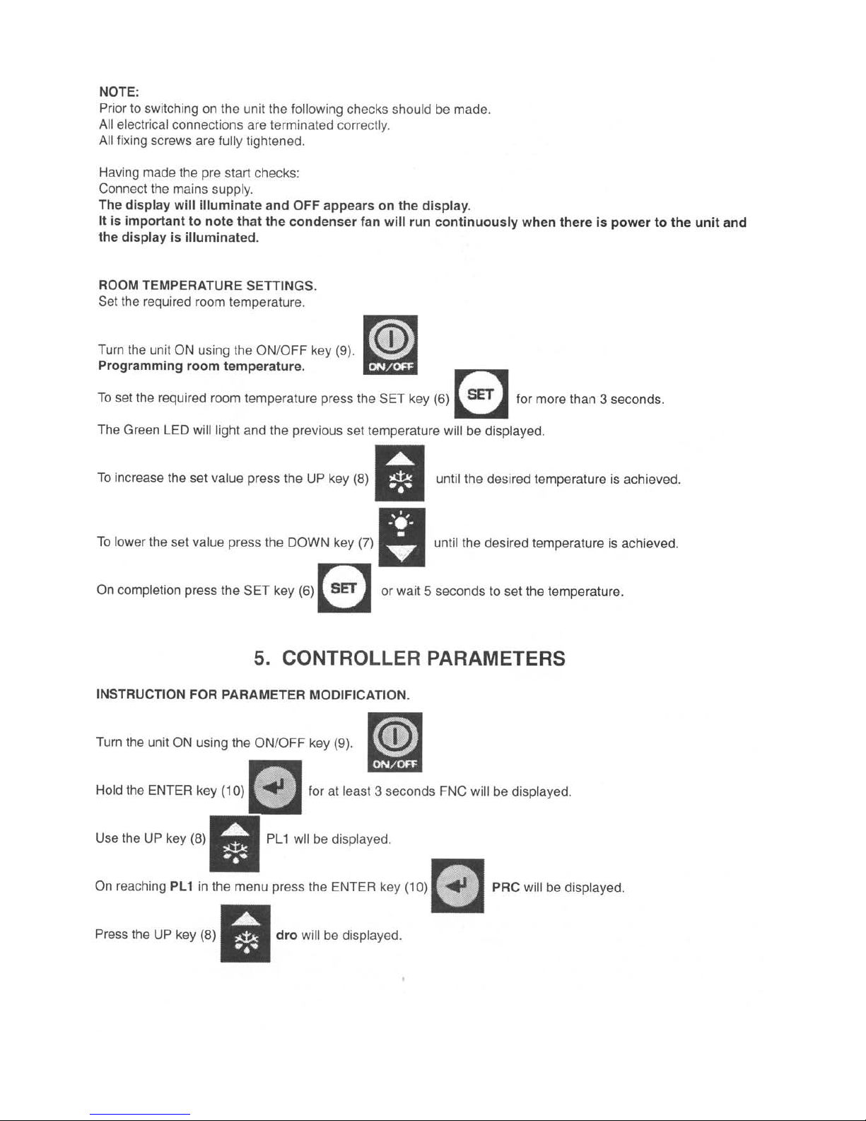
5) DISPLAY:
When connected to the mains the display will read OFF indicating the condition of the unit. By
pressing the ON/OFF key for 3 seconds the unit will turn ON and display the room temperature.
During programming mode the various parameters will be displayed and during alarm mode an
alarm code will be displayed.
6) SET/ESC KEY:
Pressed for 3 seconds, the led is lit and setting of required room temperature is enabled. During
programming it is used to pass from a sub menu to an upper one.
7) DOWN/ ROOM LIGHT KEY:
During programming mode or setting of room temperature it serves to reduce the display value.
At other times it serves to control the room light.
8) DEFROST/ UP KEY:
By pressing for more than 4 seconds it activates a manual defrost. During programming mode or
setting of room temperature it serves to increase the displayed value.
9) ON/OFF KEY:
To turn the unit ON or OFF press and hold for more than 3 seconds.
10) ENTER KEY:
Permits access to the programming menu and passage to the sub menu. Access to this programming
mode should be by qualified persons only.
°C
4
Page 7
5
Page 8
6
Page 9
7
Page 10

8
CONTROLLER ALARMS AND FAULT FINDING.
When an alarm condition occurs the unit will display an alarm code ERR (this will differ according to the nature of
the alarm):
• Alarm LED will illuminate (4)
• Buzzer will sound (if remote alarm is fitted)
• The alarm relay (for remote alarms) will be energised.
The pressing of any key will mute the alarm buzzer.
When the alarm is muted the LED will continue to flash for as long as the alarm condition persists.
To display the alarm code it is necessary to enter the alarm menu:
Press the ENTER key (10) for more than three seconds. FnC will be displayed. Press the DEFROST/UP key (8)
until AL is displayed and then press ENTER (10). At this point the alarm code will be displayed indicating the nature
of the alarm.
High Temperature Alarm (HI)
The red LED, buzzer and remote alarm relay are activated; the alarm code HI is displayed in the Alarm Menu.
The cause can be:
• Product to warm
• Excessive door openings
• Excessive product load
• Unit malfunction
Low Temperature Alarm (LI)
The red LED, buzzer and remote alarm relay are activated; the alarm code LI is displayed in the Alarm Menu.
The cause can be:
• Malfunction of the electronic controller
High Pressure Alarm (EO)
Each time the pressure switch trips, the buzzer and red LED are activated. If more than ten trips occur during a
1-hour period then the unit will shut down automatically. The remote relay will be activated and the label
ERR will
flash on the display alternating with the room temperature. The alarm code EO is displayed in the Alarm Menu.
The cause can be:
• Dirty condenser
• Condenser fan not running
• Front cover not fitted
• Obstructed condenser air inlet
• Obstructed condenser air outlet
• Inadequate ventilation
Voltage Monitor Alarm (E8 – only when fitted as an option)
The optional voltage monitor is an electronic device that checks the units’ electrical supply. Should the voltage vary
by +/- 12% the unit will shut down for a period of 6 minutes (not adjustable) before attempting to re-start automatically
providing the voltage has returned to within limits. The red LED, buzzer and remote alarm relay are activated; the
label ERR will flash on the display alternating with the room temperature. The alarm code E8 is displayed in the
alarm menu.
WARNING: if the Voltage monitor is fitted it is important to note that on start up it has a time delay of seven minutes,
during this period the power should be on with the controller in the OFF position.
Room Sensor Fault (E1)
The red LED, buzzer and remote alarm relay are activated; the label ERR will flash on the display alternating with
the room temperature: alarm code E1 in the alarm menu.
Possible causes are:
•
Faulty room sensor.
• Room sensor terminals badly connected.
Page 11

9
Defrost sensor fault (E2)
The red LED, buzzer and remote alarm relay are activated; the label ERR will flash on the display alternating with
the room temperature: alarm code E2 in the alarm menu.
Possible causes are:
•
Faulty defrost sensor
• Defrost sensor terminals badly connected.
Condenser Sensor Fault (4)
The red LED, buzzer and remote alarm relay are activated; the label
ERR will flash on the display alternating with
the room temperature: alarm code E4 in the alarm menu.
Possible causes are:
•
Faulty condenser sensor
• Condenser sensor terminals badly connected.
Condenser Temperature Alarm (H4)
If the condensing temperature exceeds the factory pre set value (not adjustable) the red LED, buzzer and remote
alarm relay are activated: The alarm code H4 is displayed in the alarm menu.
Possible causes are:
•
Dirty condenser
• Condenser fan not running
• Front cover not fitted
• Obstructed condenser air inlet
TROUBLE SHOOTING
1) Compressor stops. There is an internal over temperature device (Klixon) that stops the compressor each time the
admissible temperature of the motor windings is exceeded.
Possible causes are:
• Insufficient ventilation to the compressor
• Mains voltage anomaly
• Faulty condenser fan
The device will re-set automatically when the windings cool down.
2) Formation of ice on evaporator coil impeding airflow.
Possible causes are:
• Excessive door openings
• Door left open for long periods
• Evaporator fan/s faulty
• Door switch faulty (if fitted)
• Faulty defrost heater (if fitted)
• Faulty hot gas solenoid valve (if fitted)
• Pre set defrost routine not sufficient to clear evaporator of ice build up.
• Decrease the time interval between defrosts.
3) Display does not illuminate.
• Is their power to the unit?
• Is the mains cable connected correctly?
• Have the fuses in the electrical panel blown?
Page 12
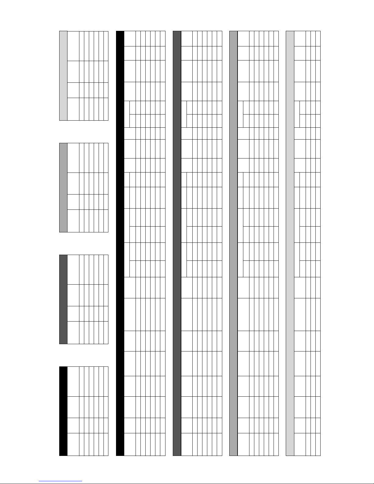
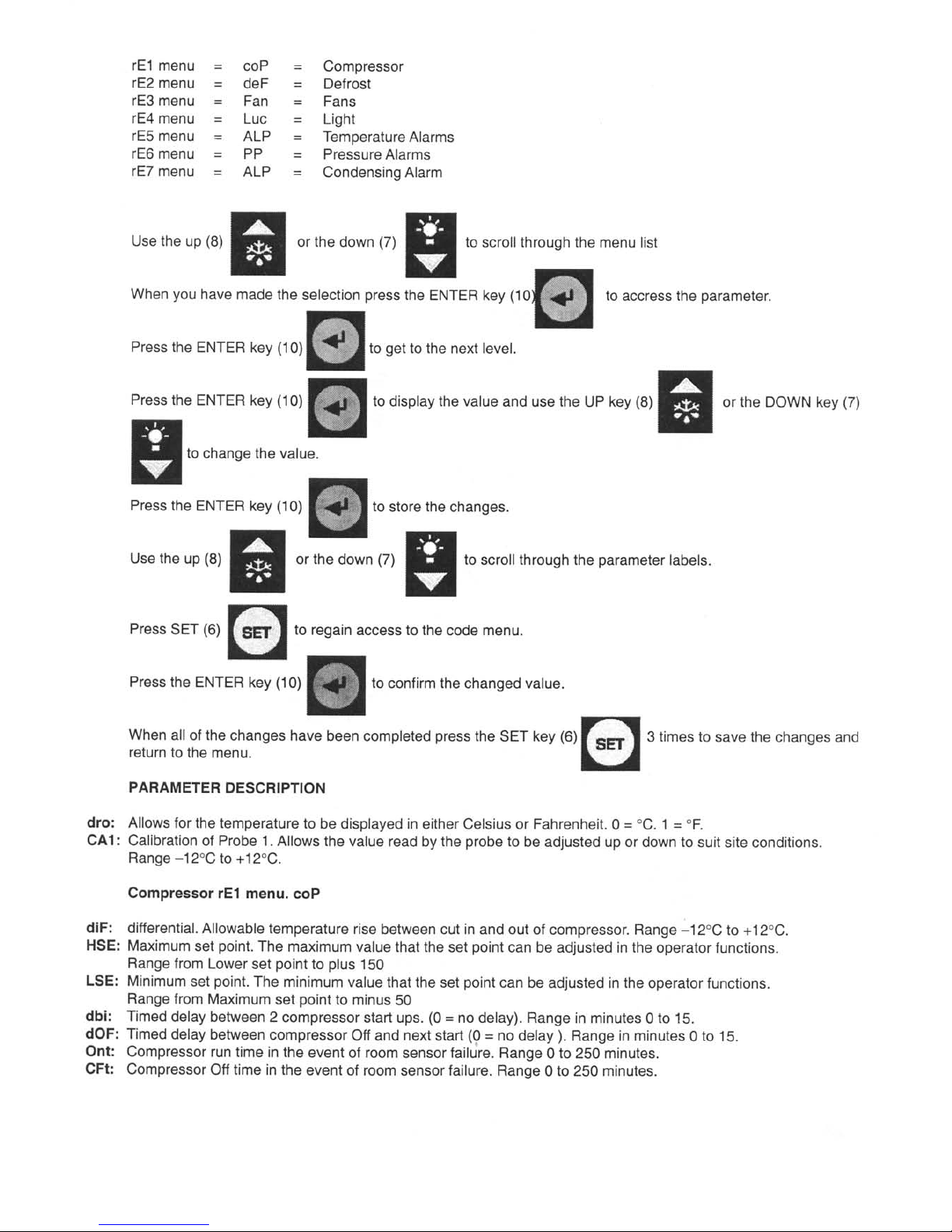
7. PARAMETER LIST
10
Medium Low
Label Description
Unit of
Range
Hot gas Hot gas
measure defrost defrost
dro Display Readout °C or °F ( 0=°C. 1=°F) Flag 0 or 1 0 0
CA1 Calibration of room sensor °C -12 to +12 0 0
Compressor rE1 menu. coP
diF Differential °C/1 2 2 2
HSE Maximum set point °C/1 LSE to 150 10 -15
LSE Minimum set point °C/1 -50 to HSE -5 -25
dbi Time delay between 2 compressor starts Minutes 0 to 15 2 2
dOF Time delay between compressor OFF and next start Minutes 0 to 15 2 2
Ont Compressor ON time if room sensor fails Minutes 0 to 250 10 10
OFt Compressor OFF time if room sensor fails Minutes 0 to 250 20 20
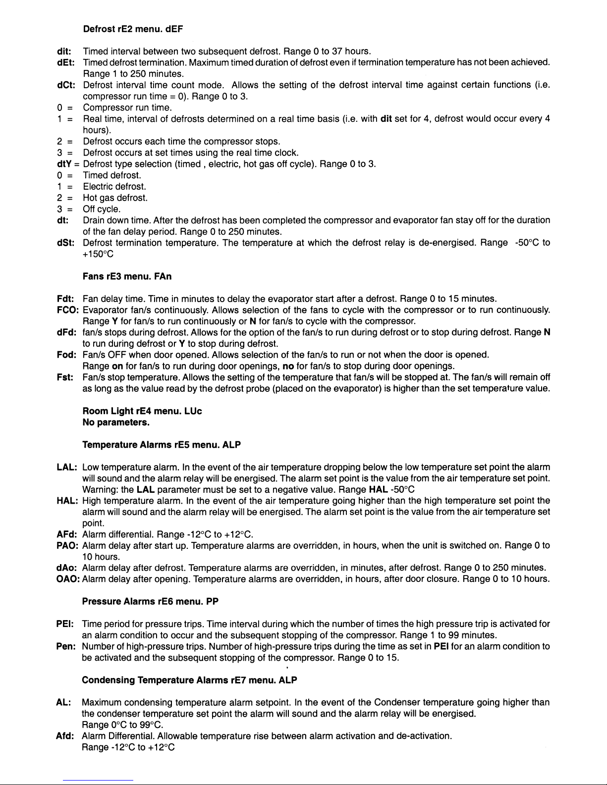
Defrost rE2 menu. dEF
dit Time interval between 2 defrosts Hour 0 to 31 3 3
dEt Defrost time override Minutes 1 to 250 20 20
dCt Defrost interval time count mode Number 0 to 3 0 0
0 = compressor run time
1 = unit run time
2 = each time compressor stops
3 = determined on a real time basis
dtY Defrost type selection Number 0 to 3 2 2
0 = Timed defrost
1 = Electric defrost
2 = hot gas
3 = Off cycle
dt Drain down time Minutes 0 to 250 2 2
dSt Defrost termination temperature °C/1 -50 to 150 15 15
Evaporator Fans rE3 menu. FAn
Fdt Fan delay time Minutes 0 to 15 3 3
FCO Evaporator fan/s run with compressor Flag n / y n n
dFd Fan/s stops during defrost Flag n / y y y
Fod Fan/s off when door opened Flag on/off on on
FSt Fan stop temperature °C/1 -50 to 150 50 50
Room Light rE4 menu. LUc
No parameters
Temperature Alarms rE5 menu. ALP
LAL Low temperature alarm °C/1 -50 to HAL -5 -5
HAL High temperature alarm °C/1 LAL to 150 5 5
AFd Alarm differential °C/1 -12 to 12 2 2
PAO Alarm delay after start-up Hour 0 to 10 3 6
dAo Alarm delay after defrost Minutes 0 to 250 60 60
OAO Alarm delay after door opening Hour 0 to 10 1 1
Pressure alarms rE6 menu. PP
PEi Time period for pressure trips Minutes 1 to 99 60 60
Pen Numbers of pressure trips Number 0 to 15 10 10
Condensing temperature alarms rE7 menu. ALP
HAL Maximum condensing temperature alarm setpoint °C/1 0 to 99 55 55
AFd Alarm differential °C/1 -12 to 12 2 2
Page 13
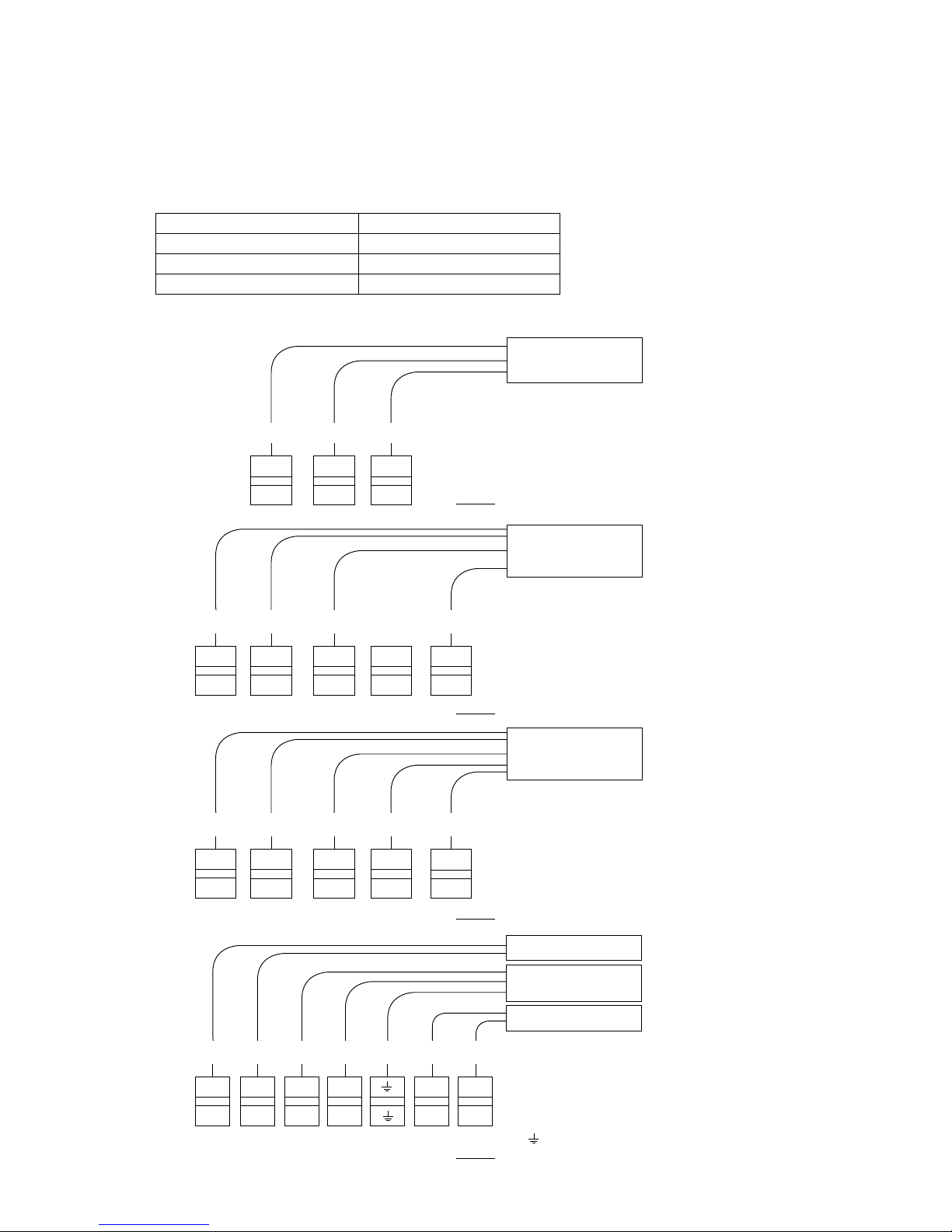
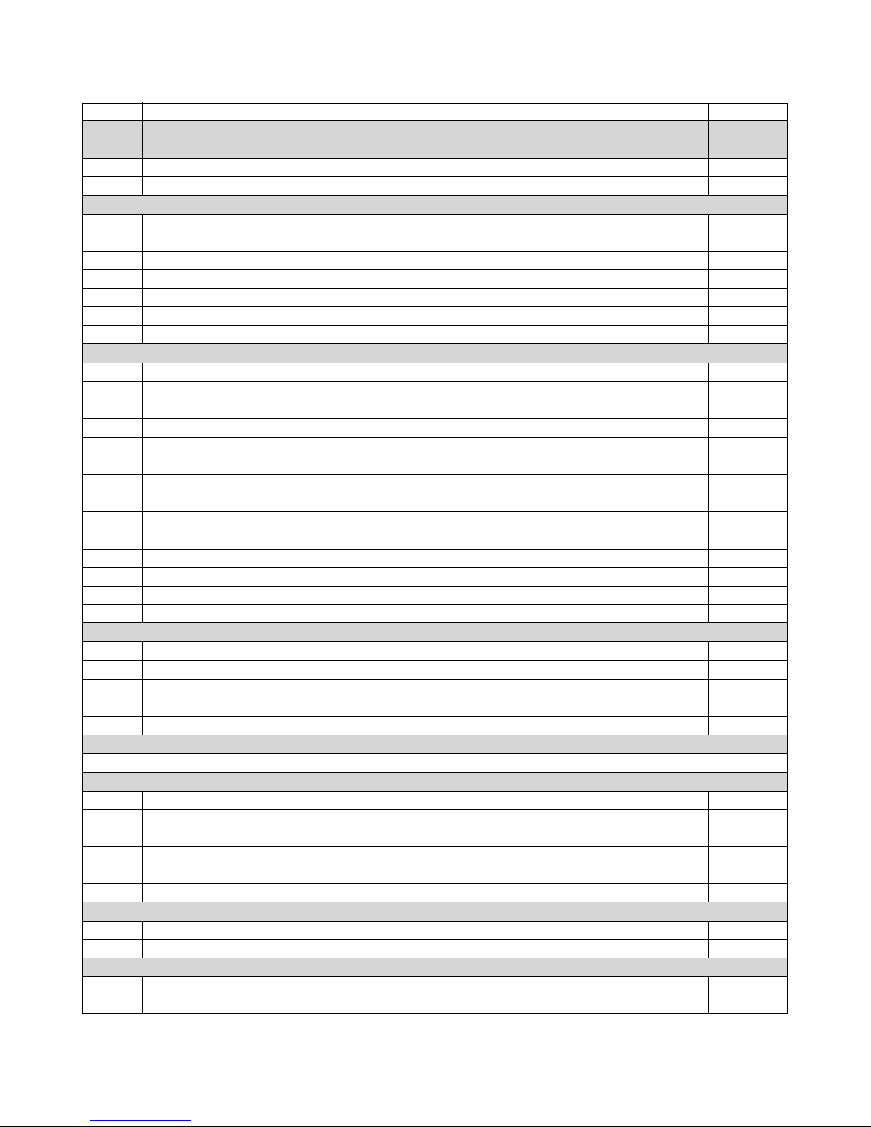
Fig 1.
8. ELECTRICAL CONNECTIONS
The unit operates from a 220/240v1-50hz or a 400v- 3-50hz electrical supply as denoted in the technical data.
For 60hz application consult Foster.
The selection of mains cable depends on the unit (Amps) and on the siting of the cable itself.
The installer will therefore evaluate the most suitable one on a case by case basis.
The table below gives a rough sizing and should be used as a guide only
Unit Amps Cable diameter
Up to 12 Amps 1.5mm
2
12 to 17 Amps 2.5mm
2
Over 17 Amps 4mm
2
Remove the front panel of the unit and connect the cables to the terminal box as per the diagrams in fig 1,2,3 and 4.
11
Single Phase Unit
L1 – Brown
N – Blue
PE – yellow / green
BR BL YG
L 1
L 1
N
N
PE
Mains Supply Cable
230V/ three phase unit without neutral.
L1 – Brown L2 – Black
L3 – Blue
PE – yellow / green
BR BLK BL YG
L 2
L 2
L 3
L 3
N
N
Mains Supply Cable
Fig 2.
PE
PE
400V/ three phase unit with neutral.
L1 – Brown L2 – Black
N – Blue L3 – Black
PE – yellow / green
BR BLK BLK BL YG
L 2
L 2
L 3
L 3
N
N
Mains Supply Cable
Fig 3.
PE
PE
L 1
L 1
L 1
L 1
Connections for options
1 = Brown 5 = Brown
2 = Blue 6 = Blue
3 = Brown
4 = Blue
= yellow/green
BR BL BR BL GV BR BL
Fig 4.
6
6
Door Heater
Remote Alarm Cable
5
5
1
1
2
2
3
3
4
4
Door Microswitch
PE
Page 14
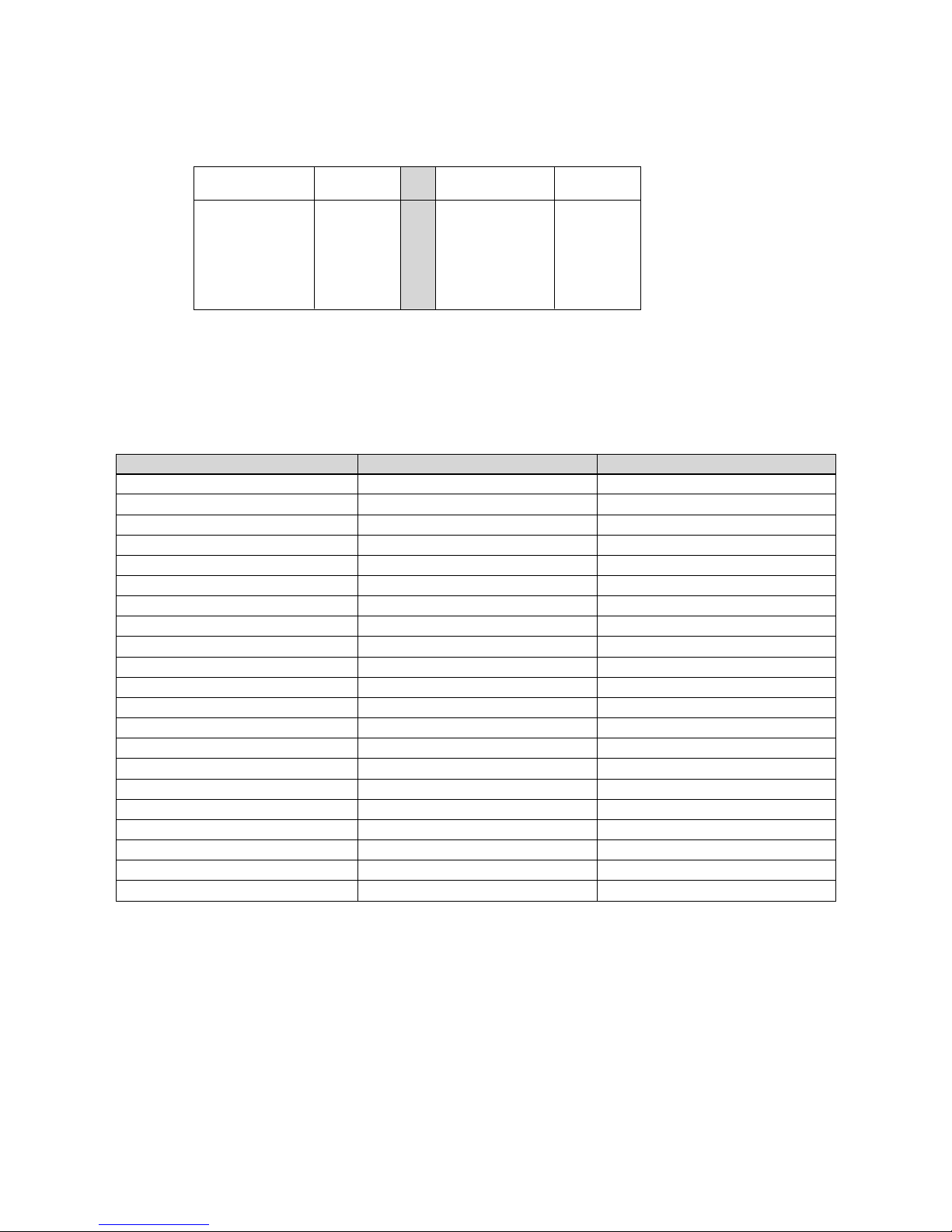
9. PROBE RESISTANCE VALUES
The air and defrost probes have the following temperature resistance values (K ohms)
Temperature Kohms Temperature Kohms
+50°C 4,161 0°C 27,280
+40°C 5,828 -10°C 42,450
+30°C 8,313 -20°C 67,740
+20°C 12,090 -30°C 111,300
+10°C 17,960 -40°C 188,400
10. FUSE RATINGS
NOTE: LA refers to Low Ambient Models
FOSTER CODE Internal fuse Wiring diagram
SP101HW 16 A J1018
SP201HW 16 A J1018
SP301HW 20 A J1018
SP401HW 25 A J1018
SP501HW No fuses J2020
SP601HW No fuses J2019
SP101LW 20 A J1018
SP201LW No fuses J2019
SP301LW No fuses J2019
SP101HW LA 16 A J1019
SP201HW LA 16 A J1019
SP301HW LA 20 A J1019
SP401HW LA 25 A J1019
SP501HW LA No fuses J2021
SP601HW LA No fuses J2022
SP101LW LA 20 A J1019
SP201LW LA No fuses J2022
SP301LW LA No fuses J2022
12
Page 15

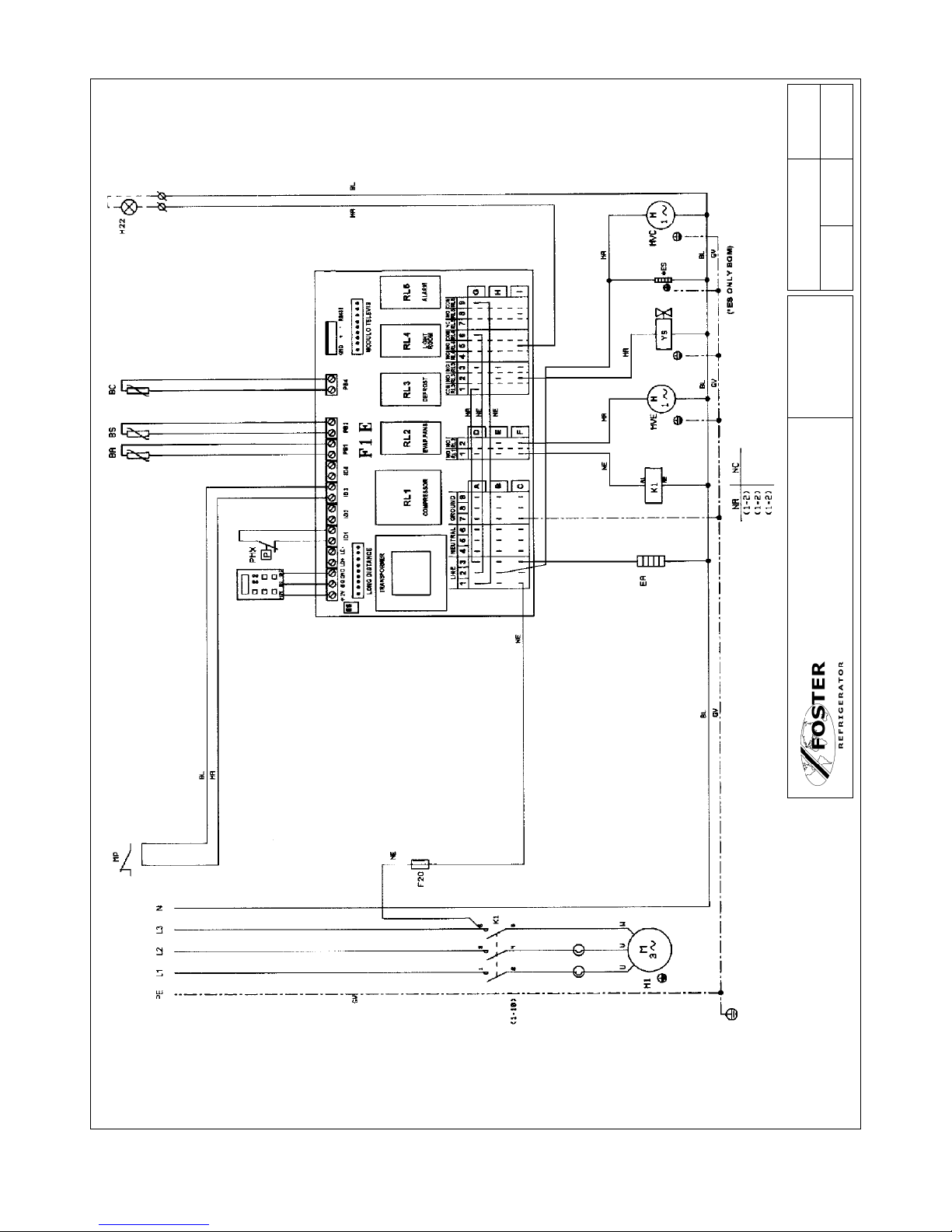
11. WIRING DIAGRAMS
ROOM SENSOR
CONDENSER ALARM SENSOR
DEFROST SENSOR
SPEED REGULATOR
SPEED REGULATOR SENSOR
DEFROST HEATER
RESISTENZA CARTER COMPRESSORE
COMPRESSOR CRANKCASE HEATER
DOOR HEATER CIRCUIT
CONTROL BOARD HEATER
VOLTAGE REGULATOR HEATER
CONDENSATE DRAIN HEATER
VOLTAGE REGULATOR FUSE
COMPRESSOR FUSE
ELECTRONIC CONTROL CAB
AUXILIARY FUSE
ROOM LIGHT FUSE
VOLTAGE REGULATOR
13
BA
BC
BS
BVR
BVRS
E
E1
M1
EP
ER1
ER2
ES
F13
F1
F1E
FL
F20
FM
EMERGENCY ‘STAT
ALARM
CONTACTOR
DEFROST CONTACTOR
COMPRESSOR MOTOR Nr.1
DOOR MICROSWITCH(ROOM)
CONDENSER FAN MOTOR
EVAPORATOR FAN MOTOR
COND. FAN STARTING PRESSURE SWITCH
L/P SWITCH
H/P SWITCH
MAIN SWITCH
COND. FAN SPEED REGULATOR
“OFF” SWITCH
TRANSFORMER
TERMINAL BOARD-CONNECTOR
REFRIGERANT SOLENOID
HOT GAS SOLENOID
FTE
HI
K1
K11
M1
MPC
MVC
MVE
P1MX
PMI
PMX
Q1
Q3
T
X
YS
YG
COMPONENT IDENTIFICATION
Page 16
14
SUPPLY
400V/3N-/50Hz
Colour Code
MA - BROWN
BL - BLUE
GV - GREEN/YELLOW
NE - BLACK
Drawing No. Sheet No.
J2020 1 of 1
Drawn By Approved Date
Title
SP501HW
FOSTER REFRIGERATOR - A Division of ITW
Ltd.
Page 17

15
LOW TEMP ONLY
SUPPLY
230-220V/1N-/50Hz
Colour Code
MA - BROWN
BL - BLUE
GV - GREEN/YELLOW
NE - BLACK
Drawing No. Sheet No.
J1018 1 of 1
Drawn By Approved Date
Title
SP101LW
SP101HW
SP201HW
SP301HW
FOSTER REFRIGERATOR - A Division of ITW
Ltd.
SP101LW
SPE
Page 18

16
SUPPLY
400V/3N-/50Hz
Colour Code
MA - BROWN
BL - BLUE
GV - GREEN/YELLOW
NE - BLACK
Drawing No. Sheet No.
J2019 1 of 1
Drawn By Approved Date
Title
SP201LW
SP301LW
SP601HW
FOSTER REFRIGERATOR - A Division of ITW
Ltd.
Page 19

PART 1B
Ceiling Mounted Solo January 2003 Controller Settings
Dimensions
Description
1. Condensing unit and Evaporator (evaporator plaed in an insulated box) located outside of the coldroom.
2. Air inlet and outlet to the evaporator located inside the coldroom.
3. Electrical control panel located in the condensing unit enclosure.
4. Wall mounted control panel.
A B C D E F G H I L M X Y
SP1/SP2 357 250 719 340 122 28 332 506 60 620 545 337 550
SP3/SP4 390 250 809 360 122 28 332 540 60 820 745 337 750
SP5 427 250 929 410 122 98 452 645 60 820 745 458 750
17
Page 20

WALL MOUNT SOLO PLUS TECHNICAL DATA
Foster Nom. HP Cut Out HP Cut In Suction Valve Noise Heat Rejected RoomVent 32°C Ambient 43°C Ambient Air Air Vol Electrical Nominal Defrost Condensate Net Gross
Model No. HP Press Bar Press Bar Press Bar Level dBa Max Watts @ 32°C
m
3
/ h # Watts Room Cap Watts Room Cap Throw mts m
3
/ h
Volts
Phase
Hz
Amps Watts Type Vaporisation Wt. Kg Wt. Kg
NOTE: Noise levels taken in a room with a concrete floor, no sound attenuation and ceiling height of 7 metres with the unit base 1.5 metres from floor level, installed in a coldroom and the Sound Metre 3 metres distance.
SP 1HC 0.625 28 23 ———- 59 2300 750 1550 10 1400 7 3 550 230 1 50 4.4 700 Hot Gas Auto 59 90
SP 2HC 0.75 28 23 ———- 60 2675 750 1750 12 1600 10 3 550 230 1 50 5.2 800 Hot Gas Auto 59 90
SP 3HC 1 28 23 ———- 60 3750 1400 2600 20 2200 16 3.5 1100 230 1 50 6.9 1100 Hot Gas Auto 74 114
SP 4HC 1.2 28 23 ———- 60 4200 1400 2900 28 2700 22 3.5 1100 400 3 50 4.4 1500 Hot Gas Auto 75 115
SP 5HC 2 28 23 ———- 63 7200 5200 5200 56 4600 48 6 2300 400 3 50 5.1 2100 Hot Gas Auto 93 139
STORAGE TEMP +10°C
Foster Ref Qty Capillary Size
Model No. Gas Grms No. x Dia x Len
SP 1HC R404A 0.54 1 x 1.63 x 2200
SP 2HC R404A 0.60 1 x 1.83 x 3100
SP 3HC R404A 0.73 2 x 1.38 x 3100
SP 4HC R404A 0.70 2 x 1.98 x 2900
SP 5HC R404A 1.10 2 x 1.98 x 2000
Foster Nom. HP Cut Out HP Cut In Suction Valve Noise Heat Rejected RoomVent 32°C Ambient 43°C Ambient Air Air Vol Electrical Nominal Defrost Condensate Net Gross
Model No. HP Press Bar Press Bar Press Bar Level dBa Max Watts @ 32°C
m
3
/ h # Watts Room Cap Watts Room Cap Throw mts m
3
/ h
Volts
Phase
Hz
Amps Watts Type Vaporisation Wt. Kg Wt. Kg
SP 1HC 0.625 28 23 ———- 59 1950 750 1150 7 1050 6 3 550 230 1 50 4.4 700 Hot Gas Auto 59 90
SP 2HC 0.75 28 23 ———- 60 2200 750 1350 9 1250 6 3 550 230 1 50 5.2 800 Hot Gas Auto 59 90
SP 3HC 1 28 23 ———- 60 2850 1400 1900 17 1600 10 3.5 1100 230 1 50 6.9 1100 Hot Gas Auto 74 114
SP 4HC 1.2 28 23 ———- 60 3350 1400 2300 20 2050 12 3.5 1100 400 3 50 4.4 1500 Hot Gas Auto 75 115
SP 5HC 2 28 23 ———- 63 5700 1500 4100 46 3600 28 6 2300 400 3 50 5.1 2100 Hot Gas Auto 93 139
Foster Nom. HP Cut Out HP Cut In Suction Valve Noise Heat Rejected RoomVent 32°C Ambient 43°C Ambient Air Air Vol Electrical Nominal Defrost Condensate Net Gross
Model No. HP Press Bar Press Bar Press Bar Level dBa Max Watts @ 32°C
m
3
/ h # Watts Room Cap Watts Room Cap Throw mts m
3
/ h
Volts
Phase
Hz
Amps Watts Type Vaporisation Wt. Kg Wt. Kg
SP 1HC 0.625 28 23 ———- 59 1750 750 1050 6 925 4 3 550 230 1 50 4.4 700 Hot Gas Auto 59 90
SP 2HC 0.75 28 23 ———- 60 2000 750 1200 7 1100 5 3 550 230 1 50 5.2 800 Hot Gas Auto 59 90
SP 3HC 1 28 23 ———- 60 2650 1400 1700 12 1450 9 3.5 1100 230 1 50 6.9 1100 Hot Gas Auto 74 114
SP 4HC 1.2 28 23 ———- 60 3150 1400 2000 15 1700 12 3.5 1100 400 3 50 4.4 1500 Hot Gas Auto 75 115
SP 5HC 2 28 23 ———- 63 5100 1500 3600 36 3200 17 6 2300 400 3 50 5.1 2100 Hot Gas Auto 93 139
Foster Nom. HP Cut Out HP Cut In Suction Valve Noise Heat Rejected RoomVent 32°C Ambient 43°C Ambient Air Air Vol Electrical Nominal Defrost Condensate Net Gross
Model No. HP Press Bar Press Bar Press Bar Level dBa Max Watts @ 32°C
m
3
/ h # Watts Room Cap Watts Room Cap Throw mts m
3
/ h
Volts
Phase
Hz
Amps Watts Type Vaporisation Wt. Kg Wt. Kg
SP 2LC 1.7 28 23 3 60 2050 750 1200 6 1050 3 3 550 230 1 50 5.9 900 Hot Gas Auto 68 99
SP 3LC 2 28 23 3 61 2850 1400 1650 11 1400 7 3.5 1100 400 3 50 4.2 1400 Hot Gas Auto 87 118
SP 4LC 3 28 23 3 63 5000 1400 2400 18 220 13.5 6 2300 400 3 50 4.6 1800 Hot Gas Auto 102 142
Foster Ref Qty Capillary Size
Model No. Gas Grms No. x Dia x Len
SP 1HC R404A 0.54 1 x 1.63 x 2200
SP 2HC R404A 0.60 1 x 1.83 x 3100
SP 3HC R404A 0.73 2 x 1.38 x 3100
SP 4HC R404A 0.70 2 x 1.98 x 2900
SP 5HC R404A 1.10 2 x 1.98 x 2000
Foster Ref Qty Capillary Size
Model No. Gas Grms No. x Dia x Len
SP 1HC R404A 0.54 1 x 1.63 x 2200
SP 2HC R404A 0.60 1 x 1.83 x 3100
SP 3HC R404A 0.73 2 x 1.38 x 3100
SP 4HC R404A 0.70 2 x 1.98 x 2900
SP 5HC R404A 1.10 2 x 1.98 x 2000
STORAGE TEMP +10°C STORAGE TEMP +1/4°C STORAGE TEMP 0/-2°C
STORAGE TEMP +1/4°C
STORAGE TEMP 0/-2°C
STORAGE TEMP -18/-21°C
Foster Ref Qty Capillary Size
Model No. Gas Grms No. x Dia x Len
SP 1LC R404A 0.42 1 x 1.49 x 1900
SP 2LC R404A 0.72 1 x 1.98 x 3000
SP 3LC R404A 0.96 2 x 1.63 x 2900
STORAGE TEMP -18/-21°C
18
Page 21

19
1) Control LED (GREEN)
ON: Compressor running, unit refrigerating.
FLASHING: Compressor is in Start Delay mode.
OFF: Compressor off, Room down to temperature
2. Control LED (GREEN)
ON: Evaporator fan running.
FLASHING: Evaporator fan in start delay mode.
OFF: Evaporator fan off. Unit in defrost mode.
3. Control LED (YELLOW)
ON: Unit in Automatic or Manual defrost.
4. Alarm LED (RED)
ON: Alarm activated due to Sensor failure, pressure switch intervention or coldroom temperature
outside set values.
OFF: Unit operating normally.
5. DISPLAY: On connection to the main supply OFF is displayed indicating the statues of the unit.
By pressing the ON/OFF key for 3 seconds the unit is turned on with the room temperature
displayed. In the programming mode the parameters are displayed and if an alarm occurs the
code is displayed.
6. SET key: When pressed for two seconds it illuminates and allows the room temperature to be
set. During programming it is used to pass from submenu to an upper menu.
7. DOWN/ROOM LIGHT key: In programming mode or when setting room temperature it is used
to reduce the displayed value.
At other times it is used to turn the coldroom light on or off.
8. MANUAL DEFROST/UP key: In programming mode or when settings room temperature it is
used to increase the displayed value.
Manual defrost initiated if pressed for more then 5 seconds.
Page 22

20
ROOM TEMPERATURE SETTINGS.
Set the required room temperature.
With the unit in normal operating mode press the SET key to display the set temperature.
To change the value press either the UP/DEFROST key or the DOWN/INTERIOR LIGHT key.
Once you have reached the desired setting press SET key to confirm and store the change.
INSTRUCTION FOR PARAMETER MODIFICATION
ACCESSING THE PARAMETERS
Press and hold the ENTER key for 5 seconds.
“00” will be displayed.
Press the UP/DEFROST key till it displays “22”
The first parameter to be changed will be displayed.
Press the UP/DEFROST key or the DOWN/INTERIOR LIGHT key to scroll through the
parameters.
Press the SET key to display the value of the parameter selected.
To change the value press either the UP/DEFROST key or the DOWN/INTERIOR LIGHT key
until you reach the new value.
9. ON/OFF key: When pressed for 2 seconds it turns the unit off or on.
10. ENTER key: Allows access to the menu and submenus.
Access to the programming mode should only be attempted after reading and fully
understanding the service manual, as inserting incorrect information will effect the operation of
the unit.
Page 23

Press the SET key to display the value of the parameter selected.
To change the value press either the UP/DEFROST key or the DOWN/INTERIOR LIGHT key
until you reach the new value.
Press the SET key to confirm the value.
Repeat the operation to modify the required parameters.
To memorise the new values and exit the parameters press the ENTER key.
NOTE: If you do not press the ENTER key the new values will not be memorised.
If no buttons are pressed for 60 seconds the controller will revert to normal operation.
21
Page 24

22
Page 25

PROBE RESISTANCE VALUES
The air and defrost probes have the following temperature resistance values (K ohms)
FOSTER CODE INTERNAL FUSE VOLTAGE WIRING DIAGRAM
SP1HC 16 A 230/1/50 81800LSB
SP2HC 20 A 230/1/50 81800LSB
SP3HC 20 A 230/1/50 81800LSB
SP4HC 10 A 400/3/50 81802LSB
SP5HC 16A 400/3/50 81802LSB
SP2LC 20A 230/1/50 81800LSB
SP3LC 16A 400/3/50 81802LSB
SP4LC 16A 400/3/50 81802LSB
CONTROLLER ALARMS AND FAULT FINDING
When an alarm condition occurs the unit will display an alarm code ERR (this will differ according to the nature of
the alarm):
High Temperature Alarm.
In the event of a high temperature alarm,
HI and the room temperature will be displayed alternately.
Possible cause:
To frequent door openings.
The product load in the room exceeds the room capacity.
The temperature of the product stored in the room is too high.
Refrigeration system malfunction.
Low Temperature Alarm.
In the event of a high temperature alarm,
LO and the room temperature will be displayed alternately.
Possible cause:
Faulty PCB.
Room Temperature Probe Alarm.
In the event of a room temperature probe alarm,
E0 will be displayed.
Room temperature probe not connected correctly.
Faulty probe.
Evaporator Probe Alarm.
In the event of a room temperature probe alarm,
E1 will be displayed.
Evaporator probe not connected correctly.
Faulty probe.
FUSE RATINGS
Temperature Kohms Temperature Kohms
+50°C 4,161 0°C 27,280
+40°C 5,828 -10° C42,450
+30°C 8,313 -20° C67,740
+20°C 12,090 -30° C111,300
+10°C 17,960 -40° C188,400
23
Page 26

High Pressure Alarm (HH)
Each time the pressure switch trips, the buzzer and red LED are activated. If more than ten trips occur during a
1-hour period then the unit will shut down automatically. The remote relay will be activated and the label ERR will
flash on the display alternating with the room temperature. The alarm code EO is displayed in the Alarm Menu.
The cause can be:
• Dirty condenser
• Condenser fan not running
• Front cover not fitted
• Obstructed condenser air inlet
• Obstructed condenser air outlet
• Inadequate ventilation
TROUBLE SHOOTING
1) Compressor stops. There is an internal over temperature device (Klixon) that stops the compressor each time the
admissible temperature of the motor windings is exceeded.
Possible causes are:
• Insufficient ventilation to the compressor
• Mains voltage anomaly
• Faulty condenser fan
The device will re-set automatically when the windings cool down.
2) Formation of ice on evaporator coil impeding airflow.
Possible causes are:
• Excessive door openings
• Door left open for long periods
• Evaporator fan/s faulty
• Door switch faulty (if fitted)
• Faulty defrost heater (if fitted)
• Faulty hot gas solenoid valve (if fitted)
• Pre set defrost routine not sufficient to clear evaporator of ice build up.
• Decrease the time interval between defrosts.
3) Display does not illuminate.
• Is their power to the unit?
• Is the mains cable connected correctly?
• Have the fuses in the electrical panel blown?
24
Page 27

Colour Code
MA - BROWN
BL - BLUE
GV - GREEN/YELLOW
NE - BLACK
Drawing No. Sheet No.
81802LSB 1 of 1
Drawn By Approved Date
Title
SP3LC
SP4LC
SP4HC
SP5HC
FOSTER REFRIGERATOR - A Division of ITW
Ltd.
25
Page 28

Colour Code
MA - BROWN
BL - BLUE
GV - GREEN/YELLOW
NE - BLACK
Drawing No. Sheet No.
81800LSB 1 of 1
Drawn By Approved Date
Title
SP1C
SP1HC
SPE
SP2HC
SP2LC
FOSTER REFRIGERATOR - A Division of ITW
Ltd.
SP3HC
SP3HC
SPE
26
Page 29

27
SOLO PLUS
Service Manual
Page 30

WALL MOUNTED UNITS AIR FLOW DIRECTION
Wall mounted
Ceiling mounted
CEILING MOUNTED UNITS
DIMENSIONS
MODEL CONDENSER UNIT EVAPORATOR UNIT PLUG SIZE CUT-OUT SIZE
A x B x C (mm) G x E x F (mm) W x H (mm) W X H (mm)
H x J x K (mm) I x M x N (mm)
SP 1 H & LW 454 x 735 x 305 420 x 420 x 300 420 x 300 425 x 305
SP 2 H & LW 454 x 735 x 305 420 x 420 x 300 420 x 300 425 x 305
SP 3 H & LW 754 x 735 x 305 720 x 420 x 300 720 x 300 725 x 305
SP 4 HW 754 x 735 x 305 720 x 420 x 300 720 x 300 725 x 305
SP 4 LW 754 x 840 x 400 720 x 580 x 470 720 x 470 725 x 475
SP 5 H & LW 754 x 840 x 400 720 x 580 x 470 720 x 470 725 x 475
SP 1 HC 620 x 719 x 357 545 x 150 x 332 545 x 332 550 x 337
SP 2 H & LC 620 x 719 x 357 545 x 150 x 332 545 x 332 550 x 337
SP 3 H & LC 820 x 809 x 390 745 x 150 x 332 745 x 332 750 x 337
SP 4 HC 820 x 809 x 390 745 x 150 x 332 745 x 332 750 x 337
SP 4 LC 820 x 929 x 427 745 x 220 x 452 745 x 452 750 x 458
SP 5 HC 820 x 929 x 427 745 x 220 x 452 745 x 452 750 x 458
NOTE: W = wall mounted unit. C = ceiling mounted unit
C
D
E
A
D=100mm
N
J
H
I
28
Page 31

SOLO PLUS REFRIGERATION SYSTEM
CONTENTS PAGE INTRODUCTION
Introduction 23 Solo Plus is a range of packaged refrigeration
s y stems compri s ing of 10 Wall Models an d 8
Technical Data 24 Ceiling Models.
The systems are pre-charged with refrigerant and
Access 25 pre-wired ready for installation into a coldroom with
only electrical connections to be made. No external
Controller Operation 25-26 drain is required.
Units will operate up to 43°C ambient conditions
Controller Parameters 27-33 (ISO Climate Class 5). If installed outside neither
the coldroom or the Solo is weatherproof, therefore
Controller Inputs / Outputs 34 suitable protection must be provided.
Probe Resistance Values 34
Electrical Connections 35
Fuses 36 Table 1. Storage Conditions °C
Unit Type Refrigerator Meat Freezer
Controller Fault Finding 37
Temp +10 +1/+4 0/-2 -18/21 -25
Model SP1HW SP1HW SP1HW SP1LW
Controller Emergency Repair 38 SP2HW SP2HW SP2HW SP2LW SP2LW
SP3HW SP3HW SP3HW SP3LW SP3LW
Routine Maintenance 38 SP4HW SP4HW SP4HW SP4LW SP4LW
SP5HW SP5HW SP5HW SP5LW SP5LW
Wiring Diagrams 39-44
SP1HC SP1HC SP1HC
SP2HC SP2HC SP2HC SP2LC SP2LC
SP3HC SP3HC SP3HC SP3LC SP3LC
SP4HC SP4HC SP4HC SP4LC SP4LC
SP5HC SP5HC SP5HC
NOTE!
Nomenclature “W” refers to Wall Model and “C” to
Ceiling model.
As each model operates at different temperatures it
w ill be ne c es sary to s e t r e quire d op e ratin g
Temperature. See Operating and Installation Manual.
29
Page 32

30
SOLO PLUS TECHNICAL DATA
Foster Refrigerant Qty Nom. HP Cut Out HP Cut In Suction Valve Noise Heat Rejected Room Vent. 32°C Amb. Room 43°C Amb. Room Air Air Vol Electrical Nominal Defrost Condensate Net Gross
Model No. Gms HP Press Bar Press Bar Press Bar Level dBa Max Watts @ 32°C m
3
/ h # Duty Watts Cap. m
3
Duty Watts Cap. m
3
Throw m m
3
/ h Volts Phase Hz Amps Watts Type Vaporisation Wt. Kg Wt. Kg
SP 1HW R 404a 650 0.625 60 2300 700 1450 12 1325 10 3 600 230 1 50 4.4 700 Hot Gas Auto 53 87
SP 2HW R 404a 650 0.75 60 2675 700 1750 15 1600 13 3 600 230 1 50 5.3 800 HG Auto 64 98
SP 3HW R 404a 900 1 60 3750 1400 2600 25 2200 20 4 1200 230 1 50 7.5 1200 HG Auto 77 116
SP 4HW R 404a 900 1.2 28 23 60 4200 1400 2900 32 2650 27 4 1200 400 3 50 5.1 1600 HG Auto 79 118
SP 5HW R 404a 1350 2 28 23 61 7200 1500 5200 64 4600 56 7 2300 400 3 50 4.5 1900 HG Auto 104 149
SP1HW R 404a 650 0.625 60 1950 700 1150 10 1050 8 3 600 230 1 50 4.4 700 HG Auto 53 87
SP 2HW R 404a 650 0.75 60 2200 700 1350 12 1250 9 3 600 230 1 50 5.3 800 HG Auto 64 98
SP 3HW R 404a 900 1 60 2850 1400 1900 21 1600 13 4 1200 230 1 50 7.5 1200 HG Auto 77 116
SP 4HW R 404a 900 1.2 28 23 60 3350 1400 2300 25 2050 16 4 1200 400 3 50 5.1 1600 HG Auto 79 118
SP 5HW R 404a 1350 2 28 23 61 5700 1500 4100 52 3600 28 7 2300 400 3 50 4.5 1900 HG Auto 104 149
SP 1HW R 404a 650 0.625 60 1750 700 1050 8 925 6 3 600 230 1 50 4.4 700 HG Auto 53 87
SP 2HW R 404a 650 0.75 60 2000 700 1200 9 1100 7 3 600 230 1 50 5.3 800 HG Auto 64 98
SP 3HW R 404a 900 1 60 2650 1400 1700 15 1450 11 4 1200 230 1 50 7.5 1200 HG Auto 77 116
SP 4HW R 404a 900 1.2 28 23 60 3150 1400 2000 18 1700 14 4 1200 400 3 50 5.1 1600 HG Auto 79
118
SP 5HW R-404a 1350 2 28 23 61 5100 1500 3600 38 3200 28 7 2300 400 3 50 4.5 1900 HG Auto 104 149
SP 1LW R 404a 580 1.5 3 61 1600 700 925 5 800 4 3 530 230 1 50 4.1 700 HG Auto 61 95
SP 2LW R 404a 530 1.7 3 61 2050 700 1200 8 1050 6 3 600 230 1 50 5.5 900 HG Auto 64 98
SP 3LW R 404a 800 2 28 23 3 61 2850 1400 1650 12 1450 9 4 1060 400 3 50 6.1 1000 HG Auto 88 127
SP 4LW R 404a 1300 2 28 23 3 62 4100 1400 2100 20 1600 13 7 2300 400 3 50 4.8 2100 HG Auto 106 151
SP 5LW R 404a 1300 3 28 23 3 62 5000 1500 2400 25 2200 20 7 2300 400 3 50 4 1700 HG Auto 112 157
SP 2LW R 404a 530 1.7 3 61 1650 700 950 4 825 3 3 600 230 1 50 5.5 900 HG Auto 64 98
SP 3LW R 404a 800 2 28 23 3 61 3300 1400 1200 8 1000 5 4 1060 400 3 50 6.1 1000 HG Auto 88 127
SP 4LW R 404a 1300 2 28 23 3 61 1400 1550 11 1300 7 7 2300 400 3 50 4.8 2100 HG Auto 106 151
SP 5LW R 404a 1300 3 28 23 3 62 3600 1500 2000 17 1650 11 7 2300 400 3 50 4 1700 HG Auto 112 157
SP 1HC R 404a 570 0.625 59 2300 750 1550 10 1400 7 3 550 230 1 50 4.4 700 HG Auto 59 90
SP 2HC R 404a 500 0.75 60 2675 750 1750 12 1600 10 3 550 230 1 50 5.2 800 HG Auto 59 90
SP 3HC R 404a 620 1 60 3750 1400 2600 20 2200 16 3.5 1100 230 1 50 6.9 1100 HG Auto 74 114
SP 4HC R 404a 600 1.2 28 23 60 4200 1400 2900 28 2700 22 3.5 1100 400 3 50 4.4 1500 HG Auto 75 115
SP 5HC R 404a 1040 2 28 23 63 7200 1500 5200 56 4600 48 6 2300 400 3 50 5.1 2100 HG Auto 93 139
SP 1HC R 404a 570 0.625 59 1950 750 1150 7 1050 5 3 550 230 1 50 4.4 700 HG Auto 59 90
SP 2HC R 404a 500 0.75 60 2200 750 1350 9 1250 6 3 550 230 1 50 5.2 800 HG Auto 59 90
SP 3HC R 404a 620 1 60 2850 1400 1900 17 1600 10 3.5 1100 230 1 50 6.9 1100 HG Auto 74 114
SP 4HC R 404a 600 1.2 28 23 60 3350 1400 2300 20 2050 12 3.5 1100 400 3 50 4.4 1500 HG Auto 75 115
SP 5HC R 404a 1040 2 28 23 63 5700 1500 4100 46 3600 28 6 2300 400 3 50 5.1 2100 HG Auto 93 139
SP 1HC R 404a 570 0.625 59 1750 750 1050 6 925 4 3 550 230 1 50 4.4 700 HG Auto 59 90
SP 2HC R 404a 500 0.75 60 2000 750 1200 7 1100 5 3 550 230 1 50 5.2 800 HG Auto 59 90
SP 3HC R 404a 620 1 60 2650 1400 1700 12 1450 9 3.5 1100 230 1 50 6.9 1100 HG Auto 74 114
SP 4HC R 404a 600 1.2 28 23 60 3150 1400 2000 15 1700 12 3.5 1100 400 3 50 4.4 1500 HG Auto 75 115
SP 5HC R 404a 1040 2 28 23 63 5100 1500 3600 36 3200 26 6 2300 400 3 50 5.1 2100 HG Auto 93 139
SP 2LC R 404a 420 1.7 3 60 2050 750 1200 6 1050 3 3 550 230 1 50 5.9 900 HG Auto 68 99
SP 3LC R 404a 800 2 28 23 3 61 2850 1400 1650 11 1400 7 3.5 1100 400 3 50 4.2 1400 HG Auto 87 118
SP 4LC R 404a 1000 3 28 23 3 63 5000 1400 2400 18 2200 13.5 6 2300 400 3 50 4.6 1800 HG Auto 102 142
SP 2LC R 404a 420 1.7 3 60 1650 750 950 3 825 2 3 550 230 1 50 5.9 900 HG Auto 68 99
SP 3LC R 404a 800 2 28 23 3 61 3300 1400 1200 6 1000 4 3.5 1100 400 3 50 4.2 1400 HG Auto 87 118
SP 4LC R 404a 1000 3 28 23 3 63 3600 1400 2000 10 1650 6 6 2300 400 3 50 4.6 1800 HG Auto 102 142
NOTE: Noise levels taken in a room with a concrete floor, no sound attenuation and ceiling height of 7 metres with the unit base 1.5 metres from floor level, installed in a coldroom and the Sound Meter 3 metres distance.
# Room Ventilation requirements if the Solo is installed in a confined area. Solo 10.wk4.mgr 23.2.98. Revised 1-8-1998.
STORAGE TEMP -25°C
STORAGE TEMP -18/-21°C
STORAGE TEMP +1/+ 4°C
STORAGE TEMP 0/-2°C
STORAGE TEMP +10°C
STORAGE TEMP -18/-21°C
STORAGE TEMP -25 °C
STORAGE TEMP 0/-2°C
STORAGE TEMP +1/+4°C
STORAGE TEMP +10°C
Page 33

31
ACCESS TO THE UNIT COMPARTMENT / EVAPORATOR HOUSING
WALL MODEL
Front Panel: Remove the 2 fixing screws located under the base of the front panel and “pull forward”
releasing
it from the 4 “spring clips” located in each corner.
Condenser Fan After removing the front panel “pull upwards” the fan housing assembly releasing it from the 4
Assembly: “spring clips” located in each corner.
Evaporator Remove the 4 fixing screws from holding the drain pan in position and the side panel fixing
screws.
Assembly: Take the panel allowing access into the evaporator fan assembly.
CEILING MODEL
Unit Housing: Remove the 4 fixing screws from the front panel and “pull upwards” to release it from the 2
spring
clips located at the top.
Evaporator Remove the 4 fixing screws from the fan plate and lower allowing access to the evaporator fan
Assembly: motor and the evaporator assembly.
CONTROLLER OPERATION
DESCRIPTION OF ELECTRONIC PANEL
1) COMPRESSOR LED (Green)
LIT: the compressor is running. The unit is cooling.
FLASHING: the compressor is in a delayed start mode
OFF: the compressor is OFF. The required room temperature has been reached.
2) EVAPORATOR FAN LED (Green)
LIT:
evaporator fan is running.
FLASHING: the evaporator fan is in a delayed start mode
OFF: the evaporator fan is OFF. Unit in defrost mode.
3) DEFROST LED (Yellow)
LIT:
automatic or manual defrost in progress.
4) ALARM LED (Red)
LIT: alarm mode: malfunctioning of a sensor, or intervention of pressure-stat or
room temperature outside preset limits.
OFF: unit working normally.
4 5 9 10
3
2
1
6 7 8 11
Page 34

32
ROOM TEMPERATURE SETTING
With the unit in normal operating mode, the only active keys are “ON/OFF” (10) and “LAMP” (11). The latter is always
operative except when in programming mode.
Room temperature programming:
- Press key (10) to turn ON unit. The actual room temperature will be shown on the display (5). In this condition the
unit is ready for programming. It is necessary therefore to set the required room temperature bearing in mind the
limits of the range which the unit is able to operate.
- Press the SET key (6) (the yellow LED will light). The last set temperature will be displayed on the display screen
(5)
which shows the set value.
- Press the SET key (6), the yellowLED will light for one second and the display (5) will start flashing a few seconds
later, indicating the set temperature. If you wish to change the setting, use the following keys:
(8) to raise set temperature
(7) to lower set temperature
Once the required setting is displayed, press the SET key (6) to confirm.
The unit is now fully operational and no other programming is required. The refrigerating cycle is fully automatic according
to factory-set parameters, that can eventually be modified by authorised personnel only.
Minimum Temp Maximum Temp Recommended Temp
“H” Range - 5 °C + 10 °C
General Purpose + 3°C
Chilled + 1°C
Fresh Meat - 2°C
“L” Range -25 °C - 15 °C - 21°C
5) DISPLAY
When the machine is not in operation, the label “OFF” and the cell temperature are intermittently displayed
one after the other on the digital display. When the machine is in operation, during the normal working cycle,
the display indicates the room temperature. Parameters being set will be displayed during programming.
A “Fault Code” will be displayed during an alarm mode.
6) “SET” KEY -
Permits entry of room temperature requirements.
7) “DOWN” KEY - Key to decrease data values.
8) “MAN.DEF./UP” KEY - Key to increase data values
Press for 8 seconds at least to initiate manual defrost as well.
9) KEY “T.A.A.” - Key to mute audible alarm
This alarm is not fitted as standard to the unit but can be added by the client. To connect use the free terminals
1 & 2 (volt free) on the internal electronic panel. Terminal 2 should have a live feed brought to it.
10) “ON/OFF” KEY - Main switch
11) “LAMP” KEY - Push to turn room lamp ON/OFF. A red LED lights when lamp is ON.
Page 35

33
INSTRUCTIONS FOR PARAMETER MODIFICATION
1. HOW TO SET THE PARAMETERS:
1A. Keep the keys and pressed together for more than 5 seconds.
1B. “00” will be displayed.
1C. Press the key to display 22 (password)
1D. Confirm with
1E. The first parameter to be changed will be displayed.
To modify parameters see next section “Parameters modification”.
2. PARAMETER MODIFICATION:
To modify a parameter please follow the instruction given here under:
2A. Press or to display the parameter of which you want modify the value (see user
parameters).
2B. Press the key to display the value connected to the parameter.
2C. Modify the value pressing and until you reach the required one.
2D. Press the key to confirm temporarily the new value and return to the display of the parameter code.
2E. Repeat every operation code from point 2A in order to modify the other parameters’ values.
3. MEMORISATION OF NEW VALUES:
To modify a parameter please follow the instruction given here under:
3A. Press the key to memorise all the new values and exit the parameter modification proceedure.
TO EXIT WITHOUT MODIFYING PARAMETERS: do not press any key for at least 60 seconds. (exit for TIME OUT).
ATTENTION:
If you do not press the key after the parameter changes, all modifications selected will be lost.
Page 36

PARAMETERS DESCRIPTION
TEMPERATURE PROBE SETTING
C: CALIBRATION
It allows to add an offset to the measured value. It is active only with the air probe, while the evaporator probe
cannot be calibrated.
2: DIGITAL FILTER
It allows to define the coefficient used in the digital filter of the measured value. High values for this parameter
allow to reduce the noise present in the input lines (but the measure operation is slower). The suggested value
is 4.
3: INPUT LIMITATION
It allows to define the maximum range of the measure in a machine cycle. Low values of the parameter allow to
threshold the maximum variation of the measure, removing impulsive noise or spikes. The suggested value is
8.
4: VIRTUAL PROBE
The value used for regulation is an average of the value measured by the temperature probe and of the value
measured by the defrost probe.
5: CELSIUS / FAHRENHEIT
It allows to choose the operating temperature scale.
6: DECIMAL POINT
It allows to enable the decimal point in the range -9.9 to 19.9. (0=No, 1=YES).
rd: REGULATION DELTA
It defines the temperature differential used in the temperature set-point.
r1: MINIMUM SET ALLOWED
Defines the lower value when tuning the set-point of the device.
r2: MAXIMUM SET ALLOWED
Defines the upper value when tuning the set-point of the device.
r3: DIRECT/REVERSE
Enables or disables the Ed alarm display (defrost stopped for time-out). The alarm is handled anyway to allow
the supervisor to defect it.
r4: CURTAIN SET-POINT DELTA
It defines the variation of the set-point when operating with the curtain closed.
r5: MAXIMUM AND MINIMUM ENABLE
It enables or disables the display of the air probe maximum value rH and of the minimum value rL measured in
the tr time.
rt: MONITORING INTERVAL
It defines, in hours, the temperature monitoring time interval during which the parameters rH and rL are updated.
During the rt parameter display, pressing the down key it is possible to force a timer reset, setting automatically
rH = rL = Temperature.
rH e rL parameters reset occurs also when rt timer reaches its maximum value.
rH: MAXIMUM TEMPERATURE MEASURED DURING RT
Shows the maximum temperature measured by the air probe during the time interval rt.
34
Page 37

rL: MINIMUM TEMPERATURE MEASURED DURING rt.
Shows the minimum temperature measured by the air probe during the time interval rt.
C0: DELAY AFTER RESET
It delays the compressor and fan activation after the power on of the device, so to dispose the power consumption.
It also protects the compressor against repeated activations in case of power loss.
During the delay after reset the compressor LED blinks if the compressor should be activated. During this interval
the fan LED also blinks.
c1: MINIMUM TIME BETWEEN TWO COMPRESSORS POWER-ONs
It defines the minimum time pass between two compressor activations (it also defines the number of activations
per hour).
The start delay after reset is defined by the previous parameter.
c2: OFF MINIMUM TIME
It defines the time during which the compressor must be OFF after its deactivation.
c3: ON MINIMUM TIME
It defines the minimum time the compressor must be ON after its activation.
c4: SECURITY RELAY
If the air probe fault alarm becomes active, the ON time of the compressor is put to zero and the compressor
stays active for the time c4. The OFF time of the compressor is fixed to 15 minutes (the compressor LED blinks).
Fan act following the related parameters.
If the machine is in a defrost or in continuous cycle when an alarm for the air probe arises, the devise irreversibly
exits the procedures.
If the probe alarm stops, the device comes back to the standard operation mode ( not the operation mode it was
in before the alarm). If the compressor is OFF, a minimum OFF time is inserted; if it is ON, a minimum On time
is inserted.
If c4 = 0 the compressor is always OFF, if c4 = 100 the compressor is always ON.
DEFROST SETTINGS
d0: DEFROST TYPE
It defines the defrost type (0=electric, 1=hot gas, 2=electric with time-out, 3=hot gas with time-out)
If a time-based defrost is selected, the value measured by the defrost probe is ignored during defrost. Ed
alarm is never activated.
If the defrost probe results faulty, the E1 error is not displayed (it is then possible not to connect the probe).
d1: DEFROST INTERVAL
Defrost is executed when this parameter time-outs. If the time is 0, defrost is never executed
(exception is a manual defrost or a defrost driven by digital input).
During defrost, the temperature alarms are disabled.
dt: DEFROST-END SET-POINT
In the devices where the defrost-end temperature probe is installed, this parameter defines the defrost-
end evaporator temperature. This operation mode is active if the time-based defrost is not selected.
If the evaporator temperature is greater than the defrost-end set point when a defrost should be
started, the defrost is not initiated.
In any case the defrost is stopped when the dP time finishes. This event is shown displaying the Ed
message (defrost stopped for time-out), if Ed message is not disabled.
dP: DEFROST TIME
It defines the maximum duration of defrost.
In the devices where the defrost-end probe is present, or in the case where the time-based defrost
is not selected, this parameter represents the defrost time.
d4: AFTER-RESET DEFROST
35
Page 38

It allows to activate a defrost cycle when the device is turned on.
The selection of the after-reset defrost option has priority over the compressor regulation and over the continuous
cycle activation.
d5: DEFROST DELAY AFTER RESET OR EXTERNAL TRIGGER
It defines the time interval between the reset and the beginning of a defrost.
In case a digital trigger is used to start defrost, it defines the delay between the activation of defrost and its effective
start.
d6: DISPLAY LOCK DURING DEFROST
It allows to lock the display to the last value measured before defrost start.
The display comes back to normal operation when the temperature reaches for the first time its set-point or when
the d8 alarm exclusion time finishes.
If the display is not locked, during defrost the device displays the message dF.
dd: DRIPPING TIME
Compressor and fan are OFF for this time after a defrost cycle finishes.
If dd is not zero, the defrost stops when the device has turned the compressor OFF (in case of a hot gas defrost)
and the reverse cycle relay is turned OFF. If dd=0 the dripping phase is not initiated: after defrost only the reverse
cycle relay is deactivated.
d8: ALARMS EXCLUSION TIME AFTER DEFROST AND DOOR OPEN
After defrost the temperature alarm is inhibited for the time defined by this parameter. This allows the temperature
to exit the alarm range during and after defrost.
It also defines the time to inhibit the temperature alarm after door is closed if the door switch is active.
d9: FORCE DEFROST START
It allows to ignore the protection times for the compressor (minimum ON, minimum OFF, interval between two
ONs) when the defrost is started.
d : DEFROST PROBE MEASURE
It enables the display of the value measured by the defrost probe when this is connected.
dC: TIME BASE
It allows to modify the time base used for the defrost interval (dI) and the defrost duration (dP).
0=dI in hours, dP in minutes
1=dI in minutes, dP in seconds.
ALARMS
A0: ALARM AND FAN DELTA
It represents the temperature hystheresys of the “regulator” of alarm and of the fan regulator.
AL: MINIMUM RELATIVE SET
The low temperature alarm is activated when the temperature has values less than the minimum set relatively to
the set point.
If the parameter is 0 the minimum alarm is inhibited.
AH: MAXIMUM RELATIVE SET
The high temperature alarm is activated when the temperature has values greater than the maximum set relatively
to the set point.
If the parameter is 0 the maximum alarm is inhibited.
Ad: TEMPERATURE ALARM DELAY
The alarm of high and low temperatures is acknowledged with an Ad delay from the moment the cause starts.
This delay is active also at the reset of the device.
After defrost, door open/closed, continuous cycle, the temperature alarm is immediately acknowledged after the
delay set by the defrost and the continuous cycle.
36
Page 39

A4: DIGITAL INPUT 1
It defines the function of the digital input 1
A5: NUMBER 2 DIGITAL INPUT CONFIGURATION
Establishes the meaning of the number 2 digital input, where present.
A6: COMPRESSOR FAILURE DUE TO AN EXTERNAL ALARM
If an external alarm is active, the compressor remains active for a period of time equal to A6. The compressor’s
off-time is a fixed 15 minute period (the compressor’s arrow flashes intermittently).
Fans are programmed according to the relative parameters.
When A6=0, the compressor is always OFF, when A6=100 the compressor is always ON.
A7: DELAY TIME FOR ENTRY IN A4 OR A5
This establishes the delay between the activation of the alarm signal in a digital input and the activation of the
measures envisaged in case an alarm with delaying device is selected.
The first time the alarm occurs, delay A7 is activated. At the end of the timed period, if the alarm is still active,
this is indicated. Otherwise, the machine starts again from where it left off.
FANS
F0: FAN MANAGEMENT
0=fans always ON except for parameters F2, F3, Fd.
1=fans controlled by a specific fan regulator and by parameter Fd (post dripping stop).
2=fans controlled by the overall fan regulator (and by a parameter Fd).
The fans are always OFF during the dripping phase.
F1: FAN SWITCH OFF TEMPERATURE
Select the appropriate fan regulator F0=1
The fans will switch off when the temperature detected by the defrosting sensor exceeds the preset temperature
minus the value F1.
If the device detects an error in at least one of the two probes the fans regulator is disabled and the machine
behaves as if F0=0.
If the absolute fans regulator is selected, then F0=2.
Fans are turned on only when the evaporator temperature is less than Set Point + F1.
A0 is the differential used in this fans regulation.
If the device detects an error in the defrost probe, fans behave as if F0=0.
F2: OFF WHEN COMPRESSOR STOPPED
It is possible to force fans OFF when the compressor is stopped.
F3: FANS DURING DEFROST
The parameter is independent from the others; it defines the status of fans during defrost.
F3=1 OFF in defrost.
F3=0 ON in defrost.
Fd: STOP AFTER DRIPPING
After the dripping time it is possible to stop fans for some time.
37
Page 40

OTHER SETTINGS
H0: SERIAL ADDRESS
It defines the device network address for serial link.
H1: LIGHT/ALARM RELAY
It allows to define the function of the fourth relay : LIGHT, normally off ALARM or normally on ALARM.
P0: PRESSURESTAT
It is the maximum number of pressure alarms; when reached the machine gets the blocked status. If the number of
alarms is less than the one defined by this parameter, an autoresettable block situation is generated anyway.
P1: PRESSURESTAT TIMER
When the first pressure alarm is detected, a timer is loaded with the value (in seconds) defined by this parameter.
At the timeout, the alarm counter is automatically reset.
EA, EB, EE: ERROR IN DATA COLLECTION, CONTROL RESET
To restore correct operation, reset the default parameters:
• disconnect the machine from the mains supply;
• hold down key and connect to mains;
• the message “-C-” will appear on the digital display;
• in a few seconds, the equipment is in RESET mode and allows parameters to be modified (*);
• should the EE error persist, press until the error message disappears.
(*) The resetting of the default values cancels any alterations made to the parameters.
FLASHING ED: DEFROSTING TIMED OUT
• Check parameters dt, dP and d4;
• check the efficiency of the defrosting programme;
• if necessary, exclude the Ed alarm by using parameter r3.
FLASHING DF: DEFROSTING IN OPERATION
This is not an alarm signal, but an indication that the machine is defrosting. It appears when parameter d6=0.
38
Page 41

39
USER PARAMETERS
LABEL
C °C/F° -20 20 0 0
2 - 1 15 4 4
3 - 1 15 8 8
4 - 0 100 0 0
5 flag 0 1 0 0
6 flag 0 1 0 0
rd °C/F° 0,1 19,9 2 2
r1 °C/F° -40 r2 -5 -25
r2 °C/F° r1 199 10 -15
r3 flag 0 1 0 0
r4 °C/F° 0 20 0 0
r5 flag 0 1 0 0
rt ore 0 199 - rH °C/F° -50 90 - rL °C/F° -50 90 - c0 min 0 15 0 0
c1 min 0 15 3 3
c2 min 0 15 2 2
c3 min 0 15 0 0
c4 min 0 100 8 8
d0 flag 0 1 1 1
d1 ore 0 199 4 4
dt °C/F° -40 199 15 15
dP min 1 199 20 20
d4 flag 0 1 0 0
d5 min 0 199 0 0
d6 flag 0 1 0 0
dd min 0 15 2 2
d8 ore 0 15 1 1
d9 flag 0 1 0 0
d °C/F° - - - -
dC flag 0 1 0 0
A0 °C/F° 0,1 20 2 2
AL °C/F° 0 199 5 5
AH °C/F° 0 199 5 5
Ad min 0 199 199 199
A4 - 0 7 5 5
A5 - 0 7 0 0
A6 min 0 100 0 0
A7 min 0 199 0 0
F0 flag 0 1 0 0
F1 °C/F° 0 20 20 20
F2 flag 0 1 0 0
F3 flag 0 1 1 1
Fd min 0 15 1 1
H0 - 0 15 0 0
H1 flag 0 1 0 0
P0 flag 0 15 10 10
P1 min 0 199 60 60
CODE
T1 T2
UNIT OF
MEASURE
MANUFACTURER STANDARDS
OPERATING RANGE
Min Max
HOT GAS DEFROST
Range
H L
Page 42

40
INPUTS
Air Temperature Probe - Senses coldroom internal temperature. Negative temperature/resistance coefficient thermistor
probe.
Evaporator Temperature Probe - Senses temperature at the suction line outlet from the evaporator, required to terminate
defrosting. Negative temperature/resistance coefficient thermistor probe.
OUTPUTS
Compressor - Relay output switching single phase mains supply to the compressor direct or via a contactor for three
phase models.
Evaporator Fans - Relay output switching single phase mains supply to the evaporator fans.
Condenser Fans - Relay output switching single phase mains supply to the condenser fans.
Defrost - Relay output switching single phase mains supply to the hot gas solenoid valve.
Internal Light - Relay output switching single phase mains supply to the internal light (if fitted).
Door Frame Heater - Direct single phase mains supply to the door frame heater (if fitted).
External Alarm - Relay output switching single phase mains supply to an external alarm (if fitted).
CONTROLLER BOARD ELECTRICAL CONNECTIONS
Terminal Numbers Output
+/- Connection to keypad
2 External alarm (if fitted)
3 Mains in (3 phase models only)
19 / 20 Door switch (if fitted)
17 / 18 High pressure switch (SP 4H, 5H, 3L, 4L, 5L only)
13 / 14 Air probe
11 / 12 Defrost probe
45 Hot gas defrost valve
55 Condenser fan
21 Compressor or contractor coil (3 phase only)
22 Mains in (single phase)
44 Internal light (if fitted)
40 Door frame heater (if fitted)
50 Evaporator fan motor
70 Neutrals
60 Earth
RESISTANCE VALUES
The air and defrost probes have the following temperature resistance values (K ohms).
+50°C 4161 +10°C 17,960 –20°C 67,740
+30°C 8015 0°C 27,280 –30°C 111,300
+20°C 12,090 –10°C 42,450 –50°C 329,200
Page 43

41
ELECTRICAL CONNECTIONS
1. Check that the mains supply to the SOLO corresponds to the rating stamped on the serial no.plate.Tolerance: +/- 10%
of the nominal value.
2. Connection should always be made from a fused isolator or a switch-disconnector with fuses. We advise also the
use of a circuit breaker fitted in the line.
3. If a door operated microswitch is fitted to the coldroom connect the door switch to the door switch cable which exits
at
the top of the condensing unit. When the door is opened the coldroom light (if fitted, see below) will switch on and
the
evaporator fans the compressor will stop.
If a door microswitch is not fitted leave the door switch wire connected together and secure the cable inside the
condensing unit housing.
Note: Microswitch operation is closed when the door is closed. No microswitch is supplied with the unit.
4. The light output may be switched on/off using the key light on the controller facia. If the controller is to be used to switch
on/off the coldroom light, the supply should be taken from the light cable which exits from the top of the evaporator
housing. If an independent light switch is used the light cable from the evaporator housing should not be used. This
cable must be insulated and secured inside the evaporator housing.
5. Range “L” units (Low Temperature) are also fitted with a cable for door heater connection. It exits from the top of
the
condensing unit. If the door frame heater is rated at 24V, a transformer must be connected to step down the supply
voltage.
It is recommended that an appropriate fuse according to the door heater is used. If the door frame heater cable is
not used it must be insulated and secured inside the condensing unit housing.
6. Proceed with connection noting the colours of the wires in the mains supply cable provided as follows:
A) Single-phase supply 230V/1~/50 Hz 3 wires Blue = Neutral
Green/Yellow = Earth
Brown = Phase
B) Three-phase supply 230V/3~/50 Hz 4 wires Blue = Phase
Green/Yellow = Earth
Brown = Phase
Black = Phase
A) Single-phase supply 400V/3~/50 Hz 5 wires Blue = Neutral
Green/Yellow = Earth
Brown = Phase
Black = Phase
Black = Phase
N.B: Do not connect light switch cable, door heater or room indicator lamp to 230 V mains supply line.
Plates on each cable show the relevant connection to be made.
Page 44

42
POWER CURRENT FUSE: This is a fuse fitted in the line.
INTERNAL FUSES: We mean those fuses fitted in the control panel. Above list shows quantity, types and power.
N.B: All units are provided with a room light holder and a 60W. bulb. When replacing, use bulbs having a power not higher than 100
Watt.
SOLO
POWER
CURRENT FUSE
Type DIAZED
INTERNAL FUSES
MOD. Voltage n° Amp n° Dim Amp n° Dim Amp n° Dim Amp
SP1 HC 230V/1~/50 1 16 1 9x36 16
SP2 HC 230V/1~/50 1 20 1 9x36 16
SP3 HC 230V/1~/50 1 20 1 5x20 F 6
SP4 HC 400V/3~/50 3 10 1 5x20 F 6
SP5 HC 400V/3~/50 3 16 1 5x20 F 6
SP2 LC 230V/1~/50 1 20 1 5x20 F 6
SP3 LC 400V/3~/50 3 16 1 5x20 F 6
SP4 LC 400V/3~/50 3 16 1 5x20 F 6
CARD FUSE
Power fuse Auxiliary fuse
LIST OF FUSES
POWER CURRENT FUSE: This is a fuse fitted in the line.
INTERNAL FUSES: We mean those fuses fitted in the control panel. Above list shows quantity, types and power.
N.B: All units are provided with a room light holder and a 60W. bulb. When replacing, use bulbs having a power not higher than
100
Watt.
SOLO
POWER
CURRENT FUSE
Type DIAZED
INTERNAL FUSES
MOD. Voltage n° Amp n° Dim Amp n° Dim Amp n° Dim Amp
SP1 HW 230V/1~/50 1 16 1 9x36 16 1 5x20 F 6
SP2 HW 230V/1~/50 1 20 1 9x36 16 1 5x20 F 6
SP3 HW 230V/1~/50 1 25 1 5x20 F 6
SP4 HW 400V/3~/50 3 16 1 5x20 F 6
SP5 HW 400V/3~/50 3 20 1 5x20 F 6
SP1 LW 230V/1~/50 1 16 1 5x20 F 6
SP2 LW 230V/1~/50 1 20 1 5x20 F 6
SP3 LW 400V/3~/50 3 16 1 5x20 F 6
SP4 LW 400V/3~/50 3 20 1 5x20 F 6
SP5 LW 400V/3~/50 3 20 1 5x20 F 6
CARD FUSE
Power fuse Auxiliary fuse
Page 45

43
CONTROLLER ALARMS AND FAULT FINDING
When a fault is detected, the red Led in key (4) will be lit and a fault code displayed on the screen (5). This code enables
a speedy identification of the problem and should be reported when making the service call. (The audible alarm will also
sound if fitted)
HIGH TEMPERATURE ALARM
The label (HI) and the room temperature are intermittently
displayed one after the other.
Alarm relay activated -
Causes: • The door has been opened to frequently.
• The product load in the room exceeds room
capacity.
• The temperature of the products stored in
the room is too high.
• Refrigeration system malfunction.
ROOM TEMPERATURE SENSOR ALARM
The label (EO) appears on the digital display.
Alarm relay activated Causes: • The sensor is not connected/faulty.
Solution: • Replace sensor.
LOW TEMPERATURE ALARM
The label (LO) and the room temperature are intermittently
displayed one after the other.
Alarm relay activated Causes: • Electronic control unit malfunction.
Solution: • Call technical assistance service.
EVAPORATOR SENSOR ALARM
The label (E1) and the room temperature are intermittently
displayed one after the other.
Alarm relay activated Causes: • The sensor is not connected/faulty.
Solution: • Replace sensor.
HIGH PRESSURE ALARM (SP-5H, SP- 4L, SP-L5 only)
The label (HH) and the room temperature are intermittently displayed one after the other; led (4) lights up each time the
high pressure switch is tripped. If the high pressure switch is tripped more than 10 times in a one-hour period, the label
(PP) and the room temperature are intermittently displayed one after the other on display (5), while the alarm relay will
be activated with led (4).
Causes: • Ensure that the condenser fan is working properly.
• Ensure that the condenser is clean.
EVAPORATOR FANS NOT WORKING
• If the evaporator fans are not working and the green LED is illinated check connections on the main control
board.
• If a door switch is fitted check connections and operation.
COMPRESSOR NOT WORKING
• If compressor LED is illuminated check output on the main control board.
• Check power going to compressor wiring.
EVAPORATOR ICED UP
• Enquire as to when last manual defrost was initiated.
• Check defrost cycle by initiating manual defrost via front facia operation (see Controller Operation).
• Check output on main control board.
• Check that the hot gas solenoid valve is operating.
• Check termination time and temperature settings in Controller Parameters.
• Check coldroom door seal.
Page 46

44
CONTROLLER EMERGENCY REPAIR
In case of fault or malfunctioning of the electronic control panel, if a short-term replacing is not possible, an EMERGENCY
SYSTEM” can be used to keep the unit running until a new control panel may be installed.
The “EMERGENCY SYSYEM” consists of a terminal board sited on the control panel, fitted with 4 terminals, as shown
in picture 9.
Proceed as follows to use the system:
1. Switch the electronic control panel off by pressing the
ON/OFF (10).
N.B.: The electronic control panel should remain in this
condition during the whole emergency period.
2. Switch the unit OFF.
3. Connect a thermostat (6 inductive Amps.) to the
terminals E1 and E2 (Pict. 10).
4. Bridge terminals E2 and E3 as well as terminals E3
and E4 (Pict. 10).
5. Install the thermostat bulb inside room.
6. Adjust the ‘stat at the required temperature and switch
the unit on.
7. When the set temperature is reached, compressor,
evaporator and condenser fans will stop.
8. During emergency period, defrost-cycle is not operating;
it is therefore advisable to reduce door openings to a
minimum.
9. When installing a new control panel, remove all
connecti ons stated in items 3 and 4, before
switching the unit on.
ROUTINE MAINTENANCE
In order to maintain the unit in its optimum operating condition, it is necessary to clean periodically. (The frequency
depends on the site conditions where the unit is installed).
This operation should be done with the unit switched OFF and preferably with compressed air blowing from the inside
through the condenser. If this is not available, then use a long-haired brush on the outside of the unit. In case of watercooled units, it is recommended that the cleaning is carried out by a plumber using suitable descaling agents.
All installation, maintenance or repair interventions must be carried out exclusively by authorised personnel.
All repair’s and maintenance to be carried out with the unit switched “OFF”.
Switch the unit “OFF” through the fused isolator.
Refrigerants must not be disposed of in the environment. No retrofit is allowed unless expressly authorised by the
manufacturer.
Page 47

45
MODEL
SP 1HC
SP 2HC
Drawing No. Sheet No.
81800L 1 of 1
Drawn By Approved Date
Sonchl Martinelli 04-12-1997
Rev No.
Date: Approved
HVC Condenser Fan Motor H22 Internal Light
HVE Evaporator Fan Motor MP Door Switch (if fitted)
M1 Compressor BS Defrost Probe
YS Hot Gas Solenoid Valve BA Air Probe
Page 48

46
MODEL
SP 2LC
SP 3HC
Drawing No. Sheet No.
81801L 1 of 1
Drawn By Approved Date
Sonchl Martinelli 81801L
Rev No.
Date: Approved
HVC Condenser Fan Motor K1 Compressor Contactor BS Defrost Probe
HVE Evaporator Fan Motor H22 Internal Light BA Air Probe
M1 Compressor EP Door Frame Heater
YS Hot Gas Solenoid Valve MP Door Switch (if fitted)
Page 49

47
MODEL
SP 3LC
SP 4LC
SP 4HC
SP 5HC
Drawing No. Sheet No.
81802L 1 of 1
Drawn By Approved Date
Sonchl Martinelli 04-12-1997
Rev No.
Date: Approved
HVC Condenser Fan Motor K1 Compressor Contactor PHX High Pressure Switch
HVE Evaporator Fan Motor H22 Internal Light BS Defrost Probe
M1 Compressor EP Door Frame Heater (if fitted) BA Air Probe
YS Hot Gas Solenoid Valve MP Door Switch (if fitted)
Page 50

48
MODEL
SP 1HW
SP 2HW
Drawing No. Sheet No.
81800M 1 of 1
Drawn By Approved Date
Sonchl Martinelli 03-12-1997
Rev No.
Date: Approved
HVC Condenser Fan Motor H22 Internal Light
HVE Evaporator Fan Motor MP Door Switch (if fitted)
M1 Compressor BS Defrost Probe
YS Hot Gas Solenoid Valve BA Air Probe
Page 51

49
MODEL
SP 1LW
SP 2LW
SP 3HW
Drawing No. Sheet No.
81801M 1 of 1
Drawn By Approved Date
Sonchl Martinelli 04-12-1997
Rev No.
Date: Approved
HVC Condenser Fan Motor K1 Compressor Contactor BS Defrost Probe
HVE Evaporator Fan Motor H22 Internal Light BA Air Probe
M1 Compressor EP Door Frame Heater
YS Hot Gas Solenoid Valve MP Door Switch (if fitted)
Page 52

50
MODEL
SP 3LW - SP 4LW - SP 5LW
SP 4 HW - SP 5HW
Drawing No. Sheet No.
81802M 1 of 1
Drawn By Approved Date
Sonchl Martinelli 04-12-1997
Rev No.
Date: Approved
HVC Condenser Fan Motor K1 Compressor Contactor BS Defrost Probe
HVE Evaporator Fan Motor H22 Internal Light BA Air Probe
M1 Compressor EP Door Frame Heater PHX High Pressure Switch
YS Hot Gas Solenoid Valve MP Door Switch (if fitted)
Page 53

S e r v i c e M a n u a l
Foster European Operations
France
Foster Refrigerator France SA
Tel: 33 (01) 34 302222. Fax: 33 (01) 30 376874.
Germany
Foster Refrigerator GmbH
Tel: 49 (781) 9693034. Fax: 49 (781) 9693019.
Austria
Foster Refrigerator Austria
Tel: 43 (1) 815 1511. Fax: 43 (1) 813 2936.
Spain/Portugal
Foster Refrigerator (Iberica)
Tel: 34 (43) 463222. Fax: 34 (43) 463246.
Holland
Hobart Foster Holland BV
Tel: 31 (348) 433 331. Fax: 31 (348) 430 117.
Belgium
Hobart Foster Belgium NV
Tel: 32 (16) 606040. Fax: 32 (16) 605988.
Denmark
Hobart Foster Denmark A/S
Tel: 45 (98) 141199. Fax: 45 (98) 141703.
Norway
Hobart Foster Norge A/S
Tel: 47 (67) 533878. Fax: 47 (67) 536742.
Sweden
Hobart Foster Sverige AB
Tel: 46 (0) 8 584 50 920. Fax: 46 (0) 8 584 50 929.
PMI FEG Offices
Asia/Pacific
PMI Food Equipment Group (Hong Kong) Ltd.
Tel: (852) 3419315. Fax: (852) 3413914.
Middle East
PMI Food Equipment Group (Dubai).
Tel: 971 (4) 497393. Fax: 971 (4) 448232.
Japan
PMI Food Equipment Group (Japan) Inc.
Tel: 81 (3) 37443511. Fax: 81 (3) 37444011.
Malaysia
PMI Food Equipment Group (Malaysia) Inc.
Tel: 603 780 6779. Fax: 603 781 4535.
Singapore
PMI Food Equipment Group (Singapore) Inc.
Tel: 65 665 0487. Fax: 65 665 0487.
Foster Refrigerator Group of Companies,
Oldmedow Road, King’s Lynn,
Norfolk PE30 4JU
England
Tel: 01553 691122
Fax: 01553 691447
SOLO/SM/01/04
 Loading...