

Page 1

MANUALE MANUTENZIONE
Installation instructions
Notice d’installation
Montageanweisungen
Instrucciones de instalación
Page 2

SUMMARY
DESCRIPTION OF THE APPLIANCE ...........................................................................................
MULTIZONES INSTALLATION .................................................................................................. 4
I
NSTALLATION
V
ENTILATION
I
NSTALLATION INSTRUCTIONS
CONNEXION OF THE DIFFERENT ELEMENTS ....................................................................... 6
C
ONNECTION OF THE COOKING ZONES
C
OMBINATION OF THE COOKING ZONES
INITIAL CONFIGURATION PROCEDURE ................................................................................. 8
WHAT TO DO IN CASE OF A PROBLEM .................................................................................. 8
ELECTRICAL CONNECTION ..................................................................................................... 9
............................................................................................................................. 4
.............................................................................................................................. 5
....................................................................................................... 6
.......................................................................................... 6
........................................................................................ 6
Page 3
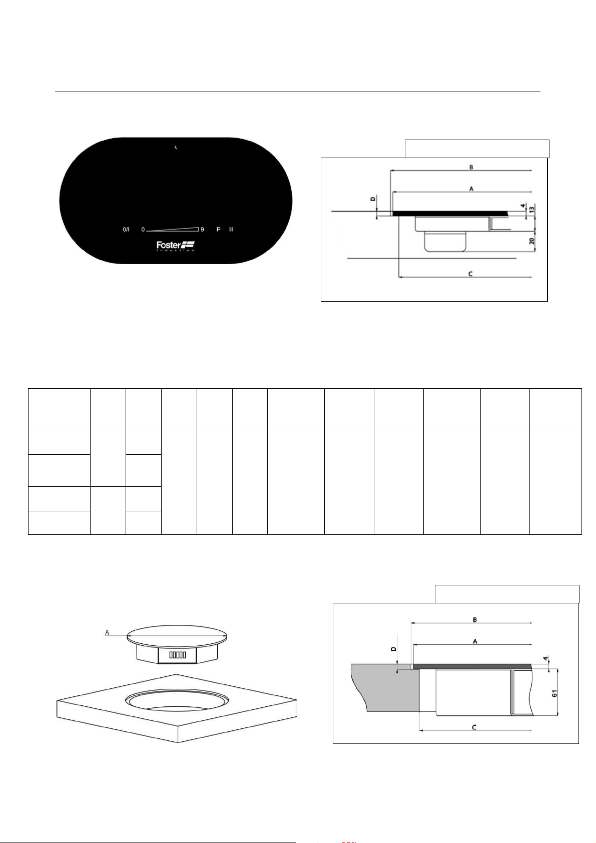
DESCRIPTION OF THE APPLIANCE
Cut out
Q4 border
Touch Control Panel
Dimensions of the control panel and cut out:
Cut out for
Flushmount
Border (mm)
B
279 x 154
R77
Product code
73 68 030
73 68 040
73 68 035
73 68 045
Color
Black
White
N°
Zones
3
4
3
4
Length
(mm)
A
275 150 75
Width
(mm)
Radius
(mm)
Depth
(mm)
D
5 4
Thickness
glass (mm)
EXAMPLE OF FLUSHMOUNT
Cut out for
Flushmount
Border (mm)
C
265 x 140
R70
Cut out for
(mm)
190 x 120
Tot.
Thickness
(mm)
37
Induction Plates:
Dimensions of the Induction Plates and cut out:
EXAMPLE OF FLUSHMOUNT
Page 4

Product code
Diameter
Thickness
Cut out
Cut out
Cut out
Tot.
73 61
270 / 73 61 275
73 62
300 / 73 62 305
73 63
350 / 73 63 355
Product code
Dimensions (
excluding t
he
N° Zones
Power (W)
73 69 030
73 69 040
Example of connection
box 4 zone
s
(mm)
A
270
300 304 284
350 354 334
Connection box:
Dimensions of the box
connectors)
(mm)
270 x 210 x 48 mm 3 5800
270 x 210 x 48 mm 4 7400
glass
(mm)
4
Flushmount
Border (mm)
B
274
Depth
(mm)
D
5
Flushmount
Border (mm)
C
Thickness
(mm)
254
65
MULTIZONES INSTALLATION
Installation
• Unpack all the materials.
• The installation and connection of the appliance have to be carried out by an
approved specialists. The manufacturer cannot be held responsible for damages
caused by errors during installation or connection.
• In order to work properly this appliance must be installed properly on an approved
and appropriate worktop.
• This appliance is for domestic use and exclusively for the cooking of food, any other
domestic, commercial or industrial use is not appropriate.
Page 5

• Before proceeding remove all labels and adhesives from the ceramic glass.
• Do not alter or modify the appliance.
• It is very important that the cooking zones and the control panel are not used as
support or worktop.
•
The appliance must be installed and connected in accordance with local safety
standards and no extension cables should be used
• The appliance cannot be installed above a dishwasher or dryer. The steam may
damage the electronic appliances.
• If the appliance is installed above an oven this must have a cooling fan.
Furthermore there must be an insulation panel between the apparatus and oven to
avoid the heating of the electrical components of the cooker.
Ventilation
Important: the cooling system needs constant airflow. Please maintain a space of at least
50mm under the induction plates to guarantee a constant airflow: See the below drawing
as an example.
Page 6

Installation instructions
The installation must be carried out by a specialized technician.
The installer must respect the local norms and standards in use.
Installation:
• The worktop or support on which the hob is installed, along with all the materials
installed must be able to resist to temperatures of up to 100 °C.
• The nearby walls and edges must also be able to resist to high temperatures.
• The hobs are classified as “Y” class for heat protection. Ideally the hob should be
installed with plenty of side space on either side to allow air circulation. In the case
of a rear and side wall make sure the opposite sides are clear from any wall,
unit or divider, mobile or immobile, with a height superior to the installation
surface of the cooker hob.
• Ensure that there is a distance of 50 mm between the hob and the wall or edges.
• Some materials which are often used to make worktops tend to expand when in
contact with water. Attention must be used for the installation of the gasket
supplied with the apparatus. The main function of these gasket is to prevent that
spilled liquids flow to the below cabinets. This gaskets guarantees the maximum
protection in combination with a smooth work tops.
• The safety gap between the hob and the cooker hood placed above the apparatus
must respect the indications of the hood manufacturer. In case of absence of
instructions please maintain a minimum distance of 650 mm.
• The connection cords should be not be tense or subject to solicitation or friction, for
example near a drawer.
CONNEXION OF THE DIFFERENT ELEMENTS
The installation of this appliance and the connections of the electrical network should be
carried out by a specialised technician in respect with the local norms and standards in
use.
Connection of cooking zones
Each connector of each cooking zone, is identified by a sticker with a number from
5 to 8 which corresponds to the following:
• 5: Heating zone 1100 W / Glass diameter 270mm (code 736127*)
• 7: Heating zone 2300 W / Glass diameter 300mm (code 736230*)
• 8: Heating zone 2300 W / Glass diameter 350mm (codice 736335*)
• The control panel is identified with the letter “C” on the connector
On the junction box, you can find the female connectors with the corresponding units: 5-67-8-C.
Page 7

The cords of the connector c
induction plates
(see the belo
corresponding number of the ju
Connect the cable of the contro
Combinations of cook
(product
1 zone 5 (mandatory) (in
2 remaining zones (indu
(codice
2 zone 5 (mandatory) (in
indu
Nota:
-
It is
strictly forbid
We do not take
manual and/or safe
Connect the hea
the wire
s
of the cooking zones.
the
Touch control 3 zone:
-
-
Touch control 4 zone:
-
-
2 remaining zones (
Example:
ction plate code 736127*)
40)
5, 7, 8)
-
Page 8

INITIAL CONFIGURATION
The apparatus must be configured before the first use following the below instructions:
I) Important
II) Disconnect the appliance from the grid by removing the fuse or turning the circuit
breaker off
III) Reconnect the table to the grid
IV) Procedure:
* Take a pot with a ferromagnetic bottom with a minimum diameter of 16 cm
* start the procedure within 2 minutes after reconnecting the hob to the grid
* don’t use the [ 0/I ] button
V) First step: cancel the existing configuration
1) Press and hold the n°2 button
2) The symbol [ . ] will appear on each display
3) With your other hand, press in succession and
quickly (less than 2s) each [ . ] display.
Begin from the front right side and turn counter
clockwise, as described in the picture (a -> b -> c -> d)).
A double "beep" means an error occurred. If so, start again from point 1).
4) Remove your fingers from the touch control, then push and hold button 1
few seconds, until the blinking [ E ] symbols appear.
5) Wait until [ E ] symbols stop blinking.
6) After few seconds, [ E ] will automatically become [ C ] confirming that the
previous configuration was cancelled.
Note: For induction hobs with 3 cooking zones, because the right front zone doesn’t
exist, begin the procedure with the right rear zone (b).
VI) Second step: new configuration
1) Take a pot with a ferromagnetic bottom with a minimum diameter of 16 cm.
2) Select a cooking zone by pushing on the corresponding [ C ] display
3) Place the pot on the area that needs to be configured
4) Wait until the [ C ] display becomes a [ - ]. The selected cooking zone is now
configured.
5) Follow the same procedure for each cooking zone with a [ C ] display.
6) All the cooking zones are configured once all the displays are turned off.
Note: Please use the same pot for the whole procedure.
Never put several pots together on the zones during the setup-process.
! Before you start, make sure there is no pot on the hob
for
WHAT TO DO IN CASE OF A PROBLEM
The symbol [ E4] appears :
• Reconfigure the table as above from step one
• If the symbol remains, please contact our After sales service
Page 9

ELECTRICAL CONNECTION
• The installation of this appliance and the connections of the electrical network
should be carried out by a specialised and qualified technician in respect with the
local norms and standards in use.
• After installation an adequate protection of the tense pieces must be guaranteed
• The necessary connection details can be found on the label near the connection
box.
• The connection to the main plug must be made using a grounded plug or via an
omnipolar circuit with a fuse block with an opening of at least 3 mm.
• The electrical circuit must be separated from the network through appropriate
devices, such as fuses, or circuit breakers.
• If the appliance is not fitted with an accessible plug, a disconnection apparatus
must be used during installation
• The power cable must be positioned so that it does not come in contact with any of
the hot parts of the hob or oven.
Caution!
This appliance must only be connected to an electric network of 230 V~ 50/60 Hz.
Always ground the plug.
Respect the connection diagram.
The terminal is located at the back of the apparatus (box). To open the cover use a
medium screwdriver. Unscrew and open the cover.
Mains Connection Cable diameter Cable Protection fuse
230V~ 50/60Hz 1 Phase + N 3 x 2,5 mm²
400V~ 50/60Hz 2 Phases + N
* calculated with the simultaneous factor following the standard EN 60 335-2-6/1990
Important
It is strictly forbidden to lengthen or shorten the wires of the cooking zones ( 5,6,7,8;)
Only the wire of the control panel (C) may be extended (Using our prolonged wire ref.
A10506/0).
Connection of the hob
Setting up the configurations:
For the various connections, use the brass jumpers which are in the box near the terminal
4 x 1.5 mm²
H 05 VV - F
H 05 RR - F
H 05 VV - F
H 05 RR - F
25 A *
16 A *
Monophase 230V~1P+N
Insert the 1st jumper between terminals 1 and 2 and the 2nd between 3 and 4.
Attach the ground plug to the terminal “earth”, the neutral N to terminal 3 or 4, and L to
either terminal 1 or 2.
Biphase 400V~2P+N
Page 10

Insert the jumper between terminals 3 and 4.
We cannot be held responsible for any incident resulting from
the
incorrect connection
of
Attach the ground plug to the terminal “earth”, the neutral N to terminal 3 or 4, the Phase
L1 to the terminal 1 and the Phase L2 to the terminal 2.
Caution! Make sure to have carefully secured the cables and jumpers and tightened
the screws
the apparatus, including the use of an apparatus that has not been grounded properly or
one that has a defected grounding system.
 Loading...