

Page 1
INSTRUCTION MANUAL
MANUEL D’INSTRUCTIONS
Cooktops - Table de cuisson
code:
7216 942
7217 942
7055 962
7245 962
7637 900
7647 900
7638 900
7648 900
7639 900
7649 900
7640 900
7650 900
EN p. 3
FR p. 21
Page 2

Page 3
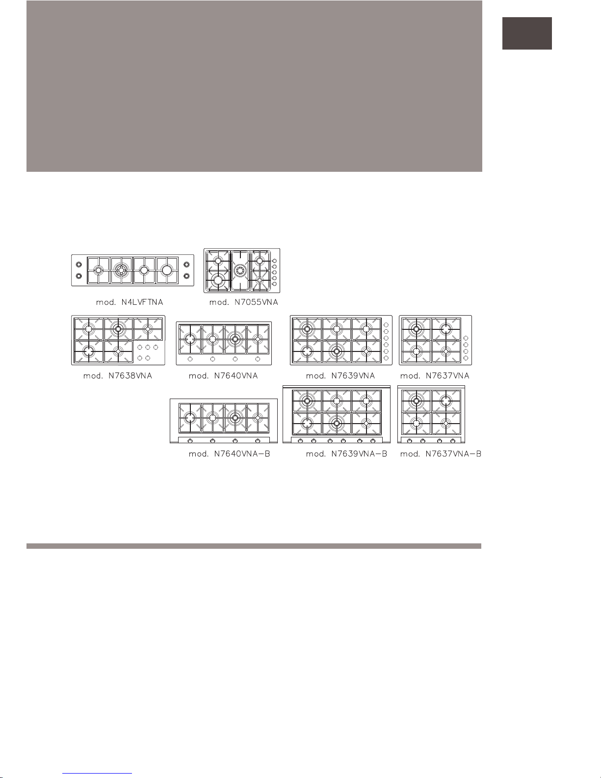
COOKTOPS MODELS
index:
Installation instructions pag. 6
Maintenance pag. 18
Warranty pag. 19
EN
Page 4

-4-
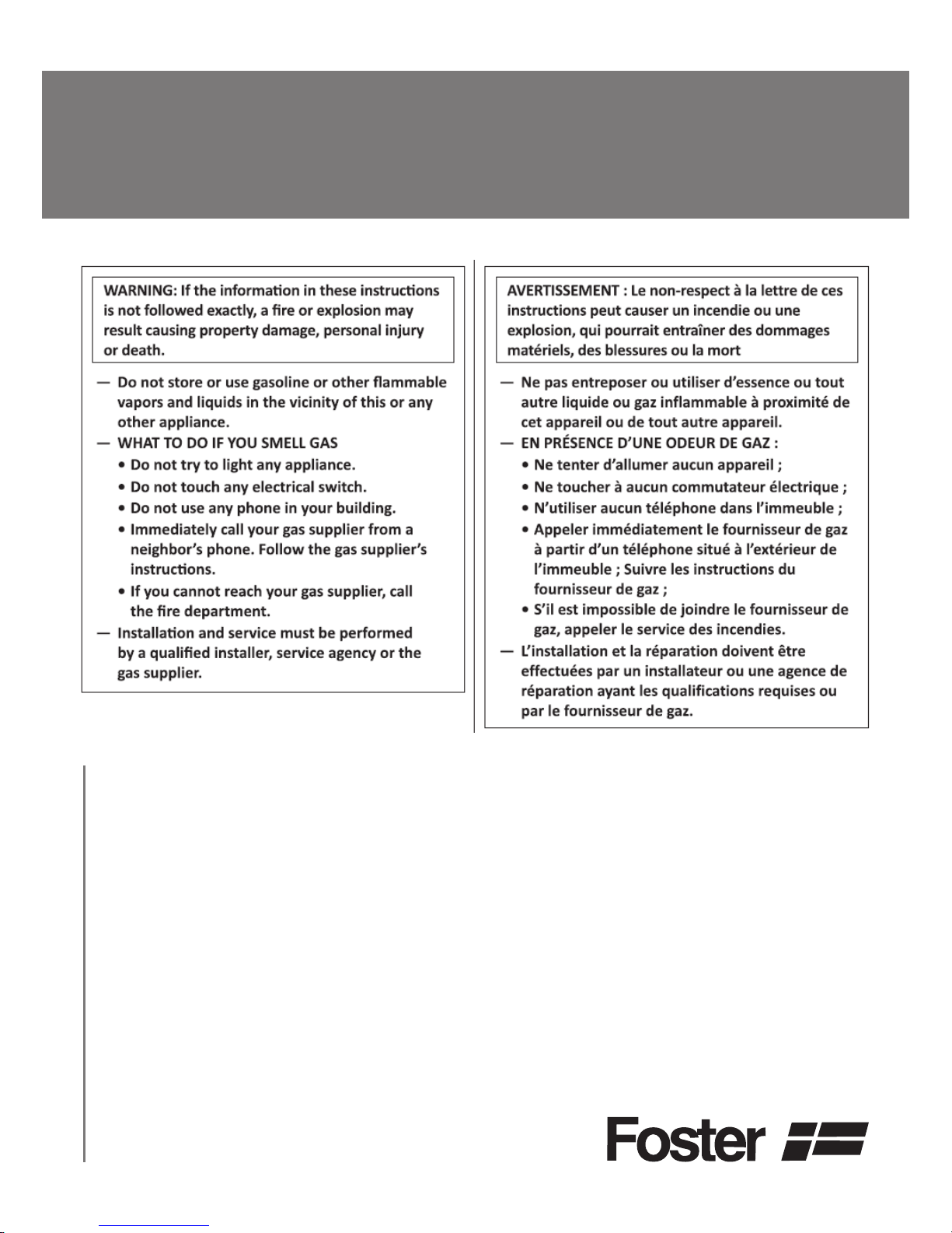
IMPORTANT SAFETY INSTRUCTIONS
Important: keep these instructions for future need.
Read and follow all instructions before using this appliance to prevent the potential risk of
re, electrical shock, personal injury or damage to the appliance as a result of improper
usage of the appliance.
IMPORTANT SAFEGUARDS
Proper installation. Be sure your appliance is properly installed and grounded by a qualied
technician.
Never use your appliance for warming or space heating. This information is based on safety
considerations.
Do not leave children and pets alone. Children and pets should not be left alone or unattended
in area where appliance is in use. They should never be allowed to sit or stand on any part of
the appliance.
Wear proper apparel. Loose tting or hanging garments should never be worn while using the
appliance. In the event that personal clothing catches on re, DROP AND ROLL IMMEDIATELY to extinguish ames.
User servicing. Do not repair or replace any part of the appliance unless specically recommended in the manual. All other servicing should be referred to a qualied technician.
Storage in or on appliance.
Flammable materials should not be stored on or near surface units.
Do not use water on grease res. SMOTHER FLAMES with a close-tting lid or other metal tray,
then turn off the gas burner. BE CAREFUL in order to prevent burns. If the ames do not go
out immediately, EVACUATE AND CALL THE FIRE DEPARTMENT. NEVER use water or a wet
dishcloth or towel on grease res: a violent steam explosion may result. Use dry chemical or
foam-type extinguisher.
Use a re extinguisher only if:
• you have a class ABC extinguisher, and know how to operate it;
• the re is small, and conned to the area where it origi
nally started;
• you can ght it with your back to the exit
• the Fire Department has already been called
Use only dry potholders. Moist or damp potholders on hot surfaces may result in burns from
steam. Do not let potholder touch heating elements. Do not use a towel or other bulky cloth.
Use proper pan size. This appliance is equipped with one or more gas burners of different
size. Select pans having at bottoms large enough to cover the burner ame area. The ame
should NOT extend beyond the bottom of the pan. Beware that direct contact with the ame
may result in ignition of clothing. Proper relationship of pan to burner size will also improve
efciency.
Page 5

-5-
Never leave surface units unattended at high heat settings. Boilovers causes smoking and greasy
spillovers that may ignite.
Protective liners. Do not use aluminium foil to line surface unit drip bowls, except as suggested in the manual. Improper installation of these liners may result in a risk of electric shock,
or re.
Glazed cooking utensils. Only certain types of glass, glass/ceramic, ceramic, earthenware, or
other glaze utensils are suitable for cooktop service without breaking due to the sudden change in temperature.
Utensils handles should be turned inward and not extended over adjacent surface units. To reduce
the risk of burns, ignition of ammable materials, and spillage due to unintentional contact
with the utensil, the handle of a utensil should be positioned so that it is turned inward, and
does not extend over adjacent surface units.
Do not touch surface units or areas near units. Surface units may be hot even though they are
dark in colour. Areas near surface units may become hot enough to cause burns. During and
after use, do not touch, or let clothing or other ammable materials contact surface units or
areas near units until they have had sufcient time to cool. Other surfaces of the appliance
may become hot enough to cause burns. Among these areas and surfaces are the cooktop and
surfaces facing the cooktop.
Do not heat unopened food containers. Build-up of pressure may cause container to burst result
in injury.
Clean ventilating hoods frequently. Grease should not be allowed to accumulate on hood or lter
(when a cooking hood is installed with appliance).
In case of re, if the hood is functioning TURN IT OFF. The fan, if operating, may spread the
ame.
CALIFORNIA PROPOSITION 65 - Warning: burning gas cooking fuel generates by-products which
are on the list of substances known by the State of California to cause cancer or reproductive
harm. In order to minimize exposure to these substances, be careful to always operate this
appliance in accordance with the instructions contained in this manual and provide proper
ventilation.
WARNING: This appliance should not be installed with a ventilation system that blows air
downward toward the appliance. This type of ventilation system may cause ignition and combustion problems with the gas cooking appliance resulting in personal injury or unintended
operation.
WARNING Air curtain hoods or other overhead range hoods, which operate by blowing a
downward airow downward towards the appliance, shall not be used in conjunction with this
gas appliance unless the hood and range have been designed and tested in accordance with
the Standard for Domestic Gas Ranges ANSI Z21.1 – CSA1.1 and listed by an independent
testing laboratory for combination use.
CAUTION: Do not store items of interest to children in cabinets above cooktop or on
the backguard of a cooktop, children climbing on the cooktop to reach items could be
seriously injured.
!
Page 6
-6-
INSTALLATION INSTRUCTIONS
SPECIAL WARNING:
Only qualied personnel should install or service this cooktop. Read “safety instructions”
in this book before using cooktop. Improper installation, adjustement, alteration, service,
maintenance or use of the appliance can result in serious injury or property damage.
Installation must conform with local codes or, in the absence of codes, the National Fuel
Gas Code, ANSI Z223.1 / NFPA 54 or latest edition. In Canada, installation must be in
accordance with the current CAN/CGA B149.1 & 2 Gas Installation Codes and/or local
codes.Electrical installation must be in accordance with local codes or, in the absence
of local codes, with the National Electric Code ANSI/NFPA n. 70 - latest edition. In
Canada, the current CSAC22.1 Canadian Electrical Code part 1 and/or local codes.
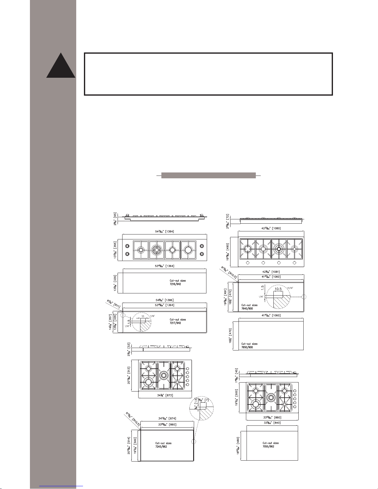
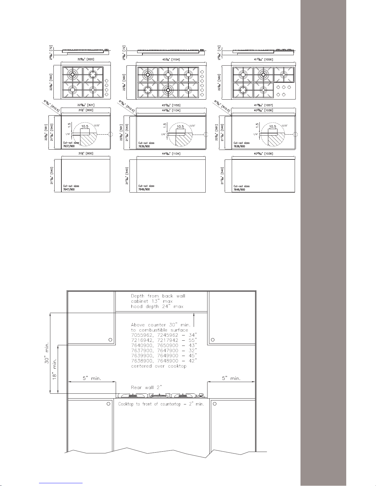
CLEARANCE DIMENSIONS
For complete information regarding the installation of wall cabinets above the cooktop
and clearances to combustible wall above the cooking top see the installation drawing
(allow 5” clearance under cooktop for gas connection):
!
Page 7
-7-
Instructions are based on Standard American cabinets 36” high x 24” deep with a 25” countertop. 13” maximum depth for cabinets installed above cooktop.
For safety considerations do not install a cooktop in any combustible cabinetry which is
not in accord with the installation drawing. Minimum dimension between cooktop and
wall cabinet is 30” (see g. 1).
Fig. 1
Dimensions
are minimum
clearances to
combustible
materials
Page 8
-8-
The 30 inch (76 cm) dimension may be reduced to not less than 24 in (61 cm) when
the wall cabinets in a domestic home are protected with reproof materials in accordance with American National Standards - National Fuel Gas Code. To eliminate the risk of
burns or re by reaching over heated surface units, cabinet storage space located above
the surface units should be avoided. If cabinet storage is to be provided, the risk can
be reduced by installing a range hood that projects horizontally a minimum of 5 in (13
cm) beyond the edge of the cabinets. Minimum distance between the cooktop and the
rear wall is 1” ¾. Minimum distance between the front edge of the counter and the
cooktop’s front edge is 2”.
CAUTION:
Some cabinets and building materials are not designed to withstand the heat
produced by the normal safe operation of a listed appliance. Discoloration or damage, such
as delamination, may occur.
LOCATING THE COOKTOP
Do not set cooktop on locations where it may be
subject to strong drafts. Any opening in the wall
behind the cooktop should be sealed. Make
sure the ow of combustion or ventilation air is
not obstructed.
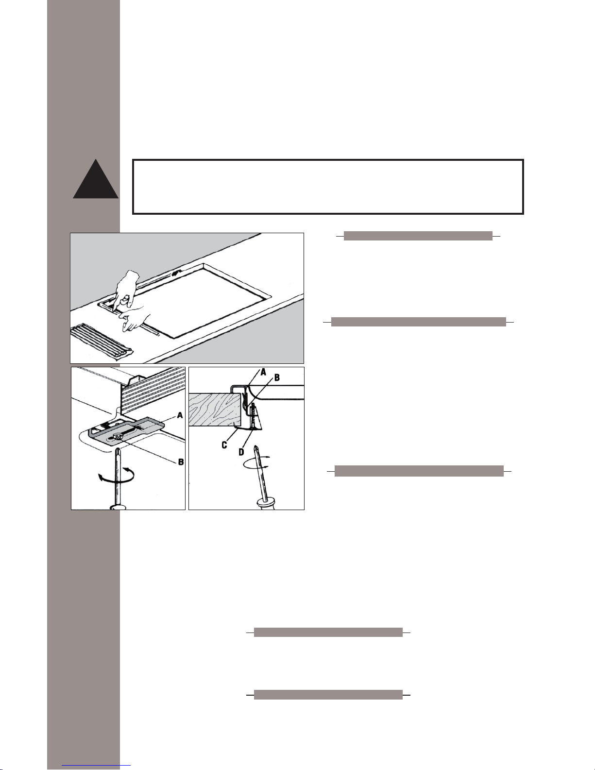
FIXING THE COOKTOP TO COUNTERTOP
A kit of sealing gasket is supplied within the
cooktop package. Install the sealing gasket
around the top surface of the cut-out perimeter.
This sealing gasket prevents liquids from
leaking under the cooktop.
NOTE: Do not use caulk or silicon to x cooktop
to countertop. The cooktop must be readily removable for service.
COOKTOP CLAMP DOWN INFORMATION
Before unit is installed in counter opening, you
must apply supplied xing brackets to cooktop.
Insert bracket with offset side of angle into underneath cover slot on front and back side of unit. Put in place xing screw, without
tightening, so the bracket can slide in and out. Keeping brackets slid-in, install cooktop
in counter opening. Once units is installed, clamp down cooktop by sliding out xing
brackets and placing its external tip on counter underneath surface, then tighten screws
slightly (over tightening may cause damage to cooktop) till unit is rmly blocked.
Once cooktop is xed in place, remove sealing gasket excess by using a cutter or a sharp
edge tool. IMPORTANT for solid surface material installation: please insert a wooden
block between the clamp and the bottom of the countertop.
VENTILATION
Ventilation must be in accordance with local installation code. The appliance must
be installed in a well-ventilated environment to guarantee a correct combustion gas
exchange, proper air circulation and working temperature within safety limits.
MODEL NUMBER PLATE
The model number plate is located on the bottom case of the cooktop. A second model
number plate is applied on the front page of the instruction booklet.
!
Page 9
-9-
ELECTRICAL INSTALLATION
AND CONNECTION
WARNING.
ELECTRICAL GROUNDING INSTRUCTIONS
The cooktop must be electrically grounded in accordance with local codes or, in the absence
of local codes, with the National Electric Code ANSI/NFPA n. 70 latest edition. Installation
should be made by a licensed electrician.
WARNING
: This appliance is equipped with a (three-prong) grounding plug for your protection against shock hazard and should be plugged directly into a properly grounded receptacle. Do not cut or remove the grounding prong from the plug.
!
If you have any doubt as to whether the wall receptacle is properly grounded, you should
have it checked by a qualied electrician. If an ungrounded, two-hole or other type of
electrical outlet is encountered, it is the personal responsibility of the appliance owner
to have the outlet replaced with a properly grounded three-hole electrical outlet. This
should be done by a licensed electrician.
The appliance must be connected to a single-phase 120 Vac 60 Hz 15 amps electrical
outlet.
CAUTION: Before you plug in an electrical cord, be sure all controls are in the OFF position.
The cable cord connected to the cooktop, is a exible type of cable. Pass it through the
hole prepared in the cabinet to plug it to wall socket located under the cooktop area
cabinet. To facilitate service, the ex cable must not be shortened and should be routed
to permit temporary removal of the cooktop.
!
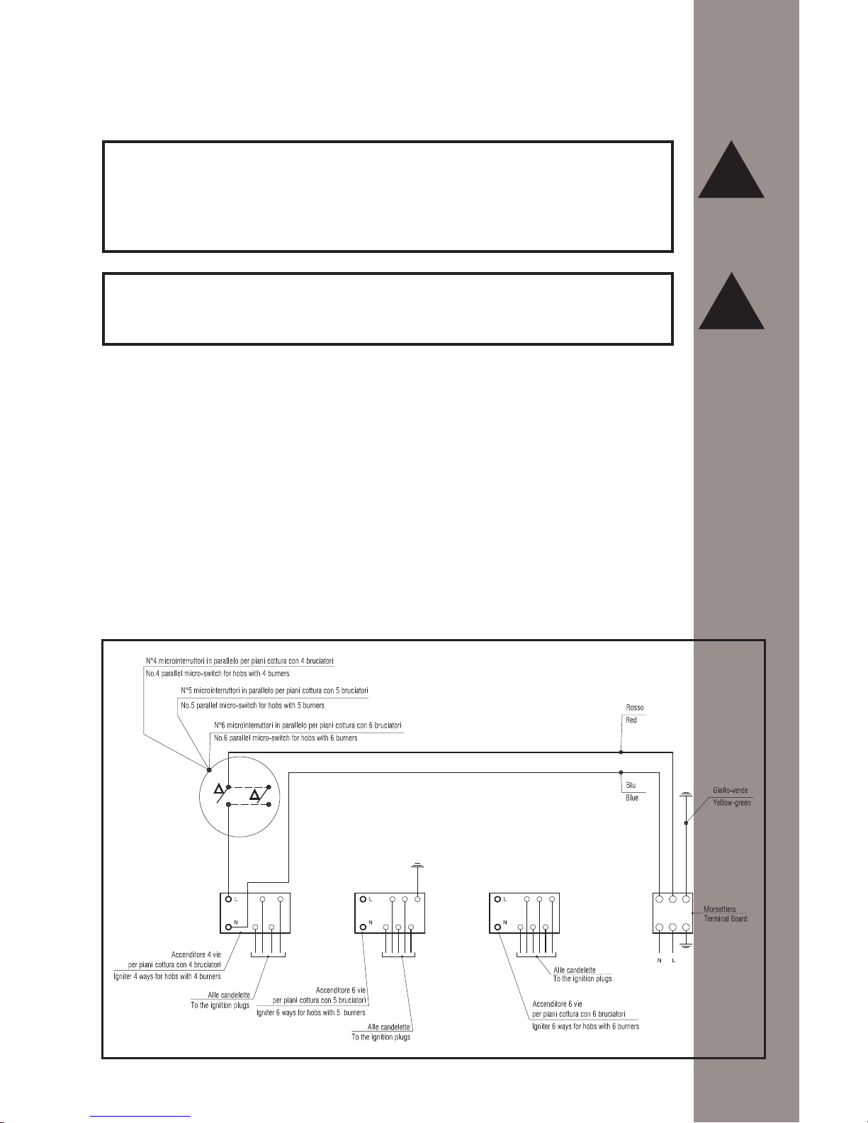
Electrical diagrams
Page 10
-10-
WARNING
Disconnect electrical supply before servicing the appliance.
When the exible cord has to be changed it is necessary to follow the procedure described hereafter:
- Turn off main gas shut-off valve and disconnect electrical supply
- Pull out entire cooktop from the counter by loosing the xing brackets
- Disconnect gas supply connector from cooktop manifold
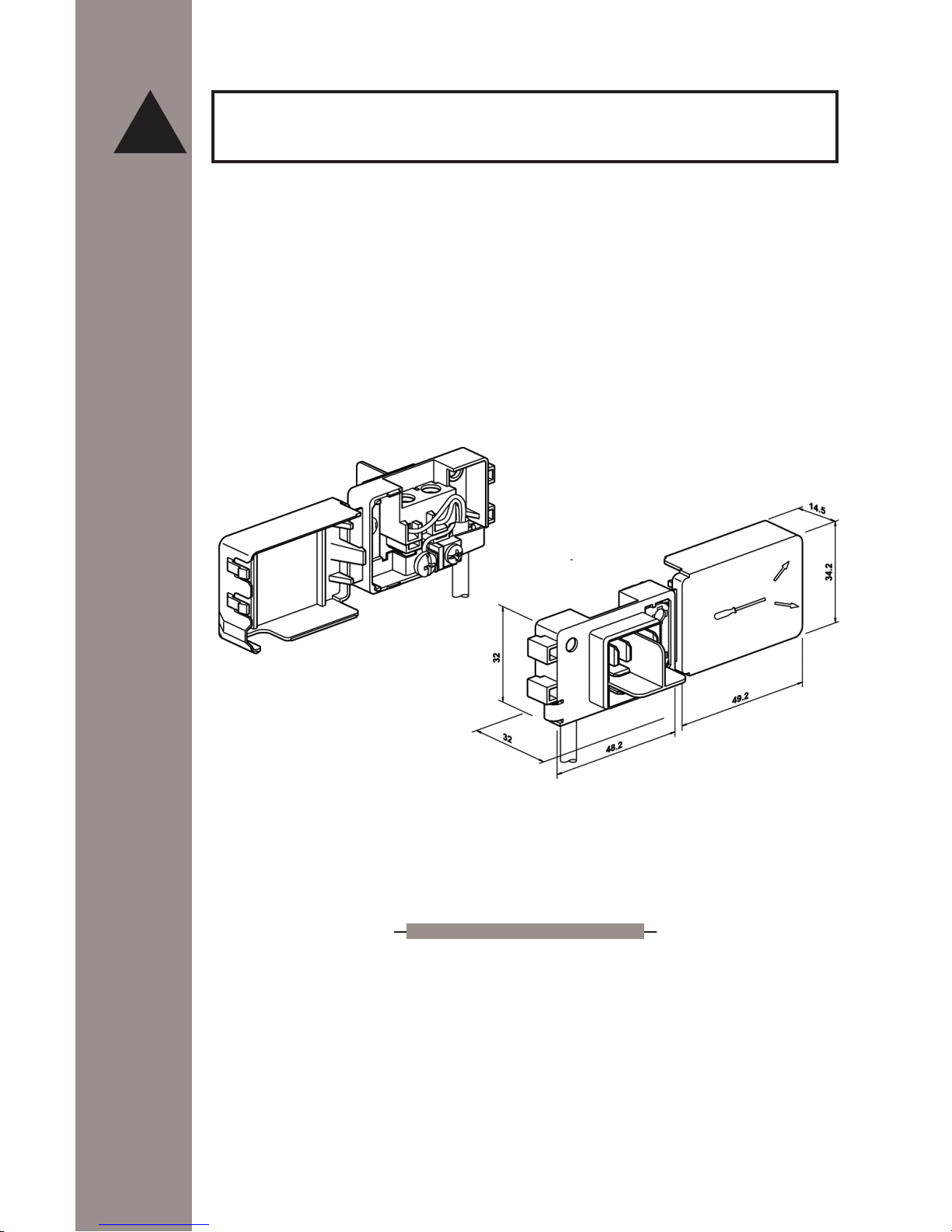
- Open un connecting terminal block cover, see g. 2
- Open exible cord lock and loosen the old cord prongs from terminal block
- Connect new exible cord prongs to terminal block and x exible cord lock, remembering that the earth wire (green) must be longer by one inch than the other ones. For
Line and Neutral wire connection, follow signs on terminal block
- The exible cord must be hold tight by the cord lock, in such a way that it may not
be pulled out. The exible cord path must not be in proximity or in contact with hot
surfaces that may damage the cord itself.
ATTENTION: The exible cord must be in accordance with National Electrical Codes and
suitable for the hob technical characteristics electrical ratings. A 18 AWG three-prong grounding plug exible cord, type SJT3x18AWG.
THE MANUFACTURER DECLINES ANY RESPONSIBILITY FOR IMPROPER INSTALLATION, ADJUSTEMENT, ALTERATION, SERVICE, MAINTENANCE OR USE OF THE APPLIANCE, WHICH MAY
RESULT IN SERIOUS INJURY OR PROPERTY DAMAGE.
GAS SUPPLY
Installation of this cooktop must conform with local codes or, in the absence of local
codes, with the National Fuel Gas Code, ANSI Z223.1/NFPA 54 latest edition.
In Canada the cooktop must be installed in accordance with the current CGA Standard
CAN/CGA-B149 - Installation Codes for Gas Burning Appliances and Equipment and/or
local codes.
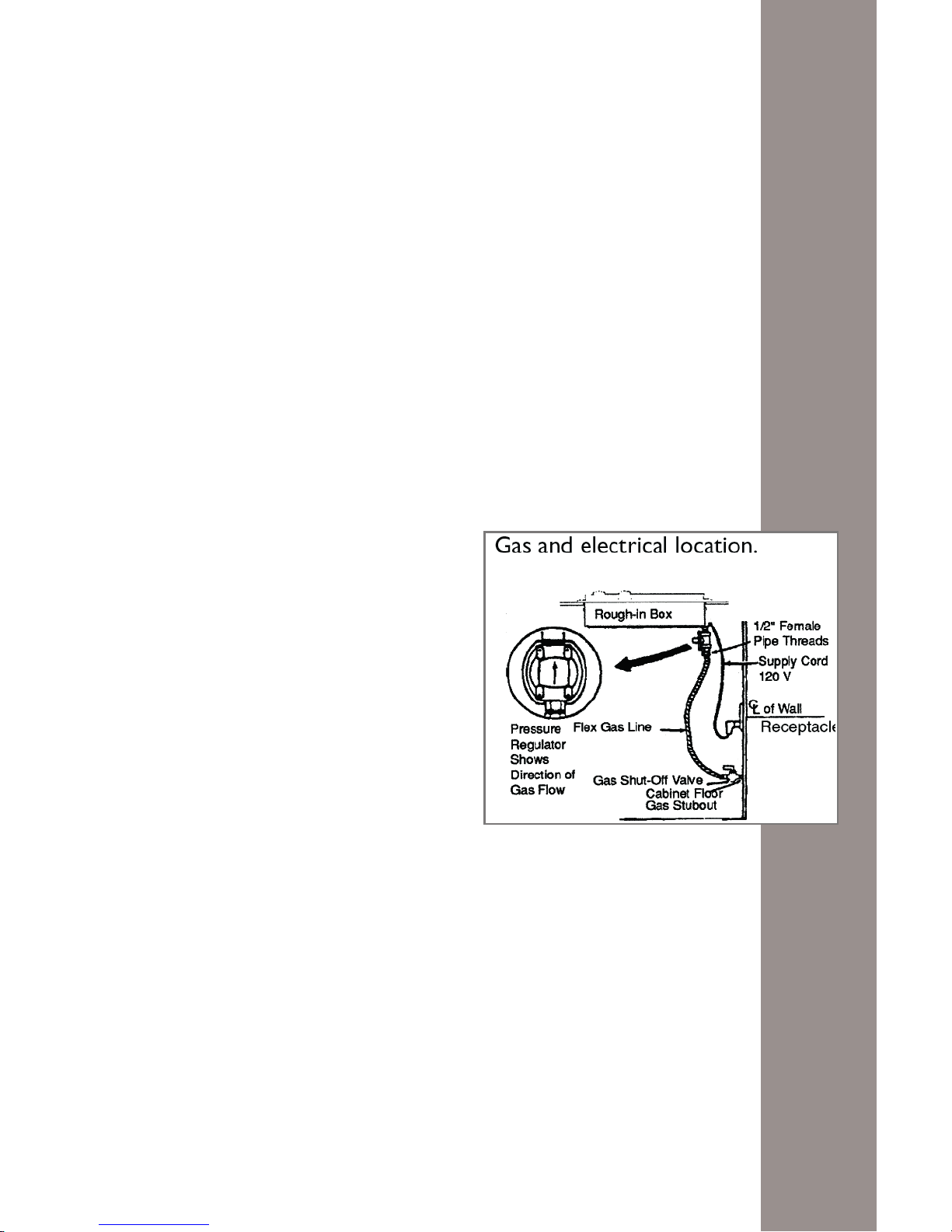
GAS SUPPLY CONNECTION:
A TRAINED SERVICEMAN OR GAS APPLIANCE INSTALLER MUST MAKE THE GAS SUPPLY CONNECTION.
Leak testing of the appliance shall be conducted by the installer according to the instructions
given in this section.
This appliance should be installed and used with the supplied pressure regulator. Inlet
!
Fig. 2
Page 11
-11-
pressure to the regulator should not exceed 4 in. w.c. for use with natural gas, and 11
in. w.c. for use with LP gas.
Inlet pressure in excess of 14 in. w.c. can damage the appliance pressure regulator, or
other gas component in this appliance and can result in a gas leak.
a) A gas cut-off valve should be put in an accessible location in the supply line
ahead of the cooktop, for turning on and turning off gas supply. If cooktop is to
be connected to house piping with exible or semi-rigid metal connectors for gas
appliances, connectors nuts must not be connected directly to pipe threads. The
connectors must be installed with adapters provided with the connector.
b) The house piping and/or cooktop connector used to connect the cooktop to the
main gas supply must be clean, a free of metal shavings, rust, dirt and liquids
(oil or water). Dirt in the supply lines can work its way into the cooktop manifold
and in turn cause failure of the gas valves or controls and clog burners and/or
pilot orices.
c) Turn off all pilots and main gas valve of other gas appliances.
d) Turn off main gas valve at meter.
e) Before connecting cooktop apply pipe thread compound approved for LPG to all
threads.
f) After installing a gas shut-off valve in an
easily accessible location under the unit
(see g. 3), install the pressure regulator
(supplied) to manifold pipe using Teon®
tape on threads of manifold pipe. To prevent possible damage to the gas pressure
regulator, install it after the rough-in box
is in its permanent position.
CAUTION: do not attempt any adjustment
of the pressure regulator, except conversion to propane. Connect the gas supply
line to the unit pressure regulator using a
1/2” ex gas line connector between wall
shut-off valve and pressure regulator (see
complete procedure in g. 3).
g) After installing the pressure regulator, the installer must check the manifold
pressure; this can be done by connecting a proper metering device to the 1/8
NPT thread directly on the pressure regulator.
h) For model 7216 942 - 7217 942: this cooktop has two manifold gas inlet (one
on the far right and one on the far left of the cooktop): two separate pressure regulators are supplied, and must be installed, one on each side, as per procedure
described in point f) of this paragraph.
i) See rating plate for type of gas the cooktop has been manufactured for.
j) Turn on main gas valve at meter, and relight pilots at other gas appliances.
k) Apply a non-corrosive leak detection uid to all joints and ttings in the gas
connection between the supply line shut-off valve and the cooktop. This includes gas ttings and joints in the cooktop if connections were disturbed during
Fig. 3
Page 12
-12-
installation. Check for leaks! Bubbles appearing around ttings and connections
will indicate a leak. If a leak appears, turn off supply line gas shut off valve, and
retest for leaks.
CAUTION: NEVER CHECK FOR LEAKS WITH A FLAME. WHEN LEAK CHECK IS
COMPLETE, WIPE OFF ALL RESIDUE
l) Remove shipping polystyrene from ALL cooktop burners. The polystyrene is
meant to hold the burners in place on the burners’ base, and should be used for
shipping purposes only.
CHECKING THE BURNERS’ INSTALLATION
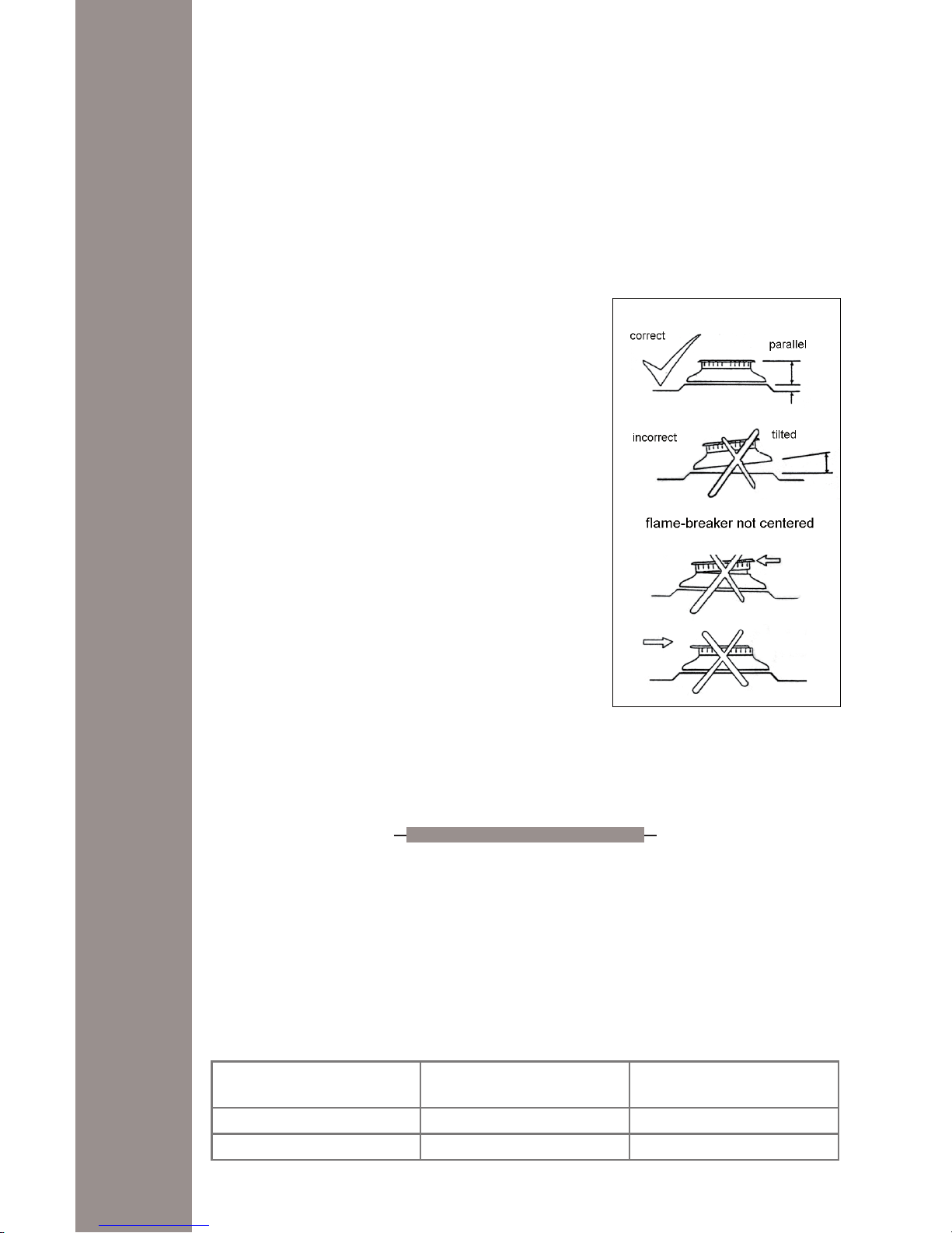
Make sure that the burners and burner covers are properly positioned, that they t into each-other securely,
and that they are perfectly horizontal (see g. 4).
CHECKING PRESSURE OF HOUSE PIPING SYSTEM
1) The appliance and its individual shutoff valve
must be disconnected from the gas supply piping system during any pressure testing of that
system at test pressure in excess of ½ psi.
2) The appliance must be isolated from the gas
supply piping system by closing its individual
manual shutoff valve during any pressure testing of the gas supply piping system at test
pressure equal to or less than ½ psi.
GAS CONVERSION
All cooktops are equipped with both Natural Gas and LP gas injectors as well as a
convertible pressure regulator. The unit model number plate states which gas it was
adjusted for at the factory. To convert the unit to either Natural gas or LP gas one should
t the proper burner injectors, adjust the burners for low ame and adjust the pressure
regulator converter cap.
Inlet pressure to the appliance pressure regulator should be as follows for both operation
and checking of appliance pressure regulator setting:
MANIFOLD PRESSURE
Fig. 4
Gas
Pressure in inches
of water column
Pressure in kPa
Natural gas 4 1
LP gas 11 2.7
Page 13

-13-
GAS BURNER INJECTOR CONVERSION
Before proceeding with the conversion, shut off the gas supply to
the appliance prior to disconnecting electrical power. To switch
injectors, one should unscrew the installed injector using a proper
7mm hex. key tool and replace it with new injector for new gas setting (g. 5). Save the injectors removed from the appliance for fu-
ture use. The proper injector for each burner
has a different hole diameter. Please check
the chart at page 15 for proper nozzle size
for each burner. The diameter of the nozzle
is engraved on the side of the nozzle itself.
Should the engraving prove difcult to read,
please use a magnier. Please note that the
conversion should be performed by a qualied technician, following the manufacturer’s
instructions. After performing the conversion,
the technician must test the appliance for leaks, following the instructions given in “GAS
SUPPLY CONNECTION”.
WARNING
This conversion kit shall be installed by a qualied service agency in accordance with
the manufacturer’s instructions and all applicable codes and requirements of the
authority having jurisdictions is not followed exactly, a re, explosion or production of
carbon monoxide may result causing property damage, personal injury or loss of life.
The qualied service agency is responsible for the proper installation of this kit. The
installation is not proper and complete until the operation of the converted appliance
is checked as specied in the manufacturer’s instructions supplied with the kit.
APPLIANCE PRESSURE REGULATOR CONVERSION
The unit appliance pressure regulator must be set to match the type gas supply used. If
converting from natural gas to LP gas, the appliance pressure regulator must be converted to regulate LP gas. If converting from LP gas to natural gas, the appliance pressure
regulator must be converted to regulate natural gas.
To convert the appliance pressure regulator from one gas to another: remove the cap,
push down and turn counter-clockwise. Turn the cap over and reinstall it, follow the NAT
or LP indication (g. 6).
NOTE: THE GAS TYPE YOU ARE CONVERTING TO MUST BE VISIBLE ON THE TOP OF
THE INSTALLED APPLIANCE PRESSURE REGULATOR CAP.
Pressure regulator
natural/town gas adjustment
(low outlet pressure)
Fig. 6
ATTENTION
The regulator is pre adjusted
for both values. Aside from
the turning of the plug (1),
there is no further customer
adjustment necessary.
Pressure regulator lpg
adjustment
(high outlet pressure)
Fig. 5-A
Fig. 5-B
Page 14

-14-
SERVICE - PARTS INFORMATION
When your cooktop requires service or replacement parts, contact your dealer or authorized service agency. Please give the complete model and serial number of the cooktop
which is located on the cooktop model number plate.
Should you fail to locate the required replacement parts locally, please contact the
Nationwide service organization (for Canada and the U.S.A.):
Foster Service Center
7575 E Redield Rd #129, Scottsdale, AZ 85260
Telephone (888) 639-6001
E-mail: foster@adcoservice.com
Fax: (480)998-7877
For Massachusetts installations:
1. Shut-off valve must be a “T” handle gas cock
2. Flexible gas connector must not be longer than 36 inches
3. Not approved for installation in a bedroom or a bathroom unless unit is direct
vent
CHECK OF GAS PRESSURE AFTER THE INSTALLATION OF THE PRESSURE REGULATOR
The gas pressure in the cooktop’s manifold should be checked by a qualied installer,
after the pressure regulator has been installed and tested. To do this, a 1/8 NPT thread
is provided directly onto the pressure regulator. Connect a proper metering device to the
thread in order to measure the pressure. In order to check the pressure regulator, the
inlet pressure should be at least 1 in. water column more than the regulated manifold
pressure.
Page 15

-15-
LOW SETTING VALVE ADJUSTEMENT
The low setting should produce a stable ame when turning the knob from max to min. The ame should be
1/8 inch (3,2 mm) or lower and must be stable on all
ports on low setting. To adjust: operate burner on max for
about ve minutes to properly heat the burner itself. Turn
knob back to min; remove knob, and insert a small at
tip screwdriver into the centre of the valve stem. Adjust
the ame size by turning adjustment screw in either direction, while holding the stem to prevent it from rotating
(g. 7).
Flame must be of sufcient size to be stable on all burner ports. If ame adjustment is
needed, adjust only on the low setting. Never adjust ame size on higher setting.
When a two-way gas tap is present there are two screws for minimum gas ow adjustment.
NOTE: all gas adjustment should be done by qualied service personnel only
COOKTOP TECHNICAL DATA (7055 962, 7245 962, 7216 942, 7217 942)
Burner BTU/hr Injector (mm)
Natural Propane
Auxiliary 2.800 0,80 0,50
Semi-rapid 5.100 1,10 0,65
Rapid 7.600 1,30 0,82
Triple crown 11.000 1,60 0,95
COOKTOP TECHNICAL DATA (7637 900, 7647 900, 7638 900, 7648 900, 7639 900,
7649 900, 7640 900, 7650 900)
Burner BTU/hr Injector (mm)
Natural Propane
Auxiliary 5.000 1,05 0,63
Semi-rapid 9.100 1,45 0,86
Rapid 10.750 1,55 0,92
Double crown (inside burner)
15.500
0,90 0,53
Double crown (external crown) 1,70 1,00
To identify the right nozzle for each burner, please refer to the gure embedded on the
nozzle itself.
DIMENSIONS OF THE APPLIANCES
Mod. Width in (mm) Height in (mm) Depth in (mm)
7055 962 33
55
/
64
(860) 1
49
/
64
(45) 19
11
/
16
(500)
7245 962 34
3
/
8
(873) 2
3
/
32
(53) 20
13
/
64
(513)
7216 942-7217 942 54
31
/
64
(1384) 2
9
/
16
(65) 13
31
/
32
(355)
7637 900-7647 900 32
9
/
32
(820) 2
53
/
64
(72) 22
3
/
64
(560)
7638 900-7648 900 41
37
/
64
(1056) 2
53
/
64
(72) 22
3
/
64
(560)
7639 900-7649 900 45
7
/
16
(1154) 2
53
/
64
(72) 22
3
/
64
(560)
7640 900-7650 900 42
33
/
64
(1080) 2
53
/
64
(72) 19
19
/
64
(490)
Fig. 7
Page 16

-16-
INSTRUCTION GUIDE FOR GAS COOKTOP
For models with single action automatic ignition, place a pan on the burner grate. Push
in and turn the knob counterclockwise to the max setting. A clicking sound will be heard and the burner will ignite, g. 8. The ignitors of all the burners will spark when any
control knob is operated. Keep the knob pushed in until the burner ignites, then turn
the knob to the desired ame size, g. 9.
For models equipped with both electronic ignition and safety device, follow the same
procedure, but keep pushing in for at least 4 seconds until the thermocouple is hot
enough. Then release the knob; the burner should remain on.
If the burner does not light within 4 seconds, turn the burner off. Check to see that the
cap is positioned correctly on the burner base and the igniter is clean and dry, then try
again.
!
CAUTION:
1) Do not store or use gasoline or other ammable vapours, liquids or items in the vicinity
of this or any other appliance.
2) Do not obstruct the ow of combustion and ventilation air by blocking the room vents
or air intakes. Restriction of air ow to the gas appliance prevents proper performance
and increases carbon monoxide emission to unsafe levels.
3) Continuously use of the appliance may need extra ventilation, this can be solved by just
opening a window or increasing exhaust power of a cooking hood.
4) To prevent are ups do not use the cooktop without all burner caps properly positioned.
5) To prevent are ups all grates must be properly positioned on the cooktop whenever the
cooktop is in use. Each of the four feet must be placed into the corresponding dimples
!
Fig. 8
OFF indicator
HIGT
(MAX)
LOW (MIN)
MAX 1
MAX 2
MAX 1
MIN 2
MAX 1
OFF 2
MIN 1
OFF 2
1 INSIDE BURNER
2 EXTERNAL CROWNS
OFF indicator
Fig. 9
Burner control knobs
WARNING
NEVER use this appliance as a space heater to heat or warm the room.
Doing so may result in carbon monoxide poisoning and overheating of the cooktop.
Page 17

-17-
in the cooktop’s steel surface. Do not use a grate if the rubber feet are missing or damaged.
6) Without power supply, the cooktop won’t ignite. In this case, to ignite the cooktop, use
a match or a lighter, taking care to put the knob on the minimum gas ow position.
However, should the power supply fail during cooking, the cooktop will continue to
work properly. This means that the ame won’t go out, and that the safety thermocouple
will also continue to work properly, as they do not need electrical power to function.
However, please beware that the cooker hood may not work without power, and thus fail
to aspire the fumes.
COOKWARE
To achieve optimum surface cooking performance, select heavy gauge, at, smooth
bottom pans that conform to the diameter of the cooking area as well as straight sides.
Remember to use pans with at bottoms and handles that are easily grasped and stay
cool. To minimize burns, ignition of ammable materials and spillage due to unintentional contact with the utensil, do not extend handles over adjacent surfaces burners.
Always turn pan handles toward the side or back of the appliance, not out into the room
where they may be easily hit or reached by small children.
NOTES FOR COOKWARE ON GAS BURNERS
We recommend the following pan size for the different sizes of burner.
BURNER TYPE COOKING PAN BOTTOM SIZE
Auxiliary
from 3 in (7.6 cm) to 6 in (15.25 cm)
Semi-rapid
from 6 in (15.25 cm) to 8 in (20.3 cm)
Rapid
from 8 in (20.3 cm) to 10 in (25.4 cm)
Double crown, triple crown
from 10 in (25.4 cm) to 11 in (28 cm)
Burner operational notes (g. 10):
• A properly adjusted burner with clean ports will
light within a few seconds.
If using natural gas the ame will be blue with
a deeper blue inner cone.
• If the burner ame is yellow or is noisy the air/
gas mixture maybe incorrect. Contact a service
technician to adjust.
• With LP gas, some yellow tips on the ames are
acceptable. This is normal and adjustment is
not necessary.
• If soot is noticed on pan bottom, contact a service technician to adjust.
• The ame should not extend beyond the edge of
the pan (g. 11).
Fig. 10
RIGHT WRONG
Fig. 11
Never extend the flame beyond the outer
edge of the utensil. A higher f
lame
simply wastes heat and energy, and
increases your risk of being burned by
the flame.
Page 18

-18-
MAINTENANCE
CLEANING SAFETY
Turn off all controls and wait for appliance parts to cool before touching or cleaning
them. Do not touch the burner grates or surrounding areas until they have had sufcient
time to cool.
Clean appliance with caution. Use care to avoid steam burns if a wet sponge or cloth
is used to wipe spills on a hot surface. Some cleaners can produce noxious fumes if
applied to a hot surface.
BURNERS
Take off the removable parts and put them for 10 minutes in a soapy warm water. Eventual stubborn soils can be removed by using a nonabrasive pad or a plastic scouring
pad.
SURFACE CLEANING
This is easily done using a damp cloth and a non-abrasive detergent, wipe using a soft
dry cloth. For stainless steel parts with stubborn soils, use only plastic scrubbing pad or
a sponge with vinegar and warm water.
Because of many new cleaning products introduced in the marketplace each year, it is
not possible to list all products that can be safety be used to clean this appliance. Read
carefully the cleaner manufacturer’s instructions to be sure the cleaner can be safely
used on this appliance. To determine if a cleaning product is safe, test a small inconspicuous area using a very light pressure to see if the surface may scratch or discolour.
This is particularly important for porcelain enamel, highly polished, shiny, painted or
plastic surfaces.
ABNORMAL OPERATION
Any of the following are considered to be abnormal operation and may require servicing:
• Burner ame with yellow tips.
• Soot on pan bottom.
• Difcult burner ignition.
• Burners fail to remain lighted.
• Burner will ame out.
• Difculty in turning gas valves.
NOTES: control regularly the correct functioning of gas valves.
In case of abnormal functioning of these devices, you must immediately call a qualied
technical assistance service.
PROBLEM SOLVER
Before calling for service
• Make sure that the gas shut off valve is in the ON position and the gas supply to
the house in not shut off.
• Make sure the burner caps are properly positioned and the burner ports are not
clogged. Clear ports with a wire if clogged.
• Make sure the igniters are clean and dry.
• Make sure that there is no draft in the room.
• Check the power supply. It should be properly grounded with the correct polarity.
Check that the unit is plugged in and the circuit breaker is not tripped.
• When the electrical power connection has been activated at the rst power up or
reconnected after an outage, the igniters may spark several times even though
all burner knobs are in the off position.
!
Page 19

-19-
WHAT IS COVERED:
FOSTER guarantees its products for a period of
24 months from the date of original purchase
by nal customer. The purchase must be veried with a valid receipt issued by the dealer
(receipt, invoice or delivery note) that identies
the purchased product, date of purchase and /
or delivery of the same.
The buyer must report any esthetical defect within the rst month of purchase of the product.
The warranty covers manufacturing defects to
all components except for the external piping
and / or any accessories.
WHAT IS NOT COVERED:
• Damage caused during installation of the
product (reversing doors, removing screws or
brackets, adjusting feet, burners, etc.)
• Damage derived from the connection of the
power, gas, water and/or electricity supply.
• Damage to knobs, handles, plastic parts, removable panels, lamps, glass parts and external rubber tubes.
• Damaged caused from accident, alteration,
misuse, abuse, re, ood, acts of God, improper installation or use of products not approved by Foster.
• Damage to external components on which
the consumer may intervene directly during
use and / or maintenance, and which may be
subject to wear.
• The formation of rust and stains on the steel
due to the use of unsuitable cleaning agents.
• Any functional defect indicated by the user
and not conrmed during the process of verication by the technician. In this case the
intervention fee will be charged in full to the
consumer.
• Any parts that are Damaged from transportation
not carried out by a Foster approved carrier.
• Incorrect installation or maintenance, insufcient or excessive electrical ow, plumbing or
gas abnormalities, insufciency of the chimneys, and poor fuel quality.
• Failure to follow the Foster instruction manual.
• Repair by unauthorized personnel.
• This warranty applies to appliances used in
residential application; it does not cover their
use in commercial situations, which are not
allowed for this product.
• Travel fees and associated charges incurred
when the product is installed in a location
with limited or restricted access (i.e., isolated
geographic regions located beyond 50 miles
from the nearest Foster dealer).
• Also not included are service visits to:
a) Educate the customer in the proper use
and care of the product.
b) Correct the installation. The customer is re-
sponsible for providing electrical wiring and/or
gas installation and other connecting facilities.
c) Reset circuit breakers or replace home fuses
Should the appliance be sold by the original
purchaser during the warranty period, the new
owner continues to be protected until the expiration date of the original purchaser’s warranty
period. During the warranty period, FOSTER will
replace, or repair free of charge, all components
that are defective in origin, leaving unchanged
the deadline and the warranty acquired at the
time of purchase. The repair is free of charge provided it is carried out by an authorized
FOSTER Technical Assistance Centre. If the
equipment is repaired at one of the Authorised
Service Centres indicated by the manufacturer
and in the case of replacement of the product,
shipping will be free of charge. In cases where repair at home is declined, transport to and
from the assistance centre will not be paid for or
provided by FOSTER. Once the warrantee time
has elapsed, the warranty becomes void and assistance will be made by debiting the cost of
the replaced parts, and the costs of labour and
transportation, according to the rates in force.
Authorized technicians will be sent in due time
by FOSTER, with the desire of offering the best
service available. FOSTER is not liable for any
damages, direct or indirect, caused to people,
objects and pets for failure to follow all the instructions given in the instruction booklet and
from damages resulting from the forced suspension of the use thereof. FOSTER will not
be liable for damages arising from any repairs
made by unqualied staff untrained by the manufacturer. This warranty applies to appliances
used in residential application; it does not cover
their use in commercial situations.
This warranty is for products purchased and
retained in the 50 states of the U.S.A., the District of Columbia and the following provinces
of Canada: Quebec, Ontario, Alberta, and
British Columbia.
FOSTER DOES NOT ASSUME ANY RESPONSILITY
FOR INCIDENTAL OR CONSEQUENTIAL DAMAGES.
Some states do not allow the exclusion or limitation of incidental or consequential damages,
so the above limitation or exclusion may not
apply to you. This warranty gives you specic
legal rights and you may also have other rights
which may vary from state to state or province
to province.
Foster Service Center
7575 E Redield Rd #129, Scottsdale, AZ 85260
Telephone (888) 639-6001
E-mail: foster@adcoservice.com
Fax: (480)998-7877
GENERAL CONDITIONS OF GUARANTEE
Page 20

Page 21

TABLE DE CUISSON
index:
pag. 24
pag. 36
pag. 37
FR
Instructions pour l’installation
Entretien
Garantie
Page 22

-22-
CONSIGNES DE SÉCURITÉ IMPORTANTES
Important: conserver la présente notice pour toute consultation future
Lire et respecter toutes les instructions avant d’utiliser cet appareil an de prévenir le
risque potentiel d’incendie, d’électrocution, de dommages corporels ou à l’appareil
suite à un usage impropre de ce dernier.
PRÉCAUTIONS IMPORTANTES
Montage correct. Assurez-vous que votre appareil est installé correctement et mis à la terre
par un technicien qualié.
Ne jamais utiliser l’appareil pour chauffer des pièces. Les présentes informations se basent sur
des considérations de sécurité.
Ne pas laisser les enfants et les animaux sans surveillance. Ne pas laisser les enfants et les
animaux sans surveillance dans la zone où l’appareil est utilisé. Leur interdire de s’asseoir ou
de se mettre debout sur une partie quelconque de l’appareil.
Porter des vêtements appropriés. Ne jamais porter de vêtements larges ou ottants pendant
l’utilisation de l’appareil. Si les vêtements devaient prendre feu, SE JETER À TERRE ET SE
ROULER IMMÉDIATEMENT PAR TERRE pour éteindre les ammes.
Entretien de la part de l’utilisateur. Ne réparer ou remplacer aucune pièce de l’appareil, sauf
indication spécique dans la notice. Toutes les autres interventions d’entretien doivent être
effectuées par un technicien qualié.
Conservation dans ou sur l’appareil. Ne pas garder de matières inammables sur ou près de la
table de cuisson.
Ne pas utiliser d’eau sur de l’huile enammée. ABAISSER LES FLAMMES à l’aide d’un couvercle ou d’un plateau métallique, éteindre le brûleur à gaz. FAIRE ATTENTION an de prévenir
toute brûlure. Si les ammes ne s’éteignent pas immédiatement, ÉVACUER ET APPELER
LES POMPIERS. Ne JAMAIS utiliser d’eau ou un chiffon humide sur de l’huile enammée
pour éviter une violente explosion de vapeur. Utiliser un extincteur chimique à sec ou du type
à mousse.
N’utilisez un extincteur que si :
• vous disposez d’un extincteur de classe ABC et si vous savez l’utiliser ;
• l’incendie est petit et limité à la zone où il s’est initialement déclenché ;
• vous luttez contre les ammes avec le dos tourné vers la sortie ;
• les pompiers ont été appelés.
Utiliser exclusivement des maniques sèches. Les maniques mouillées ou humides sur les sur-
faces chaudes peuvent causer des brûlures par vapeur. Les maniques ne doivent pas toucher
les résistances. Ne pas utiliser de torchons ou autres chiffons encombrants.
Utiliser des casseroles aux dimensions appropriées. Cet appareil est doté d’un ou de plusieurs
Page 23

-23-
brûleurs à gaz de différentes dimensions. Choisir des casseroles à fond plat, d’un diamètre
couvrant la zone de la amme du brûleur à gaz. La amme NE doit PAS sortir du diamètre de
la casserole. Le contact direct avec la amme peut enammer les vêtements. Une casserole
proportionnée aux dimensions du brûleur à gaz améliore le rendement.
Ne jamais s’éloigner de la table de cuisson si un ou plusieurs brûleurs sont réglés dans une position de fonctionnement élevée. L’ébullition provoque des fumées et des projections d’huile
pouvant s’enammer.
Revêtements de protection. Ne pas utiliser de papier aluminium pour revêtir les logements des
brûleurs, sauf indications contraires dans la notice. L’installation impropre de ces revêtements peut entraîner le risque d’électrocution ou d’incendie.
Ustensiles de cuisine émaillés. Seuls certains types de verre, vitrocéramique, céramique, terre
cuite ou autres ustensiles émaillés peuvent être posés sur la table de cuisson sans se fendre
à cause du changement soudain de température.
Tourner les manches des ustensiles vers l’intérieur et non vers la table de cuisson adjacente. Pour
réduire le risque de brûlures, d’incendie de matières inammables et de débordements dus
au contact accidentel avec l’ustensile, tourner le manche de l’ustensile vers l’intérieur et non
au-dessus de la table de cuisson adjacente.
Ne pas toucher la table de cuisson ou les zones près de la table de cuisson. La table de cuisson
pourrait être chaude, même si elle est noire. Les zones près de la table de cuisson peuvent
atteindre des températures pouvant provoquer des brûlures. Pendant et après l’utilisation, ne
pas toucher et éviter que des vêtements ou autres matières inammables ne se trouvent au
contact de la table de cuisson ou des zones adjacentes, tant qu’elles ne se sont pas refroidies.
D’autres surfaces de l’appareil peuvent atteindre des températures pouvant provoquer des
brûlures. Parmi ces zones et surfaces, il y a la surface de la table de cuisson et les surfaces
tournées vers cette dernière.
Ne pas réchauffer des récipients fermés contenant des aliments. La génération de pression peut
en causer l’explosion, avec un risque de blessures.
Nettoyer fréquemment les hottes aspirantes. Ne pas laisser s’accumuler de la graisse sur la hotte
ou sur le ltre (si une hotte est installée au-dessus de l’appareil).
En cas d’incendie, si la hotte est en marche l’ARRÊTER. Le ventilateur en marche peut attiser
les ammes.
PROPOSITION CALIFORNIE 65 – Avertissement : le gaz combustible pour l’usage en cuisine
génère des sous-produits qui comptent au nombre des substances que l’État de Californie
(USA) a reconnu comme cancérogènes ou cause de trouble de la reproduction. Pour minimiser l’exposition à ces substances, utiliser toujours cet appareil conformément aux instructions
contenues dans la présente notice et assurer une ventilation adéquate.
ATTENTION: cette table de cuisson ne doit pas être installé avec un système de ventilation
qui soufe air vers le bas en direction de la table de cuisson. Un tel système de ventilation
pourrait causer de problèmes d’allumage et de combustion à la table de cuisson, résultant
en blessures aux gens.
ATTENTION: de hottes à rideau d’air ou autre hotte qui fonctionne avec soufage d’un ux
d’air vers le bas en direction de la table de cuisson, ne peuvent pas être utilisés avec l’appareil, au moins que la hotte et la table de cuisson ne soient pas conçus et testés selon le Standard pour Appareils Gaz à Utilisation Domestique ANSI Z21.1 – CSA1.1 et certiés comme
utilisables ensemble par un laboratoire de preuve indépendant.
ATTENTION: ne pas ranger les jouets des enfants dans les éléments au-dessus de
la table de cuisson ou sur la protection arrière d’une table de cuisson. Les enfants pourraient se blesser gravement en essayant de monter sur la table de cuisson pour prendre
ces jouets.
Page 24

-24-
INSTRUCTIONS POUR L’INSTALLATION
AVERTISSEMENT SPÉCIAL:
seul un personnel qualié peut installer ou effectuer des interventions d’entretien sur cette table de cuisson. Lire les « consignes de sécurité » de la présente notice avant d’utiliser la table de cuisson. Les installations, réglages, modications, entretiens ou usages
impropres de l’appareil peuvent causer de graves dommages corporels et matériels.
L’installation doit être effectuée conformément aux règlements locaux ou, à défaut, au
National Fuel Gas Code, ANSI Z223.1/NFPA 54 ou à la dernière édition. Au Canada,
l’installation doit être conforme aux règles pour les installations à gaz CAN/CGA B149.1
& 2 et/ou aux règlements locaux. Les installations électriques doivent satisfaire aux exigences des règlements locaux ou, à défaut, du NEC (National Electric Code) ANSI/NFPA
n° 70 – dernière édition. Au Canada, le Canadian Electrical Code CSAC22.1, partie 1
et/ou les règlements locaux s’appliquent.
DIMENSIONS HORS TOUT
Pour des informations complètes sur l’installation d’éléments hauts au-dessus de la
table de cuisson et pour les distances, par rapport au mur, des xations au-dessus de la
table de cuisson, voir le dessin d’installation (laisser une distance de 5” sous la table
de cuisson pour le raccordement du gaz) :
!
Page 25

-25-
Les instructions se basent sur des éléments américains standards hauts 36” et d’une profondeur de 24”, avec un plan de travail de 25”. Profondeur maximale de 13” pour les éléments
installés au-dessus de la table de cuisson.
Par sécurité, ne pas installer une table de cuisson dans des éléments non conformes au
dessin d’installation. La distance minimale entre la table de cuisson et l’élément haut
est de 30” (voir g. 1).
Fig. 1
Les
dimensions
sont des
distances min.
par rapport
aux matières
combustibles.
Page 26

-26-
La dimension de 76 cm peut être réduite à 61 cm, si les éléments hauts de la cuisine
sont protégés par un matériau ignifuge conformément aux normes nationales américaines - au National Fuel Gas Code. Pour éliminer le risque de brûlures ou d’incendie en
cas de contact avec la table de cuisson allumée, ne pas installer d’éléments hauts de
rangement au-dessus de la table de cuisson. S’il est nécessaire d’installer un élément,
le risque peut être réduit en installant une hotte qui dépasse horizontalement d’au
moins 13 cm du bord des éléments hauts. La distance minimale entre la table de cuisson et le mur arrière est de 1” ¾. La distance minimale entre le bord avant du plan de
travail et le bord avant de la table de cuisson est de 2”.
ATTENTION:
certains éléments et matériaux de construction ne sont pas conçus pour résister à la chaleur produite par le fonctionnement normal et sûr d’un appareil du type énuméré.
Des décolorations ou des endommagements, comme le délaminage, peuvent se produire.
POSITIONNEMENT DE LA TABLE DE CUISSON
Ne pas installer la table de cuisson dans une position
pouvant l’exposer à de forts courants d’air. Toutes les
ouvertures dans le mur derrière la table de cuisson
doivent être scellées. S’assurer que le ux d’air de
combustion ou de ventilation n’est pas obstrué.
FIXATION DE LA TABLE DE CUISSON
AU PLAN DE TRAVAIL
Un kit de joints est fourni avec la table de cuisson.
Installer les joints autour de la surface supérieure du
pourtour découpé.
Ces joints préviennent l’inltration de liquides sous la
table de cuisson
NOTA: ne pas utiliser de mastic ou de silicone pour
xer la table de cuisson sur le plan de travail. La table
de cuisson doit être facilement amovible en vue de
son entretien.
INFORMATIONS POUR L’INSTALLATION DE LA TABLE
DE CUISSON
Avant d’installer cet appareil dans l’ouverture du plan
de travail, monter les pattes de xation sur la table de
cuisson. Insérer la patte avec le côté de l’angle décalé dans la fente de la couverture audessous sur le côté avant et arrière de l’appareil. Insérer la vis de xation sans la serrer,
de sorte que la patte puisse glisser dedans et dehors. Tenir les pattes insérées, installer
la table de cuisson dans l’ouverture du plan de travail. Après avoir installé la table de
cuisson, la pousser vers le bas, extraire les pattes de xation et en positionner la pointe
extérieure sur la surface au-dessous du plan de travail, puis serrer légèrement les vis
(un serrage excessif peut abîmer la table de cuisson) de manière à bloquer l’appareil
de façon stable. Après avoir xé en place la table de cuisson, enlever le joint en excès
à l’aide d’un cutter.
IMPORTANT: pour le montage sur des matériaux à la surface dure : insérer un bloc en
bois entre l’étau et le fond du plan de travail.
VENTILATION
La ventilation doit être conforme aux règles locales d’installation. L’appareil doit être
installé dans un environnement bien ventilé an de garantir un échange de gaz de combustion correct, la circulation appropriée de l’air et une température de fonctionnement
dans les limites de sécurité.
PLAQUE SIGNALÉTIQUE
La plaque signalétique se trouve sur le logement inférieur de la table de cuisson. Une
deuxième plaque se trouve sur la page de couverture de la notice d’utilisation
!
Page 27

-27-
INSTALLATION
ET BRANCHEMENT ÉLECTRIQUES
AVERTISSEMENT
INSTRUCTIONS POUR LA MISE À LA TERRE
La table de cuisson doit être mise à la terre conformément aux règles locales ou, à défaut,
au National Electric Code ANSI/NFPA n° 70, dernière édition. L’installation doit être effectuée
par un électricien agréé.
AVERTISSEMENT: cet appareil est doté d’une che de mise à la terre (à trois pôles) pour
la protection de l’utilisateur contre le risque d’électrocution, à insérer directement dans une
prise dûment mise à la terre. Ne pas couper ou enlever les pôles de la che.
!
En cas de doutes au sujet de la mise à la terre correcte d’une prise, la faire contrôler
par un électricien qualié. En cas de prise électrique non mise à la terre, à deux pôles
ou d’un autre type, il appartient au propriétaire de l’appareil de la faire remplacer par
une prise électrique à trois pôles dûment mise à la terre. Cette intervention doit être
effectuée par un électricien agréé.
L’appareil doit être branché sur une prise électrique monophasée de 120 V CA 60 Hz
15 A.
ATTENTION: avant de brancher un câble électrique, s’assurer que toutes les commandes
sont en position OFF.
Le câble raccordé à la table de cuisson est un type de câble exible. Le faire passer à
travers le trou effectué dans l’élément pour le brancher sur la prise murale sous l’élément de la table de cuisson. Pour faciliter l’entretien, le câble ne doit pas être coupé et
doit être placé de manière à permettre l’enlèvement temporaire de la table de cuisson.
!
Electrical diagrams
Page 28

-28-
AVERTISSEMENT
couper l’alimentation électrique avant d’effectuer l’entretien sur l’appareil.
S’il est nécessaire de remplacer le câble, suivre la procédure décrite ci-dessous :
- Fermer le robinet général d’arrivée du gaz et couper l’alimentation électrique.
- Extraire toute la table de cuisson du plan de travail, en desserrant les pattes de xa-
tion.
- Débrancher le connecteur d’alimentation du gaz du collecteur de la table de cuisson.
- Ouvrir le couvercle du bornier, voir g. 2.
- Débloquer le câble et débrancher les vieux pôles du bornier.
- Brancher les nouveaux pôles du câble sur le bornier et bloquer le câble. Attention : le
conducteur de terre (vert) doit être plus long que les autres d’un pouce. Pour le branchement des conducteurs de ligne et neutre, suivre les indications sur le bornier.
- Le câble doit être bloqué de sorte qu’il ne puisse pas être tiré dehors. Le parcours du
câble ne doit pas passer à proximité ou être au contact de surfaces chaudes pouvant
l’endommager.
ATTENTION: le câble doit satisfaire aux exigences des règlements nationaux en matière
d’électricité et être adapté aux caractéristiques de la table de cuisson et aux tensions
électriques nominales. Utiliser un câble A 18 AWG avec che de mise à la terre à trois
pôles, modèle SJT3x18AWG.
LE FABRICANT DÉCLINE TOUTE RESPONSABILITÉ POUR LES DOMMAGES CORPORELS ET MATÉRIELS DÉRIVANT D’INSTALLATIONS, RÉGLAGES, MODIFICATIONS, RÉPARATIONS, ENTRETIENS OU USAGES IMPROPRES.
ALIMENTATION DU GAZ
L’installation de cette table de cuisson doit satisfaire aux exigences des règlements locaux ou, à défaut, du National Fuel Gas Code, ANSI Z223.1/NFPA 54 dernière édition.
Au Canada, la table de cuisson doit être installée conformément à la norme actuelle
CGA CAN/CGA-B149 - règles d’installation pour les appareils et les équipements à gaz
et/ou aux règlements locaux.
RACCORDEMENT DU GAZ :
LE RACCORDEMENT DU GAZ DOIT ÊTRE EFFECTUÉ PAR UN INSTALLATEUR SPÉCIALISÉ DANS
LES APPAREILS À GAZ.LLe contrôle des fuites de l’appareil doit être effectué par l’installateur
conformément aux instructions fournies dans la présente section.
Cet appareil doit être installé et utilisé avec le régulateur de pression livré. La pression
d’entrée au régulateur ne doit pas dépasser une colonne d’eau de 4” pour l’utilisation
avec le gaz naturel et une colonne d’eau de 11” pour l’utilisation avec le gaz propane
!
Fig. 2
Page 29

-29-
liquide.La pression d’entrée au régulateur de pression en excès d’une colonne d’eau de
14” peut endommager le régulateur de pression de l’appareil ou d’autres composants
de l’appareil, et entraîner une fuite de gaz.
a) Un robinet d’arrivée du gaz à l’appareil doit être placé dans un point accessible
de la ligne d’alimentation en amont de la table de cuisson pour ouvrir et fermer
l’arrivée du gaz. S’il est nécessaire de raccorder la table de cuisson aux canalisations domestiques avec des connecteurs exibles ou métalliques semi-rigides
pour appareils à gaz, les écrous des connecteurs ne doivent pas être raccordés
directement aux letages des tubes. Les connecteurs doivent être installés avec
les adaptateurs livrés avec le connecteur.
b) Les canalisations domestiques et/ou le connecteur de la table de cuisson uti-
lisé pour raccorder la table de cuisson à l’arrivée générale du gaz doivent être
propres, sans déchets métalliques, rouille, saleté et liquides (huile ou eau). La
saleté dans les lignes d’alimentation peut pénétrer dans le collecteur de la table
de cuisson et causer à son tour des pannes des robinets ou des commandes du
gaz et obstruer les brûleurs et/ou les injecteurs.
c) Éteindre tous les mécanismes pilotes et fermer le robinet principal du gaz d’au-
tres appareils à gaz
d) Fermer le robinet général d’arrivée du gaz sur le compteur
e) Avant de raccorder la table de cuisson, appliquer sur tous les letages des tubes
un mélange approuvé pour le gaz propane liquide
f) Après avoir installé un robinet d’arrivée
du gaz dans une position facilement ac-
cessible sous l’appareil (voir g. 3), in-
staller le régulateur de pression (livré) sur
le tube du collecteur en utilisant un ruban
de Teon® sur les letages du tube du
collecteur. Pour éviter de possibles en-
dommagements du régulateur de la pres-
sion du gaz, l’installer après avoir inséré
la boîte brute dans sa position dénitive.
ATTENTION: ne tenter aucun réglage du
régulateur de pression, excepté la con-
version au propane. Raccorder la ligne
d’alimentation du gaz au régulateur de
pression de l’appareil en utilisant un con-
necteur pour ligne du gaz exible de 1/2”
entre le robinet d’arrivée mural et le régulateur de pression (voir la procédure
complète en g. 3).
g) Après avoir installé le régulateur de pression, l’installateur doit contrôler la pres-
sion du collecteur; cette opération peut être effectuée en raccordant un dispo-
sitif de mesure adapté au letage 1/8 NPT directement sur le régulateur de
pression.
h) Pour le modèle 7216 942 - 7217 942: cette table de cuisson a deux entrées
pour le collecteur de gaz (l’une à l’extrême droite et l’autre à l’extrême gauche
de la table de cuisson). Deux régulateurs de pression séparés sont livrés, qu’il
faut installer sur les deux côtés, comme indiqué dans la procédure visée au point
f) de ce paragraphe.
i) Voir la plaque signalétique pour le type de gaz pour lequel la table de cuisson a
été produite.
j) Ouvrir le robinet général du gaz sur le compteur et rallumer les mécanismes
pilotes sur les autres appareils à gaz.
Fig. 3
Page 30

-30-
k) Appliquer un liquide de détection des fuites non corrosives sur tous les joints et
sur tous les raccords dans le raccordement du gaz entre le robinet d’arrivée de la
ligne d’alimentation et la table de cuisson. Cette opération concerne également
les raccords et les joints de la table de cuisson, si ces derniers ont été déplacés
pendant l’installation. Vérier l’absence de fuites! Les bulles qui apparaissent
autour des raccords et des raccordements indiquent une fuite. Si une fuite apparaît, fermer le robinet d’arrivée du gaz de la ligne d’alimentation et vérier de
nouveau l’absence de fuites.
ATTENTION: NE JAMAIS VÉRIFIER L’ABSENCE DE FUITES EN PRÉSENCE
D’UNE FLAMME. À LA FIN DU CONTRÔLE, ÉLIMINER TOUT RÉSIDU
l) Enlever le polystyrène d’emballage sur TOUS les brûleurs de la table de cuisson.
Le polystyrène sert à tenir en place les brûleurs sur leur base et ne devrait être
utilisé que pour le transport.
CONTRÔLE DU MONTAGE DES BRÛLEURS
S’assurer que les brûleurs et leurs chapeaux sont
positionnés correctement, qu’ils s’emboîtent de manière sûre et qu’ils sont parfaitement horizontaux
(voir g. 4).
CONTRÔLE DE LA PRESSION DU SYSTÈME DE CANALISATIONS DOMESTIQUES
1) L’appareil et son robinet d’arrivée individuel
doivent être déconnectés du système de canalisations d’alimentation du gaz, pendant tout
essai de la pression du système en question à
une pression d’essai supérieure à ½ psi.
2) L’appareil doit être isolé du système de canalisations d’alimentation du gaz en fermant son
robinet d’arrivée manuel individuel, pendant
un contrôle de la pression du système de canalisations d’alimentation du gaz à une pression
d’essai égale ou inférieure à ½ psi
CONVERSION DU GAZ
Toutes les tables de cuisson sont dotées d’injecteurs tant pour gaz naturel que pour gaz
propane liquide, ainsi que d’un régulateur de pression convertible. La plaque signalétique de l’appareil indique le type de gaz réglé par le fabricant. Pour commuter l’appareil
sur le gaz naturel ou sur le gaz propane liquide, insérer les injecteurs appropriés des
brûleurs, régler les brûleurs sur la petite amme et régler la couverture du convertisseur
du régulateur de pression. La pression d’entrée au régulateur de pression de l’appareil
doit correspondre à ce qui suit tant pour le fonctionnement que pour le contrôle du
réglage du régulateur de pression de l’appareil :
PRESSION D’ENTRÉE A’ LA TABLE DE CUISSON
Fig. 4
GaZ
Pressions en pouces de la
colonne d’eau
Pression en kPa
Gaz naturel 4 1
Gaz propane liquide 11 2.7
Page 31

-31-
CONVERSION DES INJECTEURS DES BRÛLEURS
Avant de procéder à la conversion, couper l’alimentation en gaz de
l’appareil avant de couper l’alimentation électrique. Pour commuter les injecteurs, desserrer l’injecteur installé à l’aide d’une clé
six-pans de 7 mm et le remplacer par un nouvel injecteur pour le
nouveau réglage du gaz (g. 5). Conserver les injecteurs retirés de
l’appareil pour des usages futurs. L’injecteur
correct pour chaque brûleur a un diamètre
du trou différent. Contrôler le schéma page
33 pour les dimensions adéquates du bec de
chaque brûleur. Le diamètre du bec est gravé
sur le côté du bec. S’il est difcile de lire la
gravure, utiliser une loupe.
À noter que la conversion doit être effectuée
par un technicien qualié sur la base des instructions du fabricant.
Après avoir effectué la conversion, le technicien doit contrôler l’absence de fuites dans
l’appareil en suivant les instructions gurant
au paragraphe «RACCORDEMENT DU GAZ».
AVERTISSEMENT
Ce kit de conversion doit être installé par une entreprise spécialisée conformément
aux instructions du fabricant et à tous les règlements et toutes les exigences applicables de l’organisme compétent. L’inobservation de ces instructions peut comporter
le risque d’incendie, d’explosion ou de production de monoxyde de carbone, accompagné de dommages matériels et corporels, voire la mort. L’entreprise spécialisée est
responsable de l’installation correcte du kit. L’installation n’est pas réputée adéquate
et complète tant que le fonctionnement de l’appareil converti n’est pas contrôlé comme spécié dans les instructions du fabricant, fournies avec le kit.
CONVERSION DU RÉGULATEUR DE PRESSION DE L’APPAREIL
Le régulateur de pression de l’appareil doit être réglé pour le type d’alimentation du
gaz utilisée. En cas de passage du gaz naturel au gaz propane liquide, le régulateur de
pression de l’appareil doit être converti pour régler le gaz propane liquide. En cas de
conversion du gaz propane liquide au gaz naturel, le régulateur de pression de l’appareil
doit être converti pour régler le gaz naturel.Pour convertir le régulateur de pression de
l’appareil d’un gaz à l’autre : ôter le couvercle, appuyer vers le bas et le tourner dans le
sens inverse des aiguilles d’une montre. Tourner le couvercle et le remonter, en suivant
l’indication NAT ou LP (g. 6).
NOTA: LE TYPE DE GAZ AUQUEL LE RÉGULATEUR EST CONVERTI DOIT ÊTRE VISIBLE SUR LE
CÔTÉ SUPÉRIEUR DU COUVERCLE DU RÉGULATEUR DE PRESSION DE L’APPAREIL INSTALLÉ
Régulateur de pression gaz
naturel/de ville
(pression de sortie réduite)
Fig. 6
ATTENTION
Le régulateur est préréglé
pour les deux valeurs. À part
la rotation du bouchon (1),
aucun autre réglage n’est
nécessaire de la part du
client.
Régulateur de pression gaz
propane liquide
(pression de sortie élevée)
Fig. 5-A
Fig. 5-B
Page 32

-32-
INFORMATIONS SUR LES PIÈCES DÉTACHÉES
Si l’appareil a besoin d’entretien ou de pièces détachées, contactez votre revendeur ou
l’entreprise de service après-vente agréée. Indiquer le modèle complet et le numéro de
série de la table de cuisson qui se trouvent sur la plaque signalétique de l’appareil.
Si vous ne trouves pas les pièces détaches nécessaires, veuillez contacter le service
après vente nationale:
Service après-vente Foster
7575 E Redield Rd #129, Scottsdale, AZ 85260
Telephone (888) 639-6001
E-mail: foster@adcoservice.com
Fax: (480)998-7877
Pour les installations dans le Massachusetts (USA) :
1. Le robinet d’arrivée doit être un robinet du gaz avec poignée en «T».
2. Le connecteur du gaz exible ne doit pas avoir une longueur supérieure à 36
pouces.
3. Non approuvé pour l’installation dans une chambre à coucher ou dans une
salle de bains, sauf orice d’aération direct.
CONTRÔLE DE LA PRESSION DU GAZ APRÈS L’INSTALLATION DU RÉGULATEUR DE PRESSION
La pression du gaz dans le collecteur de la table de cuisson doit être contrôlée par un
installateur qualié après l’installation et le contrôle du régulateur de pression.
Pour ce faire, un letage NPT de 1/8 est présent sur le régulateur de pression. Raccorder un compteur adapté au letage pour mesurer la pression. Pour contrôler le régulateur de pression, la pression d’entrée au régulateur devrait au moins être de 1 pouce de
la colonne d’eau en plus par rapport à la pression réglée du collecteur.
Page 33

-33-
RÉGLAGE DU DÉBIT RÉDUIT DU ROBINET
Le débit réduit devrait générer une amme stable en
tournant le bouton de max. à min. La amme devrait
être de 3,2 mm ou moins, et elle devrait rester stable au
débit réduit sur toutes les ouvertures. Pour régler: faire
fonctionner le brûleur au maximum pendant environ cinq
minutes pour le chauffer correctement. Tourner le bouton de nouveau sur le minimum ; enlever le bouton et insérer un tournevis à petite pointe au centre de la tige du
robinet. Régler la hauteur de la amme en tournant la vis
de réglage dans l’un ou dans l’autre sens, en retenant la
tige pour éviter qu’elle ne tourne (g. 7). La amme doit avoir une dimension sufsante
pour être stable sur les ouvertures de tous les brûleurs. S’il est nécessaire de régler la
amme, la régler uniquement au débit réduit. Ne jamais régler la amme sur le débit élevé. En présence de robinet gaz à 2 voies il y a deux vis de réglage du débit minime gaz.
NOTA: tous les réglages du gaz ne doivent être effectués que par un personnel qualié du service
après-vente.
DONNÉES TECHNIQUES DE LA TABLE DE CUISSON (7055 962, 7245 962, 7216 942,
7217 942)
Brûleur kW/h Injecteur (mm)
Gaz naturel Gaz propane
Auxiliaire 2.800 0,80 0,50
Semi-rapide 5.100 1,10 0,65
Rapide 7.600 1,30 0,82
Triple couronne 11.000 1,60 0,95
DONNÉES TECHNIQUES DE LA TABLE DE CUISSON (7637 900, 7647 900, 7638 900,
7648 900, 7639 900, 7649 900, 7640 900, 7650 900)
Brûleur kW/h Injecteur (mm)
Gaz naturel Gaz propane
Auxiliaire 5.000 1,05 0,63
Semi-rapide 9.100 1,45 0,86
Rapide 10.750 1,55 0,92
Douple couronne (brûleur interne)
15.500
0,90 0,53
Douple couronne (couronne externe) 1,70 1,00
Pour déterminer le bec correct pour chaque brûleur, se reporter à la gure sur le bec.
DIMENSIONS DES APPAREILS
Mod. Largeur en (mm) Hauteur en (mm) Profondeur en (mm)
7055 962 33
55
/
64
(860)
1
49
/
64
(45) 19
11
/
16
(500)
7245 962
34
3
/
8
(873) 2
3
/
32
(53) 20
13
/
64
(513)
7216 942-7217 942
54
31
/
64
(1384) 2
9
/
16
(65) 13
31
/
32
(355)
7637 900-7647 900
32
9
/
32
(820) 2
53
/
64
(72) 22
3
/
64
(560)
7638 900-7648 900
41
37
/
64
(1056) 2
53
/
64
(72) 22
3
/
64
(560)
7639 900-7649 900
45
7
/
16
(1154) 2
53
/
64
(72) 22
3
/
64
(560)
7640 900-7650 900
42
33
/
64
(1080) 2
53
/
64
(72) 19
19
/
64
(490)
Fig. 7
Page 34

-34-
Pour les modèles avec allumage automatique à simple effet, placer une casserole sur la
grille du brûleur. Presser et tourner le bouton dans le sens inverse des aiguilles d’une
montre en position maximale. Vous entendrez un déclic et le brûleur s’allumera - g. 8.
Les allumeurs de tous les brûleurs émettent des étincelles quand un bouton de commande est actionné. Maintenir le bouton enfoncé tant que le brûleur ne s’allume pas,
puis tourner le bouton pour régler la hauteur de la amme désirée - g. 9.
Dans les modèles dotés d’allumage électronique et d’un dispositif de sécurité, suivre
la même procédure en maintenant toutefois enfoncé le bouton pendant au moins 4
secondes tant que le thermocouple n’est pas sufsamment chaud. Relâcher ensuite le
bouton ; le brûleur devrait rester allumé.
Si le brûleur ne s’allume pas dans les 4 secondes, éteindre le brûleur. Contrôler que le
chapeau est positionné correctement sur la base du brûleur et que l’allumeur est propre
et sec, et essayer de nouveau.
!
ATTENTION:
1) Ne pas garder ou utiliser de l’essence ou d’autres vapeurs, liquides ou matières inammables près de cet appareil ou de tout autre appareil.
3) Ne pas obstruer le ux d’air de combustion et de ventilation en bloquant les orices
d’aération de la pièce ou les prises d’air. La limitation du ux d’air dans l’appareil à gaz
en empêche le fonctionnement correct et augmente l’émission de monoxyde de carbone
à des niveaux non sûrs.
4) L’utilisation continue de l’appareil peut nécessiter une ventilation supplémentaire; dans
ce cas, il suft d’ouvrir une fenêtre ou d’augmenter la puissance d’aspiration de la
hotte.
5) Pour éviter le développement de ammes, n’utiliser la table de cuisson qu’avec tous les
chapeaux des brûleurs à leur place.
!
INSTRUCTIONS POUR LA TABLE DE CUISSON À GAZ
Fig. 8
OFF indicator
HIGT
(MAX)
LOW (MIN)
MAX 1
MAX 2
MAX 1
MIN 2
MAX 1
MIN 1
1 BRÛLEUR interne
2 COURONNES EXTERNES
OFF indicator
OFF 2
OFF 2
Fig. 9
Boutons de commande
ATTENTION NE JAMAIS utiliser l’appareil pour chauffer les pièces.
Ceci pourrait causer un empoisonnement de monoxyde de carbone et une surchauffe
de l’appareil.
Page 35

-35-
CORRECT INCORRECT
Fig. 11
La flamme ne doit jamais sortir du
diamètre de la casserole. Une flamme
plus haute entraîne simplement la
dispersion de chaleur et d’énergie, et
augmente le risque de brûlures.
6) Pour éviter le développement de ammes, toutes les grilles doivent être à leur place sur
la table de cuisson lorsque celle-ci est utilisée. Chacun des quatre pieds doit se trouver
dans les logements correspondants sur la surface en acier de la table de cuisson. Ne pas
utiliser la grille si les pieds en caoutchouc sont absents ou abîmés.
7) La table de cuisson ne s’allume pas en l’absence d’alimentation électrique. Dans ce cas,
pour allumer la table de cuisson, utiliser une allumette ou un briquet en tournant le bouton
du gaz au minimum. Toutefois, en cas de coupure de courant pendant la cuisson, la table
continue à fonctionner régulièrement. Ceci signie que la amme ne s’éteint pas et que le
thermocouple de sécurité continue à fonctionner comme s’il y avait l’alimentation électriq
-
ue. La hotte pourrait toutefois ne pas fonctionner et donc ne pas aspirer les fumées.
CASSEROLES
Pour obtenir les meilleurs résultats de cuisson, utiliser des casseroles lourdes, plates et
lisses, proportionnées au diamètre de la zone de cuisson.
Utiliser des casseroles à fond plat, avec des manches faciles à prendre et qui restent
froids. Pour réduire le risque de brûlures, d’inammation de matières inammables et
de débordements dus au contact accidentel avec les ustensiles, ne pas tourner les manches au-dessus des brûleurs adjacents. Tourner toujours les manches des casseroles sur
le côté ou vers l’arrière de l’appareil, et non vers l’extérieur pour éviter de les heurter ou
pour éviter que de jeunes enfants puissent les atteindre.
NOTES CONCERNANT LES CASSEROLES SUR LES BRÛLEURS
Nous conseillons les dimensions suivantes des casseroles pour les différents brûleurs.
TYPE DE BRÛLEUR DIAMÈTRE FOND CASSEROLE
Auxiliaire
de 7,6 cm à 15,25 cm
Semi-rapide
de 15,25 cm à 20,3 cm
Rapide
de 20,3 cm à 25,4 cm
Douple couronne, triple couronne
de 25,4 cm à 28 cm
Notes sur le fonctionnement des brûleurs (g. 10):
• Un brûleur réglé correctement, avec des orices pro-
pres, s’allume en quelques secondes. Si le gaz naturel
est utilisé, la amme sera bleue avec un cône interne
d’un bleu plus intense.
• Si la amme du brûleur est jaune ou bruyante, le
mélange d’air et de gaz pourrait être incorrect. Contacter un technicien du service après-vente pour le
réglage.
• Avec le gaz propane liquide, quelques pointes jaunes
sur les ammes sont acceptables. Cela est normal et
aucun réglage n’est nécessaire.
• En présence de suie sur le fond de la casserole, con-
tacter un technicien du service après-vente pour le
réglage.
• La amme ne doit pas sortir du diamètre de la casse-
role (g. 11).
Fig. 10
Page 36

-36-
ENTRETIEN
NETTOYAGE EN TOUTE SÉCURITÉ
Arrêter toutes les commandes et attendre que les parties de l’appareil se soient refroidies
avant de les toucher ou de les nettoyer. Ne pas toucher les grilles des brûleurs ou les
zones adjacentes avant l’écoulement du temps nécessaire pour leur refroidissement.
Nettoyer l’appareil en faisant très attention. Faire attention pour éviter la combustion
de la vapeur si une éponge ou un chiffon humide est utilisé pour éliminer tout débordement sur une surface chaude. Certains détergents peuvent dégager des fumées nocives
s’ils sont appliqués sur une surface chaude.
BRÛLEURS
Enlever les parties amovibles et les plonger pendant 10 minutes dans de l’eau tiède
additionnée de savon. Éliminer les incrustations à l’aide d’un tampon à récurer non
abrasif ou en plastique.
NETTOYAGE DE LA SURFACE DE LA TABLE DE CUISSON
Cette opération peut être facilement accomplie avec un chiffon humide et un détergent
non abrasif, en utilisant un chiffon doux. Pour les parties en acier inoxydable avec incrustations, utiliser des tampons à récurer en plastique ou une éponge avec du vinaigre
et de l’eau chaude.
Vu le grand nombre de nouveaux détergents introduits sur le marché chaque année, il
n’est pas possible d’énumérer tous les produits pouvant être utilisés en toute sécurité
sur cet appareil. Lire attentivement les instructions du fabricant du détergent pour
s’assurer que le produit peut être utilisé de manière sûre sur cet appareil. Pour établir si
un détergent est sûr, effectuer un essai sur une petite zone peu visible, en exerçant une
pression très légère pour vérier si la surface se raye ou se décolore. Ceci est particulièrement important pour les surfaces émaillées, polies miroir, peintes ou en plastique.
FONCTIONNEMENT ANORMAL
En présence des dysfonctionnements suivants faire appel au service après-vente:
• amme du brûleur avec pointes jaunes;
• suie sur le fond de la casserole;
• allumage difcile du brûleur;
• les brûleurs ne restent pas allumés;
• la amme du brûleur s’éteint;
• difcultés pour tourner les boutons de commande.
NOTES: contrôler régulièrement le fonctionnement correct des boutons de commande.
En cas de fonctionnement anormal de ces dispositifs, contacter immédiatement un centre de
service après-vente qualié.
RECHERCHE ET ÉLIMINATION DES PANNES. Avant de contacter le service après-vente.
• S’assurer que le robinet d’arrivée du gaz à l’appareil est en position ouverte et
que l’alimentation du gaz de l’habitation n’est pas fermée.
• Vérier que les chapeaux des brûleurs sont positionnés correctement et que les
orices des brûleurs ne sont pas obstrués. Libérer les orices à l’aide d’un l de
fer s’ils sont bouchés.
• Contrôler que les allumeurs sont propres et secs.
• Vérier l’absence de courants d’air dans la pièce.
• Contrôler l’alimentation électrique. Elle doit être mise à la terre avec la polarité
correcte. S’assurer que l’appareil est branché et que le disjoncteur ne s’est pas
déclenché.
• Lors du premier allumage ou d’un rallumage après une coupure de courant, les
allumeurs peuvent émettre une étincelle plusieurs fois même si les boutons de
commande des brûleurs sont en position arrêt.
!
Page 37

-37-
CONDITIONS GENERALES DE GARANTIE FOSTER
CE QUI EST INCLUS :
FOSTER garantie ses produits pour une période
de 24 mois à partir de la date d’achat par le client
particulier. L’achat doit être prouvé par une facture
ou reçu valide de la part du vendeur qui identie
le produit acheté et la date d’achat et/ou livraison du même. L’acheteur doit signaler tout défaut
esthétique dans la limite d’un mois après la date
d’achat du produit.
La garantie couvre les défauts de production de
tous les composants sauf la tubulure externe et/
ou les accessoires.
CE QUI N’EST PAS INCLUS :
• Dégâts causés pendant l’installation du produit (inversion des portes, enlèvement de vis ou
pâtes de xation, réglage des pieds, bruleurs
etc.).
• Dégâts causés par le branchement au réseau
électrique, gaz, eau.
• Dégâts aux manettes, poignées, parties en plastique, panneaux amovibles, lumières, parties
en verre et tubes caoutchouc externes.
• Dégâts causés par accident, altération, mauvaise utilisation, abus, incendie, inondation, actes
de Dieu, installation fautive ou utilisation du
produit pas autorisée par Foster.
• Dégâts à composants externes sur lesquels l’utilisateur peut intervenir directement pendant
l’utilisation et/ou entretien, et qui sont sujet à
l’usure.
• Formation de rouille et taches sur l’inox dû à
l’utilisation de détergents pas adaptes.
• Tout défaut fonctionnel indiqué par le client et
pas vérié pendant l’examen de la part du technicien. Dans ce cas, l’intervention en assistance
sera entièrement à la charge de l’utilisateur.
• Tout composant endommagé pendant un transport pas effectué par un transporteur agrée par
Foster.
• Installation ou entretien incorrect, alimentation
électrique insufsante ou trop élevée, anormalités du réseau de l’eau ou électrique, insufsance des cheminées et mauvaise qualité du
carburant.
• Inobservation de la notice d’utilisation Foster
• Réparation par personnel pas autorisé par Foster
• Cette garantie est applicable aux appareils électroménagers utilisés dans une situation résidentielle ; elle ne couvre pas l’utilisation dans
une situation commerciale, qui n’est pas autorisée pour ce produit.
• Couts de voyage et autres couts y connectés,
soutenus quand le produit est installé dans une
zone à accès difcile (par exemple régions géographiquement isolées qui se trouvent à plus de
50 miles du revendeur Foster le plus proche).
• Aussi non-inclus sont les visites pour :
a) Informer et instruire le client sur l’utilisation
et entretien du produit.
b) Corriger l’installation du produit. Le client
doit fournir la connexion électrique et/ou gaz et
autre branchements nécessaires.
c) Remettre en fonction de disjoncteurs ou rem-
placer les fusibles.
Si le propriétaire originaire vend l’appareil pendant
la période de garantie, le nouveau propriétaire
continue à être protégé par la garantie jusqu’à la
date d’échéance de la garantie originaire. Pendant la période de garantie, FOSTER remplacera,
ou réparera gratuitement, tous composants qui
sont défectueux à l’origine, sans modier la date
d’échéance de la garantie obtenue au moment
de l’achat. La réparation est gratuite à condition
qu’elle soit effectuée par un centre d’assistance
technique agrée par FOSTER. Si l’appareil est
réparé auprès d’un centre d’assistance technique
agrée par le fabricant et en cas de remplacement
du produit, le transport sera gratuit. Dans le cas où
le client refuse la réparation sur place, le transport
jusqu’à et à partir du centre d’assistance technique ne sera pas payé ou organisé par FOSTER.
A’ la date d’échéance, la garantie perd de validité
et toute assistance successive sera effectuée en
débitant le cout des parts, main d’œuvre et transport, selon les tarifs en vigueur. Un technicien
autorisé sera envoyé par FOSTER dans les meilleurs délais, avec le but d’offrir le meilleur service
possible. FOSTER n’est pas responsable pour tout
éventuel dégât, direct ou indirect, causé à personnes, objets et animaux domestiques à cause de
l’inobservance des instructions contenues dans la
notice d’utilisation, et pour tout dégât causé par
la suspension forcée de l’utilisation du même.
FOSTER n’est pas responsable pour tout éventuel
dégât causé par réparations effectuées par personnel pas qualié et/ou formé par le fabricant. Cette
garantie s’applique aux appareils utilisés dans une
situation domestique ; elle ne couvre pas toute éventuelle utilisation dans de situations commerciales ou professionnelles. Cette garantie s’applique
aux appareils achetés et utilisés dans les 50 états
des Etats Unis d’Amérique, le District of Columbia
et les provinces suivantes du Canada : Québec,
Ontario, Alberta et British Columbia.
FOSTER DECLINE TOUTE RESPONSABILITE’ POUR
TOUT DEGAT ACCIDENTEL OU CONSEQUENT.
Quelques états ne permettent pas l’exclusion ou
limitation des dégâts accidentels ou conséquents
; par conséquence cette limitation pourrait être
inapplicable dans votre cas. Cette garantie vous
donne des droits légaux spéciques et vous pourriez aussi avoir d’autres droits qui peuvent varier
d’un état à l’autre ou d’une province à l’autre.
Service après-vente Foster
7575 E Redield Rd #129, Scottsdale, AZ 85260
Telephone (888) 639-6001
E-mail: foster@adcoservice.com
Fax: (480)998-7877
Page 38

Page 39

EN IN OUR CONTINUING EFFORT TO IMPROVE THE QUALITY AND PERFOR-
MANCE OF OUR COOKING PRODUCTS, WE MAY SEE IT NECESSARY TO
MAKE CHANGES TO THE APPLIANCE WITHOUT UPDATING THIS GUIDE.
THE MANUFACTURER DOES NOT TAKE ANY RESPONSABILITY ON BOOKLET
PRINTING MISTAKES.
FR DANS NOTRE EFFORT CONSTANT D’AMELIORATION DE LA QUALITE ET DES
PERFORMANCES DE NOS PRODUITS, NOUS POURRIONS APPORTER DES
MODIFICATIONS A L’APPAREIL SANS METTRE A JOUR LA PRESENTE NOTICE. LE FABRICANT DECLINE TOUTE RESPONSABILITE POUR LES ERREURS
D’IMPRESSION DANS LA NOTICE.
Page 40

Foster S.p.A. - via M.S. Ottone 18/20 - 42041 Brescello (RE) - Italy - www.fosterspa.com
Foster Milano Inc. - 6001 North Powerline road - Fort Lauderdale - Florida 33309 - www.foster-us.com
impaginazione: Maxistudio - cod. 9606822 - rev. 02 - 09/2016
 Loading...