

Foster MILANO ISLAND 36"" 2454 900, MILANO ISLAND 48"" 2455 900 Installation Instructions Manual
Models covered by this instructions:
Notice d’instruction pour les modèles:
2454 900 - 2455 900
*** BEFORE INSTALLATION ***
ENSURE THERE IS NO VISIBLE OR HIDDEN DAMAGE SUSTAINED DURING SHIPPING
*** AVANT L’INSTALLATION ***
S’ASSURER QUE LES PRODUITS N’ONT SUBI AUCUN DOMMAGE PENDANT LE TRANSPORT
*** SHIPPING DAMAGE ***
MUST BE REPORTED WITHIN 5 DAYS OF RECEIPT
*** DOMMAGES DE TRANSPORT ***
DOIVENT ÊTRE NOTIFIÉS DANS LES 5 JOURS SUIVANT LA RÉCEPTION
INSTALLATION INSTRUCTIONS
INSTALLATION INSTRUCTIONS
CARE AND USE MANUAL FOR:
NOTICE D’UTILISATION ET D’ENTRETIEN POUR:
ISLAND RANGE HOODS
HOTTES ÎLOT
HOOD MILANO ISLAND 36” 2454 900
HOOD MILANO ISLAND 48” 2455 900

WARNING
Thank you for purchasing a Foster Range Hood.
Please read all the instructions in this manual before
installing the appliance.
Save these instructions for future reference.
Only use this appliance as an exhaust ventilation system for the removal of
cooking vapors. DO NOT use to expel ammable substances or any other
materials or vapors.
The installation procedures in this manual are intended for qualied installers, service technicians or persons with similar qualied background.
DO NOT attempt to install this appliance yourself.
Ensure that electrical power is turned o at source before commencing installation. All electrical wiring must be properly installed, insulated and
grounded and conform to all applicable codes and standards.
Make sure all existing duct work is clean of grease build up, or duct work
should be replaced, if necessary, to avoid the possibility of a grease re.
Check all joints on ductwork to ensure proper connection and all joints
should be properly taped. Be careful when cutting through ceilings or walls
not to damage any hidden pipes or electrical wiring. Ensure your kitchen has
sucient air return vents to replace the exhausted air.
Fan ducts should always be vented to the outside of your home and never
into spaces within walls, ceilings, lofts or attics. Only use rigid, smooth steel
for ducting. The exhaust point of the blower requires a 6” round connection.
2
TABLE OF CONTENTS
3
BEFORE YOU BEGIN 4
MINIMUM AND MAXIMUMS 4
DUCTING 4
Duct Run Calculation 5
ELECTRICAL 5
Electrical Supply 5
INSTALLATION 6
Structural preparation for the hood fan installation 6
Fixing the Main Support Bracket 6
Attaching the range hood to the ceiling 7
Connecting Electricity and Ducting 8
Re-Circulating Requirements 8
Schematic of Classical Island Components 9
OPERATING PROCEDURES 11
General Advice 11
Functions 11
MAINTENANCE 12
Cleaning the Filter 12
Cleaning the Hood 12
Light Bulb Replacement 13
WARRANTY 14

4
BEFORE YOU BEGIN: It is advisable to test
run the range hood before installation.
BEFORE STARTING – please read this entire document and ensure you are fully
conversant with the require-ments and
limitations. These units weigh approximately 125lbs and therefore require a
minimum of two people to install.
BEFORE YOU BEGIN
The manufacturer declines all responsibility in the event of failure to observe the
instructions given here for installation,
maintenance and suitable operation of
the product. The manufacturer further
declines all responsibility for injury due
to negligence and the warranty of the
unit automatically expires due to improper maintenance and/or installation.
MINIMUM AND MAXIMUMS
Min length of power unit structure with
deector connected = 36.6”
Min length of power unit without deector = 32”.
Max length of power unit structure = 48”.
Recommended height from cook top to
underside of hood = 30” for gas, 25” for
electric.
Use the shortest most direct ductwork
route possible. Only use metal ducting
- plastic ducting is generally not permitted by code. Do not use exible metal
ducting as the ridges of the ducting cause severe air turbulence and will signicantly reduce the eciency of any hood
-THIS TYPE OF DUCTING WILL REDUCE
EFFICIENCY BY 50%.
Vent hoods may interrupt the proper ow
of exhaust gases from re-places, gas
furnaces and gas water heaters. To minimize the risk of drawing these lethal gases back into the home please follow the
heating equipment manufacturers safety
standards and guidelines. Refer to NFPA
and ASHRAE for additional information.
DUCTING
If vented externally, 6” / 150mm round
ducting must be available for the hood
through the ceiling, in line with the central vertical axis of the range hood.
This unit must have it’s own ductwork.
Do not under any circumstances vent this
unit into any other ductwork or exhaust
ducting in the building.
PLEASE NOTE THAT THE DUCT OUTLET ON
THE TOP OF THE POWER UNIT IS OFF SET
FROM CENTRE AND THEREFORE AN ADJUSTABLE 6” ROUND BEND WILL BE REQUIRED
TO LINE THE EXHAUST OUTLET WITH THE
6” HOLE IN THE CEILING MOUNT BRACKET.
Duct Run Calculation.
The maximum duct run before eecting
the performance of the hood is 100’. Calculate your duct run by measuring linear
feet and adding the elbows, transitions
and caps based on the table below.
5
Maximum Run
6” or 3 1/4 x 10” duct 100 FT
Deduct
Each 90 elbow used 15FT
Each 45 elbow used 9FT
Each 6” or 3 1/4 x 10” duct
Transition used 1FT
Each 3’1/4 x 10” to 6”
Transition used 5FT
Side Wall with damper 30FT
Roof Cap 30FT
Electrical Supply.
This appliance requires 120V/60Hz,
3amp electrical supply – ensure an appropriately qualied person completes
the electrical hook-up. The connection
point for the electrical supply is at the top
of the unit, therefore the electrical supply
must be run down from the ceiling alongside the ductwork.
All electrical and venting hook-ups must
be in place before commencing installation of the hood-fan.
ELECTRICAL
WARNING: All electrical work must be
performed by a qualied electrician.
Please ensure that the appropriate electrical codes or prevailing local building codes and ordinances are adhered to.
Ensure that the electricity supply is disconnected at source. Do not use an extension cord or adapter plug with this
appliance.
This appliance must be grounded. Connect to a properly grounded branch
circuit, protected by a 15 amp circuit
breaker.

6
Do not switch on the lights with the hood
at on any surface as the in-tense heat will
burn the surface and destroy the lamps.
Connect a power supply to the unit and test
all functions.
Installation of the island hood consists
of xing the ceiling Bracket A substantial
members in the ceiling. The bracket must
be xed to the frame by screwing through
the ceiling into the heavy members inside the ceiling. This is critically important
as the entire hood fan hangs from this
position, and ceiling board alone will
not support the weight of the hood fan.
Discard the plastic wall plugs supplied for
xing the bracket to the ceiling – these are
not appropriate for North American structures.
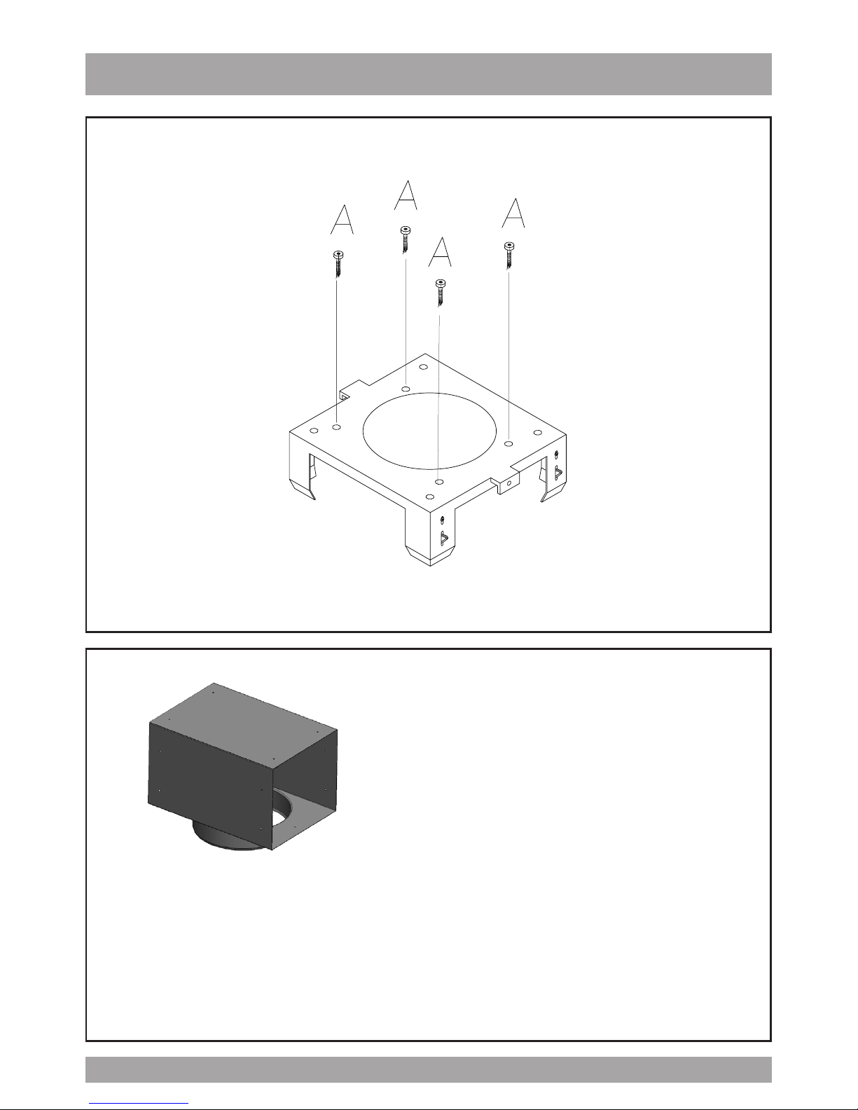
Fixing the Main Support Brackets
Using Bracket “A” as a template mark the
ceiling where the xing screws “A” will be
positioned – remember the correct orien-
tation from above. Attach bracket “A” to
the ceiling permanently. If re-circulating,
attach the deector to Bracket “A” before
xing it to the ceiling – refer schematic on
page 5.
The 2 brackets for the support of the chimney (Part A) is to be installed to Bracket A
with the screws. Fix the structure on the
ceiling by inserting the 2 dowels.
INSTALLATION
Structural Preparation for the Hood
Fan Installation.
The island hood weighs approximately 125
lbs. It is therefore imperative that a substantial structure is prepared in the ceiling
to attach the range hood to. Ideally block
o an area of at least 12”x12” between the
ceiling joists using 2x4’s. Allow for a hole
through the center of this blocking of at
least 6” in diameter through which to pass
the ductwork and electrical cable.
The underside of the hood must not be
closer than 30” from the cook-top and
ideally not higher than 32”above the
cook-top. It is strongly recommended, at
this point, that calculations and measurements be made and all planning and heights be nalized. You will need to t the
appropriate length of ducting to the hood
fan before installing it to the ceiling.
Planning should consist of a test assembly of the power unit and telescoping
structure before attempting to mount
everything to the ceiling. By following
this test assembly you will be able to nalize the correct length of the assembly
before mounting it to the ceiling.
Test assembly should include actually
attaching the following items together
– refer schematic of components and
“Fixing the main support brackets”
below – Brackets A, B, C, power unit and
deector if re-circulating.
This is also a good time to test the electrical
functioning of the hood before it is installed. Before switching on the light or lights,
ensure the tape holding the globes in place
has been removed.
The globes gets extremely hot and will very
quickly burn the tape and discolor the globes irreparably.

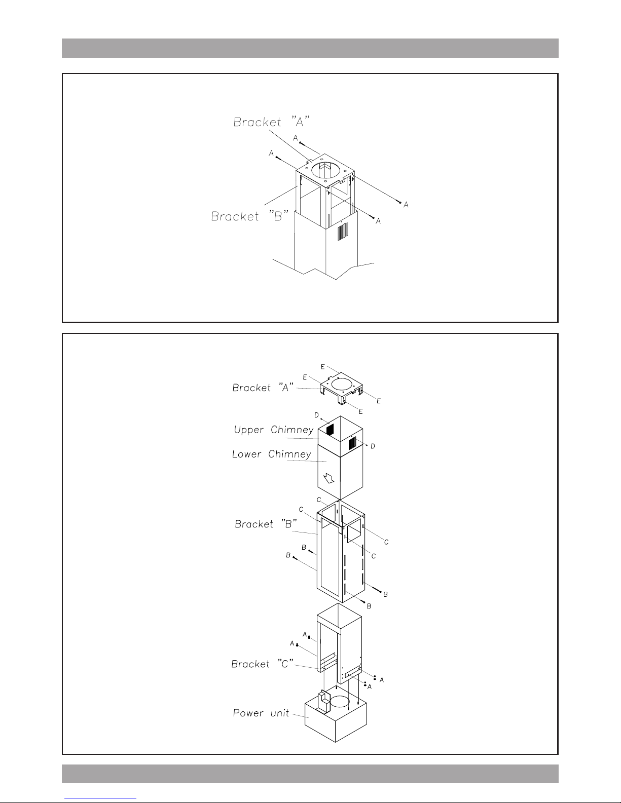
Fix Bracket “C” to the power unit with the
nuts and washers supplied (Items “A” on
the schematic on page 5). Please ensure
that the bracket is installed as shown to
enable full ac-cess to the square plastic
black box and the metal electrical junction box. Slide Bracket “B” over Bracket
“C” (once again ensure full access to the
plastic and electrical boxes is main-tained) and x it in place, at the previously calculated length using the machine screws denoted by items “B” on the
schematic on page 5.
Check that the plastic aps at the exhaust
outlet for the fan move freely and have not
become jammed during shipping or whilst
working with the power unit. Connect an
appropriate length of ducting to the unit.
Do not x the ducting to the outlet with
screws - use DUCT TAPE.
Stand the assembled structure on a clean
soft surface. Ensure the underside of the
hood does not get scratched and slide
the chimneys of the assembled structure
from the top down as per the schematic
on page 5. Ensure that the holes for xing the decorative chimney are correctly orientated with the holes at the top of
bracket A.
Attaching the Range Hood to the Ceiling.
The entire structure that has been preassembled above, must now be hoisted
up to the ceiling. A few things have to
happen at once here: the slots (as discussed below) need to be engaged and
the ductwork must make connection with
the length of ductwork on the structure.
7
This will require two strong people –do
not attempt this step on your own. Bracket “B” has slots, position C per Diagram
“A” (refer to page 5), at the top that will
receive the spring clips located on Bracket
“A” –THIS IS A TEMPORARY HOLD ONLY
–DO NOT RELY SOLELY ON THESE CLIPS
TO HOLD THE HOOD UP – THEY WON’T.
Once “hooked” by the spring clips immediately secure the structure with the machine screws at point “E” on the schematic
on page 5 – this must be done imme-
diately and should not be skipped. Raise the upper chimney to the ceiling and
x it to the bracket “A” with the screws
supplied “D”.
Ensure the entire structure is sturdy - serious injury, death and MAJOR damage
could result should the unit not be well
connected to the frame structure within
the ceiling.
This is of utmost importance – do not go any
further until this has been tested and double
checked – the installer has sole responsibility for the safe installation of this product.
Attaching the Range Hood to the Ceiling.
The entire structure that has been preassembled above, must now be hoisted
up to the ceiling. A few things have to
happen at once here: the slots (as discussed below) need to be engaged and the
ductwork must make connection with the
length of ductwork on the structure.
This will require two strong people –do
not attempt this step on your own. Bracket “B” has slots, position C per Diagram
“A” (refer to page 5), at the top that will
receive the spring clips located on Bracket “A” –THIS IS A TEMPORARY HOLD
ONLY –DO NOT RELY SOLELY ON THESE
CLIPS TO HOLD THE HOOD UP – THEY
WON’T. Once “hooked” by the spring
clips immediately secure the structure
with the machine screws at point “E” on
the schematic on page 5 – this must be
done immediately and should not be
skipped.
Ensure the entire structure is sturdy- serious injury, death and MAJOR damage
could result should the unit not be well
connected to the frame structure within
the ceiling.
This is of utmost importance – do not go
any further until this has been tested and
double checked – the installer has sole
responsibility for the safe installation of
this product.
Once the entire structure has been xed
to the ceiling slide the chimneys on the
assembled structure from the bottom up
as per the schematic on page 5. And x
the chimneys with the screws supplied.
Raise the upper chimney to the ceiling
and x it to the bracket “A” with the
screws supplied “D”.
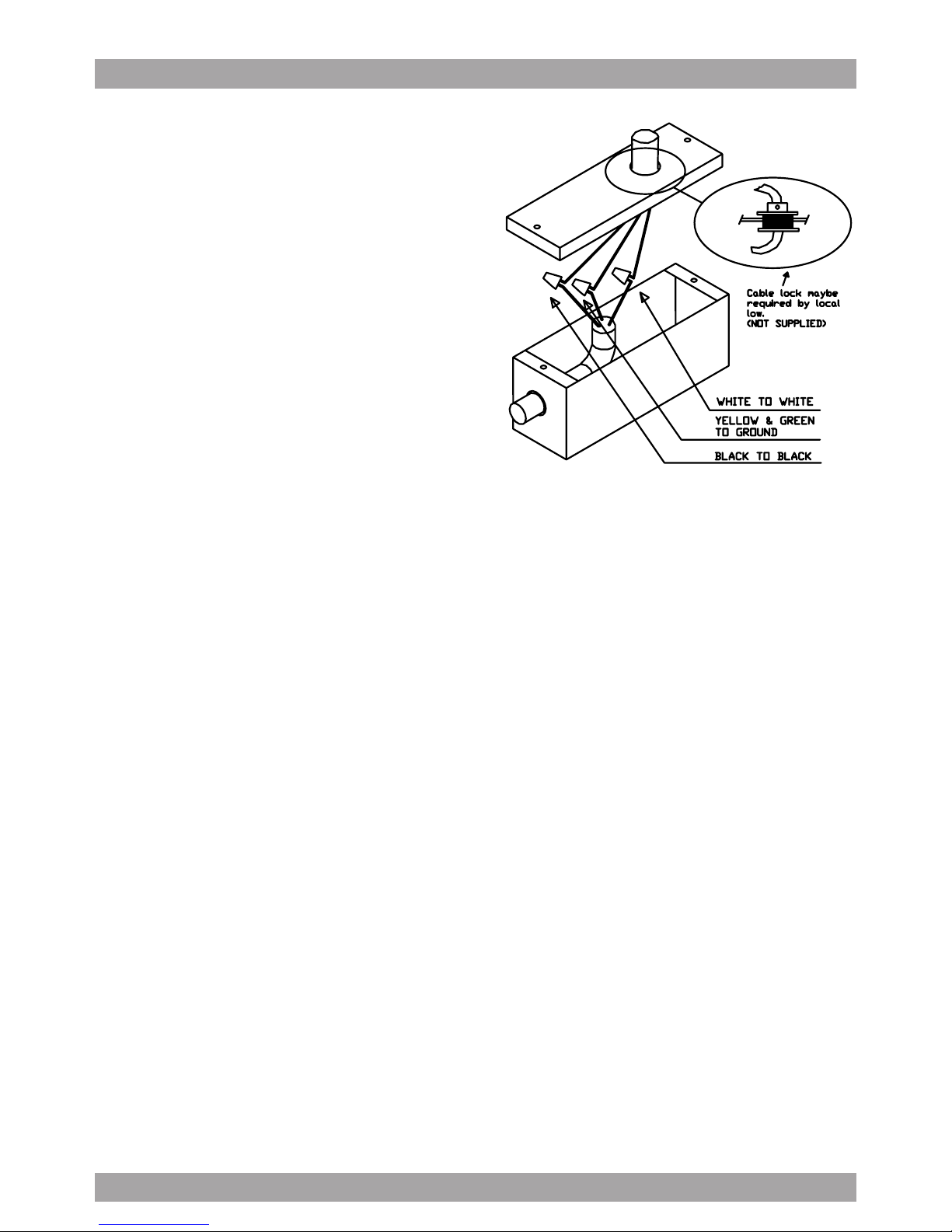
Connecting Electricity and Ducting.
Make sure power is turned o at the
source. Make the electrical connection.
Test the functioning of the hood. Slide
the upper chimney into place and attach
with the machine screws provided to
Bracket “A”.
Re-Circulating Requirements.
Fit the carbon lter after the installation is
complete – these t in behind the aluminum grease lter.
A short length of ductwork must be connected from the exhaust outlet up to the
deector (must be purchased with hood).
The deector, after attaching part B with
screws E connects to the top of Bracket
“A” and forces the air out through the
grills on the side of the chimney section
back into the room. (see diagram C).
8
SCHEMATIC OF MODULAR ISLAND COMPONENTS
9
Diagram c
Bracket
Deector
Part B
Deector attaches to ceiling mount bracket when island hood is installed in re-circulating mode and the air that has passed through the fat and carbon lters is returned
to the room via a short length of 6” round ductwork attached to the power unit and
deector.
10
Diagram b – Securing Bracket “A” to “B”
Please note – this is critically important – do not rely on the spring clips.
Diagram A – Main Assembly
 Loading...