

Foster HR80MF Service Manual
1
By Appointment to
Her Majesty Queen Elizabeth II
Suppliers of Commercial Refrigeration
Foster Refrigerator, King’s Lynn
A Division of ITW Ltd
Foster Refrigerator,
Oldmedow Road,
King’s Lynn,
Norfolk, PE30 4JU
United Kingdom
Original Service Manual
Milk Fridge
HR80MF Models
Bit25 Controller & LCD5S Display
November 2014 Version 1
English
ISO 9001 ISO 14001
1
Contents
Page
Manual Information & Health & Safety Notes 1
Environmental Management Policy 2
Disposal Requirements & Electrical Safety 2
Displays Icons & Switches 3
BIT25 User Functions - Start Up, Set Point, Standby, Key Security & Defrost Function 3-4
BIT25 Controller Connection Drawing & Conguration of Parameters 4-5
BIT25 Controller Default Parameters 6-9
Model Temperature Specic Parameters 10.11
Cleaning Instructions 11
Wiring Diagrams 12
Troubleshooting 13-15
Service Manual Information:
The products and all information in this manual are subject to change without prior notice.
We assume by the information given that the person(s) working on these refrigeration units are
fully trained and skilled in all aspects of their workings. Also that they will use the appropriate safety equipment
and take or meet precautions where required.
The service manual does not cover information on every variation of this unit; neither does it cover the
installation or every possible operating or maintenance instruction for the units.
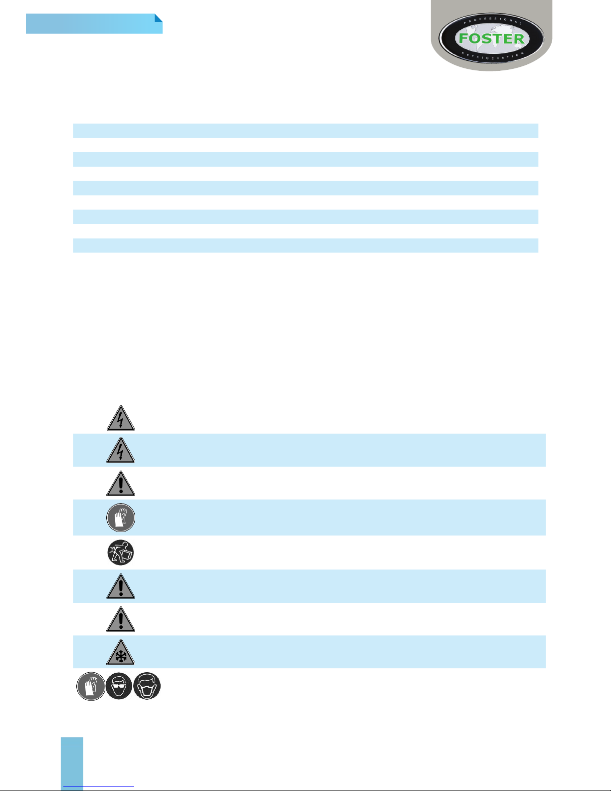
Health & Safety Warnings & Information
Make sure the power supply is turned off before making any electrical repairs.
To minimise shock and re hazards, please do not plug or unplug the unit with wet hands.
During maintenance and cleaning, please unplug the unit where required.
Care must be taken when handling or working on the unit as sharp edges may cause
personal injury, we recommend the wearing of suitable PPE.
Ensure the correct moving and lifting procedures are used when relocating a unit.
Do NOT use abrasive cleaning products, only those that are recommended. Never scour
any parts of the refrigerator. Scouring pads or chemicals may cause damage by scratching
or dulling polished surface nishes.
Failure to keep the condenser clean may cause premature failure of the motor/compressor
which will NOT be covered under warranty policy.
Do NOT touch the cold surfaces in the freezer compartment. Particularly when hands are
damp or wet, skin may adhere to these extremely cold surfaces and cause frostbite.
Please ensure the appropriate use of safety aids or Personnel Protective Equipment (PPE)
are used for you own safety.

2
Environmental Management Policy
Product Support and Installation Contractors.
Foster Refrigerator recognises that its activities, products and services can have an adverse impact upon the
environment.
The organisation is committed to implementing systems and controls to manage, reduce and eliminate its adverse
environmental impacts wherever possible, and has formulated an Environmental Policy outlining our core aims. A copy
of the Environmental Policy is available to all contractors and suppliers upon request.
The organisation is committed to working with suppliers and contractors where their activities have the potential to
impact upon the environment. To achieve the aims stated in the Environmental Policy we require that all suppliers and
contractors operate in compliance with the law and are committed to best practice in environmental management.
Product Support and Installation contractors are required to:
1. Ensure that wherever possible waste is removed from the client’s site, where arrangements are in place all waste
should be returned to Foster Refrigerator’s premises. In certain circumstances waste may be disposed of on the
client’s site; if permission is given, if the client has arrangements in place for the type of waste.
2. If arranging for the disposal of your waste, handle, store and dispose of it in such a way as to prevent its escape
into the environment, harm to human health, and to ensure the compliance with the environmental law. Guidance is
available from the Environment Agency on how to comply with the waste management ‘duty of care’.
3. The following waste must be stored of separately from other wastes, as they are hazardous to the environment:
refrigerants, polyurethane foam, and oils.
4. When arranging for disposal of waste, ensure a waste transfer note or consignment note is completed as
appropriate. Ensure that all waste is correctly described on the waste note and include the appropriate six-digit
code from the European Waste Catalogue. Your waste contractor or Foster can provide further information if
necessary.
5. Ensure that all waste is removed by a registered waste carrier, a carrier in possession of a waste management
licence, or a carrier holding an appropriate exemption. Ensure the person receiving the waste at its ultimate
destination is in receipt of a waste management licence or valid exemption.
6. Handle and store refrigerants in such a way as to prevent their emission to atmosphere, and ensure they are
disposed of safely and in accordance with environmental law.
7. Make arrangements to ensure all staff who handle refrigerants do so at a level of competence consistent with the
City Guilds 2079 Handling Refrigerants qualication or equivalent qualication.
8. Ensure all liquid substances are securely stored to prevent leaks and spill, and are not disposed of into storm
drains, foul drain, or surface water to soil.
Disposal Requirements
If not disposed of properly all refrigerators have components that can be harmful to the
environment.
All old refrigerators must be disposed of by appropriately registered and licensed waste contractors, and in
accordance with national laws and regulations.
General Electrical Safety
Foster Refrigerator recommends that the equipment is electrically connected via a Residual Current Device; such as
a Residual Current Circuit Breaker (RCCB) type socket, or through a Residual Current Circuit Breaker with Overload
Protection (RCBO) supplied circuit.
3
Controller Operation - BIT25
The controller consists of two pieces, the controller (BIT25) and separate display (LCD5S).
The display is positioned inside the cabinet and the controller at the rear.
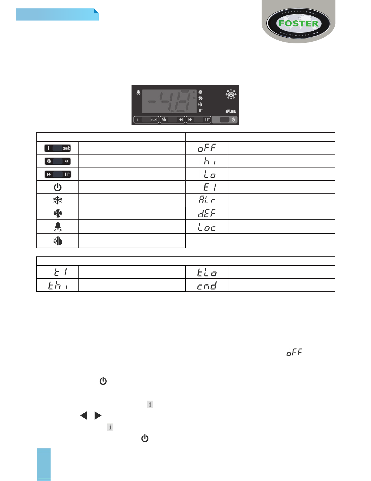
LCD5S Display Icons and Switches
Display Indicators & Buttons Alarms/ Warnings During Normal Operation
Info/ Set Point Button Controller in Standby
Manual Defrost/ Decrease Button Room High Temperature Alarm
Manual Activation/ Increase Button Room Low Temperature Alarm
Exit/ Standby Button Probe T1 Failure (Air)
Thermostat/ Compressor Output Generic Alarm
Fan Output Defrost In Progress
Alarm Warning Keypad Locked
Defrost Output
Information Menu Symbols and Reasons
Instant probe 1 temperature Minimum probe 1 temperature recorded
Maximum probe 1 temperature recorded Compressor working weeks **
** Displayed only if ACC > 0
Start Up and Operation
User Functions
Start Sequence
When the unit is rst connected to the mains the display will automatically light up and show either or the
current ambient temperature.
To start or activate when in standby:
> Press and hold the button for 5 seconds then release.
Access to the menu and information displayed
> Press and immediately release button
> With button or select the data to be displayed
> Press and hold button to display the value
> To exit from the menu, press button or wait for 10 seconds.
4
Set point: Display and modication
> Press button and hold to display the set point.
> By keeping button pressed, use button or to set the desired value (adjustment is within the minimum
SPL and the maximum SPH limit)
> When button is released, the new value is stored.
Standby
When pressing the button for 3 seconds, will allow the controller to be put on a standby or output control to be
resumed (with SB = YES only). When on Standby will be displayed.
Keypad Unlock
Press & release then use to select ‘LOC’. Press and hold to change from ‘YES’ to ‘NO’. Leave for 10
seconds or briey press to resume.
Defrost
Automatic Defrost
The cabinet will defrost automatically on a predened schedule. This setting will also automatically terminate on a
predened schedule.
Manual Defrost. (Freezer Sections only)
To initiate a manual defrost press and hold the defrost button for 2 seconds
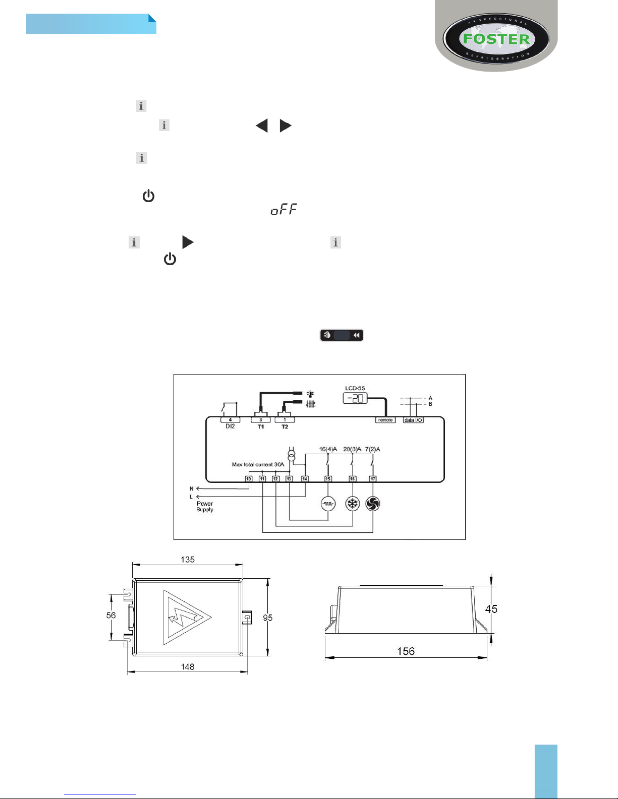
Controller Connection Drawing and Dimensions
(Dimensions in mm)

5
Controller Technical Data
Power Supply Operating Conditions
BIT25 ... E 230Vac±10%, 50/60Hz, 3W -10…+50°C; 15%...80%r.H
Relay Output CE (Reference norms)
Compressor 20(8)A 240Vac
Auxiliary Loads 1 16(4)A 240Vac EN55022 (Class B)
Auxiliary Loads 2 7(2)A 240Vac EN50082-1
Input
NTC 10KΩ@25°C
Measurement Range Measurement Accuracy
-50 / -9.9…19.9 /110°C <0.5°C within the measurement range
Conguration Parameters
> To access to the parameter conguration menu, press + for 5 seconds
> With button or select the parameter to be modied.
> Press button and hold briey to display the value. On releasing the button the controller will then show the
next parameter.
> By keeping button pressed, use button or to set the desired value. On releasing the button the
controller will store the amended value and then show the next parameter.
> To exit from the setup, press button or wait for 30 seconds.
*Dark grey highlight denotes a parameter that may not be visible unless another is set to a specic value.
For example:
OS3 will not show unless DI2 = T3
 Loading...