

Page 1
FX
BLAST CHILLER
ISO 14001
ISO 9001
Page 2

Contents
Environmental Management Policy 1
Disposal Requirements 1
Cabinet description 2
Controller Description
Controller Operation 2 to 3
Alarms & Warnings 4
Parameter Setting and Adjustment 4 to 6
Technical Specification 6
Spare Parts List 7
Wiring Diagrams 8 to 15
Environmental Management Policy for Service Manuals and Duets.
Product Support and Installation Contractors
Foster Refrigerator recognises that its activities, products and services can have an adverse impact upon the
environment.
The organisation is committed to implementing systems and controls to manage, redu ce and eliminate its adverse
environmental impacts wherever possible, and has formulated an Environmental Policy outlining our core aims. A copy
of the Environmental Policy is available to all contractors and suppliers upon request.
The organisation is committed to working with suppliers and contractors where their activities have the potential to
impact upon the environment. To achieve the aims stated in the Environmental Policy we require that all suppliers and
contractors operate in compliance with the law and are committed to best practice in environmental management.
Product Support and Installation contractors are required to:
1. Ensure that wherever possible waste is removed from the client’s site, where arrangements are in place all waste
should be returned to Foster Refrigerator’s premises. In certain circumstances waste may be disposed of on the
clients site; if permission is given, if the client has arrangements in place for the type of waste.
2. If arranging for the disposal of your waste, handle, store and dispose of it in such a way as to prevent its escape
into the environment, harm to human health, and to ensure the compliance with the environmental law. Guidance
is available from the Environment Agency on how to comply with the waste management ‘duty of care’.
3. The following waste must be stored of separately from other wastes, as they are hazardous to the environment:
refrigerants, polyurethane foam, oils.
4. When arranging for disposal of waste, ensure a waste transfer note or consi gnment note is completed as
appropriate. Ensure that all waste is correctly described on the waste note and include the appropriate six-digit
code from the European Waste Catalogue. Your waste contractor or Foster can provide further information if
necessary.
5. Ensure that all waste is removed by a registered waste carrier, a carrier in possession of a waste management
licence, or a carrier holding an appropriate exemption. Ensure the person receiving the waste at its ultimate
destination is in receipt of a waste management licence or valid exemption.
6. Handle and store refrigerants in such a way as to prevent their emission to atmosphere, and ensu re they are
disposed of safely and in accordance with environmental law.
7. Make arrangements to ensure all staff who handle refrigerants do so at a level of competence consistent with the
City Guilds 2078 Handling Refrigerants qualification or equivalent qualification.
8. Ensure all liquid substances are securely stored to prevent leaks and spill, and are not disposed of to storm
drains, foul drain, surface water to soil.
DISPOSAL REQUIREMENTS
If not disposed of properly all refrigerators have components that can be harmful to the environment. All old
refrigerators must be disposed of by appropriately registered and licensed waste contractors, and in accordance with
national laws and regulations.
1
Page 3
Cabinet Description
Controls located in the unit cover.
All of the cabinet range incorporates bottom mounted refrigeration systems with the evaporator located on the back
wall.
The refrigerant used is R404a.
Door operated fan switches stop the fans when the door is opened.
FXBC10, FXBC 20, FXBC30 all 230/1/50Hz 13amp
FXBC40 230/1/50Hz 16amp.
The internal base is flat with drain connection in the centre to an external drain via a flexible hose. (Vaporisation tray
with electric heater available as an option)
FXBC 10: Blast Chiller, 10kg capacity with three GN1/1 shelves.
FXBC 20: Blast Chiller, 20kg capacity with five GN1/1 shelves.
FXBC 30: Blast Chiller, 30kg capacity with eight GN1/1 shelves.
FXBC 40: Blast Chiller, 40kg capacity with twelve GN1/1 shelves.
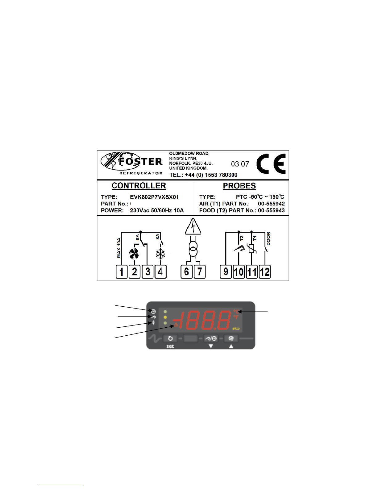
Controller Description
The controller is mains voltage 230-50/60-1
00 - 555941
Set-Temperature Chilling LED
Timed Chilling LED
Degree Celsius LED
Storage LED
Alarm LED
The device has the following operational states:
• ‘ON’ the controller is switched on and an operating cycle is running.
• ‘stand-by’ the controller is switched on but no operating cycle is running.
• ‘off’ the controller is switched off
If there is a power failure during a timed blast chilling operation, when the power is restored, chilling will continue from
the point at which the interruption occurred.
If there is a power failure during a set temperature blast chilling operation, when power is restored, chilling will start
from the beginning.
If there is a power failure during the storage operation, when power is restored the storage operation will be continue.
2
Page 4

Controller operation
Prior to starting a chill operation ensure the controller is in the ‘stand-by’ mode.
Timed chill operation
To place the controller in ‘stand–by’ press for 2 seconds, whilst in stand-by the cabinet internal air
temperature will be displayed intermittently.
Press ‘PoS’ will be displayed and the Timed Chilling LED will be flashing.
Press to display the chilling time, set to 90 minutes as standard, if no change to the time is required press
to start the programme.
If changes to the chill time are required press ‘PoS’ will be displayed and the Timed Chilling LED
will be flashing, press to display the chilling time followed by to decrease the time or to
increase.
During chilling the display will show the time remaining with the Timed Chilling LED on.
Once the chilling time is completed the controller switches to the storage mode with the display showing ‘End’ press
any button to mute the alarm, press to cancel the message.
Whilst the cabinet is in the storage mode the internal cabinet temperature will be displayed and the Timed Chilling LED
and Storage LED will be illuminated.
To stop the programme press for 2 se conds
NOTE:
If changes are made to the time settings on completion of the programme the time will revert back to the default setting
of 90 minutes.
Temperature chill operation
Place the controller in ‘stand–by’ pressing for 2 seconds.
Ensure that the food probe is inserted into the product prior to commencing the temperature chill programme.
Press ‘PoS’ will be displayed and the Timed Chilling LED may be flashing, if it is Press
again to display Set-Temperature Chilling LED flashing.
Press the display will show the product end temperature, +3ºC as standard, if no change to the temperature
is required press to start the programme.
If changes to the chill termination temperature are required press ‘PoS’ will be displayed and the SetTemperature Chilling LED will be flashing, press to display the chilling temperature followed by
to decrease the temperature or to increase.
Once the product temperature has been achieved the controller switches to storage mode with the display showing
‘End’ press any button to mute the alarm, press to cancel the message.
Whilst the cabinet is in the storage mode the internal cabinet temperature will be displayed and the SetTemperature Chilling LED and Storage LED will be illuminated.
To stop the programme press for 2 se conds
NOTE:
If changes are made to the temperature settings on completion of the programme the temperature will revert back to
the default setting of +3ºC.
3
Page 5
Defrost
Defrost will be initiated automatically in the hold mode at pre-set intervals.
To initiate a manual defrost during the hold mode press for 5 seconds, defrost will start with
d
being displayed.
Alarm and Warnings
d
AL Low Temperature Alarm
AH High Temperature Alarm
Defrost in operation
PR1 Air Probe fault
PR2 Food Probe Fault
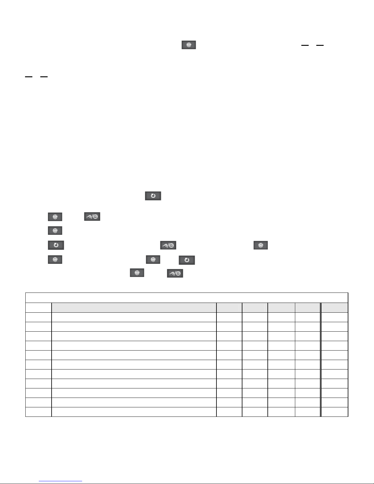
Parameter Setting and Adjustment
Setting the configuration parameters
The parameters are arranged on two levels
Access to the First Level
To access the parameters the controller must be in the stand-by mode.
To place the controller in ‘stand–by’ press for 2 seconds, whilst in stand-by the cabinet internal air
temperature will be displayed intermittently.
Press and for 4 seconds the display will show ‘PA’.
Press ‘r0’ will be displayed.
Press to display the value followed by to decrease the value or to increase the value.
Press to return to the followed by to move to the next parameter.
On completion of the changes press plus to exit or wait 60 secon ds
First Level Configuration Parameters
Mnem. Definition Min. Max Default Dim. FXBC
r0
r1
r2
r3
r4
r5
r6
r7
r8
r9
rA
4
Parameter r7, r8, r9 and Ra hysteresis 0.1 15.0 2.0 °K 2.0
Timed positive blast chilling duration 1 600 90 min. 90
Timed negative blast chilling duration 1 600 240 min. 240
Positive blast chill end point temperature (food probe) -99.0 99.0 3.0 °C 3.0
Negative blast chill end point temperature (food probe) -99.0 99.0 -18.0 °C -18.0
Set temperature positive blast chilling duration 1 600 90 min. 90
Set temperature negative blast chilling duration 1 600 240 min. 240
Positive blast chilling setpoint (air temp.) -99.0 99.0 0.0 °C 0.0
Negative blast chilling setpoint (air temp.) -99.0 99.0 -40.0 °C -25.0
Post positive blast chilling storage setpoint
Post negative blast chilling storage setpoint -99.0 99.0 -20.0 °C -20.0
-99.0 99.0 2.0 °C 2.0
Page 6
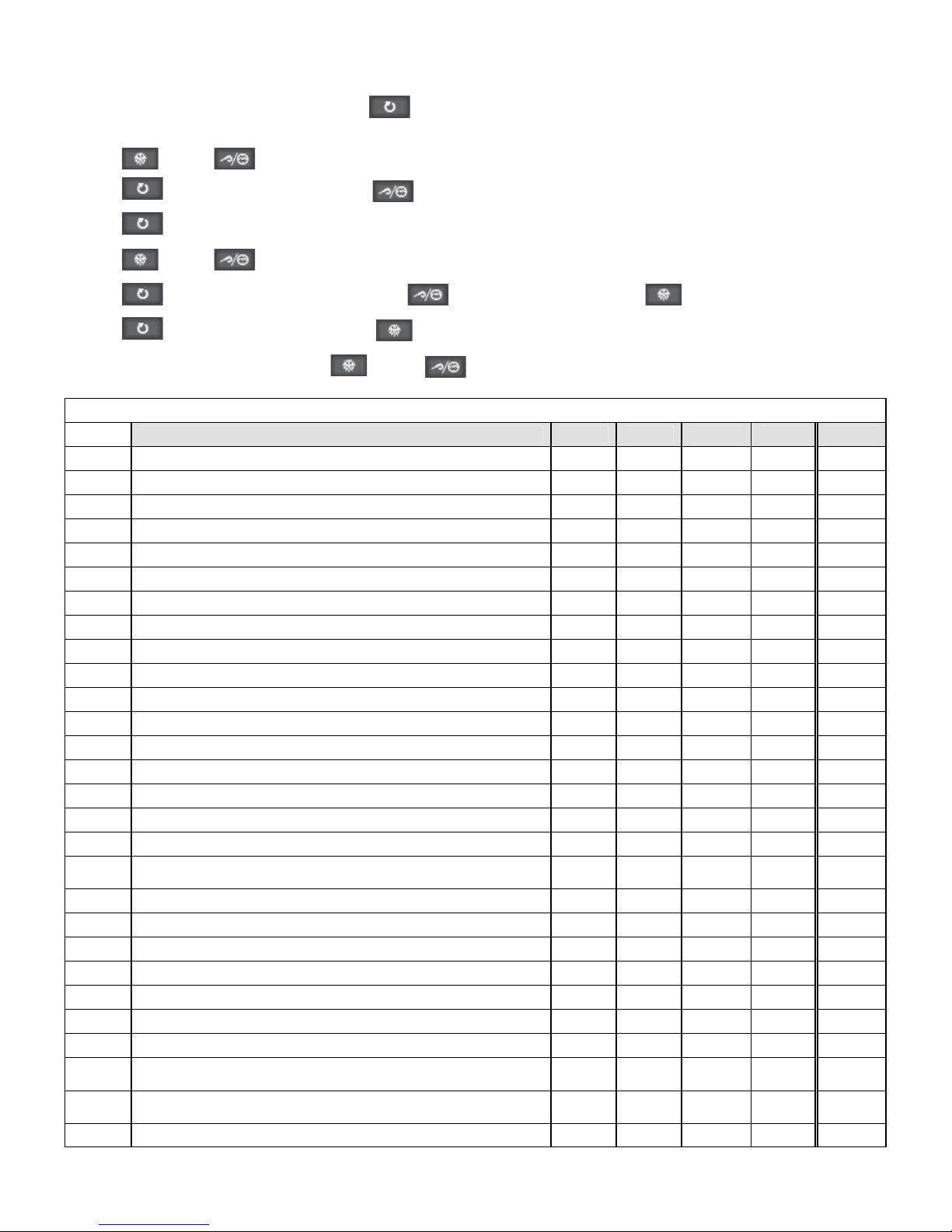
Access to the second level
To access the parameters the controller must be in the stand-by mode.
To place the controller in ‘stand–by’ press for 2 seconds, whilst in stand-by the cabinet internal air
temperature will be displayed intermittently.
Press and for 4 seconds the display will show ‘PA’.
Press ‘0’ will be displayed, press to change the setting to ‘-19’
Press ‘PA’ will be displayed.
Press and for 4 seconds the display will show ‘CA1’ the first parameter in the second level.
Press to display the value followed by to decrease the value or to increase the value.
Press to return to the followed by to move to the next parameter.
On completion of the changes press plus to exit or wait 60 secon ds
Second Level Configuration Parameters
Mnem. Definition Min. Max Default Dim. Default
CA1
CA2
P0
P1
P2
P3
r0
r1
r2
r3
r4
r5
r6
r7
r8
r9
rA
rb
rc
rd
C0
C1
C2
C3
C4
C5
C6
C11
Air probe offset -25 25 0 °K 0
Food probe offset -25 25 0 °K 0
Probe type (0 = PTC, 1 = NTC) 0 1 0 flag 0
Decimal point active (0 = No, 1 = Yes) 0 1 1 flag 0
o
Temperature unit (0 =
Food probe activation (0 = No, 1 = Yes) 0 1 1 flag 1
Differential of parameters r7, r8, r9 and rA 0.1 15.0 2.0 °K 2.0
Timed positive blast chilling duration 1 600 90 min. 90
Timed negative blast chilling duration 1 600 240 min. 240
Positive blast chill end point temperature (food probe) -99.0 99.0 3.0 °C 3.0
Negative blast chill end point temperature (food probe) -99.0 99.0 -18.0 °C -18.0
Set temperature positive blast chilling duration 1 600 90 min. 90
Set temperature negative blast chilling duration 1 600 240 min. 240
Positive blast chilling setpoint (air temp.) -99.0 99.0 0.0 °C 0.0
Negative blast chilling setpoint (air temp.) -99.0 99.0 -40.0 °C -25.0
Post positive blast chilling storage setpoint
Post negative blast chilling storage setpoint -99.0 99.0 -20.0 °C -20.0
Negative blast chilling and storage enabling 0 (NO)
Test for food probe insertion differential (0 = no test) 0.0 99.0 5 °K 5
Duration of probe insertion test 1 99 60 sec. 60
Compressor start delay 0 240 0 min. 0
Compressor interval between starts 0 240 5 min. 5
Minimum compressor shut down time 0 240 3 min. 3
Minimum compressor run time 0 240 0 sec. 0
Compressor shut down with air probe error in hold (if 'C11' = 0) 0 240 10 min. 10
Compressor shut down with air probe error in positive chill cycle
(if 'C11' = 0)
Compressor shut down with air probe error in negative chill cycle
(if 'C11' = 0)
Food probe operation with air probe failure 0 1 0 flag 0
C, 1 = oF) 0 1 0 flag 0
-99.0 99.0 2.0 °C 2.0
1
(YES)
0 240 10 min. 10
0 240 20 min. 20
1 flag 0
5
Page 7

d0
d3
d7
A1
A2
A4
A5
A6
A7
A8
A9
AA
F0
F2
F8
i0
i1
i2
i3
i7
u0
LA
Lb
LP
E9
Defrost interval (0 = defrost not active) 0 99 8 hrs. 8
Defrost duration (0 = defrost not active) 0 99 30 min. 20
Drip time duration 0 15 2 min. 2
Minimum temp alarm 0.0 99.0 10 °C 5
Minimum temp alarm type (depends on 'r9' & 'rA' [or 'r9-A1' and
'rA-A1'])
Maximum temp alarm 0.0 99.0 10 °C 5
Maximum temp alarm type (depends on 'r9' & 'rA' [or 'r9+A4' and
'rA+A4'])
Storage temp alarm delay (from start) 0 240 15 min. 15
Temperature alarm delay 0 240 15 min. 15
Drip time end high temperature alarm delay 0 240 15 min. 15
Maximum high temperature alarm delay (only if i0 = 0 or 1) 0 240 15 min. 15
Blast chill cycle completion alarm duration 0 240 5 sec. 20
Evaporator fan operation during chilling (0 = off; 1 = on; 2 = with
compressor)
Evaporator fan operation during hold (0 = off; 1 = on; 2 = with
compressor)
Evaporator fan start up delay following defrost
Digital input operation (0 = Output a; 1 = output b; 2 = comp.
protection)
Digital input contact type (0 = NO; 1 = NC; 2 = no input)
Digital input alarm delay (only if i0 = 0 or 1) [-1 = no alarm sound]
Digital input effect duration (only if i0 = 0 or 1) [-1 = until input
disabled]
Compressor protection deactivation delay (only if 'i0' = 2)
Relay K2 operation (0 = defrosting; 1 = evaporator fan)
Device address
Baud rate (0 = 2.4k; 1 = 4.8k; 2 = 9.6k; 3 = 19.2k)
Parity (0 = none; 1 = odd; 2 = even)
Not used
0 (NO
Alarm)
0 (NO
Alarm)
0 2 2 flag 1
0 2 1 flag 1
0 99 0 min. 2
0 2 1 flag 0
0 2 2 flag 1
-1 120 30 min. 30
-1 120 15 min. -1
0 120 0 min. 0
0 1 1 flag 1
1 247 1 flag 1
0 3 2 flag 2
0 2 2 flag 2
0 1 1 exp. 1
1 1 flag 1
1 1 flag 1
Technical Data
FXBC10 FXBC 20 FXBC 30 FXBC 40
Nominal Chilling Capacity 10Kg 20Kg 30Kg 40Kg
Duty @ -15°C 826w 1182w 1909w
Fans 1 1 2 2
Defrost Load (amps) N/A N/A N/A N/A
Evaporating Temperature -15°C -15°C -15°C -15°C
Refrigerant Control TEV TEV TEV TEV
Refrigerant R404a R404a R404a R404a
Refrigerant Quantity 1300g 1500g 2700g 2700g
Electrical Supply 230/1/50 – 13amp 230/1/50 – 13amp 230/1/50 – 13amp 230/1/50 – 16amp
Power Consumption
Watts 738
Amps 3.44
Watts 1089
Amps 5.1
Watts 1994
Amps 9.05
Power absorbed W 730 1120 1990
Total Heat Rejection 1564w 2271w 3903w
6
Page 8

Spare Parts List
ITEM DESCRIPTION PART NUMBER MODEL
Controller EVK802 00-555941 All Models
Air Probe ECSND0112A 00-555942 All Models
Food Probe ECSNDX0008 00-555943 All Models
Compressor MX16TB 00-555674 FXBC10
Compressor CAJ9513Z 00-554334 FXBC20
Compressor MS26TB 00-555682 FXBC30
Compressor MS34TB 00-555677 FXBC40
Condenser Fan Motor Grid Mount 16W 15470027 FXBC10, FXBC20,
Condenser Fan Motor 00-555413 FXBC30, FXBC40
Condenser Coil Coil 012504 00-878508-01 FXBC10
Condenser Coil Coil 012654 00-554998 FXBC20
Condenser Coil Coil 013521 00-555405 FXBC30, FXBC 40
Drier DML 033S 00-555388 All Models
Solenoid Valve EVR6 15451215 FXBC30, FXBC 40
Evaporator Coil Coil 013584 00-555412 FXBC10
Evaporator Coil Coil 013524 00-555410 FXBC20
Evaporator Coil Coil 013475 00-555408 FXBC30, FXBC40
Evaporator Fan Motor 00-555374 FXBC10
Evaporator Fan Motor 00-555375
Expansion Valve Body TES2-N 68Z3417/68 15450385 All Models
Orifice 00 68-20900/68-207 15451102 FXBC10, FXBC20,
Orifice 02 68-2092/68-2072 15451104 FXBC30, FXBC40
Expansion Valve Solder Adaptor 15450910 All Models
High Pressure Switch (28 BAR) 00-555386 All Models
Low Pressure Switch (4PSI) 00-555387 FXBC30, FXBC 40
Door Switch Circular (Reed Type) 00-555829 All Models
Door Switch Magnet Circular 00-555828 All Models
Door Gasket Magnet 597.5x385 01-232996-01 FXBC10
Door Gasket Magnet 597.5x551.5 01-232909-01 FXBC20
Door Gasket Magnet 597.5x1151.5 01-232852-01 FXBC30
Door Gasket Magnet 597.5x1151.5 01-232852-01 FXBC40
FXBC20, FXBC30,
FXBC40
7
Page 9

FXBC 10 Wiring Diagram
8
Page 10

FXBC 10R Wiring Diagram
9
Page 11

FXBC 20R Wiring Diagram
10
Page 12

FXBC 20R Wiring Diagram
11
Page 13

FXBC 30 Wiring Diagram
12
Page 14

13
FXBC 30R Wiring Diagram
Page 15

FXBC 40 Wiring Diagram
14
Page 16

FXBC 40R Wiring Diagram
15
Page 17

16
Page 18

17
Page 19

18
Page 20

Foster European Operations
rance
F
oster Refrigerator France SA
F
el: (33) 01 34 30 22 22. Fax: (33) 01 30 37 68 74.
T
E
mail: commercial@fosterfrance.com
Germany
F
oster Refrigerator Gmbh,
T
el: (49) 7819907840. Fax (49)7819907844.
E
mail: info@foster-gmbh.de
Foster Refrigerator
O
ldmedow Road
K
ings Lynn
N
orfolk
P
E30 4JU
T
el: 01553 691122
F
ax: 01553 691447
W
ebsite: www.fosterrefrigerator.co.uk
Email: sales@foster-uk.com
a Division of ‘ITW (UK) Ltd’
XBC/ SM 06/07
F
19
 Loading...