

Page 1
Standalone Linear Li-ion Battery Charger with Thermal Regulation
FEATURES
z Programmable charge current up to 800mA
z No MOSFET, sense resistor or blocking diode
required
z Complete linear charger in thin SOT package for
single cell lithium–ion batteries
z Constant-current/constant-voltage operation with
thermal regulation to maximize charge rate
without risk of overheating
z Charges single cell Li-ion batteries directly from
USB port
z Preset 4.2V charge voltage with ±1% accuracy
z Charge current monitor output for gas gauging
z Automatic recharge
z Charge status output pin
z C/10 charge termination
z 25uA supply current in shutdown
z 2.9V trickle charge threshold
z Soft-start limits inrush current
z Space saving ThinSOT23-5L package
APPLICATIONS
z Cellular phones, PDAs
z Bluetooth applications
z Charging docks and Cradles
z MP3 players
PIN CONFIGURATION
(Top View)
PIN DESCRIPTION
Pin Number
1 CHRG Open-drain charge status output
2 GND Ground
3 BAT Charge current output
4 Vcc Positive input supply voltage
5 PROG Charge current program, Charge current monitor and shutdown pin
Pin Name
TYPICAL APPLICATIONS CIRCUITS
600mA single cell Li-ion charger
FSP4054
GENERAL DESCRIPTION
The FSP4054 is a complete
constant-current/constant-voltage linear charger for
cell lithium-ion batteries. Its Thin SOT23-5L package
and low external component count make the FSP4054
ideally suited for portable applications. Furthermore,
the FSP4054 is specifically designed to work within
USB power specifications.
No external sense resistor is needed, and no blocking
diode is required due to the internal MOSFET
architecture. Thermal feedback regulators the charge
current to limit the die temperature during high power
operation or high ambient temperature. The charge
voltage is fixed at 4.2V, and the charge current can be
programmed externally with a single resistor. The
FSP4054 automatically terminates the charge cycle
when the charge current drops to 1/10
programmed value after the final float voltage is
reached.
When the input supply (wall adapter or USB supply) is
removed, the FSP4054 automatically enters a low
current state, dropping the battery drain current to less
than 2uA. The FSP4054 can be put into shutdown
mode, reducing the supply current to 25uA.
Other features include charge current monitor,
undervoltage lockout, automatic recharge and a status
pin to indicate charge termination and the presence of
an input voltage.
1
2
3
5
4
Pin Function
th
the
1/15
2007-7-3
Page 2
Standalone Linear Li-ion Battery Charger with Thermal Regulation
BLOCK DIAGRAM
PIN FUNCTION
CHRG: When the battery is charging, the CHRG pin is pulled low by an internal N-channel MOSFET. When the
charge cycle is completed, a weak pull-down of approximately 20uA is connected to the CHRG pin, including an “AC
present” condition. When the FSP4054 detects an undervoltage lockout condition, CHRG is forced high impedance.
GND: Ground.
BAT: Provides charge current to the battery and regulators the final voltage to 4.2V. An internal precision resistor
divider from this pin sets the float voltage which is disconnected in shutdown mode.
Vcc: Provides power to the charger. Vcc can range from 4.25V to 6.5V and should be bypassed with at least a 1uF
capacitor. When Vcc drops to within 30mV of the BAT pin voltage, the FSP4054 enters shutdown mode, dropping
I
to less than 2uA.
BAT
PROG: The charge current is programmed by connected a 1% resistor, R
constant-current mode, this pin servos to 1V. In all modes, the voltage on this pin can be used to measure the
charge current using the following formula:
The PROG pin can also be used to shut down the charger. Disconnecting the program resistor from ground allows a
3uA current to pull the PROG pin high. When it reaches the 1.21V shutdown threshold voltage, the charger enters
shutdown mode, charging stops and the input supply current drops to 25uA. This pin is also clamped to
approximately 2.4V. Driving this pin to voltages beyond the clamp voltage will draw current as high as 1.5mmA.
Reconnected R
to ground will return the charger to normal operation.
PROG
FSP4054
, to ground. When charging in
PROG
2/15
2007-7-3
Page 3
Standalone Linear Li-ion Battery Charger with Thermal Regulation
OPERATION
The FSP4054 is a single cell lithium-ion battery charger using a constant-current/constant-voltage algorithm. It can
deliver up to 800mA of charge current (using a good thermal PCB layout) with a final voltage accuracy of ±1%. The
FSP4054 includes an internal P-channel power MOSFET and thermal regulation circuitry. No blocking diode or
external current sense resistor is required; thus, the basic charger circuit requires only two external components.
Furthermore, the FSP4054 is capable of operating from a USB power source.
Normal charge cycle
A charge cycle begins when the voltage at the Vcc pin rises above the UVLO threshold level and a 1% program
resistor is connected from the PROG pin to ground or when a battery is connected to the charger output. If the BAT
pin is less than 2.9V, the charger enters trickle charge mode. In this mode, the FSP4054 supplies approximately
1/10 the programmed charge current to bring the battery voltage up to a safe level for full current charging.
When the BAT pin voltage rises above 2.9V, the charger enters constant-current mode, where the programmed
charge current is supplied to the battery. When the BAT pin approaches the final float voltage (4.2V), the FSP4054
enters constant-voltage mode and the charge current begins to decrease. When the charge current drops to 1/10 of
the programmed value, the charge cycle ends.
Programmed charge current
The charge current is programmed using a single resistor from the PROG pin to ground. The battery charge current
is 1000 times the current out of the PROG pin. The program resistor and the current are calculated using the
following equations:
The charge current out of the BAT pin can be determined at any time by monitoring the PROG pin voltage using the
following equation:
Charge termination
A charge cycle is terminated when the charge current falls to 1/10
is reached. This condition is detected by using an internal, filtered comparator to monitor the PROG pin. When the
PROG pin voltage falls below 100mV for longer than t
and the FSP4054 enters standby mode, where the input supply current drops to 200uA. (Note: C/10 termination is
disabled in trickle charging and thermal limiting modes)
When charging, transient loads on the BAT pin can cause the PROG pin to fall below 100mV for short periods of
time before the DC charge current has dropped to 1/10
termination comparator ensures that transient loads of this nature do not result in premature charge cycle
termination. Once the average charge current drops below 1/10
the charge cycle and ceases to provide any current through the BAT pin. In this state, all loads on the BAT pin must
be supplied by the battery.
The FSP4054 constantly monitor the BAT pin voltage in standby mode. If this voltage drops below the 4.05V
recharge threshold, another charge cycle begins and current is once again supplied to the battery. To manually
restart a charge cycle when in standby mode, the input voltage must be removed and reapplied, or the charger must
be shut down and restarted using the PROG pin. The figure 1shows the state diagram of a typical charge cycle.
Charge status indicator
The charge status output has three different states: strong pull-down(10mA), weak pull-down (20uA) and high
impedance. The strong pull-down state indicates that the FSP4054 is in a charge cycle. Once the charge cycle has
terminated, the pin state is determined by undervoltage lockout conditions. A weal pull-down indicates that Vcc
meets the UVLO conditions and the FSP4054 is ready to charge. High impedance indicates that the FSP4054 is in
undervoltage lockout mode: either VCC is less than 100mV above the BAT pin voltage or insufficient voltage is
applied to the VCC pin. A microprocessor can be used to distinguish between these three states—this method is
discussed in the Applications Information section.
Thermal limiting
An internal thermal feedback loop reduces the programmed charge current if the die temperature attempts to rise
above a preset value of approximately 120°C. This feature protects the FSP4054 from excessive temperature and
allows the user to push the limits of the power handling capability of a given circuit board without risk of damaging
the FSP4054. The charge current can be set according to typical (not worst-case) ambient temperature with the
3/15
FSP4054
th
the programmed value after the final float voltage
, charging is terminated. The charge current is latched off
TERM
th
the programmed value. The 1ms filter time on the
th
the programmed value, the FSP4054 terminates
2007-7-3
Page 4
Standalone Linear Li-ion Battery Charger with Thermal Regulation
assurance that the charger will automatically reduce the current in worst-case conditions. ThinSOT power
considerations are discussed further in the Applications Information section.
Undervoltage Lockout UVLO)
An internal undervoltage lockout circuit monitors the input voltage and keeps the charger in shutdown mode until
VCC rises above the undervoltage lockout threshold. The UVLO circuit has a built-in hysteresis of 200mV.
Furthermore, to protect against reverse current in the power MOSFET, the UVLO circuit keeps the charger in
shutdown mode if VCC falls to within 30mV of the battery voltage. If the UVLO comparator is tripped, the charger will
not come out of shutdown mode until VCC rises 100mV above the battery voltage.
Manual shutdown
At any point in the charge cycle, the FSP4054 can be put into shutdown mode by removing R
PROG pin. This reduces the battery drain current to less than 2mA and the supply current to less than 50mA. A new
charge cycle can be initiated by reconnecting the program resistor.
In manual shutdown, the CHRG pin is in a weak pull-down state as long as VCC is high enough to exceed the UVLO
conditions. The CHRG pin is in a high impedance state if the FSP4054 is in undervoltage lockout mode: either VCC
is within 100mV of the BAT pin voltage or insufficient voltage is applied to the VCC pin.
Automatic recharge
Once the charge cycle is terminated, the FSP4054 continuously monitors the voltage on the BAT pin using a
comparator with a 2ms filter time (t
(which corresponds to approximately 80% to 90% battery capacity). This ensures that the battery is kept at or near a
fully charged condition and eliminates the need for periodic charge cycle initiations. CHRG output enters a strong
pulldown state during recharge cycles.
RECHARGE
Figure 1:the state diagram of a typical charge cycle
). A charge cycle restarts when the battery voltage falls below 4.05V
FSP4054
thus floating the
PROG
4/15
2007-7-3
Page 5
Standalone Linear Li-ion Battery Charger with Thermal Regulation
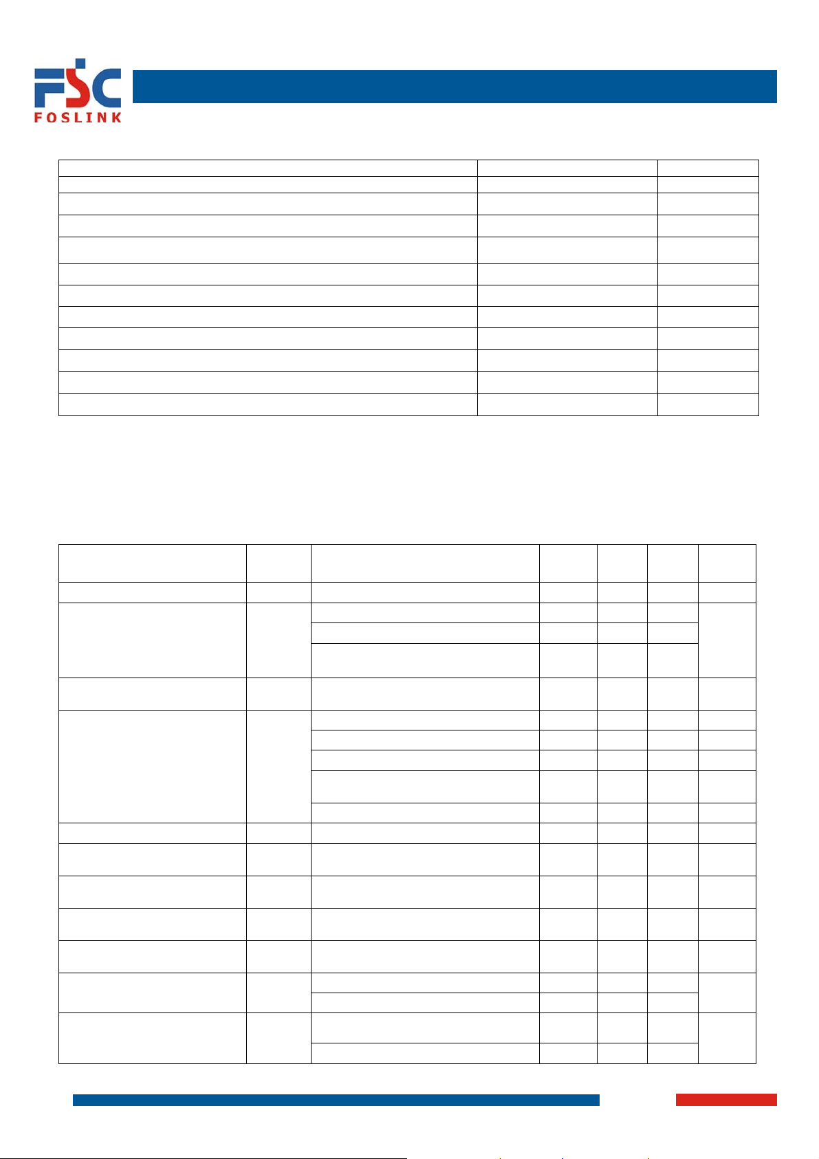
ABSOLUTE MAXIMUM RATINGS(NOTE 1)
Parameter Rating Unit
Input Supply Voltage -0.3 to 10 V
PROG -0.3 to Vcc + 0.3
BAT -0.3 to 7 V
CHRG
BAT short-circuit duration continuous
BAT pin current 800 mA
PROG pin current 800 uA
Operating temperature(Note 2) -40 to 85 °C
Maximum Junction Temperature 125 °C
Storage Temperature -65 to 150 °C
Lead Temperature (Soldering, 10 sec) 300 °C
Note 1: Absolute Maximum Ratings are those values beyond which the life of a device may be impaired.
Note 2: The FSP4054 is guaranteed to meet performance specifications from 0°C ~ 70°C. Specifications over the
-40°C ~85°C operating temperature range are assured by design, characterization and correlation with
statistical process controls.
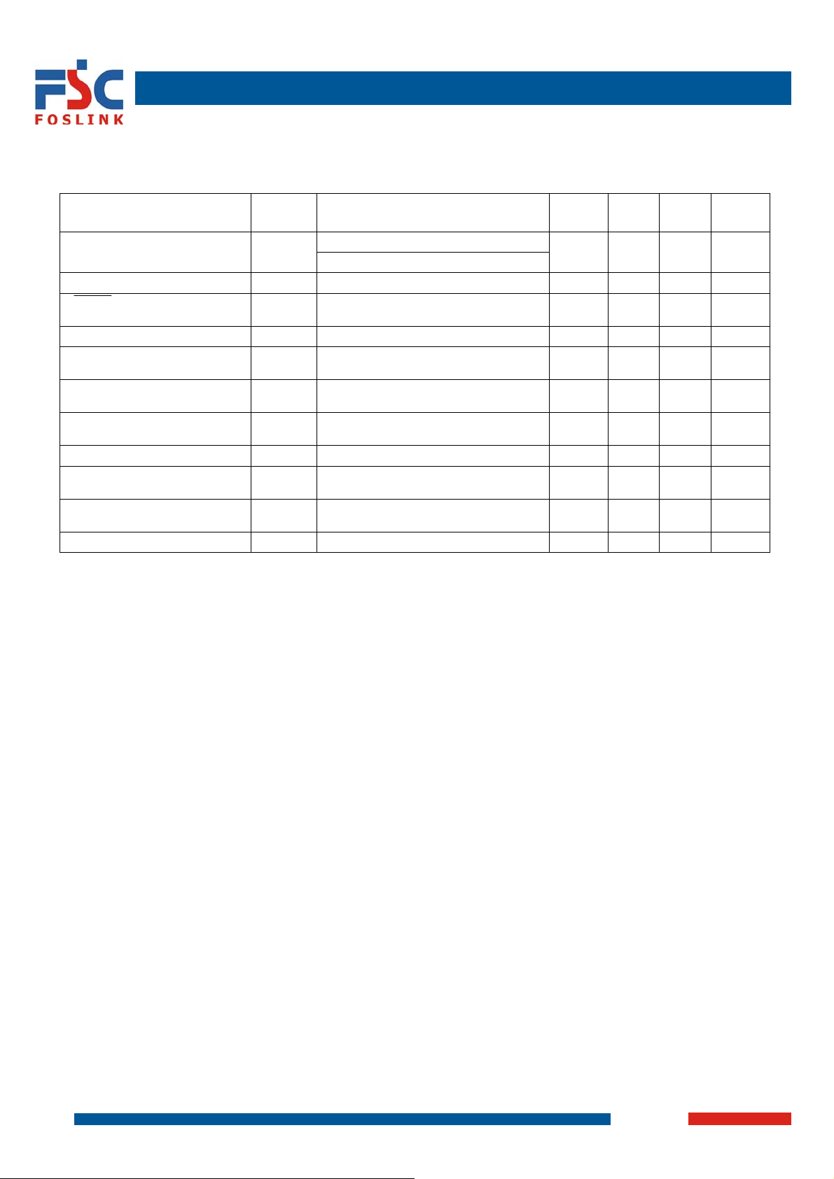
ELECTRICAL CHARACTERISTICS
The * denotes specifications which apply over the full operating temperature range, otherwise specifications are at
TA=25°C. Vcc=5V, unless otherwise noted.
PARAMETER
Input Voltage Vcc * 4.25 6.5 V
Input supply current Icc
Regulated output (Float)
voltage
BAT pin current I
Trickle charge current I
Trickle charge threshold
voltage
Trickle charge hystersis
voltage
Vcc undervoltage lockout
threshold
Vcc undervoltage lockout
hystersis
Manual shutdown threshold
voltage
SYMBO
L
TEST CONDITIONS MIN TYP MAX UNIT
*Charge mode(Note3) R
*Standby mode(Charge terminated) 200 500
*Shutdown mode(R
connected, V
V
FLOAT
0°C<TA<85°C, I
*R
PROG
*R
*V
BAT
BAT
Shutdown mode(R
V
TRIKL
V
R
TRIKL
V
R
TRHYS
V
*From Vcc low to high 3.7 3.8 3.92 V
UV
* 150 200 300 mV
V
UVHYS
V
MSD
*V
FSP4054
V
-0.3 to 10 V
=10k 300 2000
PROG
not
PROG
CC<VBAT
, or VCC<VUV)
=40mA
BAT
=10k, current mode 93 100 107 mA
=2k, current mode 465 500 535 mA
PROG
=4.2V, Standby mode 0 -2.5 -6 uA
not
PROG
connected,
=0V, Sleep mode ±1 ±2 uA
CC
BAT<VTRIKL, RPROG
=10k, V
PROG
BAT
=10k 60 80 110 mV
PROG
=2k
Rising 2.8 2.9 3.0 V
*PROG pin rising 1.15 1.21 1.30
*PROG pin falling 0.9 1.0 1.0
25 50
4.158 4.2 4.242 V
±1 ±2 uA
20 45 70 mA
uA
V
5/15
VCC – V
lockout threshold
BAT
voltage
V
ASD
Vcc from low to high 70 100 140
mV
Vcc from high to low 5 30 50
2007-7-3
Page 6
Standalone Linear Li-ion Battery Charger with Thermal Regulation
ELECTRICAL CHARACTERISTICS (CONTINUED)
The * denotes specifications which apply over the full operating temperature range, otherwise specifications are at
TA=25°C. Vcc=5V, unless otherwise noted.
)
SYMBO
L
I
TERM
*R
PROG
I
V
CHRG
TEST CONDITIONS MIN TYP MAX UNIT
*R
PROG
I
∆V
V
RECHRG
T
120
LIM
R
600 mΩ
ON
PARAMETER
C/10 termination current
threshold
PROG pin voltage V
CHRG pin weak pull-down
current
CHRG pin output low voltage
Recharge battery threshold
voltage
Junction temperature in
constant temperature mode
Power FET “ON” resistance
(between Vcc and V
BAT
Soft-start time tss =0 to I
Recharge comparator filter
time
Termination comparator filter
time
PROG pin pull-up current I
t
RECHARGE
T
VI
I
TERM
3 uA
PROG
BAT
Note 3: Supply current includes PROG pin current (approximately 100uA) but does not include any current delivered
to the battery through the BAT pin (approximately 100mA)
Note 4: I
is expressed as a function of measured full charge current with indicated PROG resistor
TERM
6/15
FSP4054
=10k (Note 4)
PROG
PROG
=2k
*R
=10k, current mode 0.93 1.0 1.07 V
=5V 8 20 35 uA
CHRG
=5mA 0.35 0.6 V
CHRG
-V
FLOAT
=1000V/R
BAT
high to low 0.75 2 4.5 ms
BAT
falling below I
100 150 200 mV
RECHRG
100 us
PROG
/10 400 1000 2500 us
CHRG
0.085 0.10 0.115 mA/mA
2007-7-3
°C
Page 7
Standalone Linear Li-ion Battery Charger with Thermal Regulation
APPLICATION INFORMATION
Stability Considerations
The constant-voltage mode feedback loop is stable without an output capacitor provided a battery is connected to
the charger output. With no battery present, an output capacitor is recommended to reduce ripple voltage. When
using high value, low ESR ceramic capacitors, it is recommended to add a 1W resistor in series with the capacitor.
No series resistor is needed if tantalum capacitors are used. In constant-current mode, the PROG pin is in the
feedback loop, not the battery. The constant-current mode stability is affected by the impedance at the PROG pin.
With no additional capacitance on the PROG pin, the charger is stable with program resistor values as high as 20k.
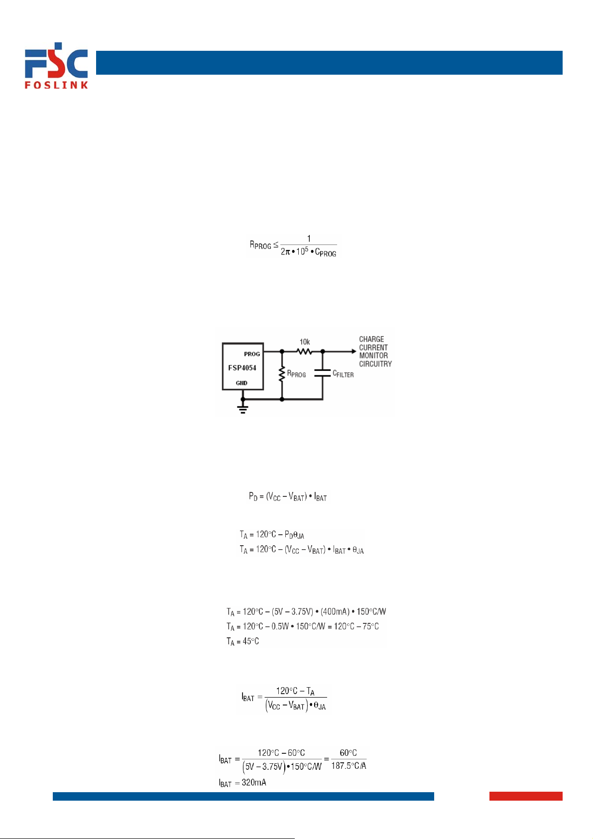
However, additional capacitance on this node reduces the maximum allowed program resistor. The pole frequency
at the PROG pin should be kept above 100kHz. Therefore, if the PROG pin is loaded with a capacitance, C
following equation can be used to calculate the maximum resistance value for R
Average, rather than instantaneous, charge current may be of interest to the user. For example, if a switching power
supply operating in low current mode is connected in parallel with the battery, the average current being pulled out of
the BAT pin is typically of more interest than the instantaneous current pulses. In such a case, a simple RC filter can
be used on the PROG pin to measure the average battery current as shown in Figure 2. A 10k resistor has been
added between the PROG pin and the filter capacitor to ensure stability.
Figure 2: Isolating capacitive load on PROG pin and filtering
Power Dissipation
The conditions that cause the FSP4054 to reduce charge current through thermal feedback can be approximated by
considering the power dissipated in the IC. Nearly all of this power dissipation is generated by the internal MOSFET
-this is calculated to be approximately:
where PD is the power dissipated, VCC is the input supply voltage, V
current. The approximate ambient temperature at which the thermal feedback begins to protect the IC is:
Example: An FSP4054 operating from a 5V USB supply is programmed to supply 400mA full-scale current to a
discharged Li-Ion battery with a voltage of 3.75V. Assuming θ
the FSP4054 will begin to reduce the charge current is approximately:
The FSP4054 can be used above 45°C ambient, but the charge current will be reduced from 400mA. The
approximate current at a given ambient temperature can be approximated by:
Using the previous example with an ambient temperature of 60°C, the charge current will be reduced to
approximately:
7/15
FSP4054
:
PROG
is the battery voltage and I
BAT
is 150°C/W, the ambient temperature at which
JA
2007-7-3
is the charge
BAT
PROG
, the
Page 8
Standalone Linear Li-ion Battery Charger with Thermal Regulation
Moreover, when thermal feedback reduces the charge current, the voltage at the PROG pin is also reduced
proportionally as discussed in the Operation section. It is important to remember that FSP4054 applications do not
need to be designed for worst-case thermal conditions since the IC will automatically reduce power dissipation when
the junction temperature reaches approximately 120°C.
Increasing Thermal Regulation Current
Reducing the voltage drop across the internal MOSFET can significantly decrease the power dissipation in the IC.
This has the effect of increasing the current delivered to the battery during thermal regulation. One method is by
dissipating some of the power through an external component, such as a resistor or diode.
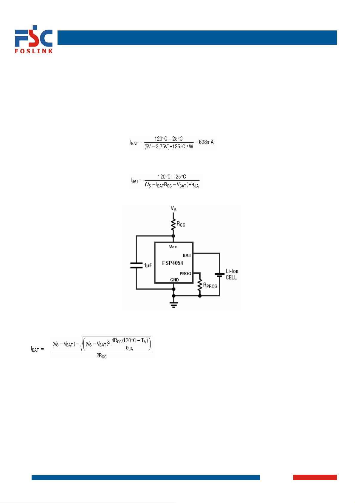
Example: An FSP4054 operating from a 5V wall adapter is programmed to supply 800mA full-scale current to a
discharged Li-Ion battery with a voltage of 3.75V. Assuming θ
ambient temperature of 25°C is:
By dropping voltage across a resistor in series with a 5V wall adapter (shown in Figure 3), the on-chip power
dissipation can be decreased, thus increasing the thermally regulated charge current
Figure 3: A circuit to maximize thermal mode charge current
Solving for I
Using RCC = 0.25W, VS = 5V, V
using the quadratic formula.
BAT
= 3.75V, TA = 25°C and θJA = 125°C/W we can calculate the thermally
BAT
regulated charge current to be:
= 708.4mA
I
BAT
While this application delivers more energy to the battery and reduces charge time in thermal mode, it may actually
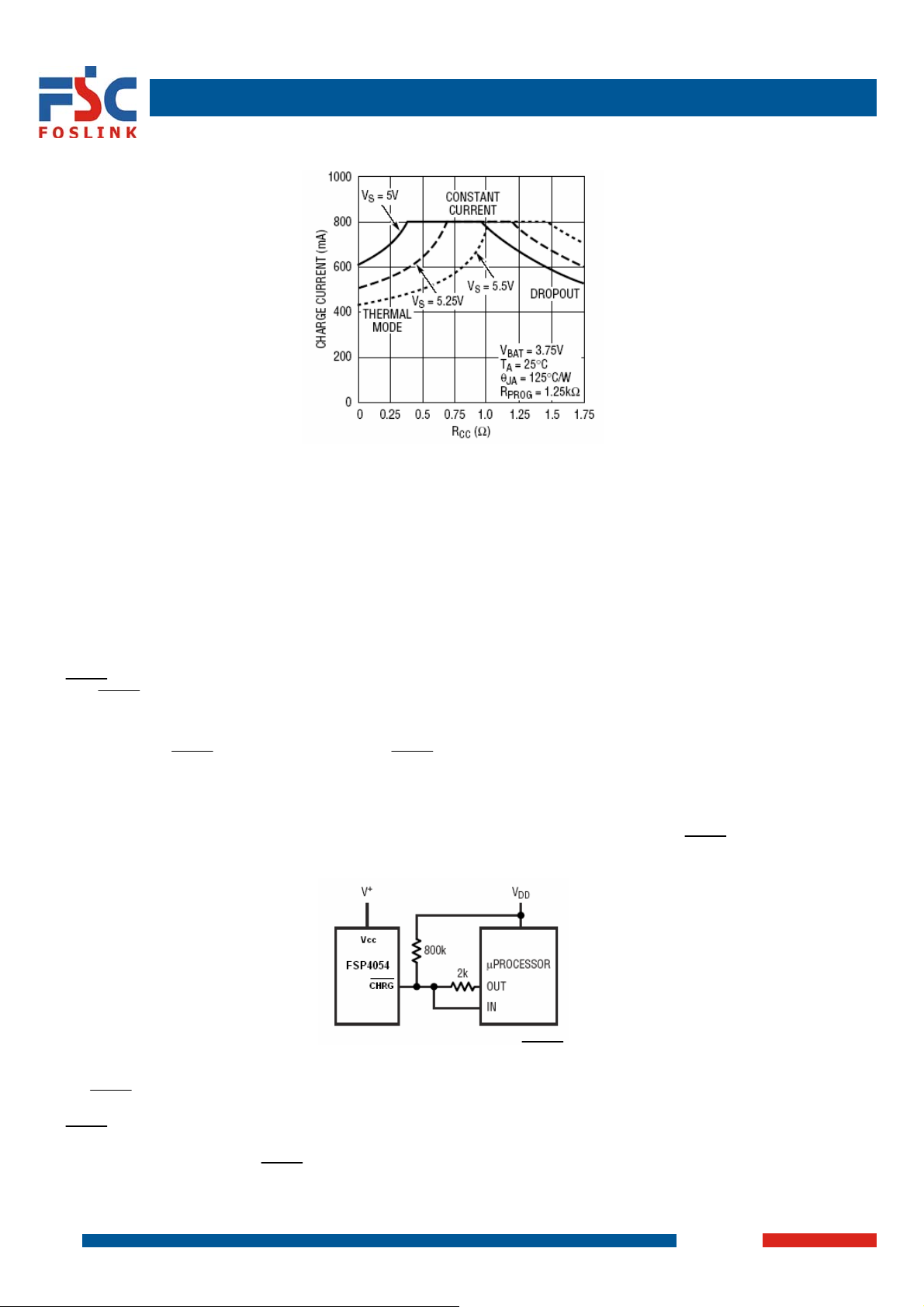
lengthen charge time in voltage mode if VCC becomes low enough to put the FSP4054 into dropout. Figure 4 shows
how this circuit can result in dropout as R
This technique works best when R
values are minimized to keep component size small and avoid dropout.
CC
becomes large.
CC
Remember to choose a resistor with adequate power handling capability.
8/15
FSP4054
is 125°C/W, the approximate charge current at an
JA
2007-7-3
Page 9
Standalone Linear Li-ion Battery Charger with Thermal Regulation
Figure 4: Charge current vs RCC
VCC Bypass Capacitor
Many types of capacitors can be used for input bypassing, however, caution must be exercised when using
multilayer ceramic capacitors. Because of the self-resonant and high Q characteristics of some types of ceramic
capacitors, high voltage transients can be generated under some start-up conditions, such as connecting the
charger input to a live power source. Adding a 1.5W resistor in series with an X5R ceramic capacitor will minimize
start-up voltage transients. For more information, refer to Application Note 88.
Charge Current Soft-Start
The FSP4054 includes a soft-start circuit to minimize the inrush current at the start of a charge cycle. When a
charge
cycle is initiated, the charge current ramps from zero to the full-scale current over a period of approximately 100ms.
This has the effect of minimizing the transient current load on the power supply during start-up.
CHRG Status Output Pin
The CHRG pin can provide an indication that the input voltage is greater than the undervoltage lockout threshold
level. A weak pull-down current of approximately 20mA indicates that sufficient voltage is applied to VCC to begin
charging. When a discharged battery is connected to the charger, the constant current portion of the charge cycle
begins and the CHRG pin pulls to ground. The CHRG pin can sink up to 10mA to drive an LED that indicates that a
charge cycle is in progress.
When the battery is nearing full charge, the charger enters the constant-voltage portion of the charge cycle and the
charge current begins to drop. When the charge current drops below 1/10 of the programmed current, the charge
cycle ends and the strong pull-down is replaced by the 20mA pull-down, indicating that the charge cycle has ended.
If the input voltage is removed or drops below the undervoltage lockout threshold, the CHRG pin becomes high
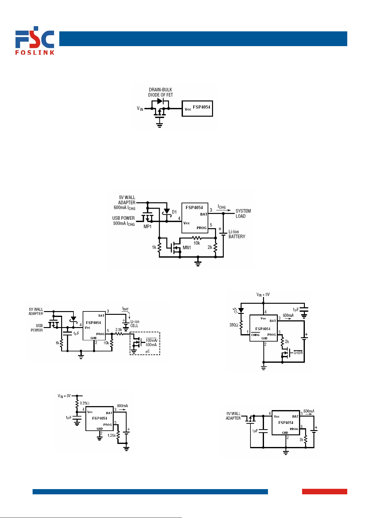
impedance. Figure 5 shows that by using two different value pull-up resistors, a microprocessor can detect all three
states from this pin.
Figure 5: Microprocessor to determine CHRG state
To detect when the FSP4054 is in charge mode, force the digital output pin (OUT) high and measure the voltage at
the CHRG pin. The N-channel MOSFET will pull the pin voltage low even with the 2k pull-up resistor. Once the
charge cycle terminates, the N-channel MOSFET is turned off and a 20mA current source is connected to the
CHRG pin. The IN pin will then be pulled high by the 2k pull-up resistor. To determine if there is a weak pull-down
current, the OUT pin should be forced to a high impedance state. The weak current source will pull the IN pin low
through the 800k resistor; if CHRG is high impedance, the IN pin will be pulled high, indicating that the part is in a
UVLO state.
Reverse Polarity Input Voltage Protection
FSP4054
9/15
2007-7-3
Page 10
Standalone Linear Li-ion Battery Charger with Thermal Regulation
In some applications, protection from reverse polarity voltage on VCC is desired. If the supply voltage is high
enough, a series blocking diode can be used. In other cases, where the voltage drop must be kept low a Pchannel
MOSFET can be used (as shown in Figure 6).
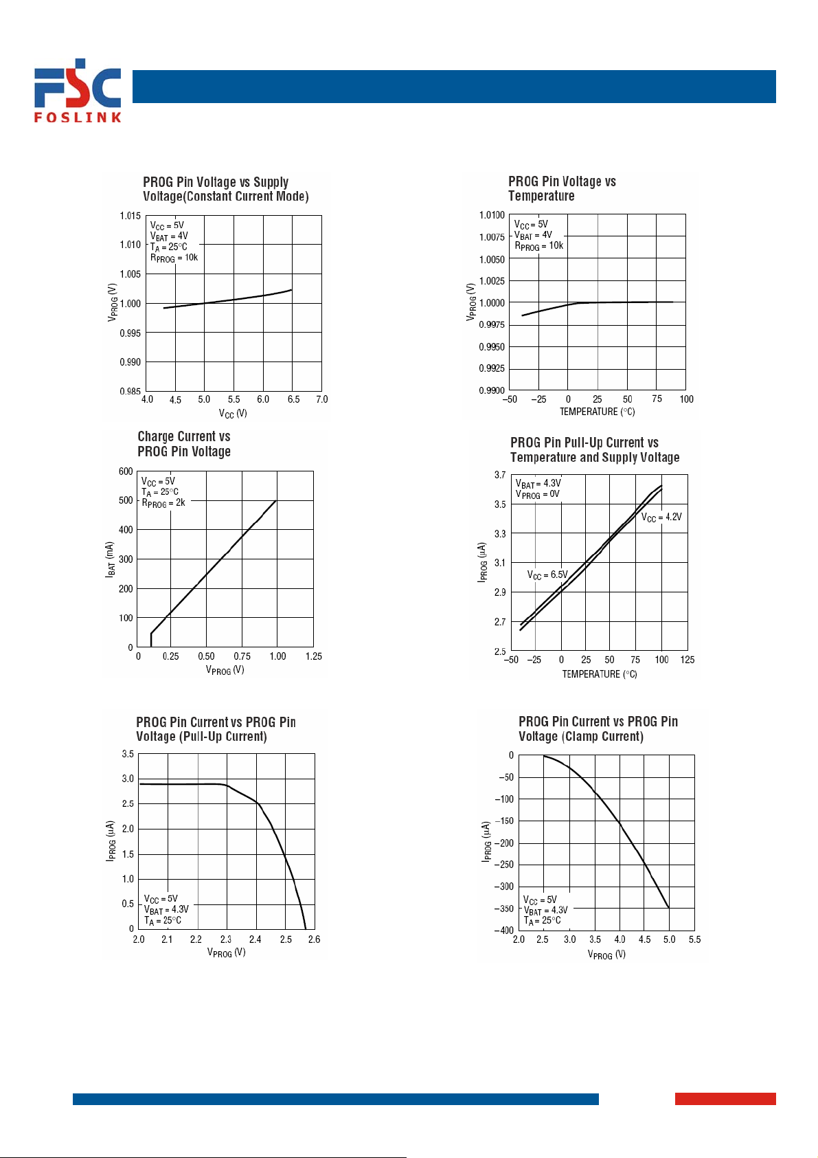
Figure 6: Low loss input reverse polarity protection
USB and Wall Adapter Power
The FSP4054 allows charging from both a wall adapter and a USB port. Figure 7 shows an example of how to
combine wall adapter and USB power inputs. A P-channel MOSFET, MP1, is used to prevent back conducting into
the USB port when a wall adapter is present and a Schottky diode, D1, is used to prevent USB power loss through
the 1k pull-down resistor.
Typically a wall adapter can supply more current than the 500mA-limited USB port. Therefore, an N-channel
MOSFET, MN1, and an extra 10k program resistor are used to increase the charge current to 600mA when the wall
adapter is present.
Figure 7: Combining wall adapter and USB power
TYPICAL APPLICATIONS
USB/wall adapter power Li-ion charger Full featured single cell Li-ion charger
800mA Li-ion charger with external power dissipation Basic Li-ion charger with reverse polarity input protection
10/15
FSP4054
2007-7-3
Page 11
Standalone Linear Li-ion Battery Charger with Thermal Regulation
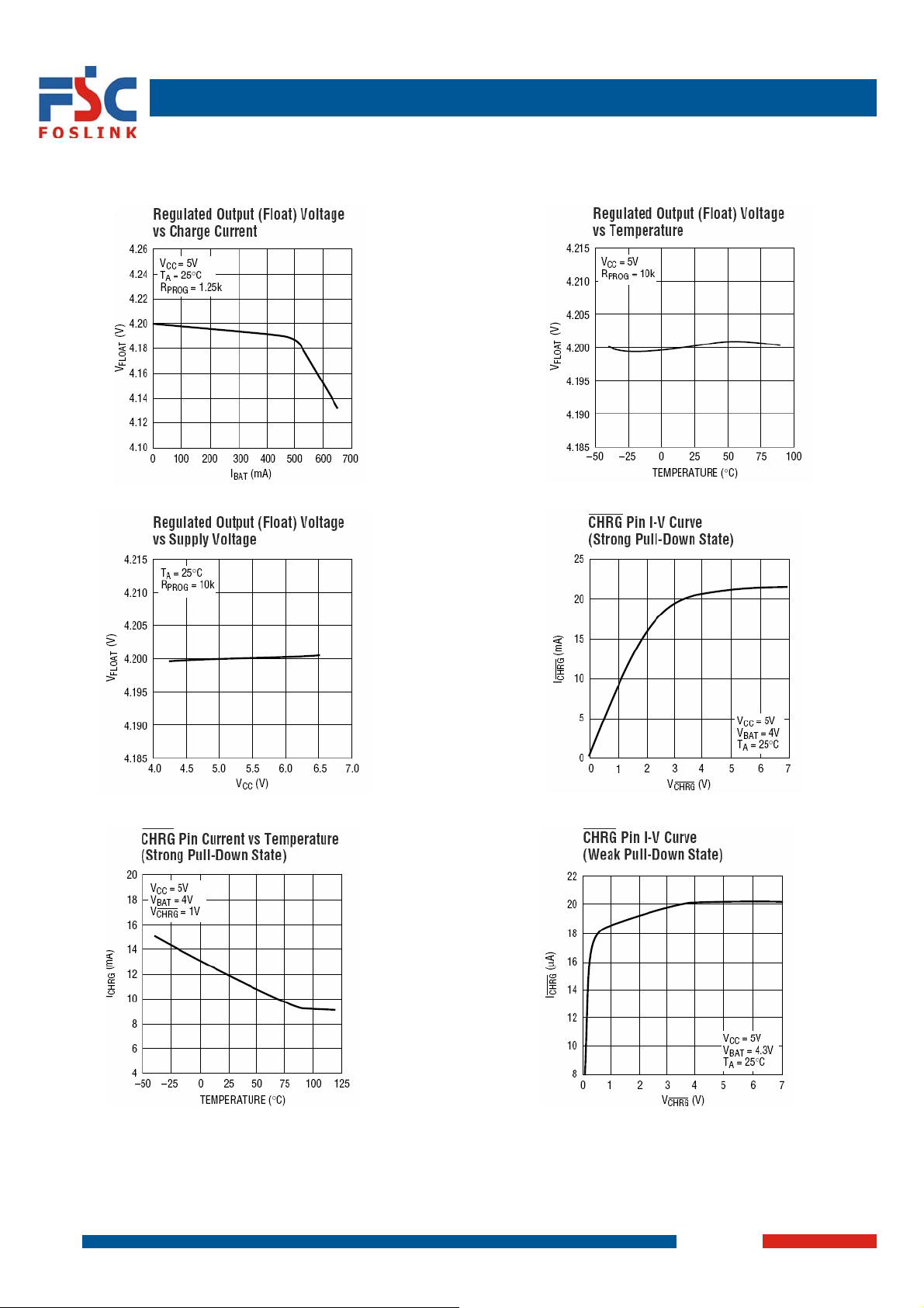
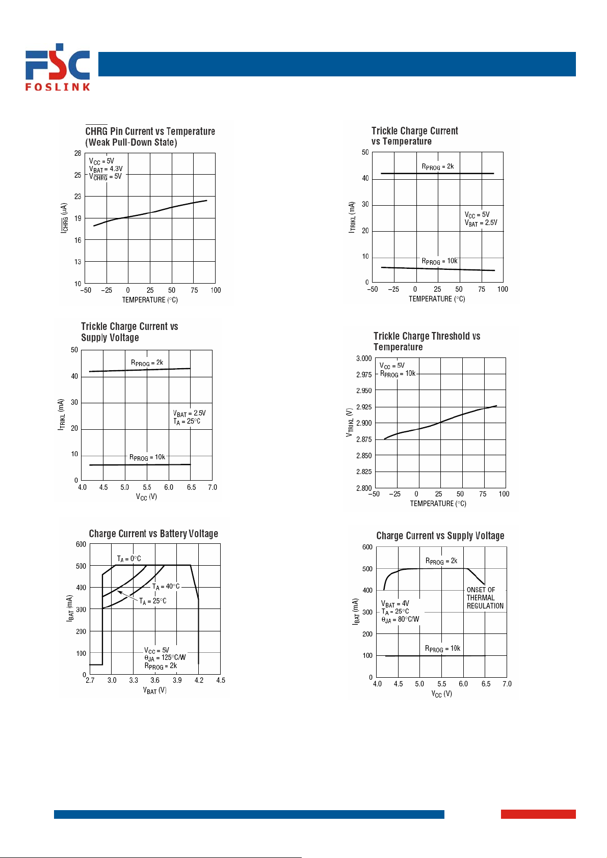
TYPICAL PERFORMANCE CHARACTERISTICS
11/15
FSP4054
2007-7-3
Page 12
Standalone Linear Li-ion Battery Charger with Thermal Regulation
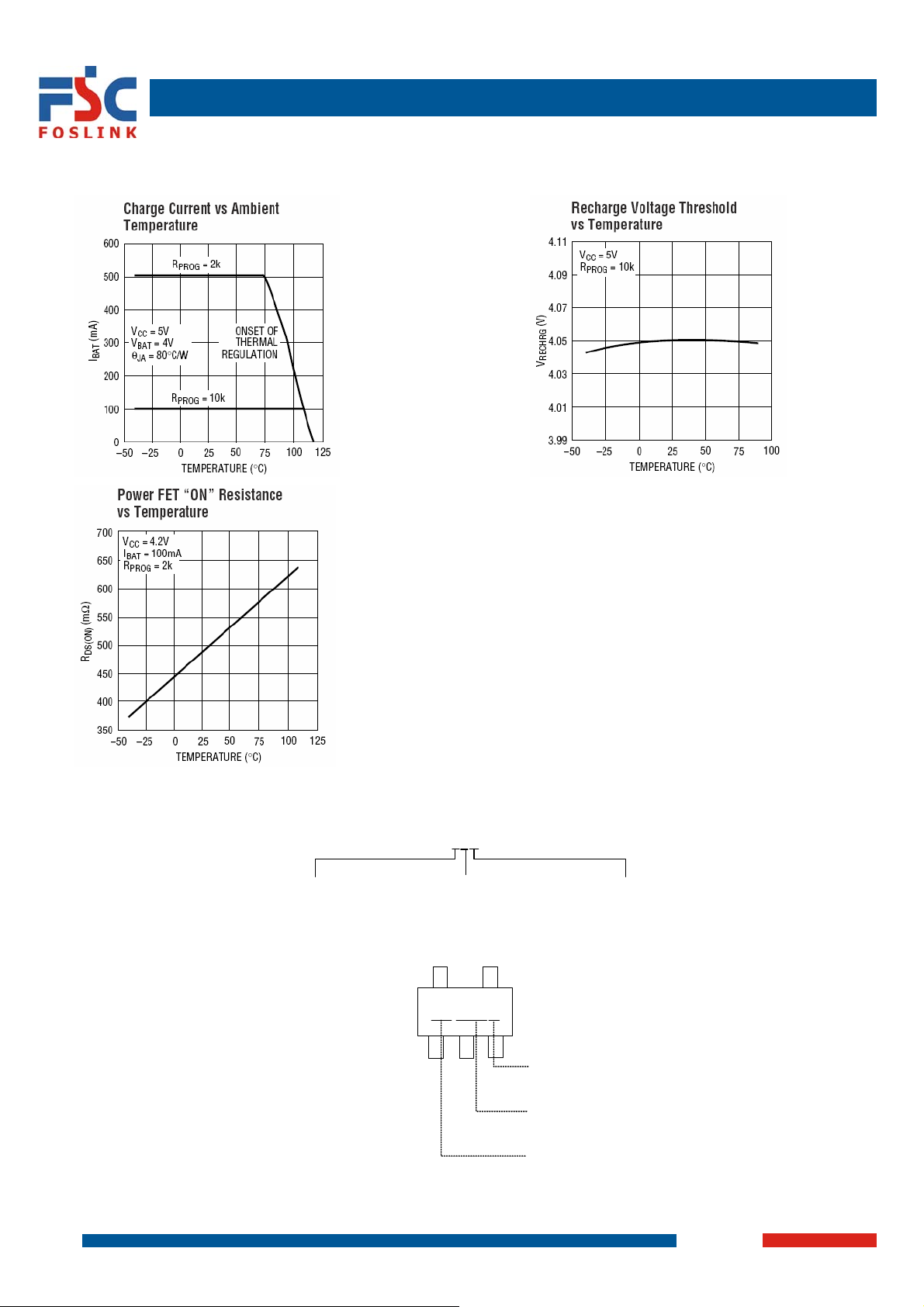
TYPICAL PERFORMANCE CHARACTERISTICS(CONTINUED)
FSP4054
12/15
2007-7-3
Page 13
Standalone Linear Li-ion Battery Charger with Thermal Regulation
TYPICAL PERFORMANCE CHARACTERISTICS(CONTINUED)
FSP4054
13/15
2007-7-3
Page 14
Standalone Linear Li-ion Battery Charger with Thermal Regulation
TYPICAL PERFORMANCE CHARACTERISTICS(CONTINUED)
ORDERING INFORMATION
Package Type:
TC: TSOT23-5L
A: Tape & Reel
FSP4054XXX
Packing:
MARKING INFORMATION0
14/15
FSP4054
Temperature Grade:
D: -40~85℃
XXYMX
Internal code
Date code:
Y: Year
M: Month (1~9, O, N, D)
Product Code
2007-7-3
Page 15
Standalone Linear Li-ion Battery Charger with Thermal Regulation
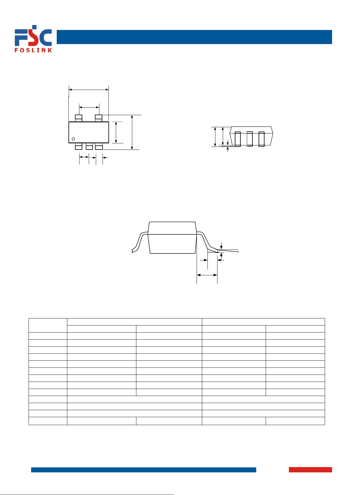
PACKAGE INFORMATION
Symbol
A 1.00 0.040
A1 0.000 0.100 0.000 0.004
A2 0.800 0.900 0.032 0.036
b 0.300 0.400 0.012 0.016
C 0.100 0.200 0.004 0.008
D 2.820 3.020 0.111 0.119
E 2.650 2.950 0.104 0.116
E1 1.500 1.700 0.060 0.068
L 0.300 0.600 0.012 0.024
L1 0.700REF 0.028REF
e 0.95 Bsc. 0.038 Bsc.
e1 1.90 Bsc. 0.076 Bsc.
θ 0
D
e1
5 4
e
E1
321
b
Dimensions In Millimeters Dimensions In Inches
Min. Max. Min. Max.
º
FSP4054
E
8º
L1
A
A2
A1
C
L
θ
0º
8º
15/15
2007-7-3
Page 16

 Loading...