

Page 1
Page 2
2
Page 3
table
of
conte
·s
Precision
Planetary
Contour
Contour
Beds .
.........
Performance.
Grinding
Grinding
Grinding
With
With
.
...... .................. .
. . . . . . . . . . . . . . . . . . . . . . . . 6
to
Location.
Grinding
Slot
. . . . . . . . . . . . . . . . 8
Head.
Grinder.
. . . . . . . . . 9
. . . . . . . . . . . 9
PACE
....
11
Accurate
Measuring
...........................
Head ............................
Specifications
Useful Accessories .
Programming
...... ..
. . . . . . . .
............
..................
.
..........
..........
. . . ....
. . . .
...
. . . . .
.........
........
PACE
12
. 14
..
18
20
20
A new
brought
Jig
Grinding Head
possible
All sta
conveniently
in
"trick" operations.
can be
sisting
angular
spindle
quick, accurate
irregular. Setting
except
stock
An infinite
60,000
degr
to 'precision
Grinders.
advantag
ndard
addition
locat
of
radii
and
and
for
rapidly
rpm
ee
of speed, convenie
grinding
This
combination of
with
Fosdick
es
never
jig
grinding
be
accomplished
to
many
which
Both
ed
and
ground
and
tangents
ind
exing device
the
slot
grinding
grinding
work
on a rotary
angular
and
range
surfaces.
makes
of
grinding
before
operations
straight
, as well as contours con-
of
contour
nce
in
the
Jig
Borer
available.
on
the Moore-Fosdick,
were
formerly
and
or
chordal
built
attachment
any
contour, regular
table
Chop
grinding
speeds -from
- allows accur~t~ control
and
Moore-Fosdick
the
unique
Tables
can
tapered
into
is
grinding
of
stock removal. Long-lasting precision is
quality
construction
and
by
many
features
capacity
Moore
makes
speedily
known
holes
surfaces.
the
The
main
permit
unnecessary
removes
even
faster.
12,000 to
grinding
assured
that
pro-
is
and
as
or
and
by
vide
dimensional stability,
heat
control.
The
machine
models,
accuracy
Model 30G
ventional
one
of
of
-+- .0001".
has a 36" x 18"
measuring
micrometers.
Model 42G
with
or
Direct
sions
reading
also
be
Models 44G
bases
equipped
Automatic
has a 44" x 22"
either
measuring
Dimension
are
simply
numerical
equipped
and
with
44" x 22"
with
Positioning is
( 44PG, 54PG ).
may
which
set
with
54G
Direct
including
be
ordered
comes
with
measuring
table
rods
~v1easuring,
from
dials.
This
Automatic
incorporate
and
54" x 22"
Dimension
available
in
hvo
table
and
the
in
and
model (
spindle-housing
any
one
sizes.
All
incorporating
rods
and
can
be
inside
with
blueprint
micrometers
which
to
42
Positioning.
our
most
tables.
Measuring
on
both
of
three
will
give
con-
inside
equipped
dimen-
direct-
PG)
can
advanced
They
are
and
machines
3
Page 4
•
-
?c
: .
• ·, . · 1
'
. .
. .
'(
.!
Page 5
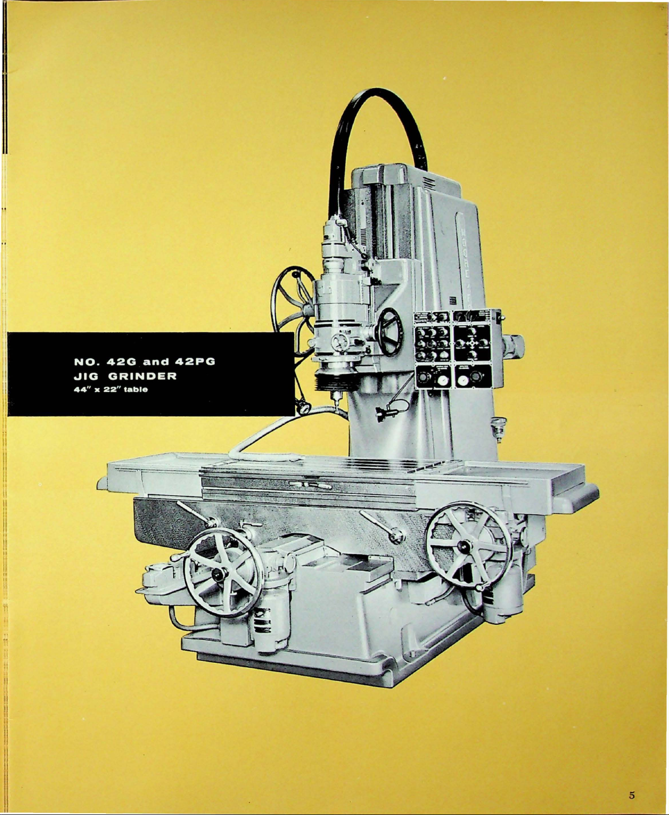
\
I
-
-=--=-~
"
"
.
----- -
,·
.. ,.
I
/
_,,.
5
Page 6
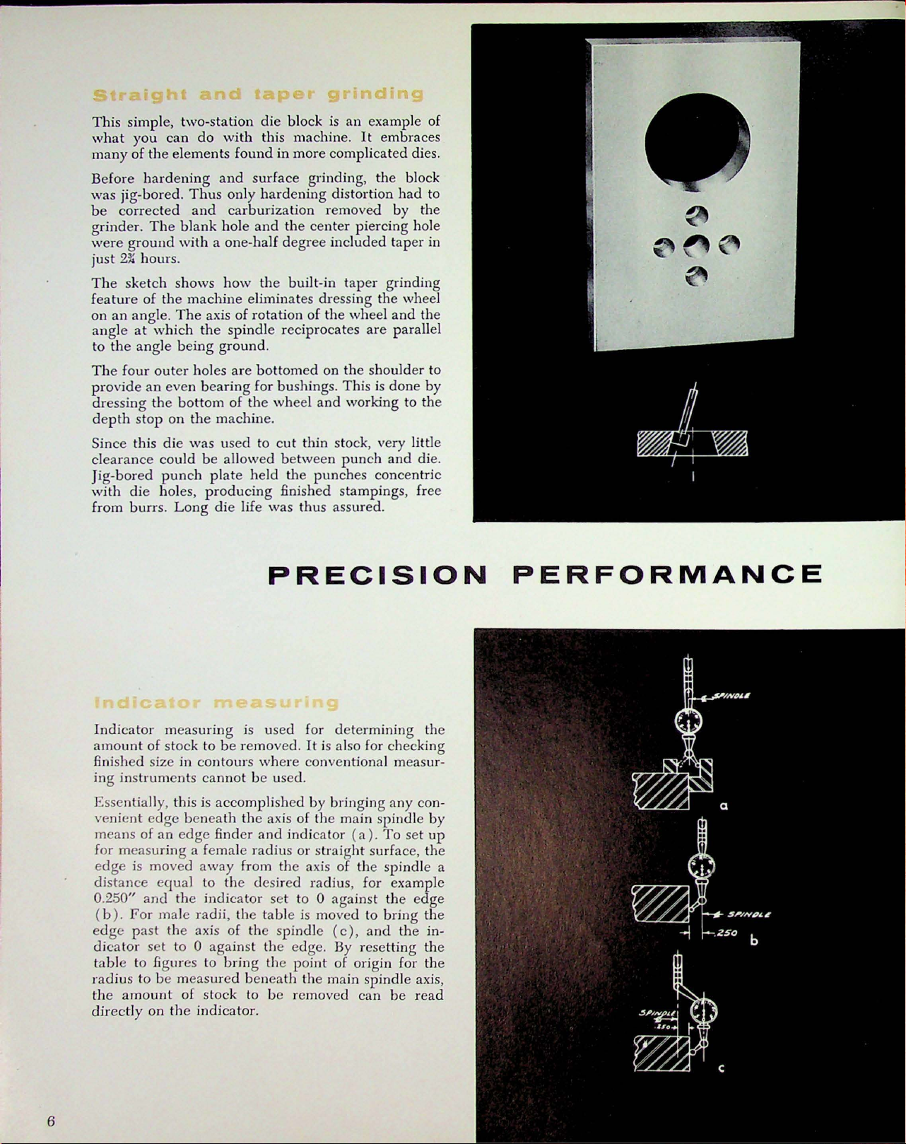
This
simple, two-station
what
)'OU
can
man)'
of
the elements
do
die
with
this machine. It
found
in
block
more
is
an
example of
complicat
embraces
ed
dies.
Before
was
be
grind
were grou11d
just
Th
feature
on
angle at
to the
The four
provide an
dr
de
Sin
clearance
Jig-bor
with die
from
hardening
jig-bored.
corrected
er. The
2¾
hour
e ske
of the
an
angle.
ang
essing the
pth
stop
ce
this die was u
ed
burrs. Long die life was
Thus
and
blank
with a one-half
s.
tch
shows
machine eliminat
The
axis
which
out
the
le be
ing
er holes
even be
bottom
on
the machin
could
hol
be allowed between pun
pun
ch plate held the
es,
producing
and
surface
only
hardening
carburiz
hole
and
how the built-in taper
of
rotation
spindle reciprocates
ground.
are
bottom
arin
g for
of the wheel and
e.
sed
to
grinding, the
distortion
ation
deg
bushings. This is
cut
finished
removed
the ce
nter pie
ree
included
es dres
thu
sing
of
the wheel and the
ed
on the
working
thin
sto
ck, very littl e
pun
ches conce
stampings, fr
s assUied.
PRECISION
block
had
by
rcing
tap
grinding
the wheel
are
parallel
should
done by
to th
ch
and
to
the
hole
er in
er to
e
die.
ntric
ee
PERFORMANCE
6
Indicator m
amo
unt
finished size in
ing ins
Esse
ntially, this is accompli shed by
ve
nie
nt edge
mea
ns of
for measu ring a female ra
ed
ge
is moved a
distan
ce equ
0.25
0" and the indicator set to 0
( b
).
For male
ed
ge:
past the axis of the s
di
ca tor set to 0
tabl e to
ra
diu
s to be measured beneath th
th
e a
mount
direct
ly
eas
urin
g is used for determining th e
of stock
trument
an edge
.figur
on the
to
be re
mov
contours wh
s cannot be used.
benea
th the axis
finder a
way
from the axis of tl
al to the desir ed radius, for example
radi
i, the table is moved
against the edge. By r
es to
brin
g th e po
of stoc
k to be removed c
indic
ator.
ed.
It
ere conve
of
nd indi
diu
s or straig
pind
is also for checkin g
nti
onal measur-
brin
ging
any
th e main s
cator (a ).
aga
le (
c), and the in-
int
of origin for the
e main
pind
To
set
ht surfa
inst the ed
1e
spindl
to
bring th
ese
tting
spind
an
ce, the
le axis,
be
le by
con-
up
e a
ge
e
the
read
Page 7
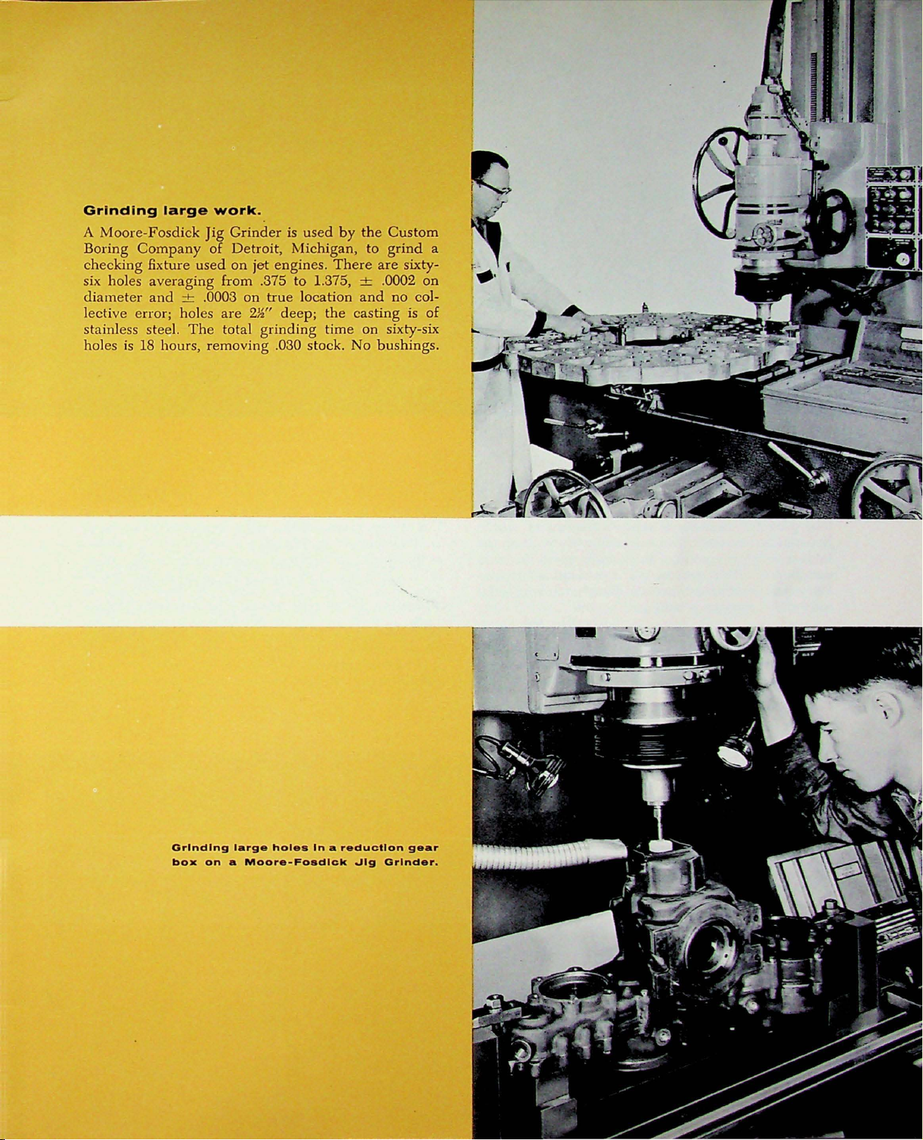
Grinding
A Moore-Fosdick
Boring
checking
six holes
diameter
large
Company
fixture
averaging
and
+ .0003
Jig
used
lective error; holes
stainless steel.
The
holes is 18 hours,
work
.
Grinder
is
used
by
of Detroit, Michigan,
on
jet
from .375
on
are
2½"
total
grinding
removing
engines.
true
deep;
.030 stock.
There
to
1.375, -+- .0002
location
the
time
the
Custom
to
grind
are
sixty-
and
no
casting
is of
on sixty-six
No
bushings.
a
on
col-
Grinding
box
large hol
on a Moore-Fosdick
es
In a reduction gear
J i g Gri
nder.
Page 8
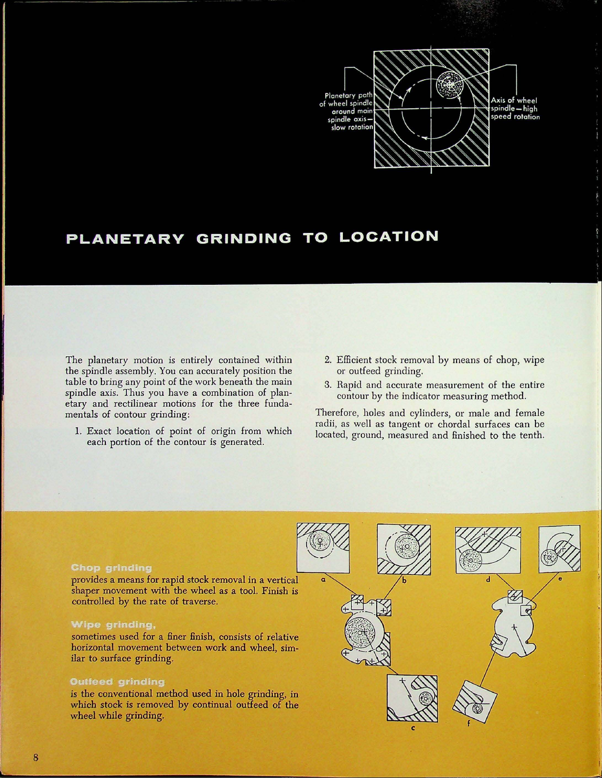
The
planetary motion
the
spindle assembly.
is
entirely contained within
You
can accurately position the
table to bring any point of the work beneath the main
spindle axis. Thus you have a combination of planetary
and
rectilinear motions for the three funda-
mentals of contour grinding:
1. Exact location of point of origin from which
each portion of
the
contour is generated.
2.
Efficient stock removal
or outf eed grinding.
3. Rapid
contour
Therefore, holes
radii,
and
accurate measurement of
by
the indicator
and
cylinders, or male
as
well as tangent or chordal surfaces can
located, ground, measured
by
means of chop, wipe
measming
method
and
and
finished
to
the
the
entire
.
female
be
tenth.
8
provides a means for rapid stock removal in a vertical
shaper movement with the wheel
controlled
by
the rate
of
traverse.
as
a tool. Finish is
sometimes used for a finer finish, consists of relative
horizontal movement between work
ilar
to
surface grinding.
is
the
conventional method used in hole grinding,
which stock is removed
by
continual outfeed of
and
wheel, sim-
in
the
wheel while grinding.
Q
C
Page 9
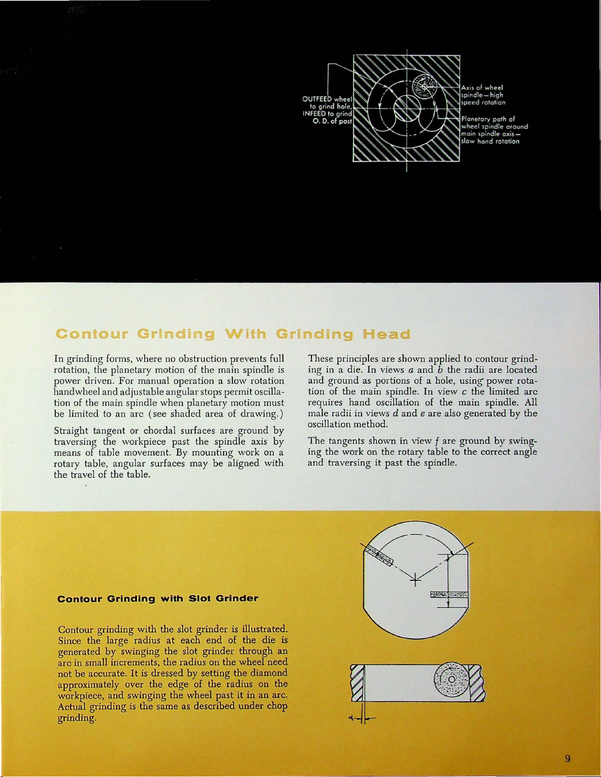
Contour
In
grinding forms, where no obstn1ction prevents full
rotation, the planetary motion of the main spindle is
power driven .
handwheel
tion of the main spindle
be
limited to an
Sh
·aight tangent or chordal surfaces are ground
tr
aversing the workpiece
means of table movement. By mounting work on a
rotary table, angul
the
travel of the table.
and
Grindi
For
manual operation a slow rotation
adjustable angular stops permit oscilla-
when
arc
( see
shaded
past
ar
surfaces
g
w·th
planetary motion must
area of drawing.)
by
the spindle axis
may
be
aligned with
by
G
ind"ng
These principles are shown applied to contour grinding in a die.
and
ground
tion of the main spindle.
requires
male radii in views d
oscillation method.
The
tangents shown in view f are
ing the work on the rotary table to the correct angle
and
h·aversing
Head
In
views a
as portions of a hole,
hand
oscillation of
it
past
and
and
e are also generated
the spindle.
b the radii are located
using
power rota-
In
view c the limited
the
main spindle. All
ground
by
by
swing-
arc
the
Contour
Contour grinding with
Since
generated
arc
in small increments,
·not
be
approximately over
workpiece,
Actual grinding
grinding.
Grinding
the
large radius
by
accurate.
and
swinging the slot grinder through an
It
is dressed
the
swinging
is
the
with
Slot
Grinder
the
slot grinder is illustrated.
at
each
end
of the
the
radius
edge
the
same as described
on
the
wheel
by
setting
of the radius on
wheel past
the
it
under
die
need
diamond
the
in
an
arc.
chop
is
Page 10
:_
: .
..
--,
;~
··
I
..
.. ..
:
,
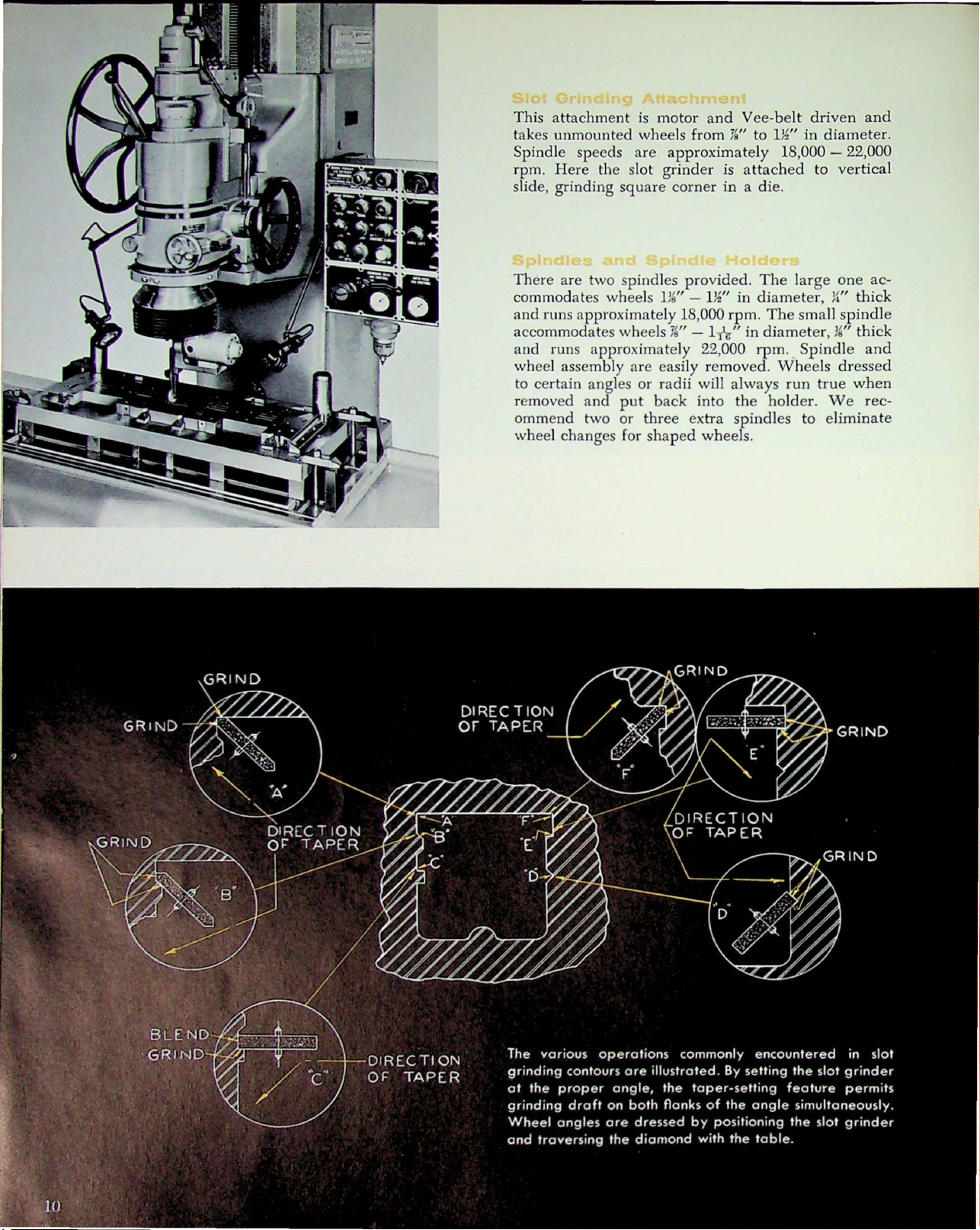
This
attachment
takes unmounted
Spindle speeds
rpm.
Here
slide, grinding
There
commodates wheels lJ'" -
and
accommodates wheels ¼" -
and
wheel assembly
to certain angles
removed
ommend two
wheel changes for
are
two spindles
runs approximately 18,000
runs approximately 22,000
and
is
motor
whee
ls from
are
approximate
the
slot gri
square
are
put
or
nder
corner
provided. The
easily removed.
or
radii will always
back
three extra spindles
shaped
and
l'"
is
in
l½"
rpm. The
lft
r'' in
into
the
wheels.
Vee-belt
to
ly 18,000 - 22,000
attached
a die.
in
diameter,
diameter,
rpm
driven
l½"
in
large
sma
..
Spind
·whee
run
holder.
to
diameter
to
vertica
one
W'
ll
spind
J'" thick
le
ls
dressed
true
We
eliminate
and
.
l
ac-
thick
le
and
when
rec-
Page 11
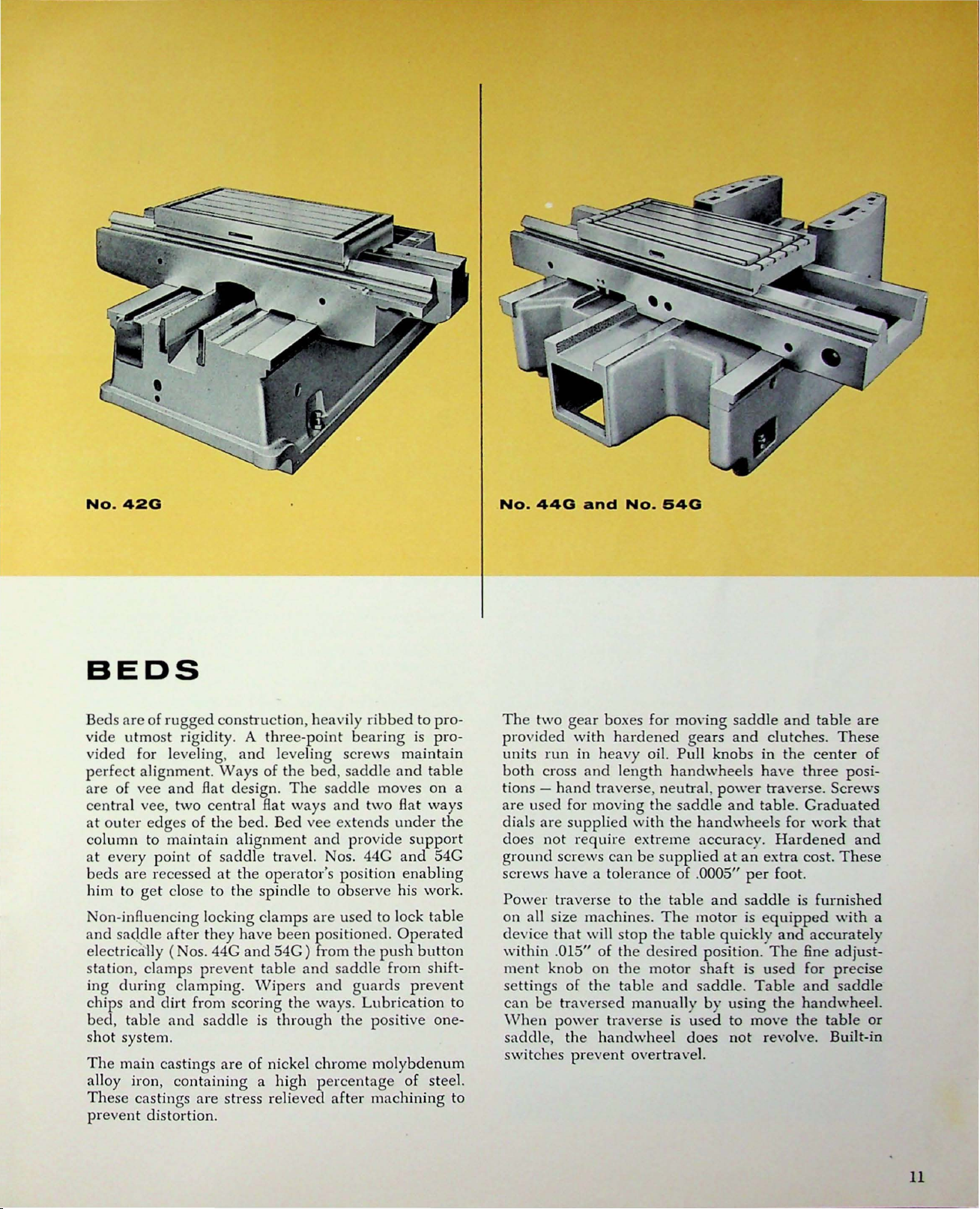
No. 42G
BEDS
Beds
are
of rugge
vide
utmost rigid
vid
ed
for level
perfect
are
ce
at
column
at eve
beds
him to
Non
and
el
stat
ing
c
hips and dirt
bed,
s
hot
The main
alloy iron,
These
prevent
ali
of
vee
ntr
al vee, two
outer
edges of
to
ry
are
get
-influ
sacJ_d
ectrica
·lly ( Nos. 44G
ion, cl
during
table
system.
castings
distortion.
gnment. Ways
point
recessed
encing
le
amps preven
castings
d co
nsb
·uction, h
ity. A
ing, and
and Rat
central
the
maintain
of sa
at the
clo
se
to the
locking
aft
er they
three-point
leveling
of
the
design. The
flat ways
bed
. Bed
alignment and
ddl
e travel. Nos. 44G
operator's positi on e
spindle
clamps
have been
and
54G)
t table
clamping. \,Vip
ers
from scori ng th e ways.
and
saddle
containing
are
is
through the positive one-
are
of
nickel
a high percent
stress reli
eved after mac
eavily r
bearing
screws main
bed, saddle a
sadd
le moves
and
two flat ways
vee
extends
provide
to obse
are
rve
used to lock
positioned. O
from th e
and
saddle
and
gua
Lubrication
chrome
molybde
age
ibb
ed
to
pro
is
pro-
tain
nd
table
on
under
the
support
and
54G
nabling
his work.
table
perated
push
button
from shift-
rds prevent
num
of stee
hining
a
to
l.
to
No.
44G
-
The
two
gear
provided
units
both
tions are
used for movin g the
dials
do
es
g
round
with
run
cross
hand
are supplied
not
require
screws
screws have a tolerance
Pow
er
trav
on a
ll size
device
within
ment
sett
can
\Vhen
knob
ings
be
that
.01
of
trav
pow
5"
saddle, the
switches preve
and
No.
54G
boxes for
hardened
in h
eavy
and length
mo,
gea
oil.
Pull
handwheels
traverse, neutral
sad
with
the handwh
extre
me
can
be
supplied
of
erse to the tabl e a
machines.
will
of the de
on the
the table
ersed
er
traverse
handwh
nt
The
stop the
sired
motor
and
manually
eel
ove
rtrave
table
is used to move the
does
·ing saddle
rs
and
knobs
and
clutch
in
the
have three
pow
er traverse. Screws
dle
and
table.
Graduated
eels for
accuracy
.0005"
motor
position .
shaft
saddle. Table
by
. Harden
at
an
extra cost. These
per
foot.
nd
saddle
is
quickly
is
is fw-nished
equ
ipp
and
The
used
fine
for
and
using the handwheel.
not
revolve. Built-in
l.
ta ble
are
es. These
center
of
posi-
work that
ed
and
ed
with
accurately
adjus
t-
precise
saddle
table
or
a
11
Page 12
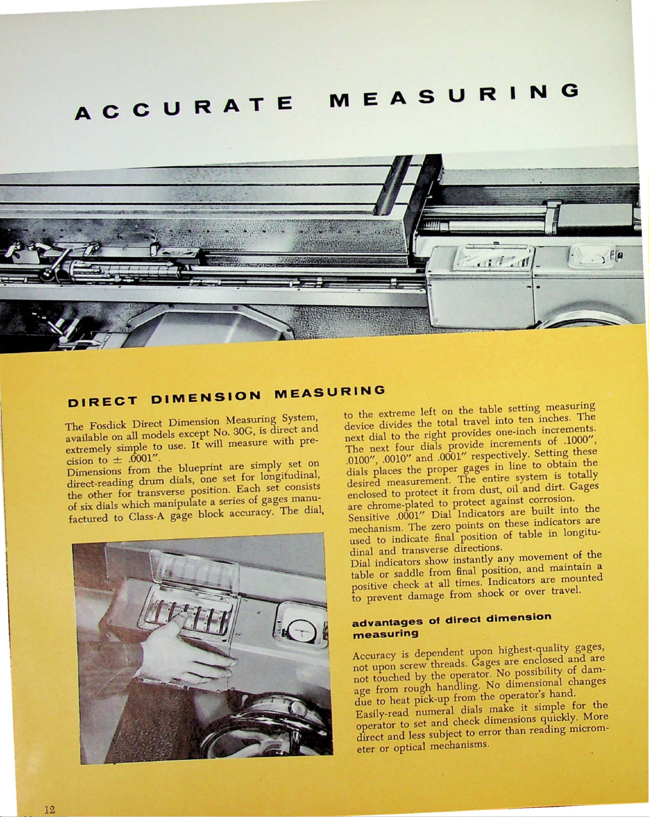
ACCURATE
MEASURING
DIRECT
The
Fosdick
available on all models
extremely simple to use.
cision to ± .0001".
Dimensions from
direct-reading
the
other
for transverse position.
of six dials which
factured to Class-A
DIMENSION
Direct
Dimension Measuring System,
the
drum
dials,
manipulate
gage
except
blueprint
MEASURING
No. 30G, is
It
will measure
are
one
set
Each
a series of gages manu-
block accuracy.
direct
with
simply
for longitudinal,
set consists
set
The
and
pre-
on
dial,
to the extreme left on
device divides
next dial to the right provides one-inch increments.
The
next four dials provide increments
.0100", .0010"
dials places the proper gages in line to
desired measurement.
enclosed to
are
chrome-plated to protect against corrosion.
Sensitive .0001"
mechanism.
used to indicate final position of
dinal
and
Dial indicators show instantly any
table or saddle from final position,
positive check
to prevent
advantages
measuring
Accuracy is
not
upon screw threads. Gages are enclosed
not
touched
age
from
due
to
Easily-read numeral dials make
operator
direct
eter
or optical mechanisms.
the
and
protect
The
transverse directions.
at
damage
dependent
by
rough
heat
pick-up from the operator's
to
set
and
less subject to error
the
table
setting
total travel into
.0001" respectively.
The
entire system is totally
it
from dust, oil
Dial
Indicators
zero points
all times. Indicators
from shock or over travel.
of
direct
the
operator.
handling. No
and
check dimensions quickly.
dimension
upon highest-quality gages,
ten
Setting
and
are
built
on
these indicators
table
movement
and
No
possibility of
dimensional changes
it
simple for
than
reading
measuring
inches.
dirt. Gages
are
The
of
.1000",
these
obtain
into
in
longitu-
of
maintain
mounted
and
dam-
hand.
microm-
the
the
are
the
are
More
a
the
12
Page 13
ROD
AND
BAR
MEASURING
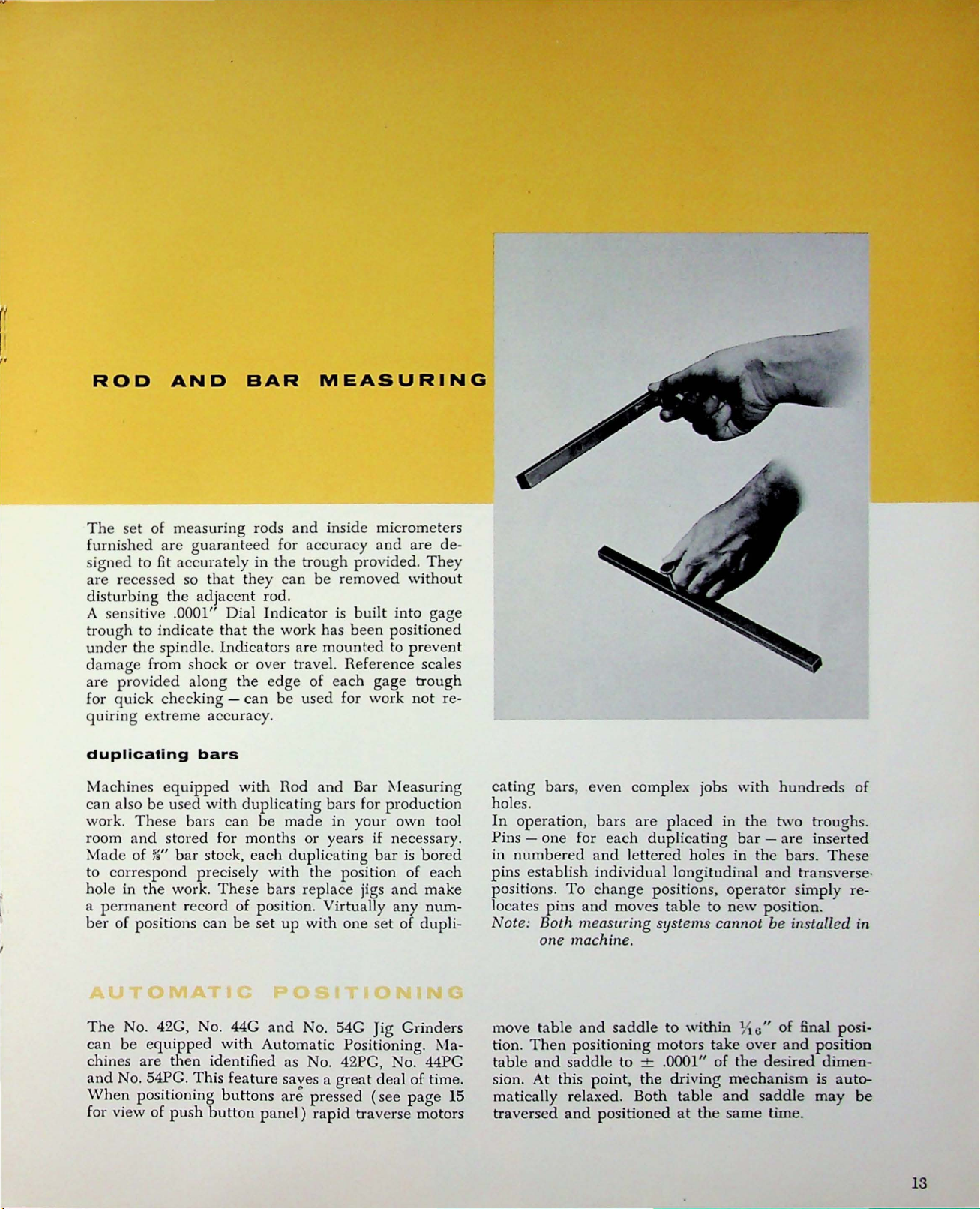
The set
furnished
signed
are
disturbing
of
measuring
are
to fit
accurately
recessed so
the
guaranteed
that
adjacent
A sensitive .0001"
trough
und
damage
are
for
quiring
duplicating
Machines
can
work. These
room
Made of
to
hole in
a pe
ber
to
indicate
er
the
spindle.
from shock
provid
quick
ed
checking -can
extr
eme
equipped
also
be
used
and
stored
fa"
bar
correspond
the
work.
rmanent
of
positions
along
accuracy.
bars
with
bars
stock,
precisely
record
can
rods
and
inside
for
accuracy
in
the
trough
they
can
be
rod
.
Dial
Indicator
that
the
work
has
Indicators
or
the
with
duplicating
can
for
months
each
These
of
be
are
mounted
over h·avel. Reference scales
edge
of
be
used
Rod
and
bars
be
made
or
years
duplicating
with
the
bars replace
position. Virtually
set
up
with
micrometers
and
provided.
removed
is
built
been
each
gage
for
work
Bar
for
in
your
if necessary.
bar
position
jigs
one
set
are
de-
They
without
into
gage
positioned
to
prevent
trough
not
re-
~feasuring
production
own
tool
is
bored
of
each
and
make
any
num-
of
dupli
-
eating
bars, even
holes.
In
operation, bars
Pins in
pins
positions.
lo
Not
one
numbered
estab
cates
pins
e:
Both
lish
To
one
for
each
and lettered
individua
change
and
moves
measuring
machine
complex jobs
are
placed
duplicating
holes
l lon
gitudinal
positions,
table to
systems
cannot
.
with
hundreds
in
the two troughs.
bar -are
in
the
and
operator
new
position.
inserted
bars.
transverse
simply
be
installed in
of
These
·
re-
The
No. 42G, No. 44G
can
be
equipped
chines
are
then
and No. 54PG.
When
for view of
positioning
push
and
with
No. 54G
Automatic
Jig
Grinders
Positioning. Ma-
identified as No. 42PG, No. 44PG
This
feature
buttons
button
saves a
are
panel)
great
deal
pressed ( see
rapid
traverse
of
page
motors
time.
15
move
tion.
table and
sion.
table
Then
At
this
and
saddle
positioning
saddle
point,
matically relaxed.
traversed
and
positioned
to
motors
-+-
the
Both
to
within
.0001"
driving
table
at
the
½
1.,"
take
over
of
the
desired
mechanism
and
saddle
same
of
and
time.
final posi-
position
dimen-
is
auto-
may
be
13
Page 14
HEAD
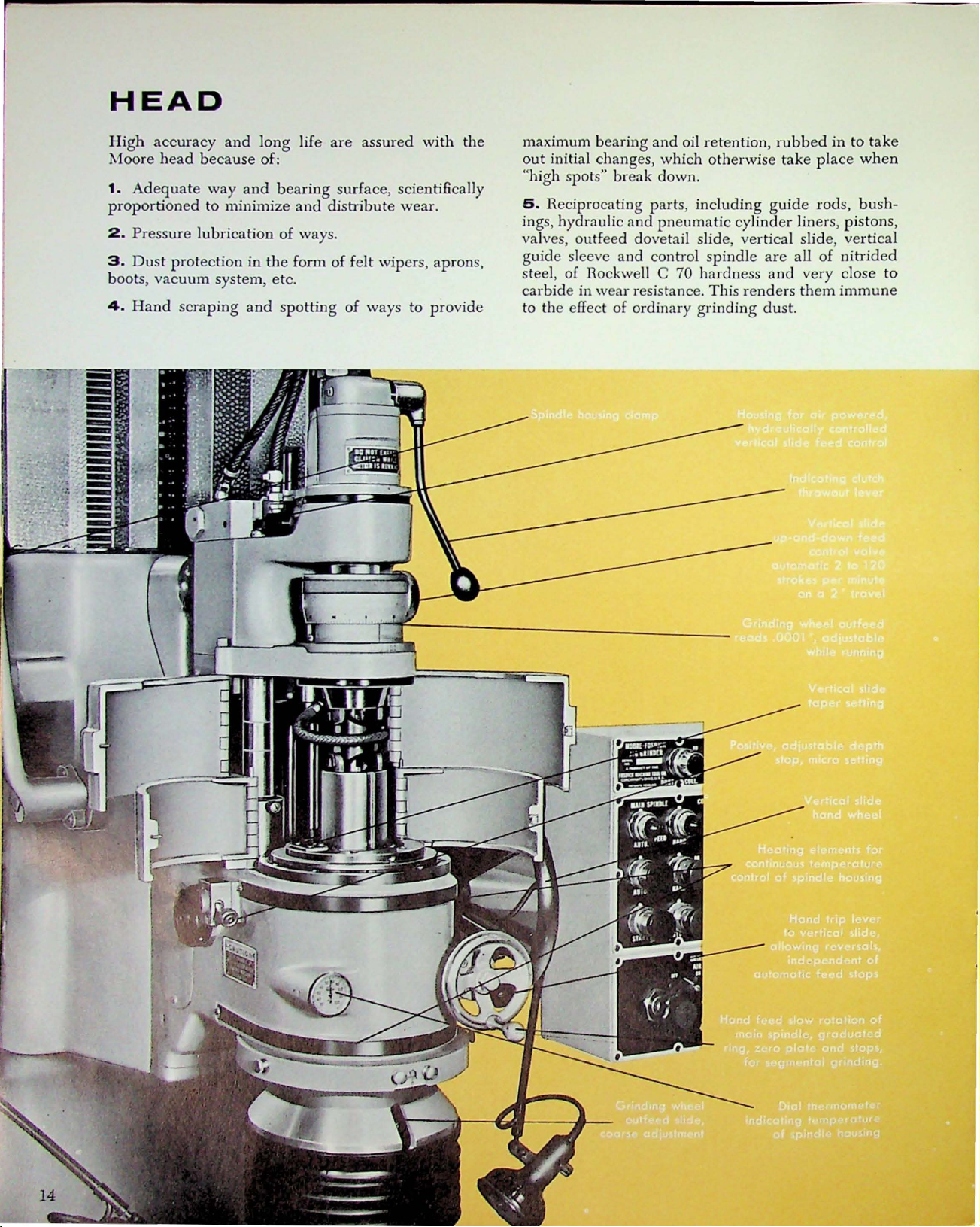
High
accuracy
Moore
1.
proportioned
2.
3 .
boots,
4.
head beca
Adequate
Pressure
Dust
protection
vacuum
Hand
scrap
and
long
use
of:
way
and
to
minimize
lubrication
in
system, etc.
ing
and
life
bearing
and
of
ways.
the
fom1
spotting
are
assured
surface, scientincally
distribute
of
felt wipers, aprons,
of
ways to
with
wear.
provide
the
maximum
out
initial changes, which
"h
igh spots"
5.
Reciprocating
ings, hydraulic
valves, outfeed dovetail slide, vertical slide,
guide
steel, of Rockwell C 70
carbide
to
the
bearing
sleeve
in
wear
effect
and
oil retention,
break
down.
parts, including
and
pneumatic
and
conb
·ol
resistance. This
of
ordinary
otherwise
cylinder
spindle
hardness
renders them
grinding
rubbed
take
place
guide
are
and
dust.
rods,
liners, pistons,
aU
very
of
in
to t
when
bush-
vertical
nitrided
close
immune
ake
to
Page 15
Control circuit,
switch, with
Hand
to
vertical
with
Motor
Pilot light shows
motor
or
automatic
slide
pilot
lights
stop-start
running
pilot
off-on
light
button
travel
----------l
Oust collector
on-off
Panel
on
If"
-------
Two convenience outlets
slot
grinder, light,
Four
speed
switch
!JS'eeds
to
90 • 120 · 180 • 240
Table
controls-traverse,
for
etc.
motor
selector
main
spindle-
rpm
position,clamps
Grinding
control
gage
and
ELEMENT
THERMOMETER
MAIN
~
INDICATING
PO I
NT
Of
SPINDLE
BEARINGS~
head
pressure
valve
- >
. ir.
air
regulator
I
l
11-----0UTFEEO
OOWNFEEO
HANO
WHEEL
Automatic
slide air control pressure
regulator
DI
AL
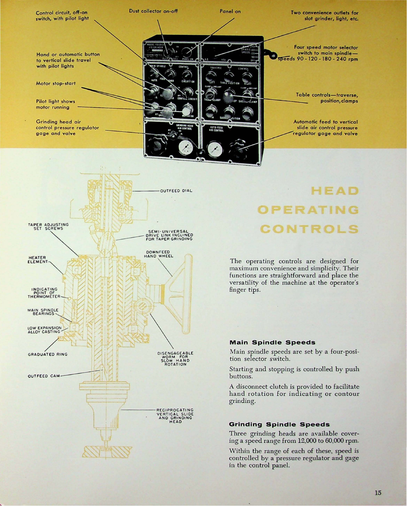
The
operating
maximum convenience
functions
are
versatility
fing
er
tips.
controls
straightforward
of
the
machine
and
feed
gage
are
designed for
simplicity.
and
at
the
to vertical
and
valve
Their
place
operator
the
's
~~~o~x
GRADUATED
OUTFEEO
0
l'tiT~
~
/
RI
CAM
t /
NG
Main
I
OISENGAGEABLE
WORM
FOR
SLOW
HANO
ROTATION
t-.fain
tion selector switch.
Starting
Spindle
spind
and
Speeds
le speeds
stopping
are
set
by
is controlled
a four-posi-
by
push
buttons.
A
disconnect
hand
rotation
clutch
for
is
provided
indicating
to facilitate
or
contour
grinding.
------
RECIPROCATING
V
ERTICAL
ANO
SLIDE
GRINDING
HEAD
Grinding
Spindle
Three grinding heads
ing a speed
Within the
controlled
in
the
range
from 12,000 to 60,000
range
by a
of
pressure
control panel.
each
Speeds
are
a\·ailable cover-
of
these,
regulator
speed
and
rpm.
is
gage
15
Page 16
Head
operating cont rols ,
(con
tin
ued)
O
utfeed
graduated
di
al
Outfeed
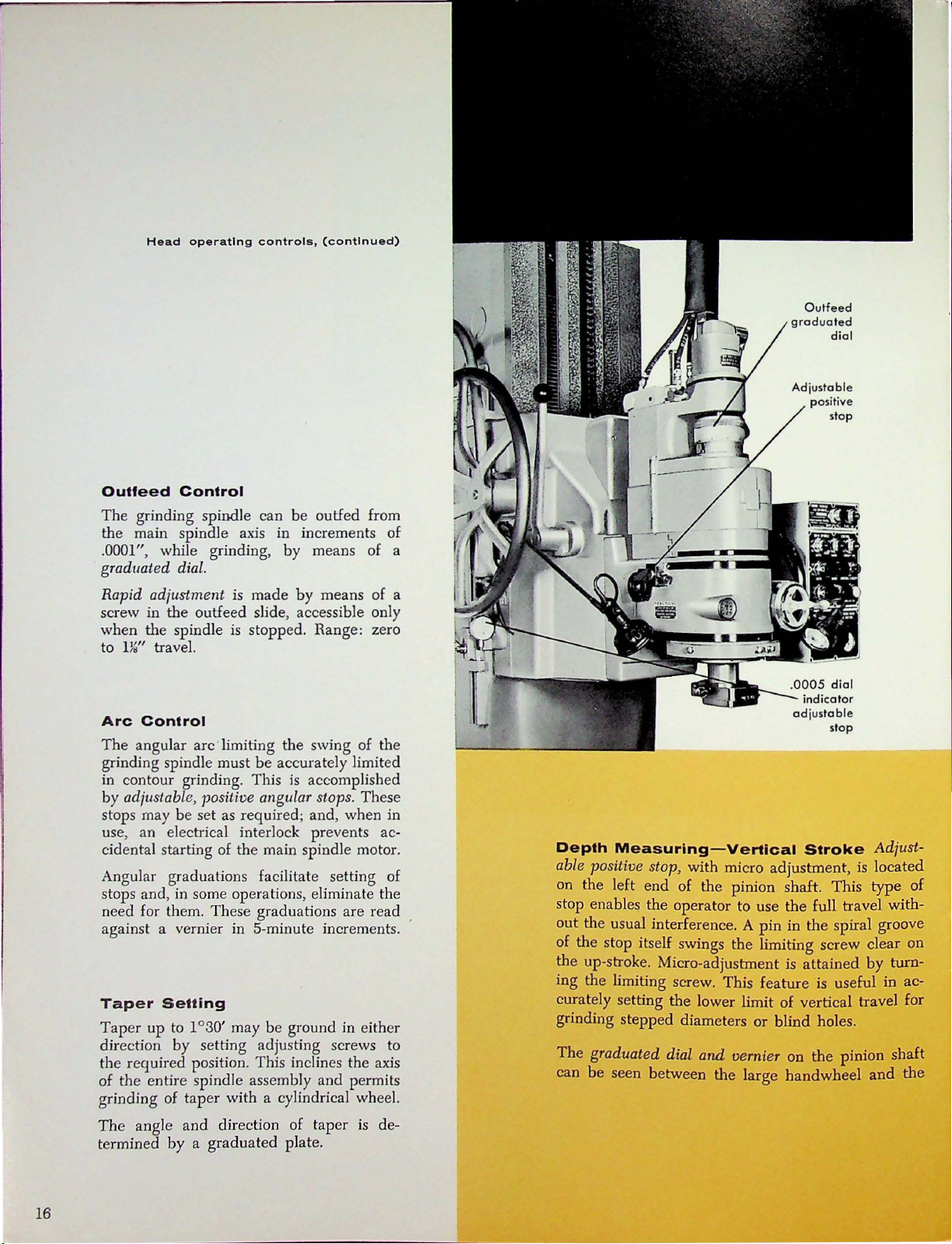
The
Control
grinding spindle can
be
outfed from
the main spindle axis in increments of
.0001", while grinding,
by
means of a
grad11ated dial.
Rapid
screw
when
to
A
The
grinding spindle must
in contour grinding. This
by
stops may
use,
adjustment
in
the
the
spindle
rn"
travel.
rc
Control
angular arc · limiting
is
made
by
means of a
outfeed slide, accessible only
is
stopped. Range: zero
the
swfog of the
be
accurately limited
is
accomplished
adjustable, positive angular stops. These
be
set as required; and, when in
an
electrical interlock prevents ac-
cidental starting of the main spindle motor .
Angular graduations facilitate setting of
stops and , in some operations, eliminate the
need for them . These graduations are read
against a vernier in 5-minute increments.
T
aper
Taper
direction
the
Sett
ing
up to 1 °30' may
by
setting adjusting screws to
be
ground in either
required position. This inclines the axis
of the entire spindle assembly and permits
grinding of taper with a cylindrical whee
l.
in
dicator
a
djustable
slap
Depth
Measuring
- V erti
cal
Stroke
Adjust-
able positive stop, with micro adjustment, is located
on the left
stop enables
out
the
end
of
the
pinion shalt. This
the
operator to use the full travel with-
usual interference. A
pin
in
the
type
of
spiral groove
of the stop itself swings the limiting screw clear on
the up-stroke. Micro -adjustment is
ing the limiting screw. This feature
curately setting
grinding stepped diameters
The
graduated dial
can
be
seen between
the
low
er
limit of vertical travel for
or
and
vernier on
the
large
attained
is
useful
blind holes.
the
pinion shaft
handwheel
by
and
turn-
in
ac-
the
16
The
ang
termined
le
and
direction of taper
by
a graduated pl
ate
is
de-
.
Page 17
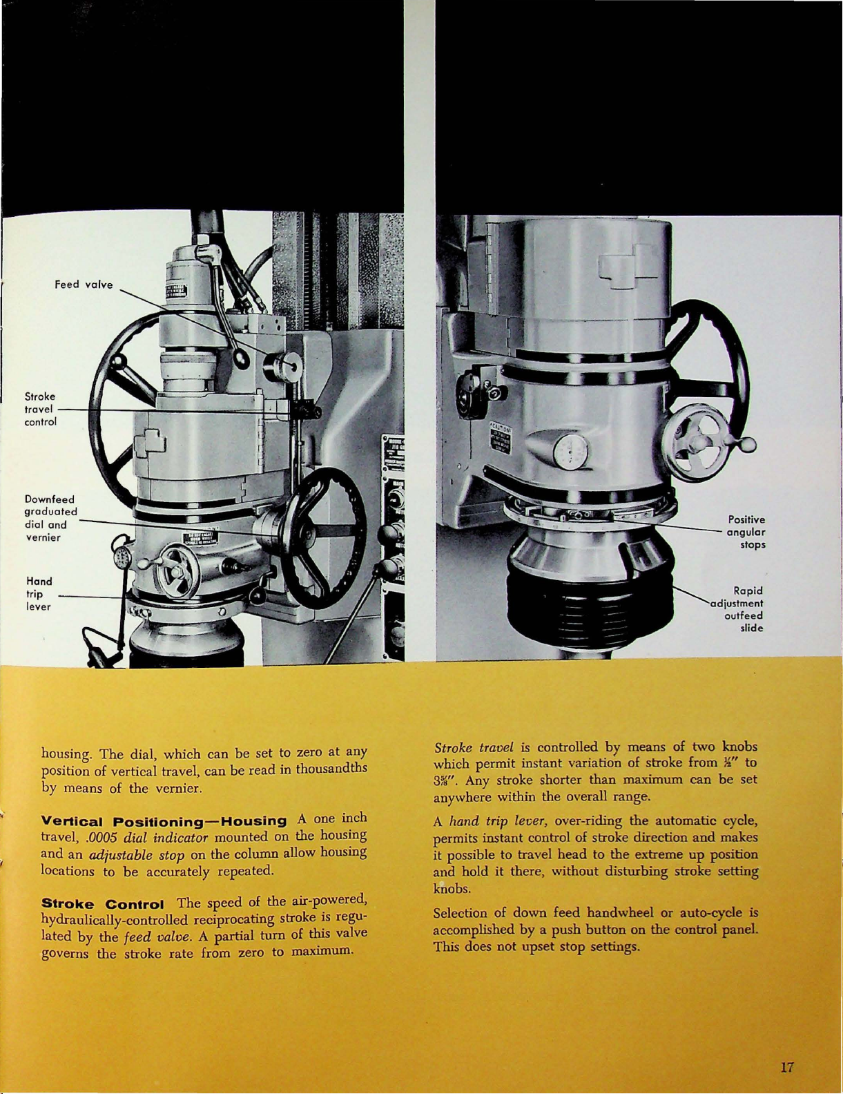
Feed
control
Downfeed
graduated
dial
and
vernier
valve
angular
stops
Hand
trip
lever
housing.
position of vertical travel, can
by
Vertical
The
dial, which can
means of the vernier.
Pos
iti
oning-Housing
be
set
to zero
be
read in thousandths
A one inch
at
travel, .0005 dial indicator mounted on the housing
and
an
adfustable stop on the column allow housing
locations to
Stroke
hydraulically-controlled reciprocating stroke
lated
by
governs
be
Control
the
feed
the
stroke
accurately repeated.
The
speed of the air-powered,
is
valve. A partial turn of this valve
rate
from zero to maximum.
any
regu-
Rapid
adjustment
outfeed
slide
Stroke travel
is
controlled
by
means of two knobs
which permit instant variation of stroke from ¼" to
3fs". Any stroke shorter than maximum can
be
set
anywhere within the overall range.
A hand trip lever, over-riding the automatic cycle,
permits instant control of stroke direction
it possible to travel head to
and hold
it
there, without disturbing stroke setting
the
extreme
and
up
makes
position
knobs.
Selection of down feed handwheel
accomplished
by a push
button
on
or
auto-cycle is
the
control panel.
This does not upset stop settings.
17
Page 18
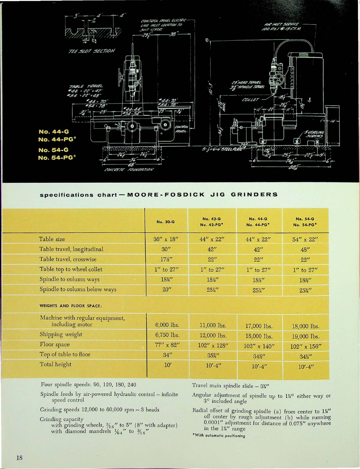
specifications
chart'-MOORE-FOSDICK
JIG
GRINDERS
No.
30-G
Table size
Table travel, longitudinal
Table travel, crosswise
Table top to wheel collet
Spindle to column ways
Spindle
WEIGHTS
Machine with regul
to
column below ways
AND
FLOOR SPACE:
ar
equipment,
including motor
Shipping weight
Floor space
Top of table to floor
Total height
Four
spindle speeds: 90, 120, 180, 240
36"
X 18"
30"
17½"
l"
to 27"
18½"
20"
6,000 lbs.
6,750 lbs .
77" X 82"
34"
10'
Spindle feeds by air-powered hydraulic control - infinite
speed control
Grinding speeds 12,000 to 60,000 rpm - 3 heads
Grinding capacity
wi
th grinding wheel
with diamond mandrels
s,
3/i
" to 5" (
O
¼-1
" to
8"
with adapter)
:½
"
6
No. 42-G
No. 42-
PG*
44" X 22"
42"
22"
l"
to 27"
18
½"
25¼"
11,000
lbs.
12,000
lbs.
102" X 128"
35~;"
10'-4"
Travel main spindle sli
Angul
ar
adjustment of spindle
3°
included angle
Radial offset of grindi
No. 44-G
No. 44-PG*
44" X 22"
42"
22"
l"
18½"
25W'
17,000 lbs.
18,000 lbs.
102" X 140"
34½"
10'-4"
de -3%"
ng
spindle
off center by rough adjustment
0.0001" adjustment for distance
in the lW' range
•w i
th
aut
oma
tic
positio
ning
to 27"
up
(a)
No.
54"
l"
18,000 lbs.
19,000 lbs.
102" X 156"
to
rn°
from
(b)
of 0.075"
No. 54-G
54-PG*
X 22"
48"
22"
to
27"
18½"
25¼"
34W'
10'-4"
either
way
or
center
to lW'
while running
anywhere
18
Page 19
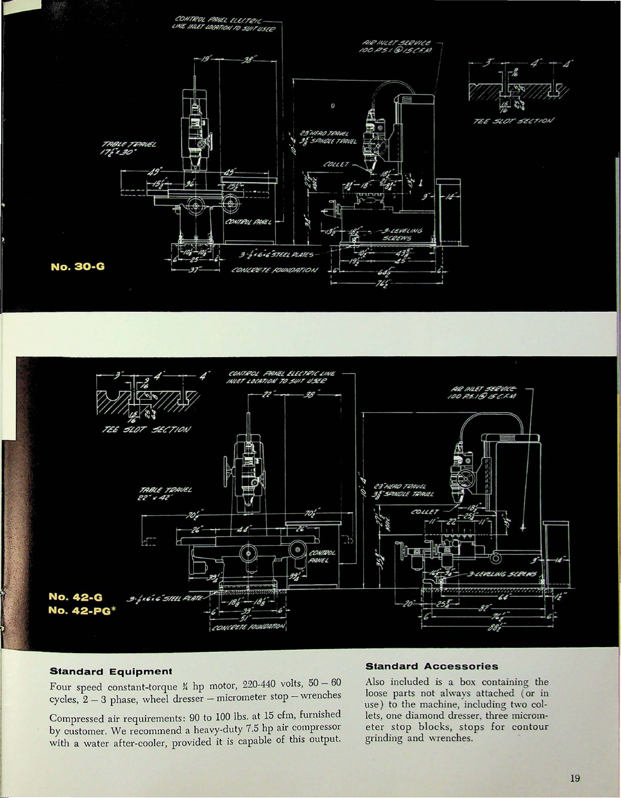
Standard
Four
speed
Equipment
constant-torque
Ji
hp
motor, 220-440 volts, 50 -
cycles, 2 - 3 phase, wheel dresser - micrometer stop
Compressed air requirements: 90 to 100 lbs.
by
customer.
with a water
We
recommend a heavy-duty 7.5
after-cooler, provided it
at
15
cfm, furnished
hp
air compressor
is
capable of this output.
60
-wrenches
Standard
Also included
loose parts not always
Accessories
is
a box containing the
attached ( or
use) to th~ machine, including two col-
lets, one diamond dresser, thr
eter
stop blocks,
grinding
and
wrenches.
stops
ee
for
micromcontour
in
19
Page 20

USEFUL
ACCESSORIES
To give maximum service, a machine such
Moore-Fosdick
equipped with small tools
Actual grinding time is short in proportion to handling, setting
search has been devoted to· the development of a
complete line of tools and accessories which will likewise reduce setting-up time
Grinder Job.
These include various types of holding, clamping and
measuring devices
grinding heads. Our line of accessories has been con-
Jig
Grinder
up
and gaging. Therefore, much re-
as
well as grinding wheels and
must
and
accessories.
and
facilitate every Jig
be
as
the
properly
PROGRAMMING
Moore-Fosdick Jig Grinders can
gramming by numerical control, using either tape or
card
systems.
System is easily adaptable simply by actuating the
drum
dials by motors. Programming equipment
The
Direct Dimension Measuring
be
arranged for pro-
stantly perfected by actual tests
us to offer the handiest set included
chine tool.
We
recommend the use, wherever possible, of
large, desk-type cabinet for convenient working
storage space. This provides a place for
sories necessary to the efficient operation
chine, including: Bolts
Grinding Heads, Wheels and whatever other equipment accumulates.
and key for all drawers
adjustable holder for blueprints or sketches.
needs vary widely, according to the type of work
be done. Each programming unit will
separately and adapted to the needs of
feature
is
an extra. Prices on application.
and
It
is equipped with a single lock
and
trial, enabling
with
the
of
Straps, Angle Plate,
and
doors
and a handy
be
considered
the
user. This
any
acces-
the
ma-
our
and
ma-
to
20
Page 21
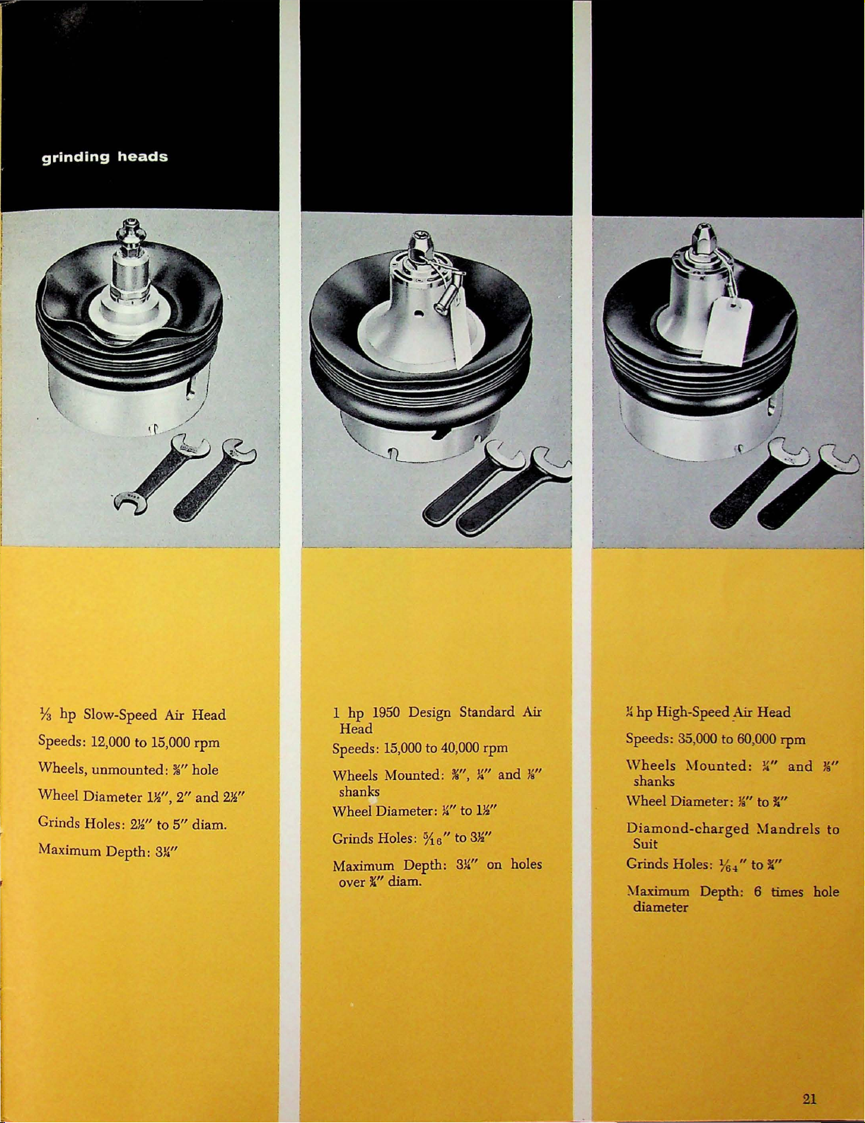
/
·- r,
~
~
½
hp
Slow-Speed
Air
Head
Speeds: 12,000 to 15,000 rpm
Wheels,
Whe
Grinds Holes: 2½" to
Maximum Depth:
unmounted:¾"
el Diameter l½",
3¼"
2"
5"
hole
and
diam.
-;;,
~ -.;-
,-
2½"
1
hp
1950
Design Standard Air
Head
Speeds:
15,000
to 40,
000
Wheels Mounted: ~".
shanks
Wheel Diameter:
Grinds Holes: ¾
Maximum Depth:
over
~,,
diam.
¾"
6
to l½"
" to
3¼"
rpm
¾"
and
3.½''
on holes
Js"
¼
hp
High-Speed _Air
Speeds: 35,000 to
Wheels
~[ounted
Head
60
,000 rpm
:
¾"
and
ls"
shanks
Wheel Diameter: W' to
Diamond-charged
l"
~Iandrels
to
Suit
Grinds Holes: ¼
~laximum Depth: 6 times hole
/'tor
diameter
21
Page 22
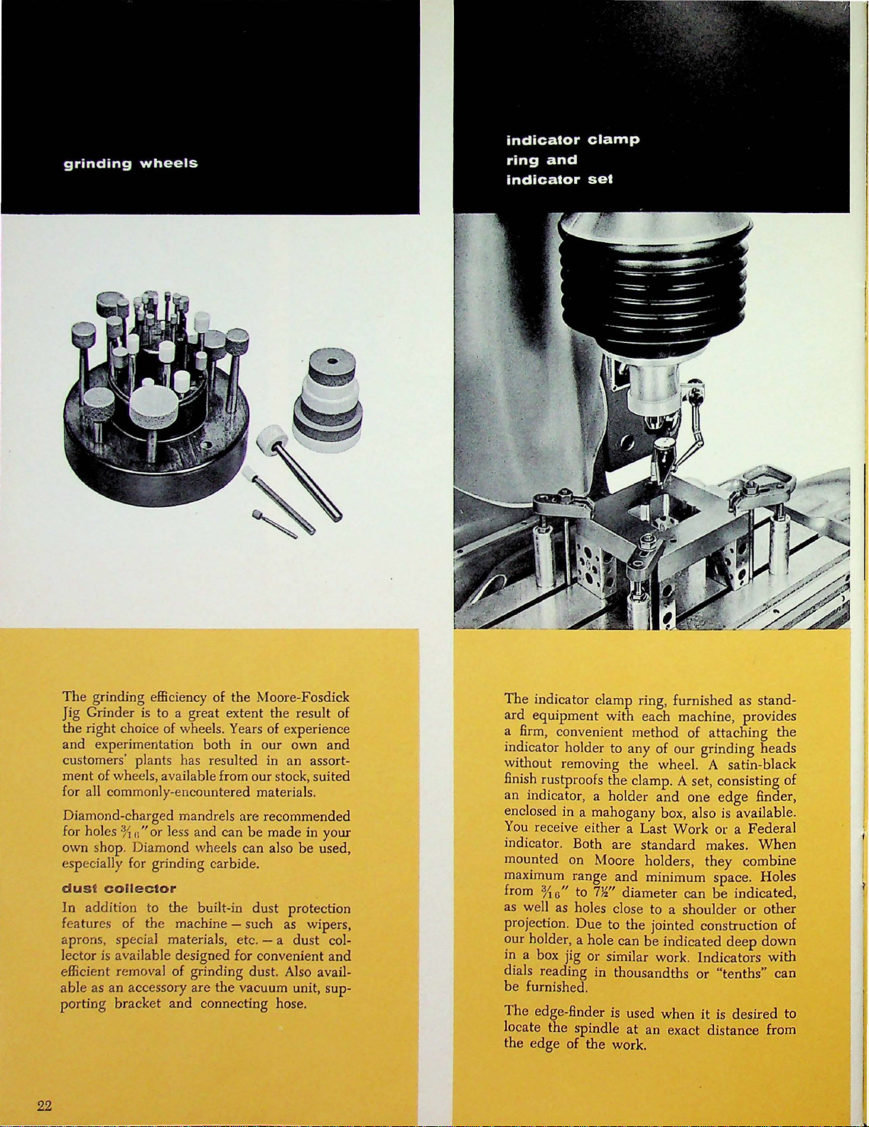
The
grinding efficiency
Jig Grind er is to a
the
right choice of wheels. Years of experience
and
experimentation
customers' plants has resulted in
ment
of wheels, available from
of
the
great
extent the result
both
in our own
Moore-Fosdick
an
our
stock, suited
for all commonly-encountered materials.
Diamond-charged
for holes
own s
especiall
dust
:H
11
hop
. D iamond wheels can also
y for grinding carbide.
collector
" or
mandr
le
ss and can
els
are
recommended
be
mad
In addition to the built-in dust protection
fea
tur
es
of
the machine - such as wipers,
aprons, special materials, etc. - a
le
ctor
efficie
nt
able
as
porting
is available
removal
an
accessory
brack
designed for conv enie
of
grinding dust. Also avail-
are
the
vacuum unit,
et
and
connecting hose.
dust
22
of
and
assort-
e in your
be
used,
col-
nt
and
sup
The
indicator clamp ring, furnished as
ard
equipment
a firm, convenient me
indicator holder to
without removing
finish rustproofs
an
indicator, a
with
any
the whee
the
clamp
holder
each mac
thod
of
our
. A set, consisting
and
hine
of
attachi
grinding
l.
A satin-black
one
stand-
, provides
ng the
heads
edge
finder,
of
enclosed in a mahogany box , also is available.
You
receive either a
indicator. Both
mount
ed on Moore holders,
maximum
from ¾o" to
range
7½"
as well as holes close to a shoulder
projection.
Due
our holder, a hole can
in a box jig
dials re
be
-
furnished.
The
edge-finder is used
locate
the
edge
ading
the
of
or
in thousandths
spindle
the
Last
Work
are
standard
and
minimum
diameter
to
the
jointed construction of
be
indicated
similar work.
when
at
an
exact
work.
or a Federal
makes.
they
space
can
be
deep
Indicators
or
"tenths"
it
is
distance
When
combine
. Holes
indicated,
or
other
down
with
can
desired
from
to
Page 23
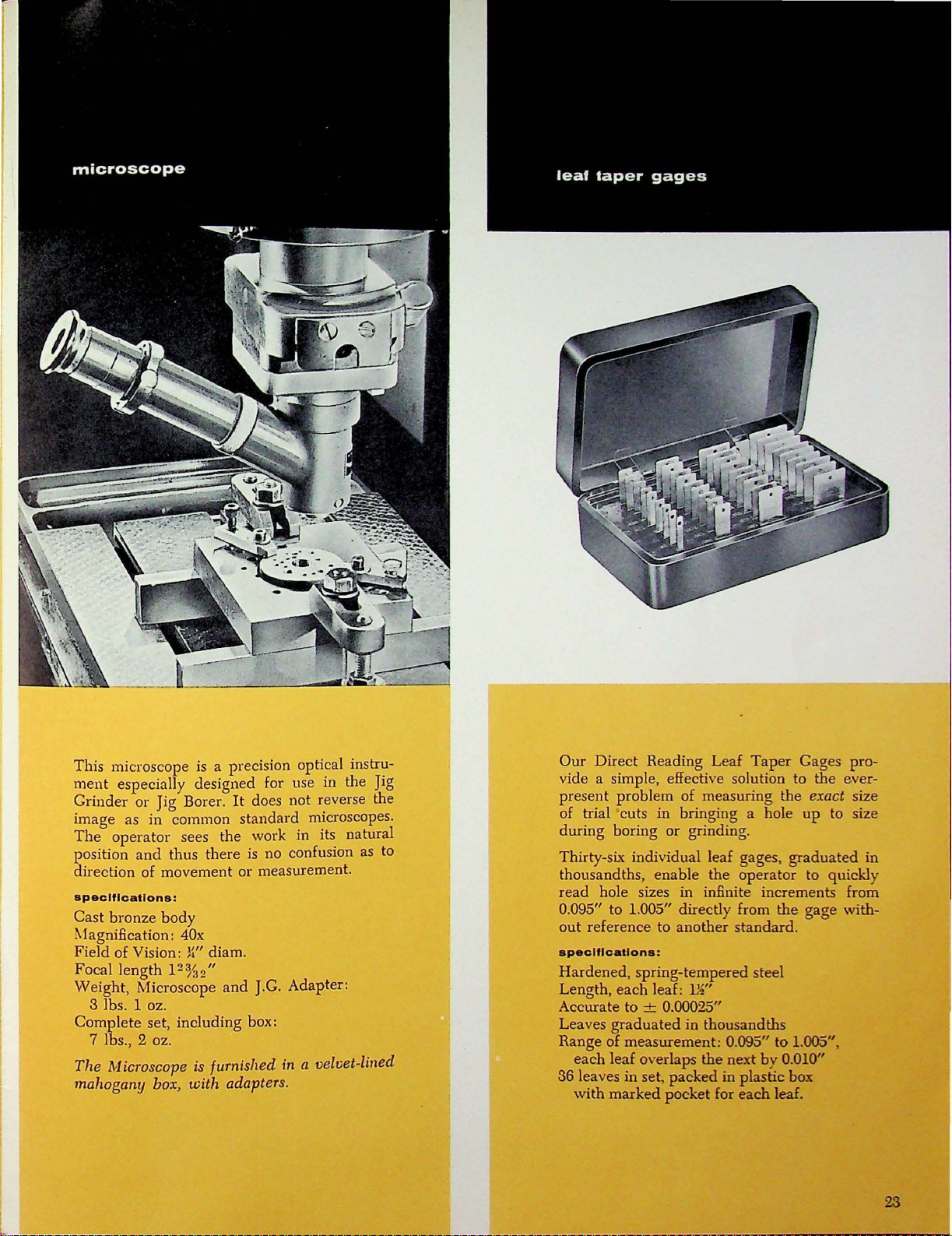
This
microscope is a precisi
ment
especially designed for use
Grinder
image
The
position
direction of
specifications:
Cast
or
as
in
operator
and
bronze
Jig Borer.
common
sees
thus
there
movement
body
Magnification: 40x
Field
of
Focal
Weight
Vision:
length
, Microscope
!2%
W'
diam.
"
2
3 lbs. 1 oz.
Complete
set, including box:
7 lbs., 2 oz.
The
Microscope is furnished
mahogany box,
with
on
optical instru-
It
does
not
standard
the
work
in
is
no
confusion as to
or measurement.
and
J.C. Adapter:
in
a velvet-lined
adapters.
in
the
Jig
reverse the
microscopes.
its natural
Our
Direct
Reading
Leaf
Taper
vide a simple, effective solution
present
of trial cuts
during
problem
in
boring
of
measuring
bringing a hole
or
grinding.
Thirty-six individual leaf gages,
thousandths,
read
hole sizes
0.095" to 1.005" directly from
out
reference
s
pec
ifi
cation
Hardened,
Length,
enable
in
infinite increments from
to
another
s:
spring-tempered
each
leaf:
rn"
the
operator
standard.
the
steel
Accurate to ± 0.00025"
Leaves
Range
36 leaves
each
with
graduated
of
measurement:
leaf
overlaps
in
set,
packed
marked
pocket
in
thousandths
0.095"
the
next
in plastic box
for
each
to
by
leaf.
Gages pro-
to
the
the
exact size
up
to size
graduated
to quickly
gage with-
1.005",
0.010"
ever-
in
23
Page 24
CINCINNATI
2 3 ,
0
HI
0
Litho In U.S.A.
3-57-5M
-ML
 Loading...