


U
Outdoor IP Security Camera
U
s
s
err
e
M
M
a
a
n
n
u
u
all
a
Model: SD2X
V1.0

Table of Contents
Security Warning .................................................................................................................................................. 1
1 Overview ........................................................................................................................................................... 2
1.1 Key Features ........................................................................................................................................... 2
1.2 Read before Use ..................................................................................................................................... 3
1.3 Packing Contents .................................................................................................................................... 3
1.4 Physical Description................................................................................................................................ 3
1.5 SD Card Management ............................................................................................................................ 4
1.6 Wall Installation ....................................................................................................................................... 5
2 Access the IP Camera in Foscam App .............................................................................................................. 6
2.1 Setting Up Your Camera:Wired Connection via Foscam App ................................................................ 6
2.2 Foscam APP Surveillance Window ........................................................................................................ 7
2. 3 Watch Live ............................................................................................................................................. 8
3 Access the Camera in the Web ......................................................................................................................... 9
3.1 Hardware Connection & Software Installation ........................................................................................ 9
3.2 Access the Camera in LAN ................................................................................................................... 10
3.3 Access the Camera in WAN.................................................................................................................. 11
3.4 Using the VLC Player ........................................................................................................................... 12
3.5 IP Camera Connection to the Server .................................................................................................... 14
3.6 Surveillance Software GUI .................................................................................................................... 14
3.7 Advanced Camera Settings .................................................................................................................. 23
3.8 Playback ................................................................................................................................................ 57
4 Surveillance Software Foscam VMS ............................................................................................................... 59
4.1 Hardware Connection & Software Installation ...................................................................................... 59
4.2 Software Installation .............................................................................................................................. 59
4.3 Create Acount ....................................................................................................................................... 60
4.4 Add Device ............................................................................................................................................ 61
4.5 Surveillance Software GUI .................................................................................................................... 64
4.6 Advanced Camera Settings .................................................................................................................. 70
5 Appendix ........................................................................................................................................................ 103
5.1 Frequently Asked Questions ............................................................................................................... 103
5.2 Default Parameters ............................................................................................................................. 109
5.3 Specification ........................................................................................................................................ 109
5.4 CE & FCC ........................................................................................................................................... 110
5.5 WARRANTY ......................................................................................................................................... 111
5.6 Statement ............................................................................................................................................ 113
6 Obtaining Technical Support ......................................................................................................................... 115

1
Security Warning
Please change the password of your camera regularly, using a combination of numbers, letters and
special characters.
We recommend that you regularly update your camera to the latest available software and firmware
versions to help ensure the best experience for your camera.

1 Overview
Foscam Outdoor IP Security Camera is an integrated IP Camera with a color CMOS sensor enabling
viewing in High Definition resolution.It combines a high quality digital video camera, with a powerful web
server, to bring clear video to your desktop from anywhere on your local network or over the Internet.
The IP Camera supports the industry-standard H.264 compression technology, drastically reducing file
sizes and conserving valuable network bandwidth.
The IP Camera is based on the TCP / IP standard. There is a WEB server inside which could support
Internet Explorer. Therefore the management and maintenance of your device is simplified by using the
network to achieve the remote configuration and start-up.
The camera is designed for outdoor surveillance applications such as courtyards, supermarket, and
school. Controlling the IP camera and managing images are simplified by using the provided web
interface across the network utilizing connectivity.
1.1 Key Features
Standard H.264 video compression algorithm to satisfy the transmission of high definition video in
narrow bandwidth network
2.0 Mega-Pixel
Supports IE / Firefox / Google / Safari browser or any other standard browsers
Supports WPA and WPA2 Encryption
Supports Pan & Tilt
Supports 18x Optical Zoom
6pcs Infrared-LEDs, night vision range up to 50 metres (164ft)
Supports image snapshot
Supports dual-stream
Supports 2.4G/5G dual band, IEEE802.11b/g/n/ac
Supports IR-Cut and the filter change automatically
Supports remote viewing & record from anywhere anytime
Multi-level users management with password protection
Motion detection alert via email or upload image to FTP
Supports multiple network protocols: IP、TCP、UDP、HTTP、HTTPS、SMTP、FTP、DHCP、RTSP、
ONVIF
Providing Video Management Software to manage or monitor multi-cameras
Supports Wide Dynamic Range
Supports sound detection
Supports IP Filtering
Supports Alexa
Supports Google Assistant
Supports 128G Micro SD Card Storage(External)
3
1.2 Read before Use
● IP Camera × 1
● Power Adapter × 1
● Quick Setup Guide × 1
● Ethernet Cable× 1
● Mounting Plate × 1
● Wi-Fi Antenna× 1
Please first verify that all contents received are complete according to the Package Contents listed below.
Before the Network Camera is installed, please carefully read and follow the instructions in the Quick
Setup Guide to avoid damage due to faulty assembly and installation. This also ensures the product is
used properly as intended.
1.3 Packing Contents
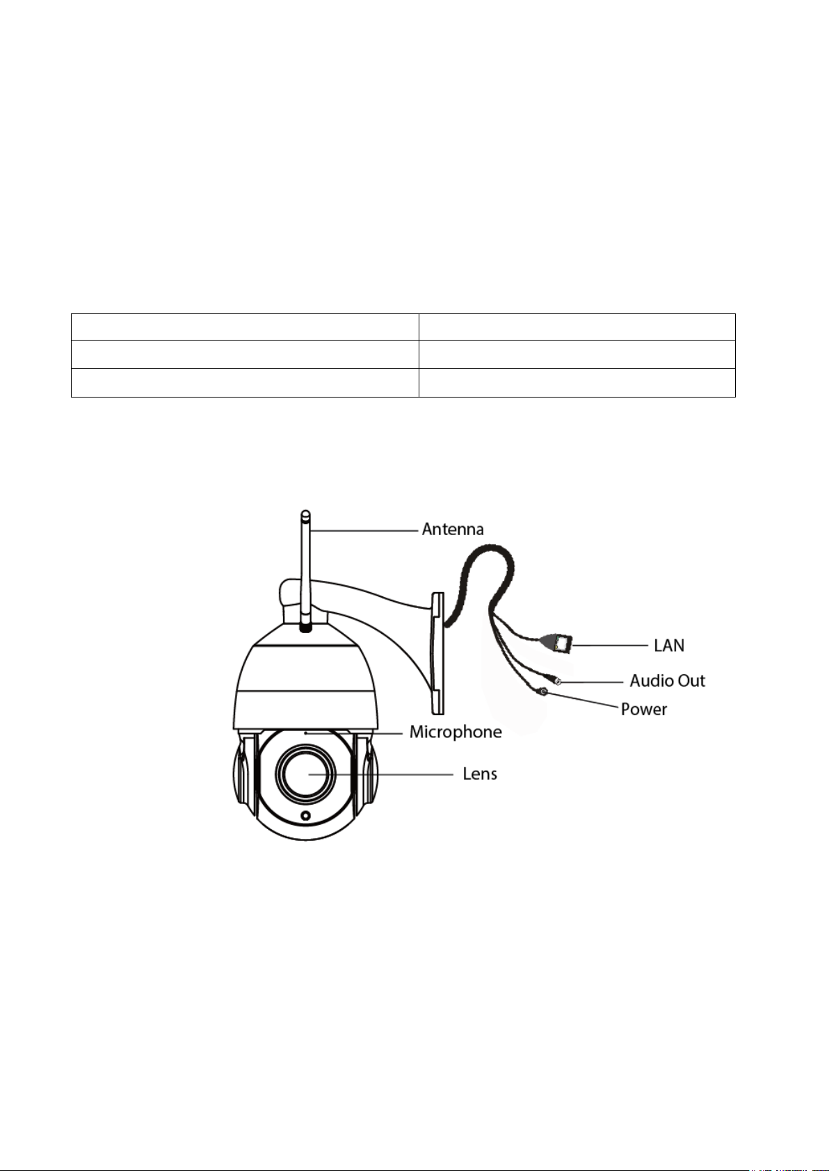
1.4 Physical Description
Antenna: Wireless Antenna
LAN: 10/100M adaptive Ethernet interface. Through this interface, IP camera can be connected with
various network devices, such as hub, router, etc.
Microphone: Built-in Microphone.
Audio Out interface: The jack is used to plug external output device such as loud speaker directly. Here
speaker cannot directly insert to the interface, it must connect to adapter first.
Power: Connect the external power adapter, request for 12V / 2A power.
Lens: High Definition Color CMOS Sensor with zoom lens.
4
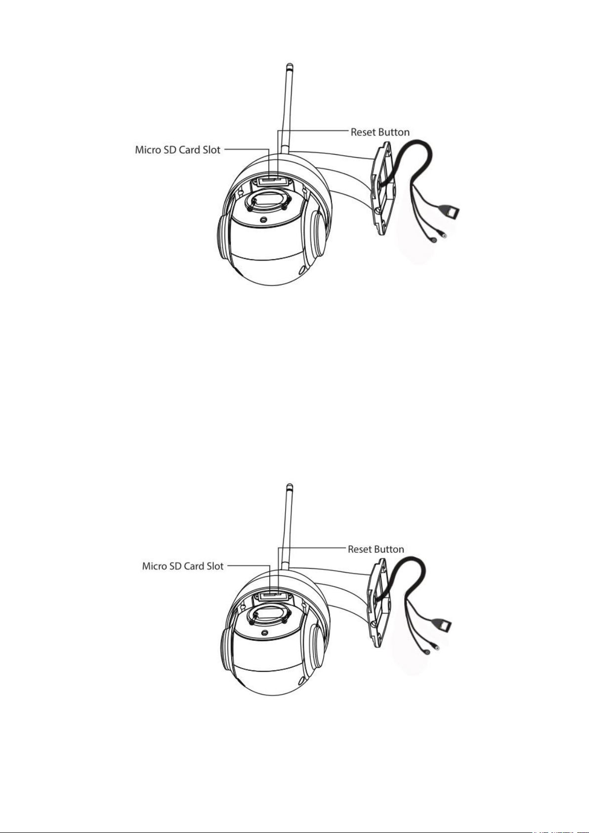
Reset Button
Press and hold on the reset button for 5 seconds. Releasing the reset button, the password will back to
the factory default administrator password. The default administrator user is admin with random
password.
Micro SD Card slot: Supports up to 128GB SD card for storing the video.
NOTE: There are up to two labels located at the bottom of the camera, this is an important feature of
original Foscam cameras. If your camera does not have labels, it may be a clone. Cloned Foscam
cameras can not use original firmware and are not eligible for warranty or technical services.
1.5 SD Card Management
The record files of the IP camera can be stored in the Micro SD Card.
This camera supports Micro SD Card and the max size of Micro SD card must be under 128G.
You need open the cover, then plug the Micro SD card into Micro SD card slot inside the IP camera.
5
When you plug in the Micro SD card during the camera work process, please reboot the camera again,
or else the Micro SD Card may be cannot work well.When you re-install the cover, please ensure the
tightness with the camera.
Warning: Please lock the cover in time after installing the Micro SD card to avoid water or water vapor
fall into the equipment then cause damage or lens fog.
1.6 Wall Installation
Please refer to the Quick Setup Guide.
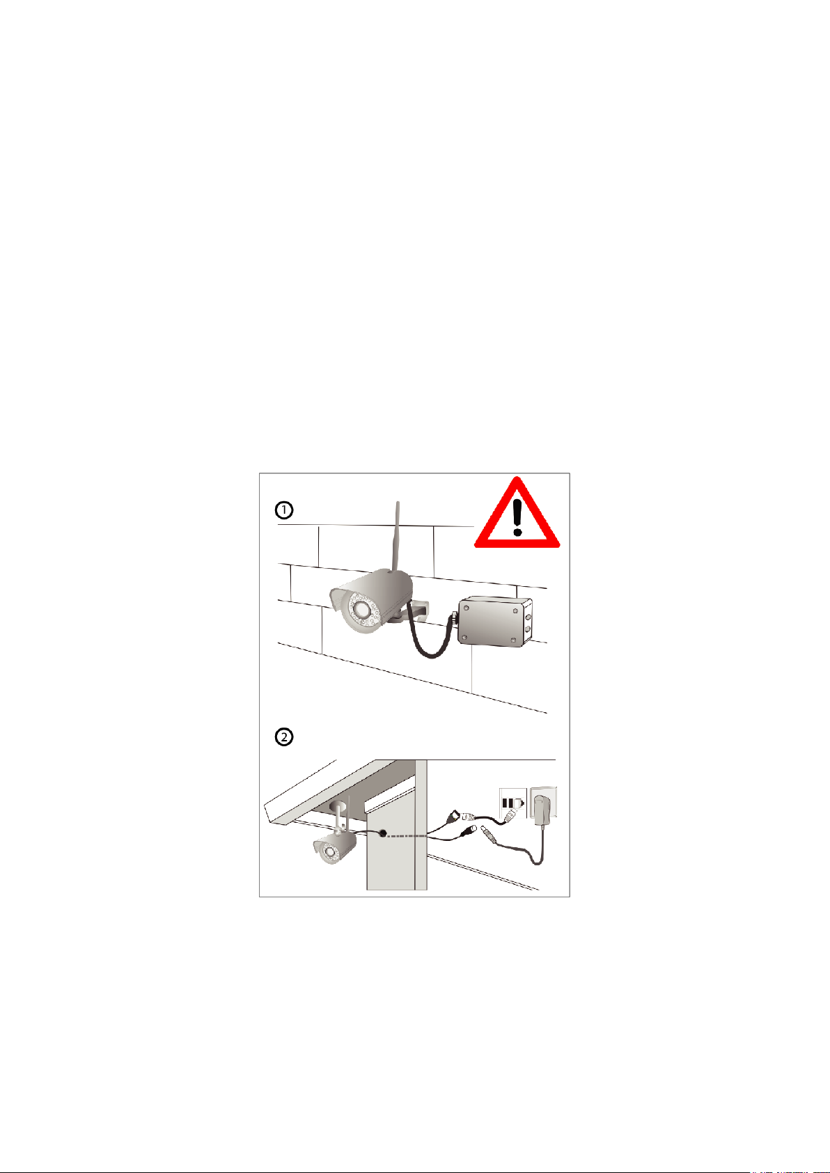
NOTE: Ensure that the rain or water will not reach the connector ports at the end of the pig tail wiring.
These connectors are not weather-resistant.
The cable of an outdoor camera should, from the position where the cable is divided into several cables,
be fitted dry. Install the cable into a waterproof junction box (1) or bring the cable indoors (2).

6
2 Access the IP Camera in Foscam App
2.1 Setting Up Your Camera:Wired Connection via Foscam App
Download and open the Foscam App from the App Store or Google Play Store. Once open, please
register for a Foscam account, or sign in if you have one already.
1. Please mount the antenna and make sure it is in a vertical upright position.
2. Connect the camera to your Internet router using an Ethernet cable.
3. Connect the power adapter to the camera.
4. Run the Foscam APP.
5. Under “Foscam” select “Tap to add a camera” and then select "Camera", after that scan the QR code,
which is located at the bottom of your camera (see illustrations below).
6. On the “Choose Setup Method” screen, confrm that “Wired” is selected (upper-left corner) and tap
“Ready for Wired Connection.” Wait a few moments for a message confrming that the setup process has
been completed (see illustrations below).
7
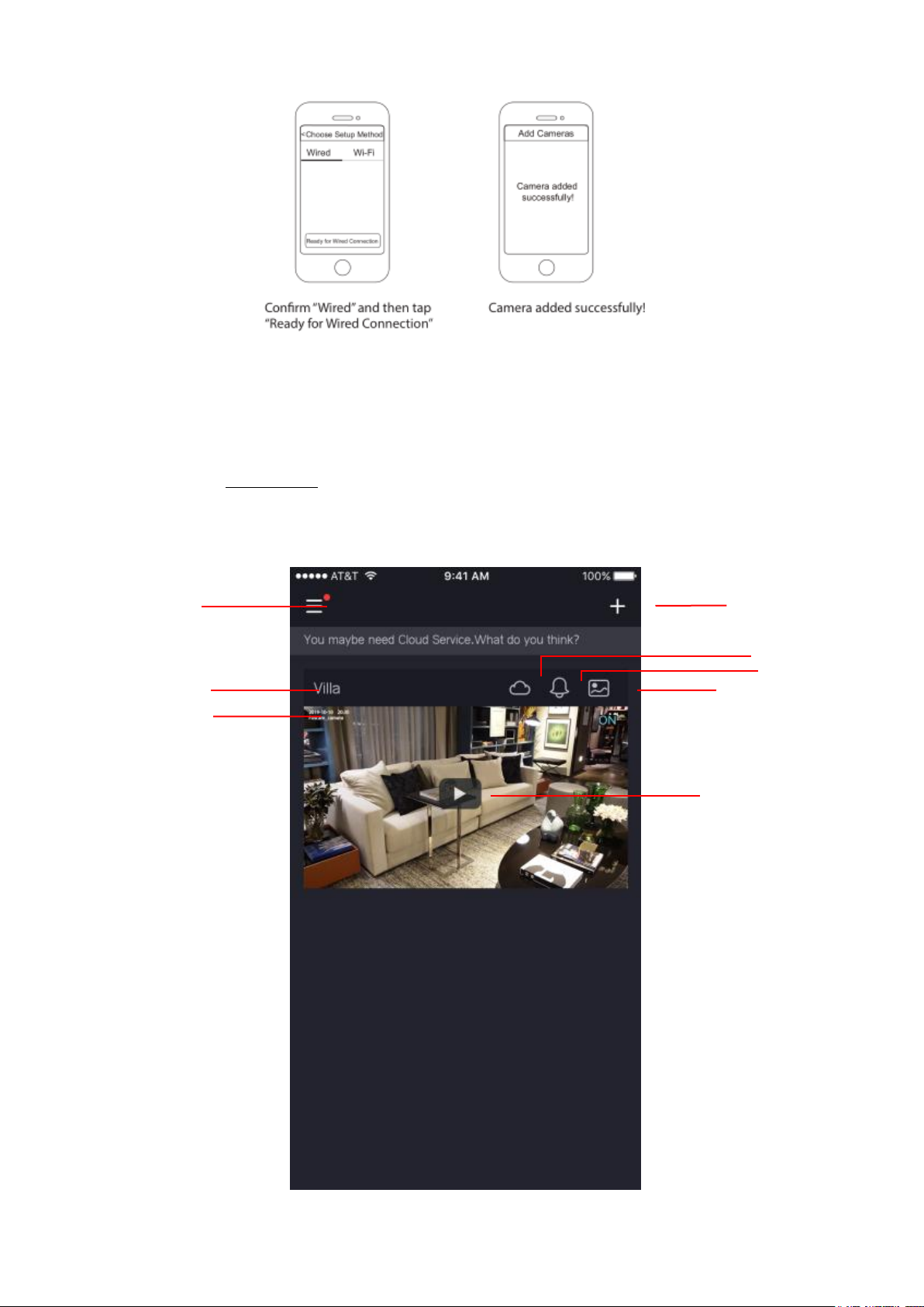
Menu
Camera Name
Camera Date&Time
Add Device
Cloud Service
Alerts
Album
Watch Live
2.2 Foscam APP Surveillance Window
Please refer to the section 2.1.1 if you install the camera for the first time. You can start to learn about
software
operation after finish quick installation.When you launch the Foscam App, the devices page displays.
Camera Name: A camera name which is displayed in the Foscam Cloud Service.

8
You can rename your camera‟s name by tap Live > Camera Settings > Camera Info .
Back
Speaker / Mute the audio
Resolution
Snapshot
Bit Rate
Camera Setting
Full screen
More Function
Flip
Two-way audio
Cloud Service Subscription
Date
Timeline
Mirro
IR LED Schedule
Pan / Tilt control
OSD: Including camera name and camera time, camera name can not be renamed but camera time can
be in synchronized with the phone.
Sync Time: Tap Live > Camera Settings > Sync Time .
2. 3 Watch Live
Tap Live to view and listen to a live video
Back: To stop viewing and listening to the live feed, tap the Back
Resolution: There are three types to identify different streams you have set. If select the FHD Mode, the
clearer video will become, and it will take up more bandwidth; If select the SD Mode, the video will not be
as cleaar as FHD Mode, and it will take up less bandwidth. The HD Model is a value between FHD Mode
and SD Mode.
Bit Rate: Generally speaking, the larger the bit rate is, the clearer video will become. But the bit rate
configuration should combine well with the network bandwidth. When the bandwidth is very narrow, and
9
bit rate is large, that will lead to video can not play well.
On this screen, you can listen to a live stream, record clips, take a snapshot, activate two-way talk or full
screen.
If you want to catch the smaller details, pinch and drag any image as you do with photos on your
smartphone
IR LED Schedule: On this page, you can enable/disable the IR LED, and set the IR auto switch or you
can schedule it.
Auot: As default, the IR-Cut auto switch is ON, it means that the IR LED will be OFF during 9:00~18:00,
and the IR LED will be ON at the other time.
Day: it means that the IR LED will be OFF all the time.
Night: it means that the IR LED will be ON all the time.
Schedule: You can schedule the time to turn the IR LED OFF/ON.
3 Access the Camera in the Web
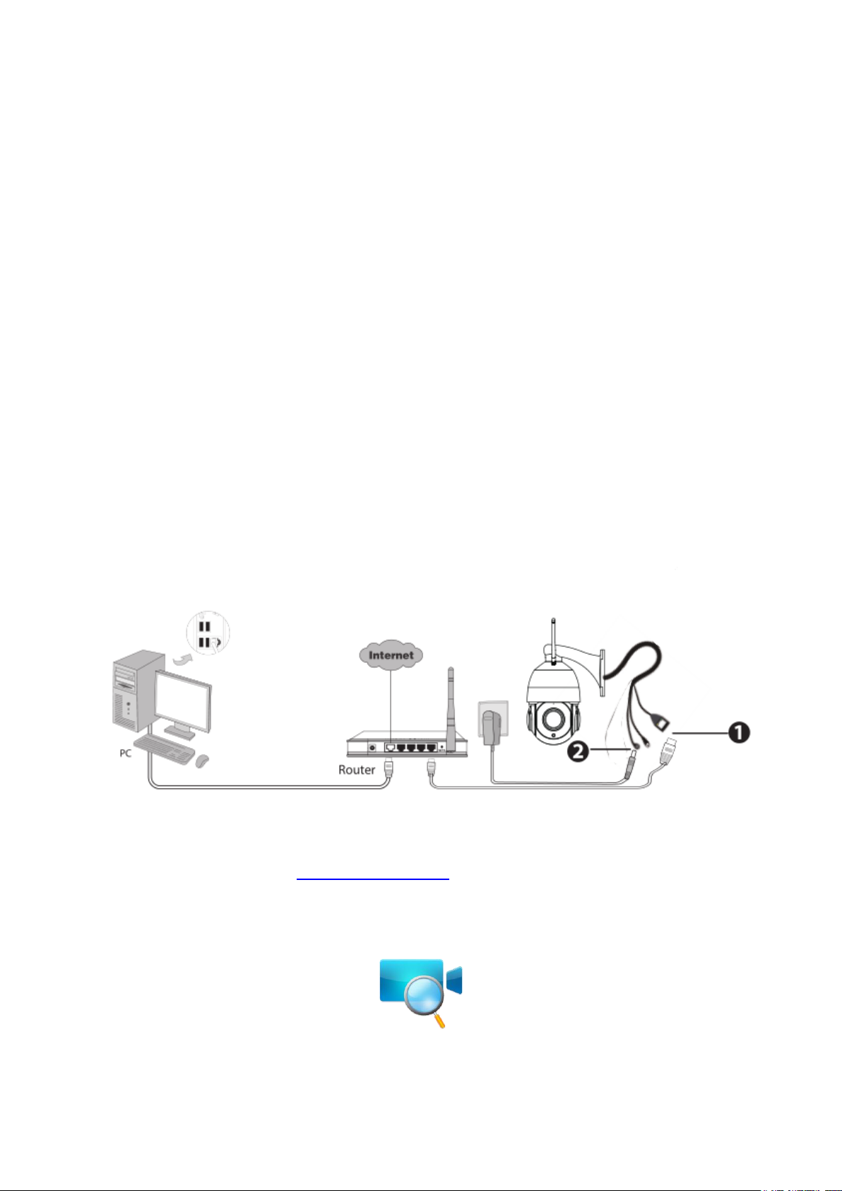
3.1 Hardware Connection & Software Installation
1. Connect the camera to the LAN network (Router or Switch) via network cable.
2. Please connect the power adapter to the camera.
3. Visit Foscam official website http://www.foscam.com , select “Support > Download Center >
Software Tools”, then you can find the “Equipment Search Tool”, download the tool to your computer,
the icon shows as below:
NOTES:
If your computer (Windows OS) supports autorun function, you can find the corresponding file in the
opened control panel.
10
3.2 Access the Camera in LAN
The camera supports HTTP and HTTPS protocols, you can access the camera in two ways.
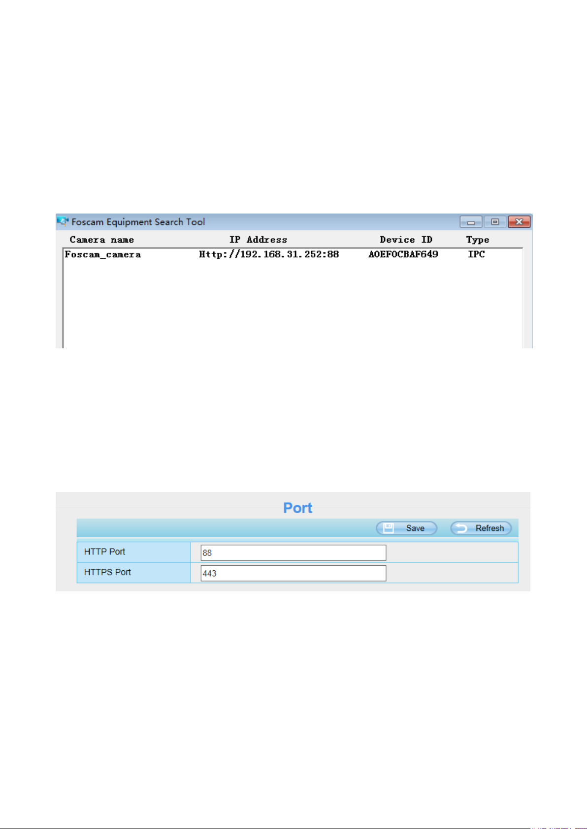
(1) Http:// LAN IP + Http Port No.
The default HTTP port NO. is 88. Double click the Search Tool icon to run, and it should find the
camera's IP address automatically after you plug in the network cable.
Double click the IP address of the camera; the camera login page should be open in your default
browser.
(2) Https:// LAN IP + Https Port no.
The default HTTPS port NO. is 443. You can use the URL to access the camera: https:// LAN IP +
HTTPS port NO.
Go to Settings > Network > Port panel, you can see and change the HTTP and HTTPS port NO.
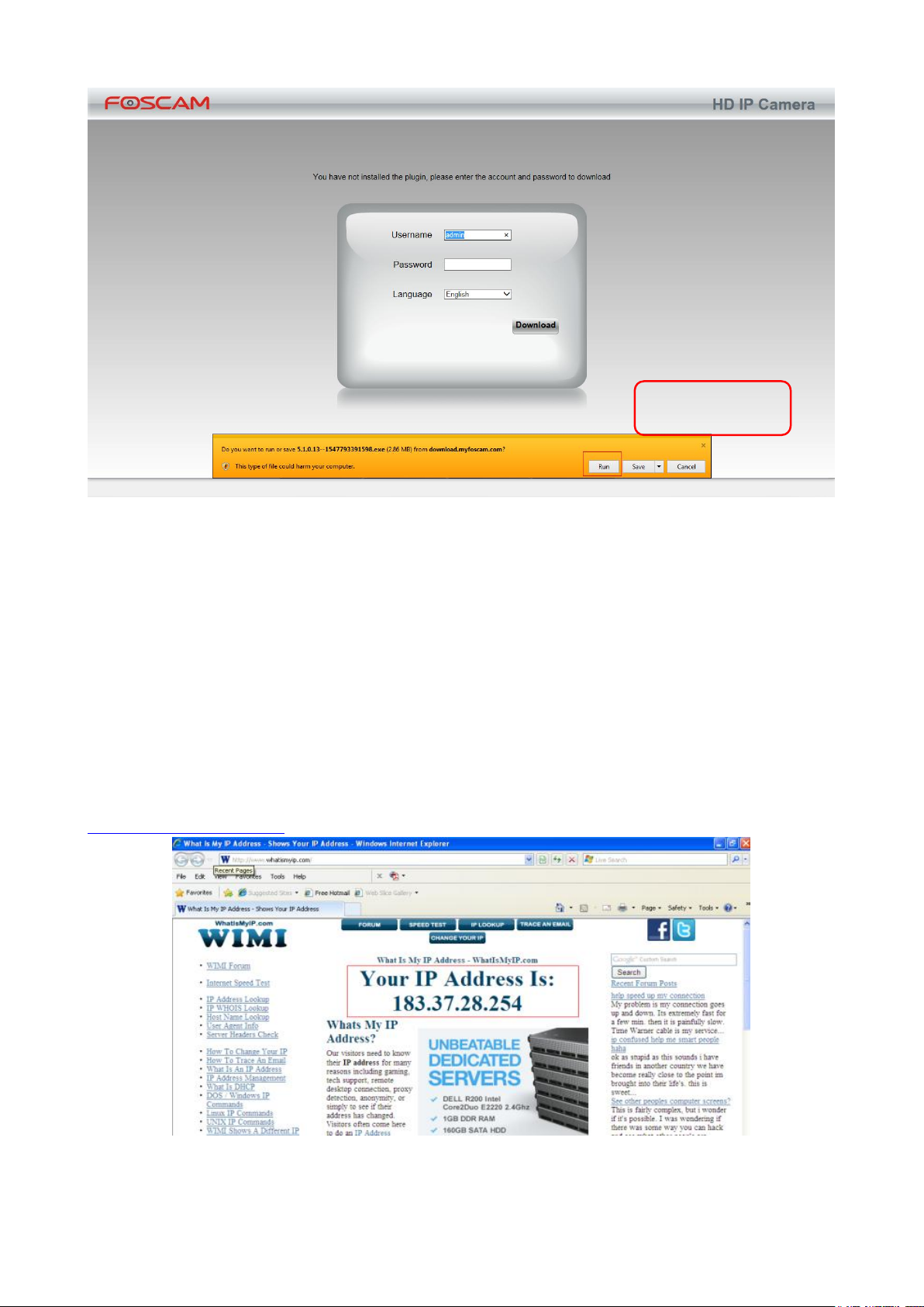
NOTE: When logging in for the first time, you will need to download and install the add-on.
11
3.3 Access the Camera in WAN
Click Run
Static IP Addresses
Users with static IP addresses after you have finished connecting the camera using the LAN IP address
and port forwarding, you can access the camera directly from Internet using the WAN IP address and
port number
How to Obtain the WAN IP address from a public website ?
To obtain your WAN IP address, enter the following URL in your browser:
http://www.whatismyip.com.The web page at this address will show you the current WAN IP.
Access your IP Camera from the Internet

12
You can access the IP Camera from the Internet (remote access). Enter the WAN IP address and port
number in your standard browser. For example, you would enter http:// 183.37.28.254:88
3.4 Using the VLC Player
This camera supports RTSP streaming, here you can view the camera using VLC player.
RTSP URL rtsp:// [user name][:password]@IP:port number/videosream
The part in the square brackets may be omitted.
user name & password:
The user name and password to access the camera. This part can be omitted.
IP: WAN or LAN IP address.
port number: If there is the RSTP port number on the Port page, you must only use RTSP port number.
otherwise, you must only use http port number.
Videostream: Here support two modes: videoMain and videoSub. When the network speed is bad, here
you had better select videoSub.
For example:
IP: 192.168.1.11
Port number: 88
User name: admin
Password: 123
Here I can enter one of the following URLs in the VLC.
1.rtsp://admin:123@192.168.1.11:88/videoMain
2.rtsp:// @192.168.1.11:88/videoMain
3.rtsp://:123@192.168.1.11:88/videoMain
4.rtsp://admin@192.168.1.11:88/videoMain
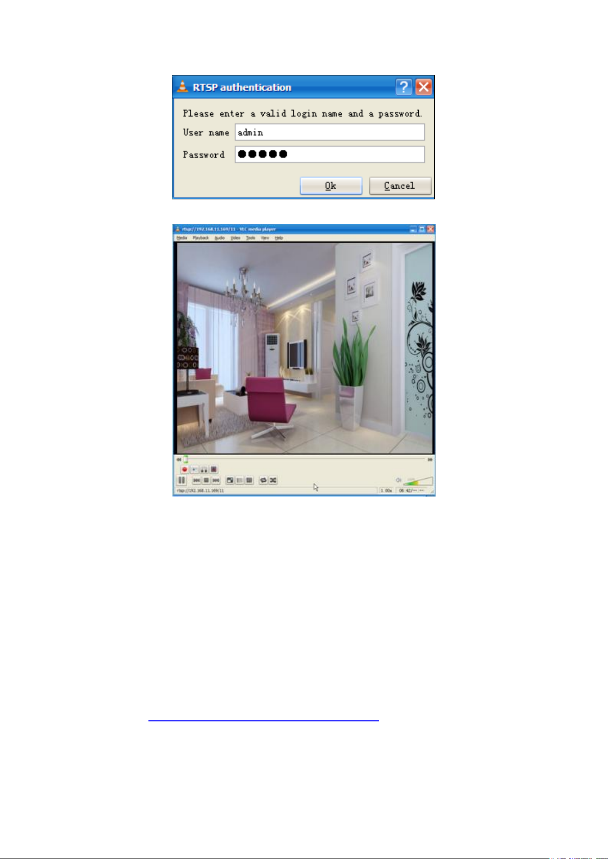
Open the VLC, and go to Media Open Network Stream option, then enter the URL into VLC.

13
Sometimes you may need to enter the user name and password again. Click OK and you can see the
14
real-time preview.
NOTE: If you modify the camera's username or password, you had better reboot the camera, or else the
new username and password cannot take effect when you enter the authentication in the VLC.
3.5 IP Camera Connection to the Server
Device supports ONVIF 2.2.1 protocol,You can easily access the NVR with ONVIF or server with ONVIF.
3.6 Surveillance Software GUI
Please refer to the 3.1 Hardware Connection & Software Installation if you install the camera for the first
time. You can start to learn about software operation after finish quick installation.
15
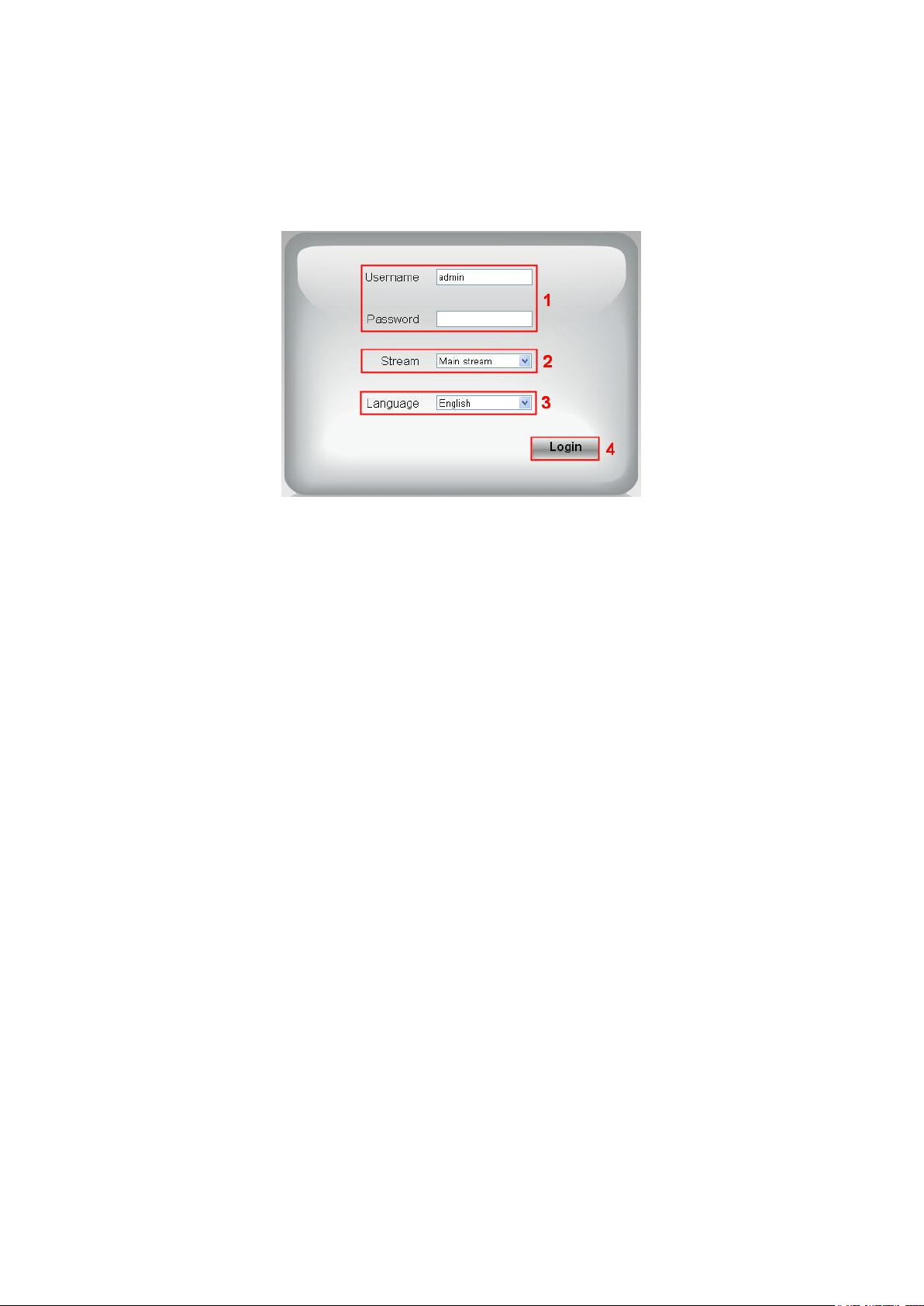
3.6.1 Login Window
Section1 Enter the Username and password
The default administrator username is admin with no password, please change the password at first
using and prevent unauthorized users login the camera.
Section2 Stream
The camera supports two stream modes: Main stream and sub stream. If you want to access the camera
form LAN, here you can select Main stream. If you want to access the camera from Internet, here we
recommend sub stream.
NOTE: When the network bandwidth is bad you'd better select Sub Stream and the video will be more
fluent.
Section3 Select the language
You can select the language you need by clicking on the language dropdown list.
Section4 login the camera
Click Login button.
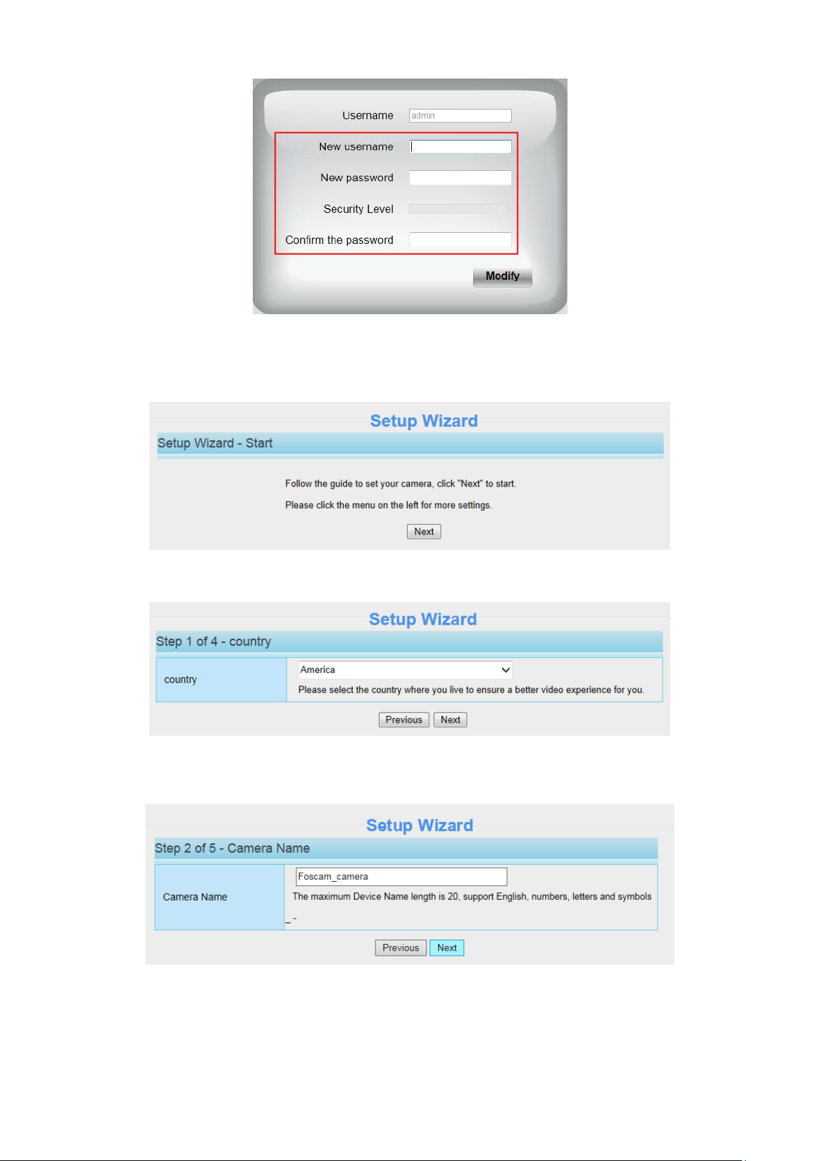
NOTE: When setting up your camera for the first time, it will request that you modify the default
username / password if both are still set to default. Input the new username and password, click Modify
to complete the modification. You will now use the new username and password to login the camera in
the future.
16
After logging in for the first time, you will go to Setup Wizard automatically. Here you can set the basic
parameters of camera, such as camera name, camera time, IP configuration.
Country: Select the country.
Device Name: You could give name for your camera.
System Time: Select the time zone you need to set the date, time, format, etc.
IP: Set IP address of the camera. You could choose to obtain an IP automatically or set the IP address
according to your needs.
17
2
5
3 4 6
7
Click Finish to finish setting.
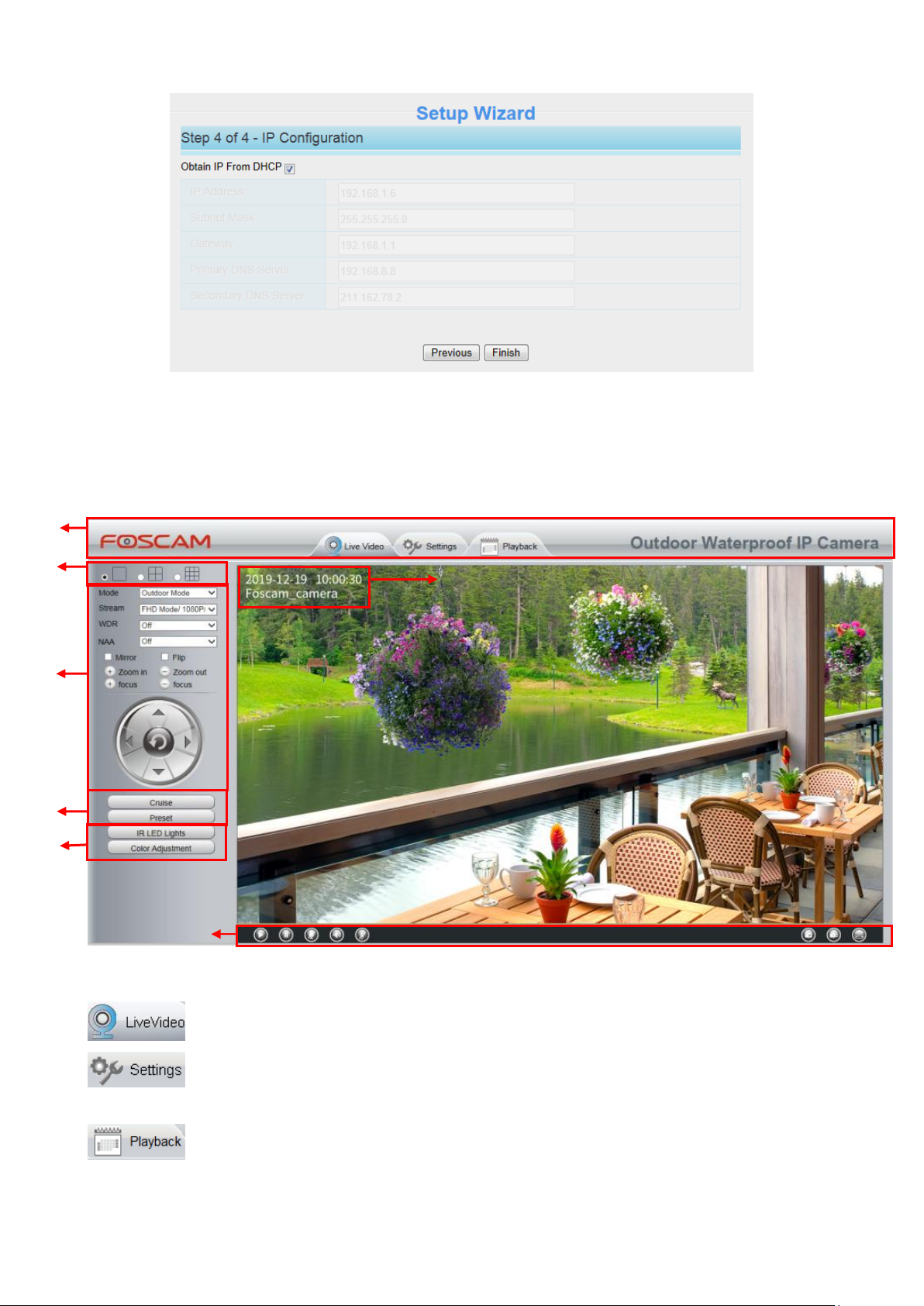
3.6.2 Surveillance Window
Section 1 Live Video / Settings Buttons / Playback
: Path to surveillance window. Click this button and back to the surveillance window.
: Path to Administrator Control Panel. Click it, and it will lead to Administrator Control Panel
and do advanced settings.
: Path to playback window, click it to search / playback the records.
18
Section 2 Multi-Device Window
The firmware inside the camera supports up to maximum of 9 cameras being monitoring at the same
time. You can add other cameras in multi-camera panel.
Section 3 Mode / Stream / WDR / NAA / Mirror / Flip Buttons / Zoom in / out
Mode
1) 50Hz ---------Indoor surveillance (Region: Europe, China)
2) 60Hz ---------Indoor surveillance (Region: USA, Canada)
3) Outdoor Mode------Outdoor surveillance
Stream
The default stream supports multiple modes, For example: HD Mode / 1080P / 25fps / 4M meanings:
Stream type / Resolution / Maximum frame rate / Bit rate. (Different models support different specific
mode. )
1) Stream type no. Identify the stream type.
2) Resolution
The bigger the resolution, the better of the image quality is. If you are accessing the camera via internet
and want to get more fluent video streaming, please select resolution VGA.
3) Maximum frame rate
The maximum frame rate is 30 fps. You should lower frame rate when the bandwidth is limited. Normally,
when the frame rate above 15, you can achieve fluently video. The maximum frame rate for each model
is different.
4) Bit Rate
Generally speaking, the larger the bit rate is, the clearer video will become. But the bit rate configuration
should combine well with the network bandwidth. When the bandwidth is very narrow, and bit rate is
large, that will lead to video cannot play well.
You can reset the stream type on Settings > Video > Video Settings panel.
19
1
2 3 4
WDR: WDR stands for High Dynamic Range. It usually refers to the method of capturing images having
"greater dynamic range between the lightest and darkest areas of an image than current standard digital
imaging methods or photographic methods". You can select On from the dropdown list under sunlight or
with bright background.
NAA: NAA (Network Auto-Adaptability) can make IP Camera changing the real-time rate to adapt
different network conditions, which can supply better preview experience. It is OFF as default.
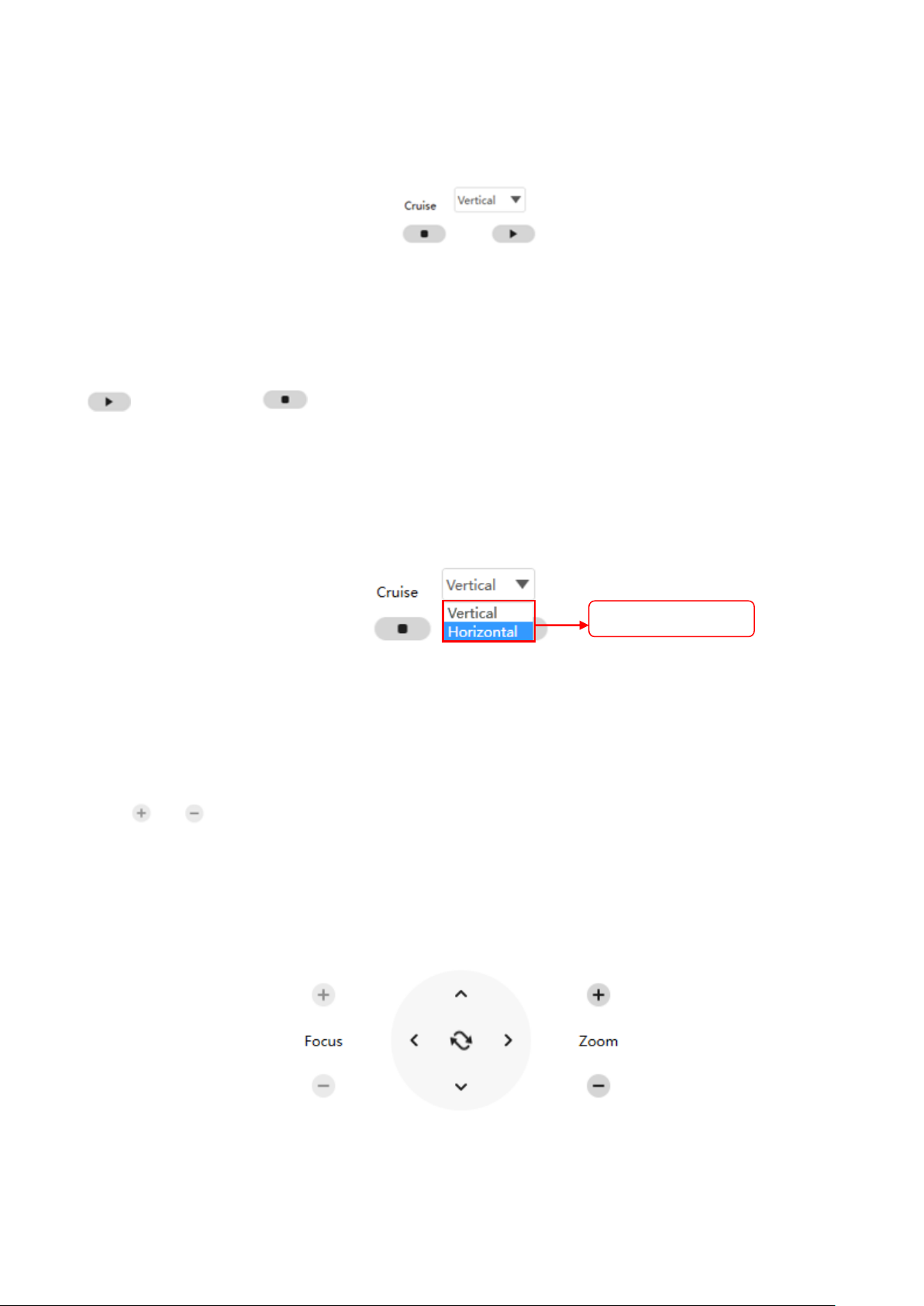
Zoom In or Zoom Out
Device Support 4x zoom feature, click or ,The focal length of the camera lens will be larger or
shrink, you can adjust the focus distance to the target object size, access to high-definition screen.
Zoom Control
Zoom in the camera‟s lens.
Zoom out the camera‟ lens.
You can adjust the speed of the lens‟ zoom in Settings--PTZ--Pan & Tilt Speed--Zoom speed panel.
Pan/Tilt Control
1----- Up control button, 2-----Down control button,
3------Left control button, 4------Right control button
Click this button and go to center
20
Select one of these.
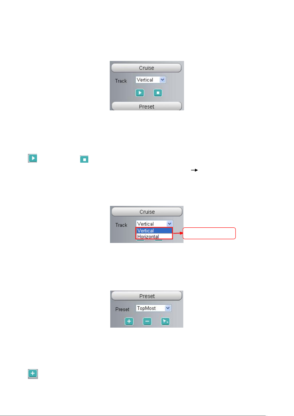
Section 4 Cruise / Preset settings
Cruise Settings
The default cruise tracks have two types: Vertical and Horizontal.
Vertical: The camera will rotate from up to down.
Horizontal: The camera will rotate from left to right.
: Start cruise. : Stop cruise.
If you want to define or change the cruise trace, please go to Settings PTZ Preset Settings panel.
How to do cruise?
Firstly: Select one track in the track dropdown list.
Secondly: Click Start cruise button, the camera will cruise following the predefined path.
Thirdly: Click stop button and finish cruising.
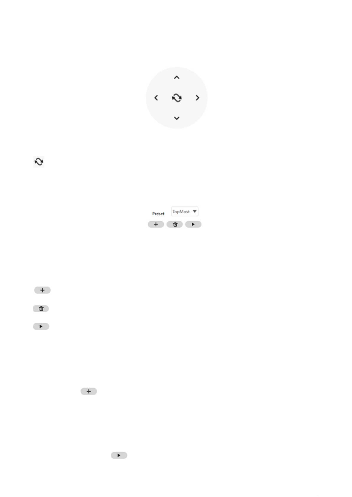
Preset settings
IPCam supports 16 preset positions, which is considered enough for DIY home & small business
surveillance market
The default preset position is Topmost, Bottom most, Left most, right most, you can add other preset
positions.
Add Click this icon to save the position you need the camera to remember
21
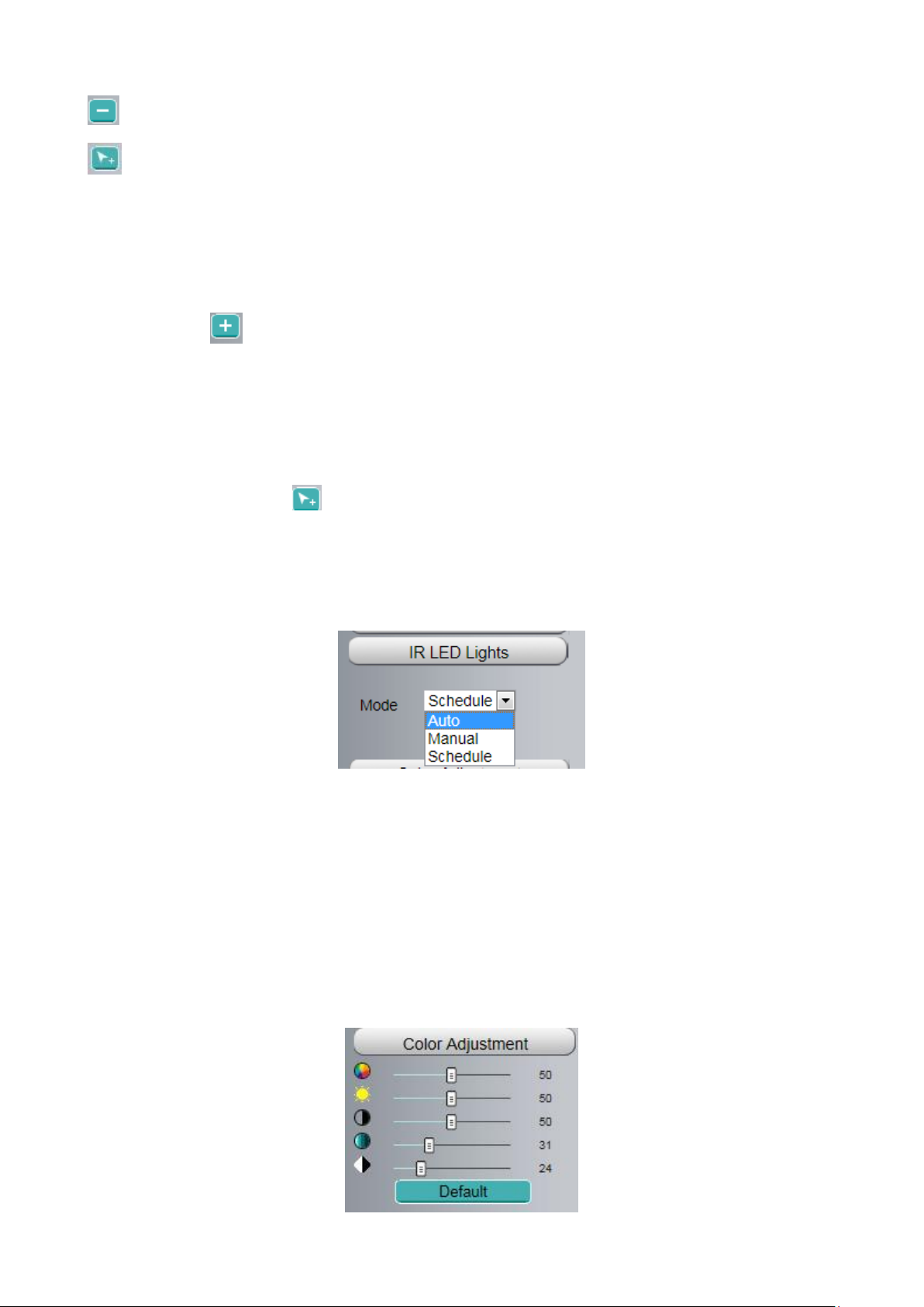
Delete Select one preset position and click this button to delete it.
GO Select one preset position in the preset drop-down list and click Go to make the camera
move the preset position
How to do preset position?
Firstly, move the camera and stop at a desired place where you want make preset position.
Secondly, click button and enter a descriptive name for the preset position. The preset position
cannot contain special characters. Then click OK to save it. If you want to reset the preset position, click
Cancel.
After that, you can move the camera and stop at another place, and set another preset position. You can
do all the 16 preset positions with this method.
If you want to see one preset position you have set, only select the preset position name from the preset
drop-down list, and click go button, the camera will go to the preset position.
Section 5 IR LED Lights / Color Adjustment
IR LED Lights
Click Infra led and there are three modes to adjust the infrared led: Auto, Manual and Schedule.
Auto: Select it and the camera will adjust the infra led (on or off) automatically.
Manual: Select it and turn off the infra led manually.
Schedule: Select it and the IR led light will be off at the schedule period. If you want to define or change
the IR led lights schedule time, please go to Settings > Video > IR LED Schedule page.
Color Adjustment
In this page, you can tune Hue, Brightness, Contrast, Saturation, and Sharpness to get higher quality.
22
6
7
8
1
2 3 4
5
Section 6 OSD
If you have added time and camera name in the video, you can see it in the live window.
Go to Settings > Basic settings > Camera name panel, and you can change another device name.
The default device name is anonymous.
Go to Settings > Basic Settings > Camera time panel and adjust the device time.
Go to Settings > Video > On Screen Display panel, you can add or no add OSD.
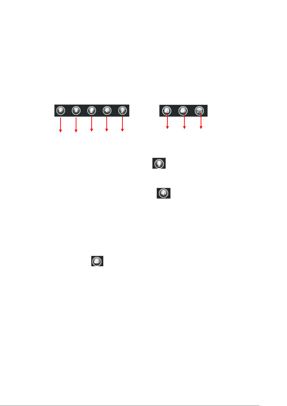
Section 7 Play / Stop / Snap / Record / Full screen button
1------Play Click it to play the video of the camera
2------Stop Click it to stop the video of the camera
3------ Talk Click the button and the icon will become to , then talk to the microphone that
connected with PC, people around the camera can hear your voice if the camera has connected with
audio output device. Click the icon again and stop talking.
4------ Audio Click the button and the icon will become to , you can hear the sound around the
camera if the camera has connected with other audio input device through the Audio Input port of the
camera, Click the icon again and stop audio.
5----- Volume click it to open the volume control.
6----- Snap Click it to make snapshot and it pop up a window which picture you snapshot, right click in
the window and save the picture to anywhere you want.
7----- Record Click the icon and the camera start recording, you can see a green dot in the live
window. Click again and stop recording. The default storage path is C:\IPCamRecord. You can change
the storage path: Go to Settings > Record > Storage Location panel.
8------Full Screen Click it to make full-screen, or you can double click the surveillance screen to make
full-screen. Double click again and exit full-screen.
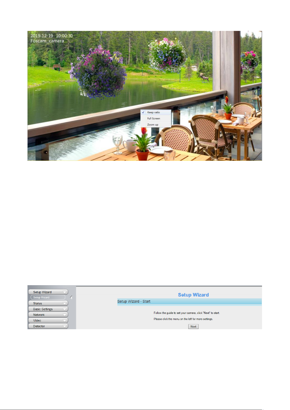
Onscreen Mouse Control
Right click the mouse and you can full screen and Zoom up.
23
Full Screen: Select it and Click it to make full-screen, press ESC and exit full-screen.
Zoom Up / Down: Click it and the live view will be digital zoomed up, then click Zoom Down and the live
view back to original size.
NOTE: For Mac OS, the plugin cannot support Onscreen Mouse function, so you cannot allow to use it.
3.7 Advanced Camera Settings
Click the button Settings, goes to Administrator Control Panel to make advanced camera settings.
3.7.1 Setup Wizard
After logging in for the first time, you will go to "Setup Wizard" automatically. Here you can set the basic
parameters of camera, such as the camera name, camera time, IP configuration and so on.
3.7.2 Status
Status contains four columns: Device Information, Device Status, Session Status and Log, it will show
you various information about your camera.
24
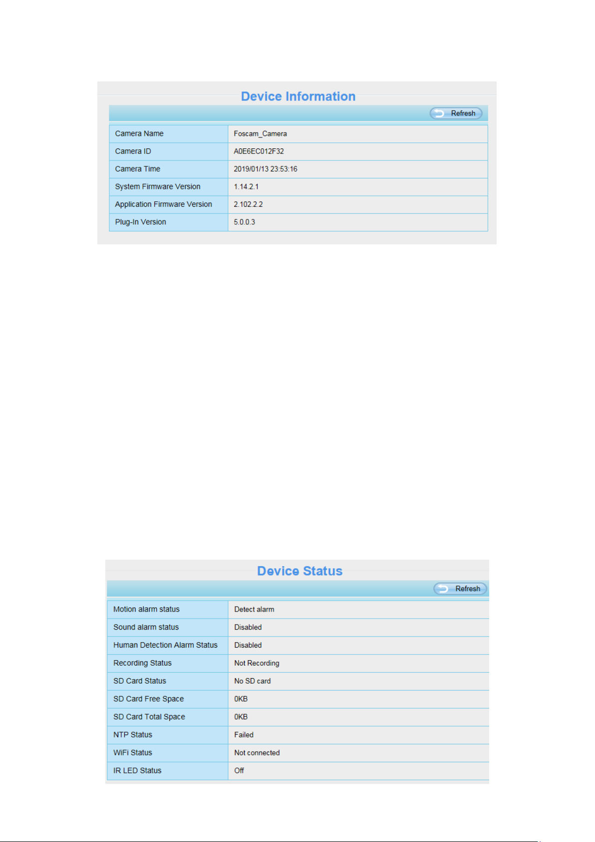
3.7.2.1 Device Information
Camera Name: The Device Name is a unique name that you can give to your device to help you identify
it. Click Basic Settings and go to Device Name panel where you can change your camera name. The
default device name is anonymous.
Camera ID: Display the MAC address of your camera. For example Device ID is A0E6EC012F32, the
same MAC ID sticker is found at the bottom of the camera.
Camera Time: The system time of the device. Click Basic Settings and go to Camera Time panel and
adjust the time.
System Firmware Version: Display the System Firmware version of your camera.
Application Firmware Version: Display the application firmware version of your camera.
Plug-In Version: Display the plug-in version of your camera
3.7.2.2 Device Status
On this page you can see device status such as Alarm status, NTP status, IR LED Status and so on.
25
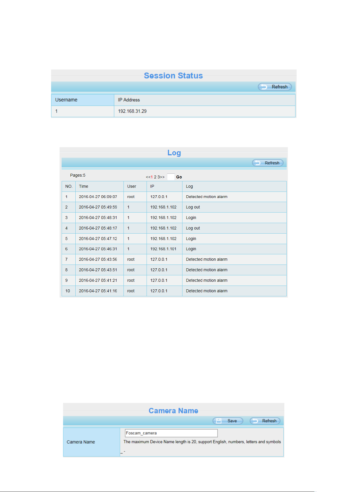
3.7.2.3 Session Status
Session status will display who and which IP is visiting the camera now.
3.7.2.4 Log
The log record shows who and which IP address accessed or logout the camera and when.
Reboot the camera and clear the log records.
3.7.3 Basic Settings
This section allows you to configure your Camera Name, Camera Time, Mail, User Accounts and
Multi-Device.
3.7.3.1 Camera Name
Default alias is Foscam_camera. You can define a name for your camera here such as apple. Click Save
to save your changes. The alias name cannot contain special characters.
26
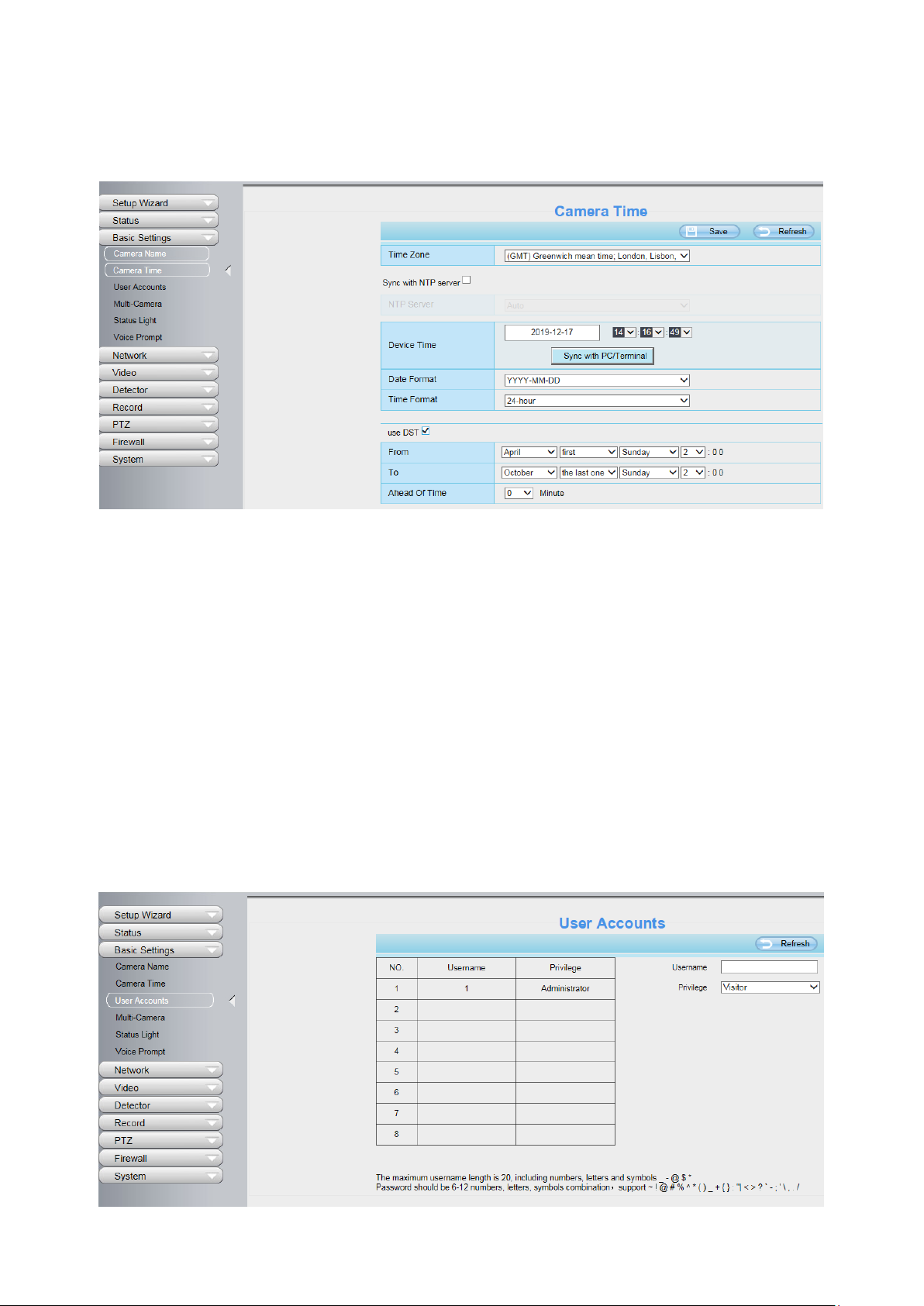
3.7.3.2 Camera Time
This section allows you to configure the settings of the internal system clocks for your camera.
Time Zone: Select the time zone for your region from the drop-down menu.
Sync with NTP server: Network Time Protocol will synchronize your camera with an Internet time server.
Choose the one that is closest to your camera.
Sync with PC/Terminal: Select this option to synchronize the date and time of the Network Camera with
your computer.
Manually: The administrator can enter the date and time manually. Please select the date and time
format.
use DST: Select the use DST, then select the daylight saving time from the drop-down menu.
Click Save button to submit your settings.
NOTE: If the power supply of camera is disconnect, you need set the camera's time again.
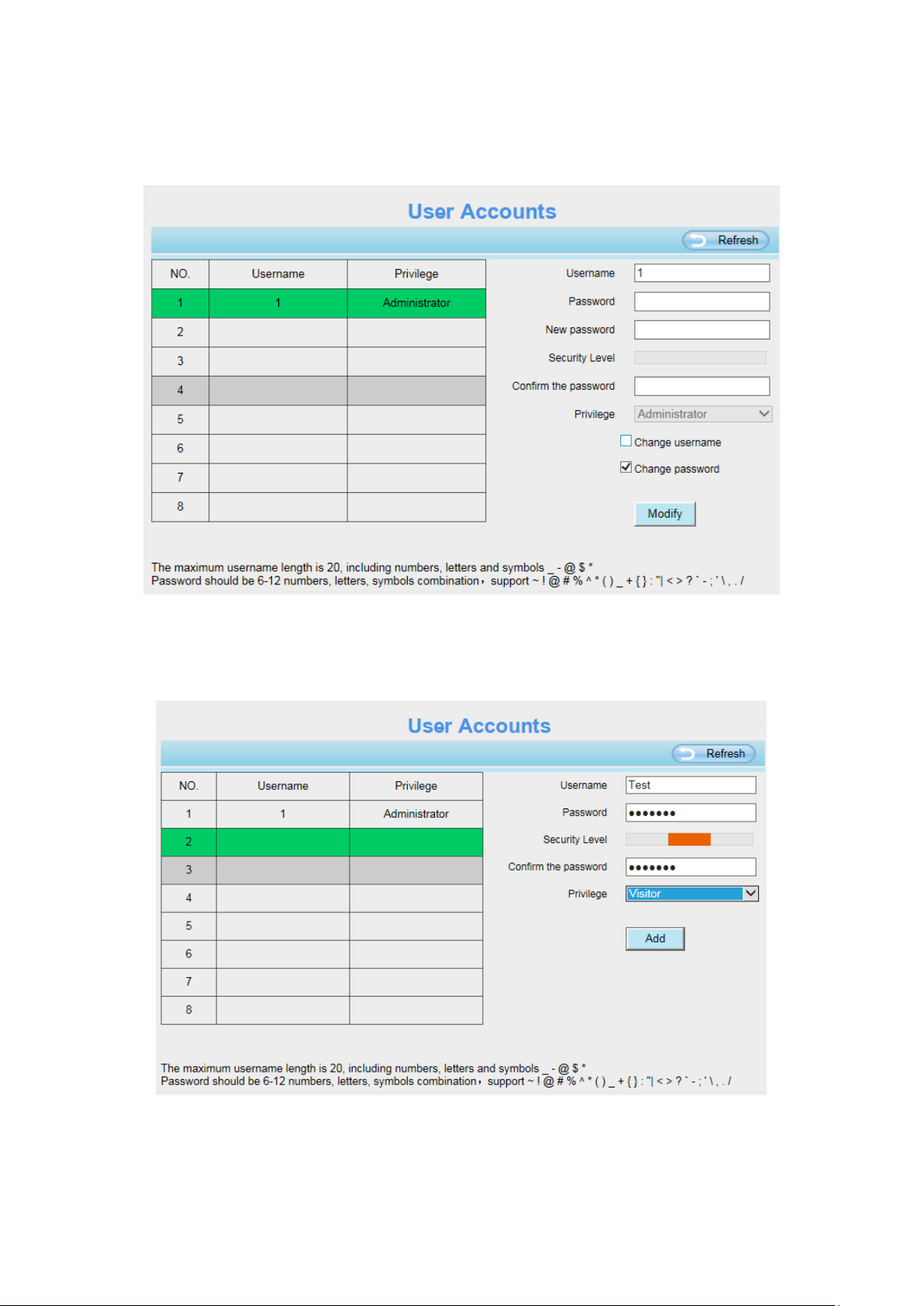
3.7.3.3 User Accounts
Here you can create users and set privilege, visitor, operator or administrator. The default
administrator user accounts are admin with a blank password.
27
How to change the password?
Firstly, select the account which you want to change the password, then select Change password,
enter the old password and the new password, lastly click modify to take effect.
How to add account ?
Select one blank column, then enter the new user name, password and privilege, last click Add to take
effect. You can see the new added account on the Account list.
28
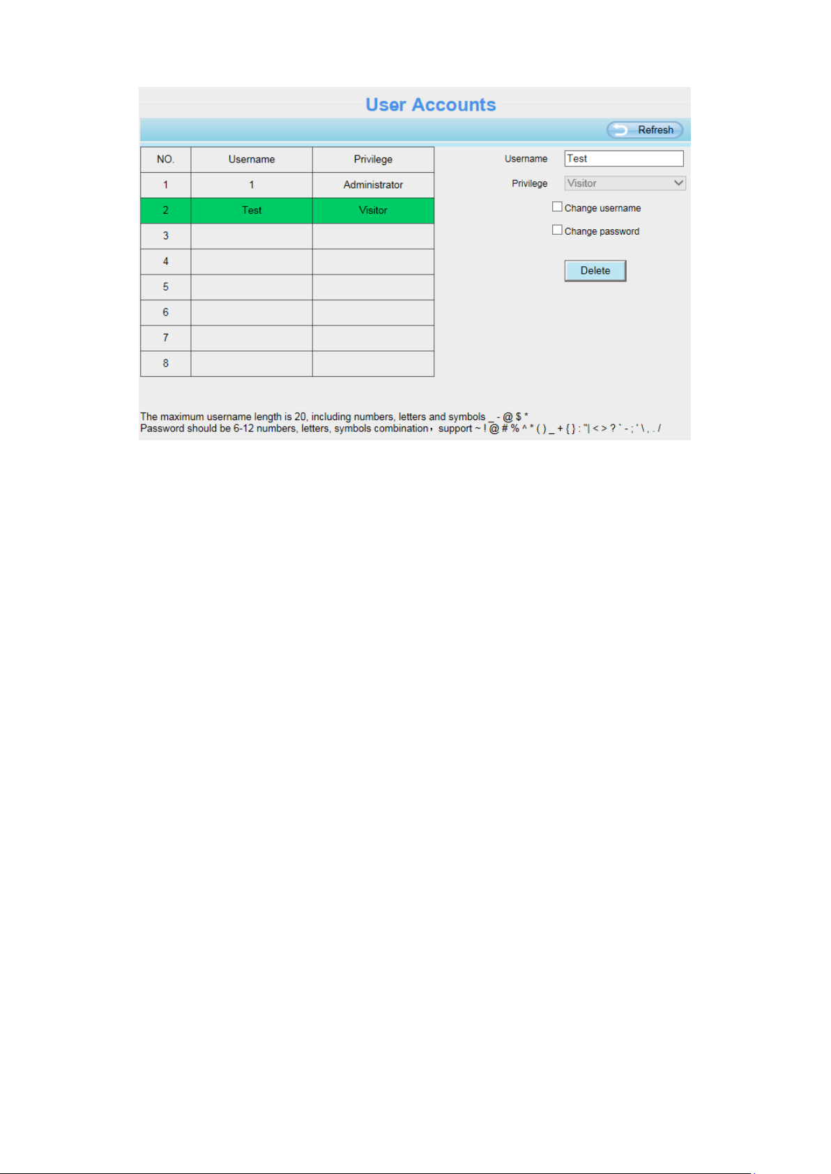
Delete: Select the account which you want to delete, then click Delete button to take effect.
NOTE: The default administrator account cannot be deleted, but you can add other administrator users.
3.7.3.4 Multi-Camera
If you want to view multi-surveillance screens on one window, you need to login one camera, and set it
as the main device, and do Multi-Device Settings, add other cameras to the first one camera. Before you
do multi-cams settings, you need to assign different port such as 81, 82, 83, 84, 85, 86, 87, 88 to the
cameras if there is 8 cameras installed.
The firmware within the camera can support a maximum of 9 devices monitoring all at the same time.
This page you can both add FOSCAM MJPEG and H.264 series cameras to the first camera and view
multi-surveillance screen on one window.
Add Cameras on LAN
In Multi-Device Settings page, you can see all devices searched in LAN. The 1st Device is the default
one. You can add more cameras in the list in LAN for monitoring. The camera's software supports up to 9
IP Cameras online simultaneously. Click The 2nd Device and click the item in the Device List in LAN,
the Alias, Host and Http Port will be filled in the boxes below automatically. Enter the correct username
and password then click Add. Add more cameras in the same way.

29
1 Click it, camera model, alias,
host and HTTP Port will be filled
in the following boxes
automatically.
2 Enter the User name and
password of the 2nd camera.
3 Click Add to take effect.
Camera Model: Our Company produces two series cameras: MJPEG and H.264. Here will show you
which series the camera belongs to.
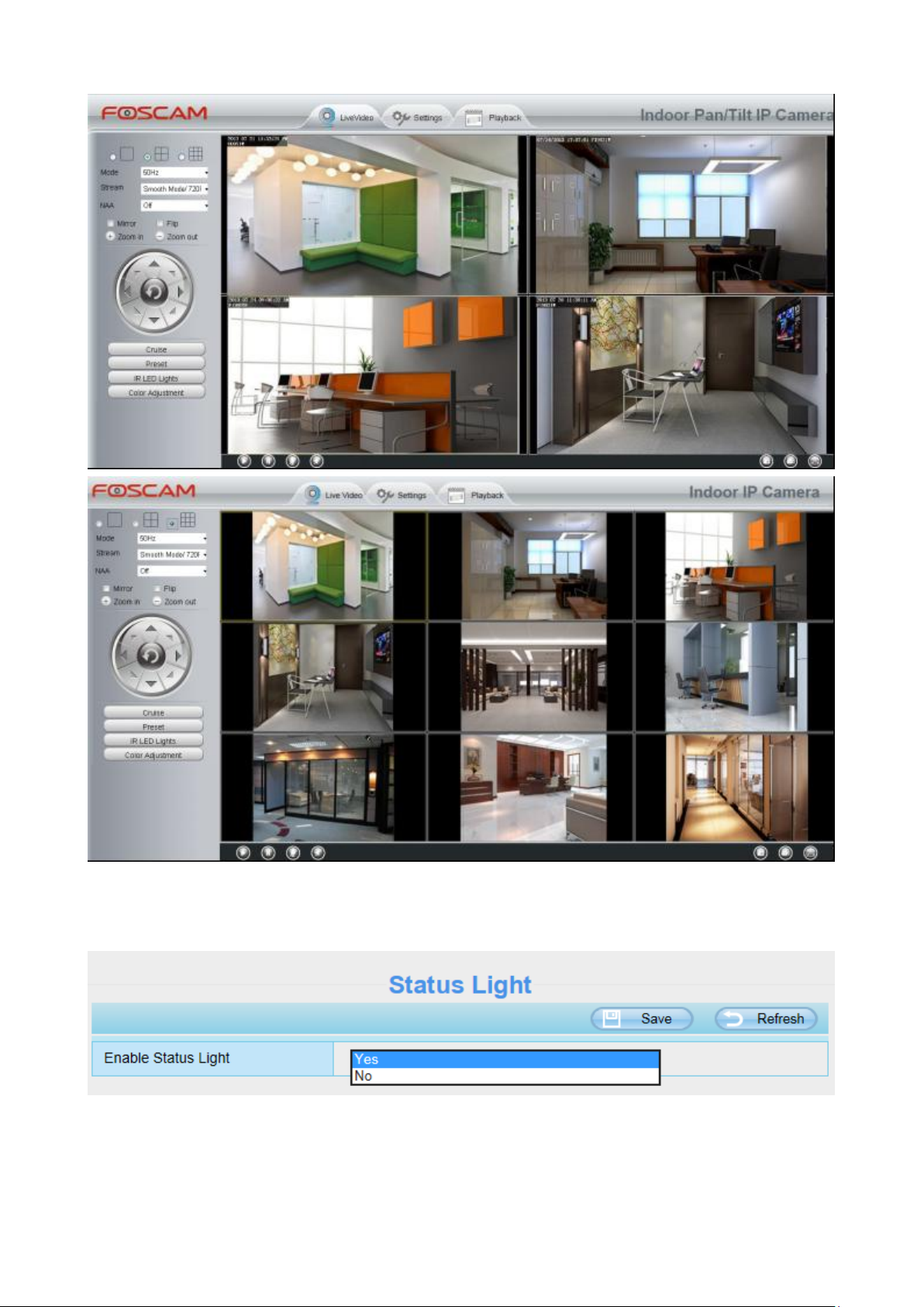
Back to Surveillance Windows, and click Four Windows option, you will see four cameras you added.
30
3.7.3.5 Status Light
You can enable or disable status light.
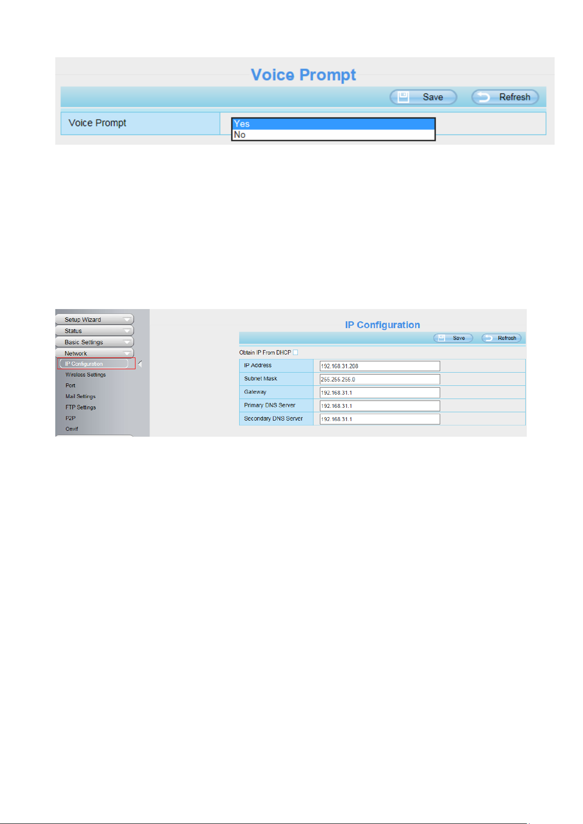
3.7.3.6 Voice Prompt
On this page, you can enable or disable voice prompt. Select “Yes” to enable or select “No” to disable.
If select ”Yes”, you can hear the voice prompt after connect the audio output device.
31
3.7.4 Network
This section will allow you to configure your camera's IP, Port, Mail Settings and FTP Settings and so on.
3.7.4.1 IP Configuration
If you want to set a static IP for the camera, please go to IP Configuration page. Keep the camera in the
same subnet of your router or computer.
Changing settings here is the same as using the Equipment Search Tool.
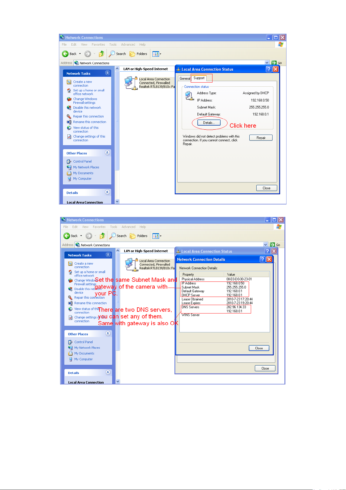
It is recommended that you use the subnet mask, gateway and DNS server from your locally attached
PC. If you don't know the subnet mask, gateway and DNS server, you can check your computer's local
area connection as follows:
Control Panel > Network Connections > Local Area Connections > Choose Support > Details.
32
If you don't know the DNS server, you can use the same settings as the Default Gateway.
3.7.4.2 Wireless Settings
Step 1: Choose “Settings” on the top of the camera interface, and go to the “Network” panel on the
left side of the screen, then click “Wireless Settings.”
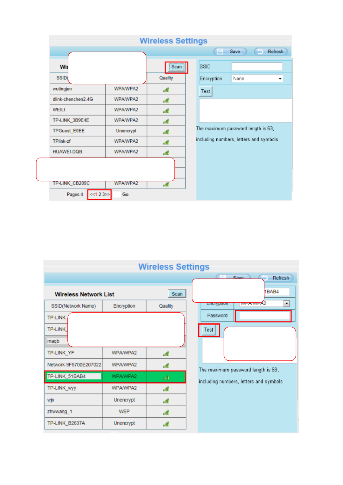
Click the Scan button and the camera will detect all wireless networks around the area. It should also
display your router in the list.
33
Click the Page number to see other wireless
networks devices if there are more than 10.
Click the Scan button
to search for wireless
networks.
1 Click the SSID of your router and
the relevant information will be filled
in the fields automatically.
2 Enter the password
of your router.
3 Click Test to check
if the password is
correct or not.
Step 2: Click the SSID (name of your router) in the list, the corresponding information related to your
network, such as the name and the encryption, will be filled into the relevant fields automatically.
You will only need to fill in the password of your network. Make sure that the SSID, Encryption and the
password you filled in are exactly the same for your router.
Step 3: Please click on the Save button after all settings have been entered and disconnect the network
34
cable. Never shut down the power of the camera until the IP camera is able to connect to the wireless
Select which camera
you’d like to change the
port for, and right click.
network.
The LAN IP address will disappear on the window of Equipment Search Tool when the camera is
configuring a wireless connection. Wait about 1 minute, the camera should obtain a wireless connection,
and the LAN IP of the camera will show again on the window of the Equipment Search Tool. The IP
address may have changed after the camera receives a wireless connection; we recommend setting a
static local IP address if this IP address changes by right clicking the camera in Equipment Search Tool,
setting a static IP, and pushing OK.
Congratulations! You have set up the wireless connection of the camera successfully.
NOTE :
If you fail to make a wireless connection, please refer to your seller or contact us directly for assistance.
3.7.4.3 Port
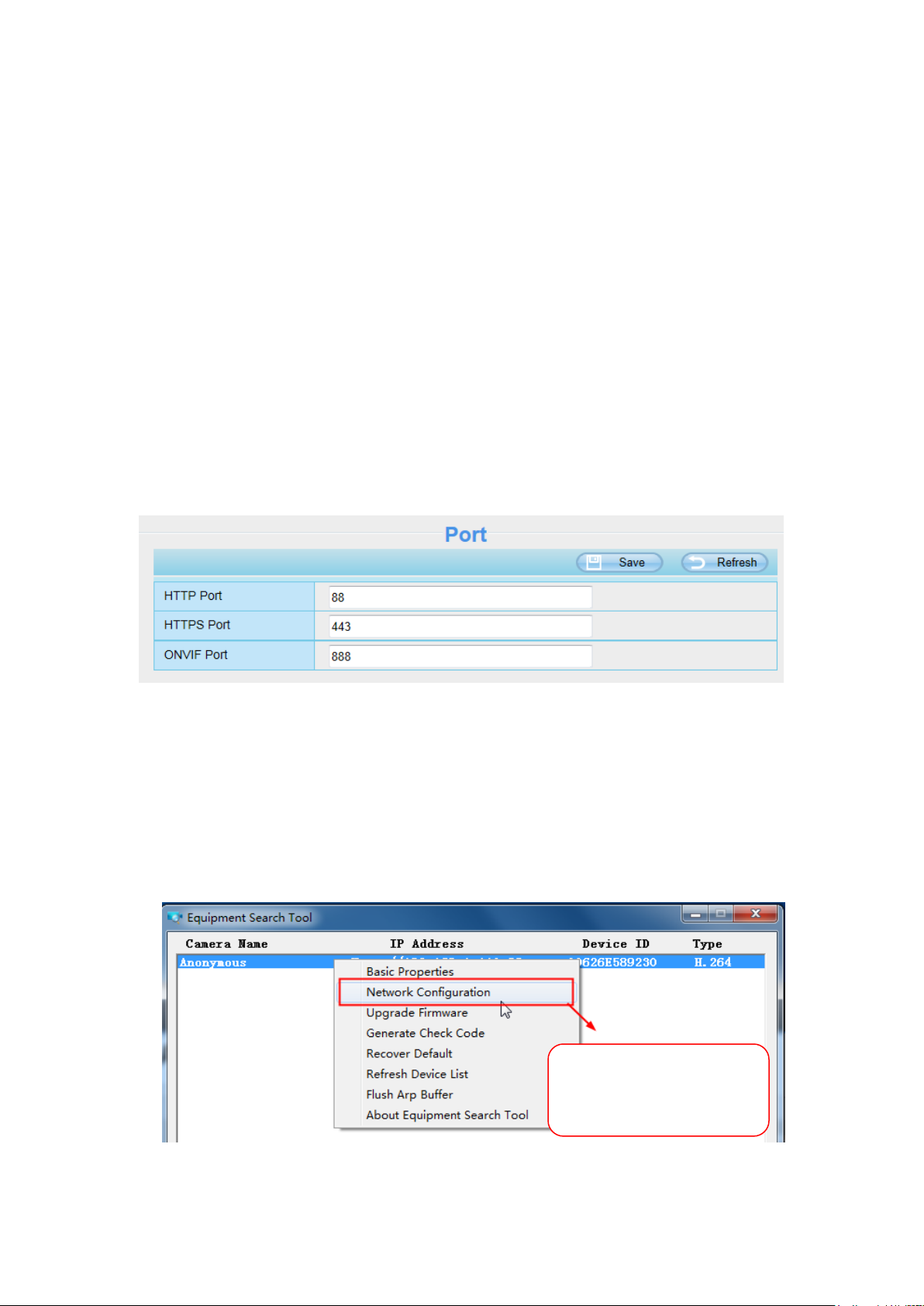
This camera supports HTTP Port. HTTP Port is used to access the camera remotely. If you want to
access the camera and view the video, the HTTP Port must both be configured correctly.
HTTP port: By default, the HTTP is set to 88. Also, they can be assigned with another port number
between 1 and 65535. But make sure they can not be conflict with other existing ports like 25, 21.
Another way to change the HTTP port NO.
Step 1: Open the Equipment Search Tool, select the camera you would like to change the port of, right
click on the IP address, and click on ”Network Configuration”, this brings up the network configuration
box as flowing figures.
35
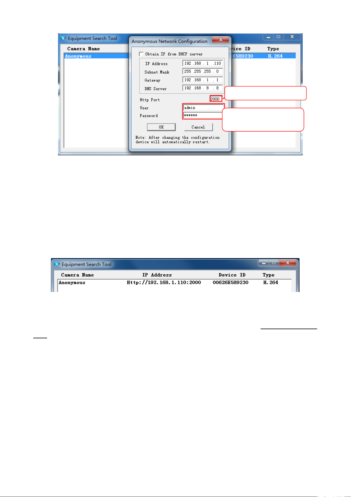
Modify the Http Port.
Enter the Username and
password, click OK.
Step 2: Enter the username and password of the Administrator (default username is admin with a blank
password), and click “OK” to apply changes.
Step 3: Wait around 10 seconds, you‟ll see that the camera‟s LAN IP address has changed. In our
example it was changed to 2000, so we see http://192.168.1.110:2000 in Equipment Search Tool. Also,
the LAN IP address is now fixed at a static IP address of http://192.168.1.110:2000. This IP address will
not change even if the camera is powered off and back on, the camera will remain on this LAN IP
address. This is very important that a static LAN IP address is set, or you may have problems later with
remote access and seeing the camera remotely if the camera loses power and reconnects on a different
LAN IP address. Make sure you set a static LAN IP address!
If the camera cannot be accessed, please make sure the port forwarding is succeed.
HTTPS port: The default port is 443. You can use the url to access the camera: https:// IP + HTTPS
port.
ONVIF port: By default, the ONVIF port is set to 888. Also, they can be assigned with another port
number between 1 and 65535(except 0 and 65534). But make sure they can not be conflict with other
existing ports.
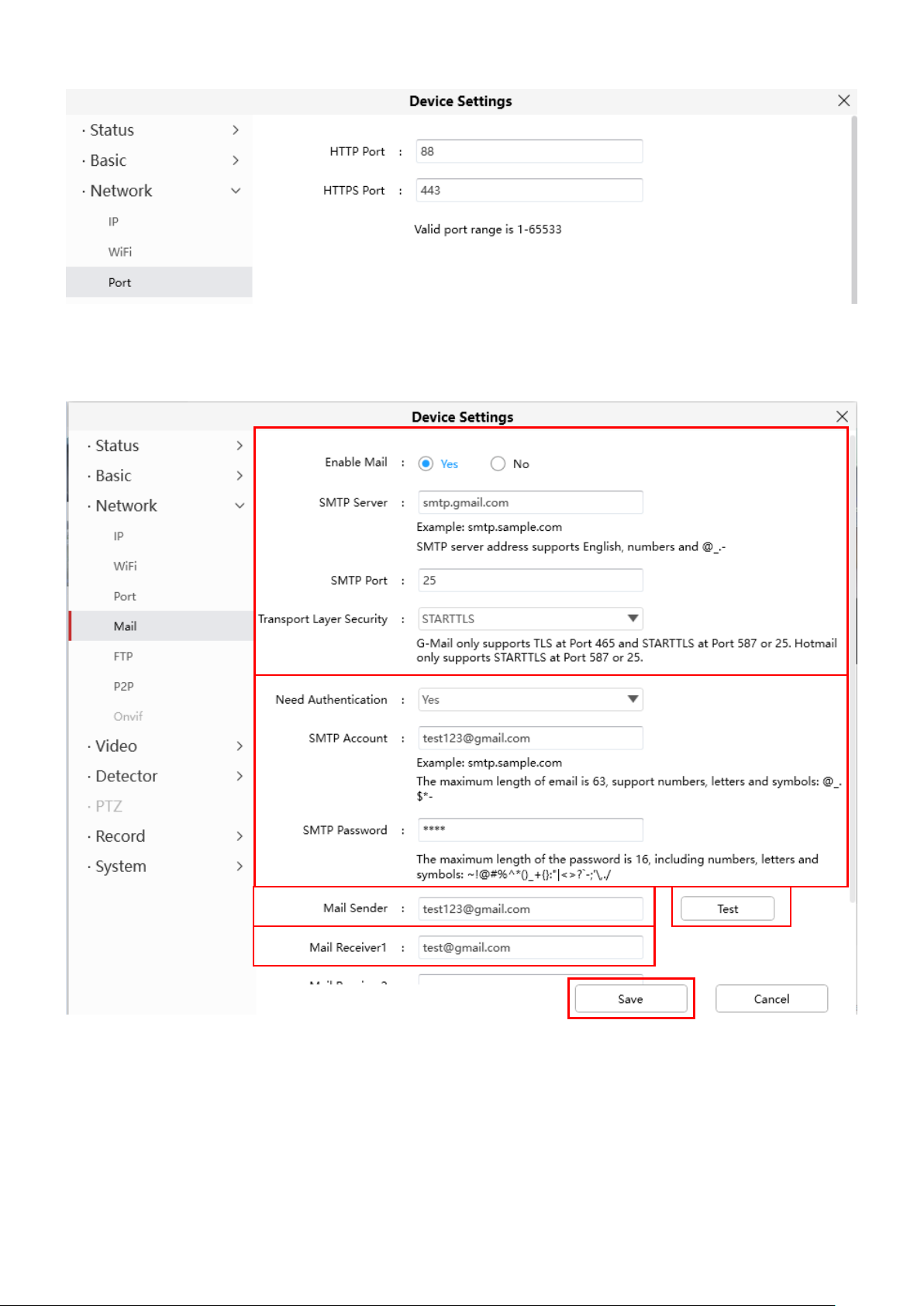
3.7.4.4 Mail Settings
If you want the camera to send emails when motion has been detected, here Mail will need to be
configured.

36
1
2
3
4 5 6
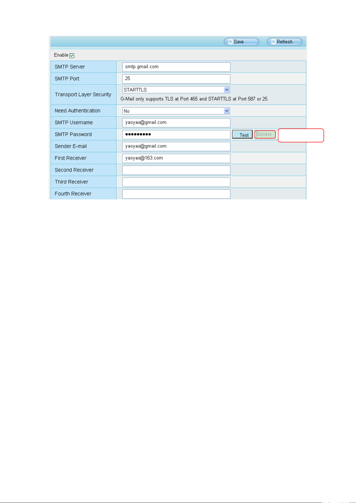
1----- SMTP Server / Port / Transport Layer Security Enter SMTP server for sender. SMTP port is
usually set as 25. Some SMTP servers have their own port, such as 587 or 465, and Transport Layer
Security usually is None. If you use Gmail, Transport Layer Security must be set to TLS or STARTTLS
and SMTP Port must be set to 465 or 25 or 587, which port you choose should be decided by which
Transport Layer Security you select.
2-----SMTP Username / password ID account and password of the sender email address
3----- Sender E-mail Mailbox for sender must support SMTP
4----- Receiver Mailbox for receiver need not support SMTP, you can set 4 receivers
5----- Save Click Save to take effect
6----- Test Click Test to see if Mail has been successfully configured.
Click Test to see if Mail has been successfully configured.
37
Test result.
If the test success, you can see the Success behind the Test, at the same time the receivers will receive
a test mail.
If the test fails with one of the following errors after clicking Test, verify that the information you entered is
correct and again select Test .
1) Cannot connect to the server.
2) Network Error. Please try later.
3) Server Error.
4) Incorrect user or password.
5) The sender is denied by the server. Maybe the server need to authenticate the user, please check it
and try again.
6) The receiver is denied by the server. Maybe because of the anti-spam privacy of the server.
7) The message is denied by the server. Maybe because of the anti-spam privacy of the server.
8) The server does not support the authentication mode used by the device.
3.7.4.5 FTP Settings
If you want to upload record images to your FTP server,you can set FTP Settings.

38
FTP server: If your FTP server is located on the LAN, you can set as Figure as above.
If you have an FTP server which you can access on the internet, you can set as below.
Port: Default is port 21. If changed, external FTP client program must change the server connection port
accordingly.
FTP Mode: Here supports two modes: PORT and PASV.
Username / password: The FTP account and password.
Click Save to take effect.
Click Test to see if FTP has been successfully configured.
39
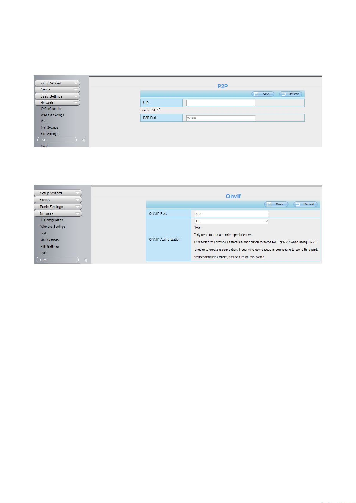
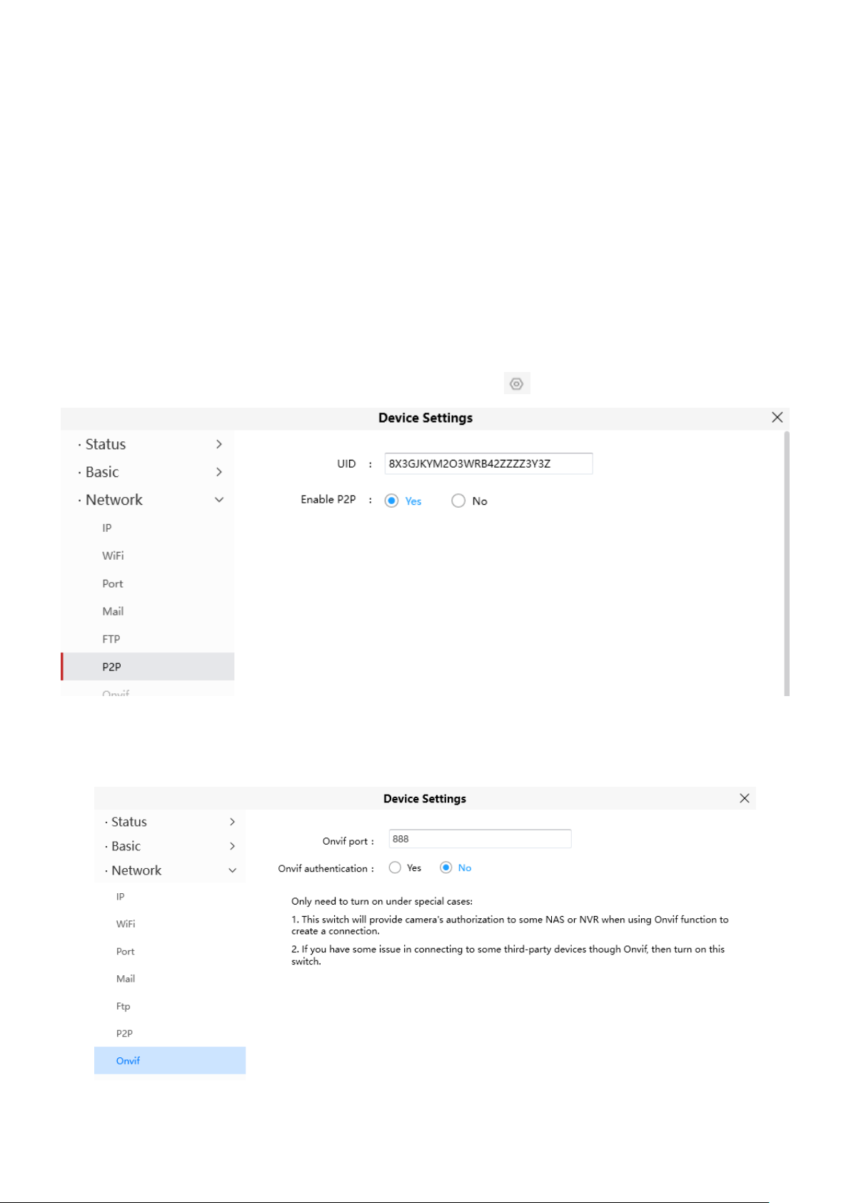
3.7.4.6 P2P
Access the camera by smart phone (Android or iOS operating system), please refer to the Quick Setup
Guide.
First of all, you need to open the P2P function of the camera at Settings > Network > P2P.
3.7.4.7 Onvif
By default, the ONVIF port is set to 888. Also, they can be assigned with another port number between 1
and 65535(except 0 and 65534). But make sure they can not be conflict with other existing ports.
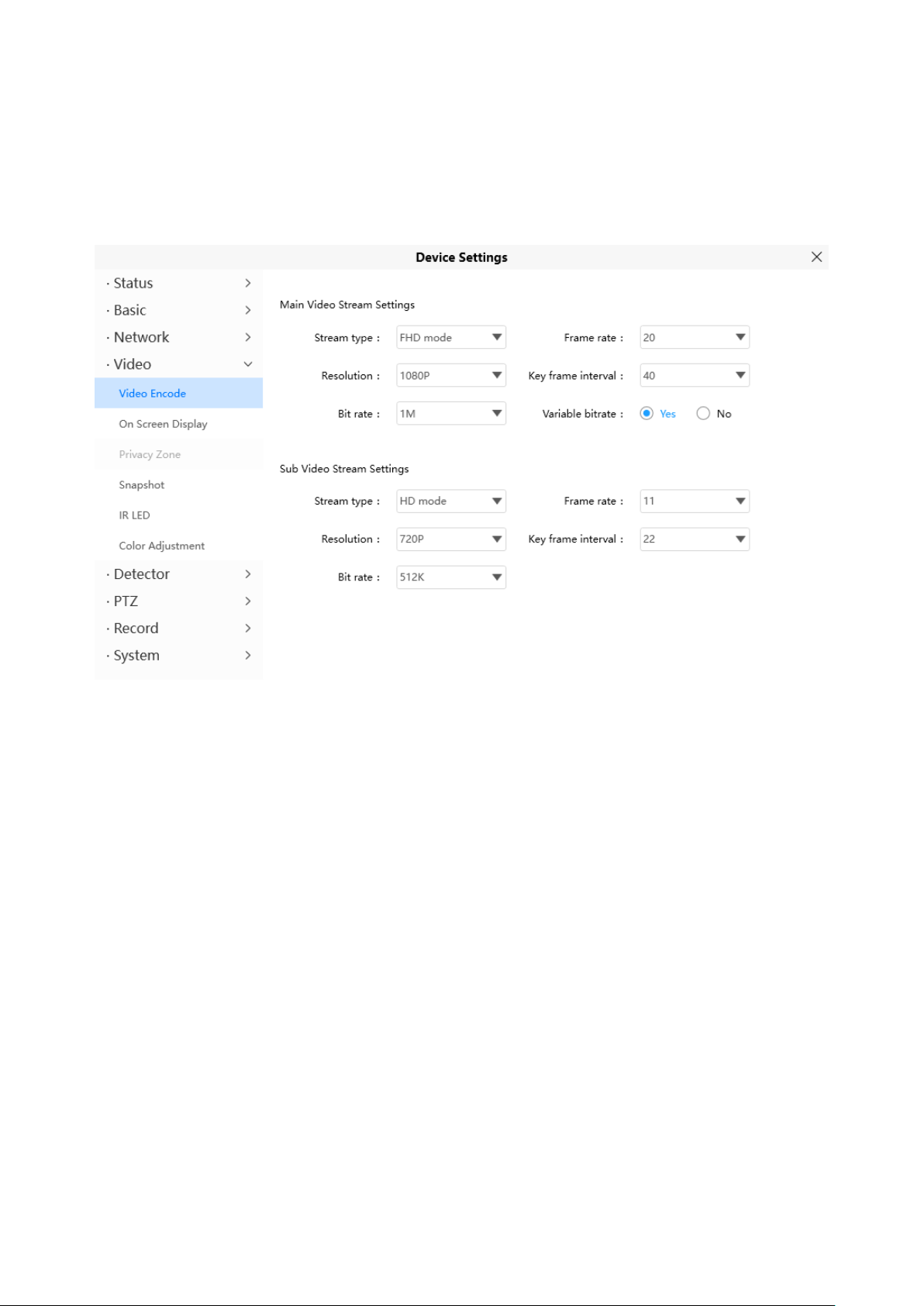
3.7.5 Video
This section allows you to configure Video stream settings, On screen display and Snapshot settings.
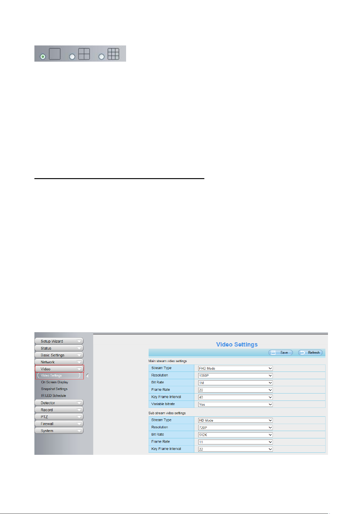
3.7.5.1 Video Settings
There are two ways to set the stream video settings. They are main stream video settings and sub
stream video settings.

40
Stream Type: There are four types to identify different streams you have set. If select the HD Mode, the
clearer video will become, and it will take up more bandwidth.
Resolution: The camera supports multiple types, For example: 2K, 1080P, 720P, VGA. The higher the
resolution is, the clearer video will become. But the code flux will become larger too, and it will take up
more bandwidth. (Different models support different specific types. )
Bit Rate: Generally speaking, the larger the bit rate is, the clearer video will become. But the bit rate
configuration should combine well with the network bandwidth. When the bandwidth is very narrow, and
bit rate is large, that will lead to video can not play well.
Frame Rate: Note that a larger frame size takes up more bandwidth. You should lower frame rate when
the bandwidth is limited. Normally, when the frame rate above 15, you can achieve fluently video.The
maximum frame rate for each model is different.
Key Frame Interval: The time between last key frame and next key frame. The shorter the duration, the
more likely you will get a better video quality, but at the cost of higher network bandwidth consumption.
Variable bitate:Tthe camera will change the video bit rate according to the situation, but will not more
than the maximum parameter "Bit Rate". You can select "Yes" or "No" " to turn on and off Variable Bitate
3.7.5.2 On Screen Display
This page is used to add timestamp and device name on the video.
Display Timestamp: There are two options: Yes or NO. Select Yes and you can see the system date on
the video.
Display Camera Name: There are two options: Yes or NO. Select Yes and you can see the device name

41
on the video.
3.7.5.3 Snapshot Settings
In this page you can set the snapshot pictures' image quality and the storage path.
Manual snap Quality: Low, Middle and High. The higher the quality, the picture will be clearer.
Pictures Save To: FTP or SD card. If you have done FTP and Alarm settings, when alarming, the
camera will snap pictures to the FTP or SD card automatically.
If you select the FTP, you can set the file name which the picture save to. For example: file name is
"NAME", the snapshot picture is "NAME_20150605-180000.jpg".
Enable timing to capture
To enable capture interval, follow the steps below:
1 Select Enable timing to capture
2 Capture interval: The interval time between two captures.
3 Select the capture time
Capture anytime
Click the black button up the MON, you will see all time range turn red. When something moving in
the detection area at anytime, the camera will capture.
Specify an capture schedule
Click the week day words, the corresponding column will be selected. For example, click TUE, the
all column of TUE turns to red, that means during Tuesday whole day, the camera will capture.
Press the left mouse and drag it on the time boxes, you can select the serial area,
4 Click Save button to take effect.

42
3.7.5.4 IR LED Schedule
1
2
4
5 6 3
7
On this page you can set the schedule time for switching IR LED lights. When parameter Mode is set to
the Schedule on the Live Video window, At these schedule time, the IR LED lights will be turned off.
3.7.6 Detection
This section allows you to configure Motion Detection and Motion Sound Detection.
3.7.6.1Motion Detection
IP Camera supports Motion Detection Alarm, when the motion has been detected, it will send emails or
upload images to FTP.
To enable motion detection, follow the steps below:
1 Enable Motion detection and Human Detect
2 Sensitivity--- The higher the sensitivity, the camera will be more easily alarmed. Select one motion
sensitivity.

43
3 Trigger interval--- The interval time between two motion detections. Here supports 5s / 6s / 7s / 8s /
9s / 10s / 11s / 12s / 13s / 14s / 15s. Select one interval time.
4 There are some alarm indicators:
A Camera Sound and PC Sound
If the camera has connected with a speaker or other audio output device, if you select Camera Sound or
PC Sound, when the motion has been detected, the people around the camera will hear beep alarm
sound.
B Send E-mail
If you want to receive alarm emails when motion is detected, you must select Send E-mail and set Mail
Settings first.
C Take Snapshot
If you select this checkbox, when the motion has been detected, the camera will snap the live view
window as a still picture and load it to the FTP. Make sure you have set FTP and set FTP as the storage
path in Video > Snapshot settings panel.
Time interval: The interval time between two pictures.
D Recording
If you select this checkbox, when the motion has been detected, the camera will recording and load it to
the FTP server. Make sure you have set FTP and set FTP as the storage path in Video > Snapshot
settings panel.
E Push message to the phone
If you select this checkbox, when the motion has been detected, the camera will push the message to
the phone which has been connected the camera.
5 Set Detection Area
Click set detect area and it pop up a window, then you can draw the detection area. Click Back button
after settings. When something moving in the detection area, the camera will alarm.

44
Click this button and select all time range .
6 Alarm Schedule
① Alarm anytime when motion is detected
Click the black button up the MON, you will see all time range turn red. When something moving in the
detection area at anytime, the camera will alarm.
② Specify an alarm schedule
Click the week day words, the corresponding column will be selected. For example, click TUE, the all
column of TUE turns to red, that means during Tuesday whole day, when something moving in the
detection area, the camera will alarm.

45
③ Press the left mouse and drag it on the time boxes, you can select the serial area,
7 Click Save button to take effect. When the motion is detected during the detection time in the detection
area, the camera will alarm and adopt the corresponding alarm indicators.
NOTE: You must set the detection area and detection schedule, or else there is no alarm anywhere and
anytime.
3.7.6.2Sound Detection
When the ambient sound over a certain decibel ,the sound alarm will be triggered.
If the Sensitivity is set to “High”, the camera will detect the sound whose more than 55db.
If the Sensitivity is set to “Medium”, the camera will detect the sound whose more than 65db.
If the Sensitivity is set to “Low”, the camera will detect the sound whose more than 75db.
46
If the Sensitivity is set to “Lower”, the camera will detect the sound whose more than 85db.
If the Sensitivity is set to “Lowest”, the camera will detect the sound whose more than 95db.
3.7.7 Record
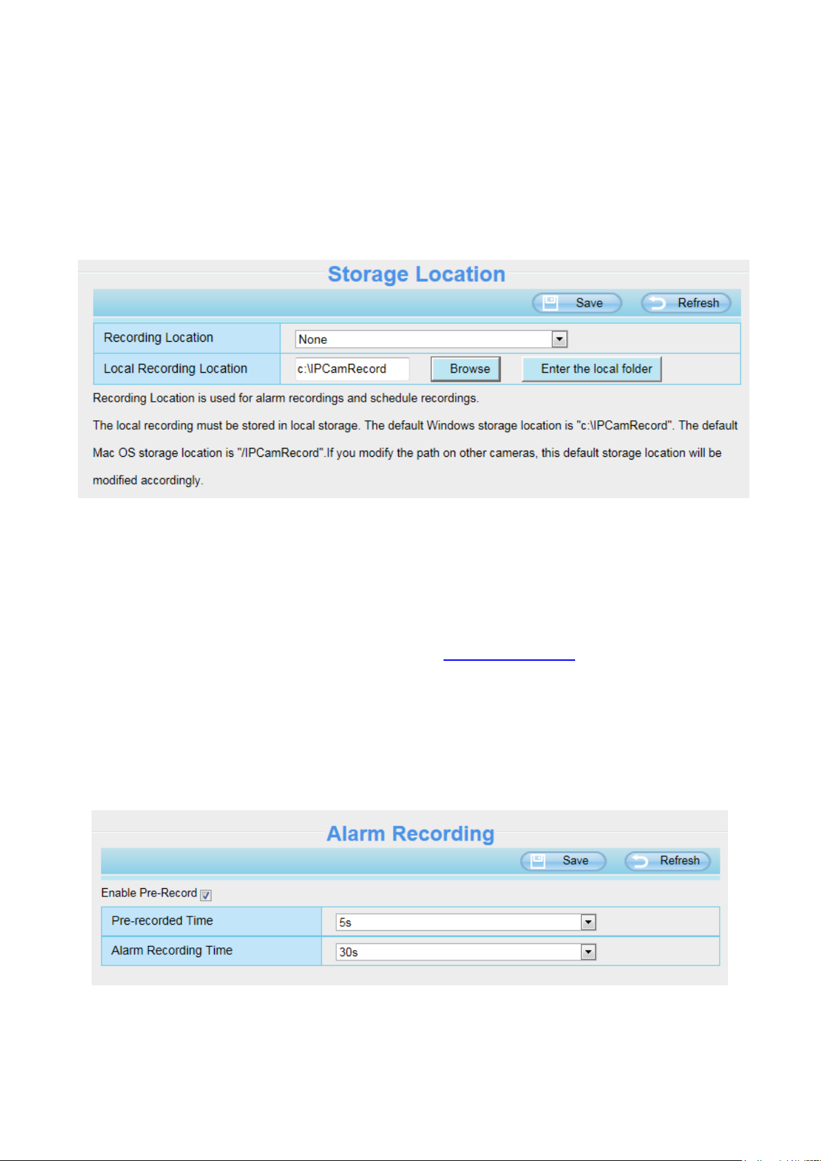
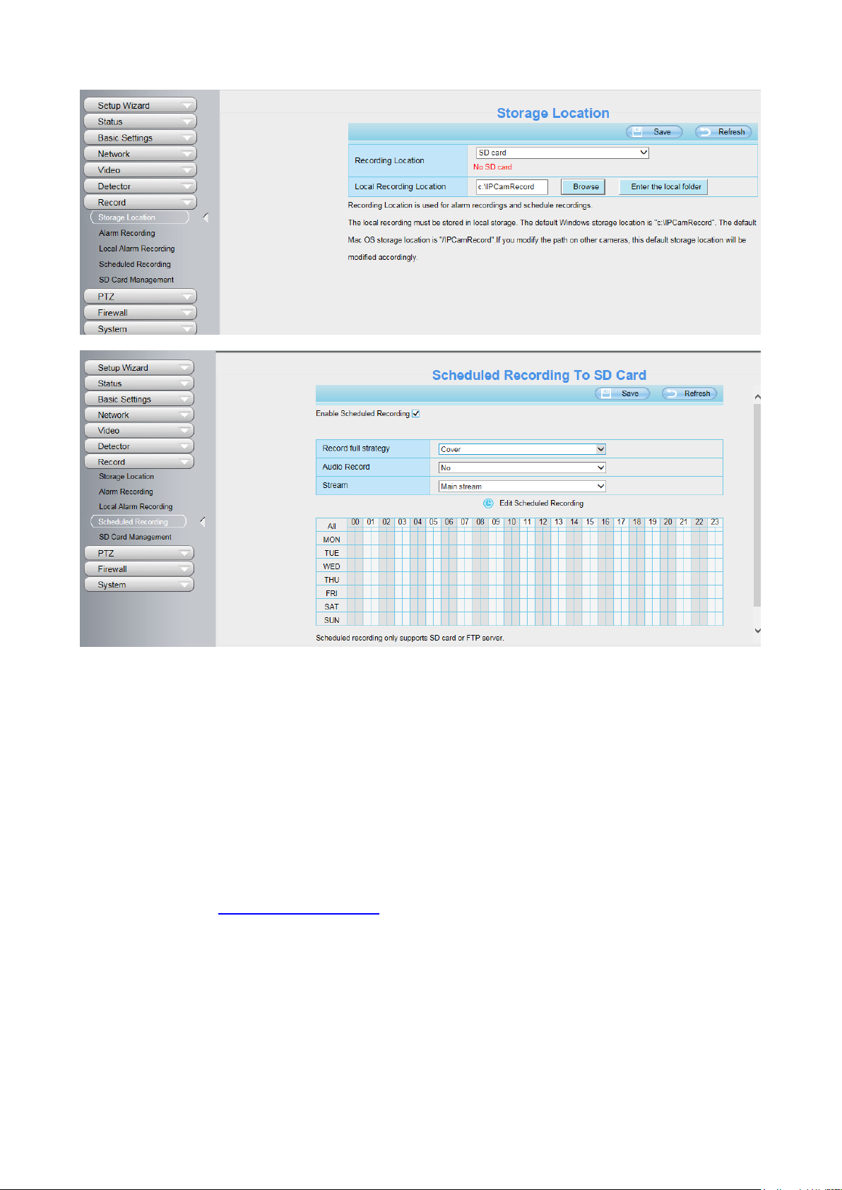
3.7.7.1 Storage Location
Recording Location: SD card, FTP.
SD card: The video will be saved in SD card. Make sure the camera has been inserted the SD
card. On this page, you can see the available space of the SD card.
FTP: The video will be saved in FTP. Please refer to 3.7.4.5 FTP Settings.
Local Recording Location: For Windows OS, the manual recording path is C:/ IPCamRecord, you can
change another one. For MAC OS, the manual recording path is: / IPCamRecord.
Enter the local folder: Click here,you can enter the local folder.
3.7.7.2 Alarm Recording
3.7.7.3 Local Alarm Recording
On this page you can enable local alarm record, and select the local alarm record time.
47
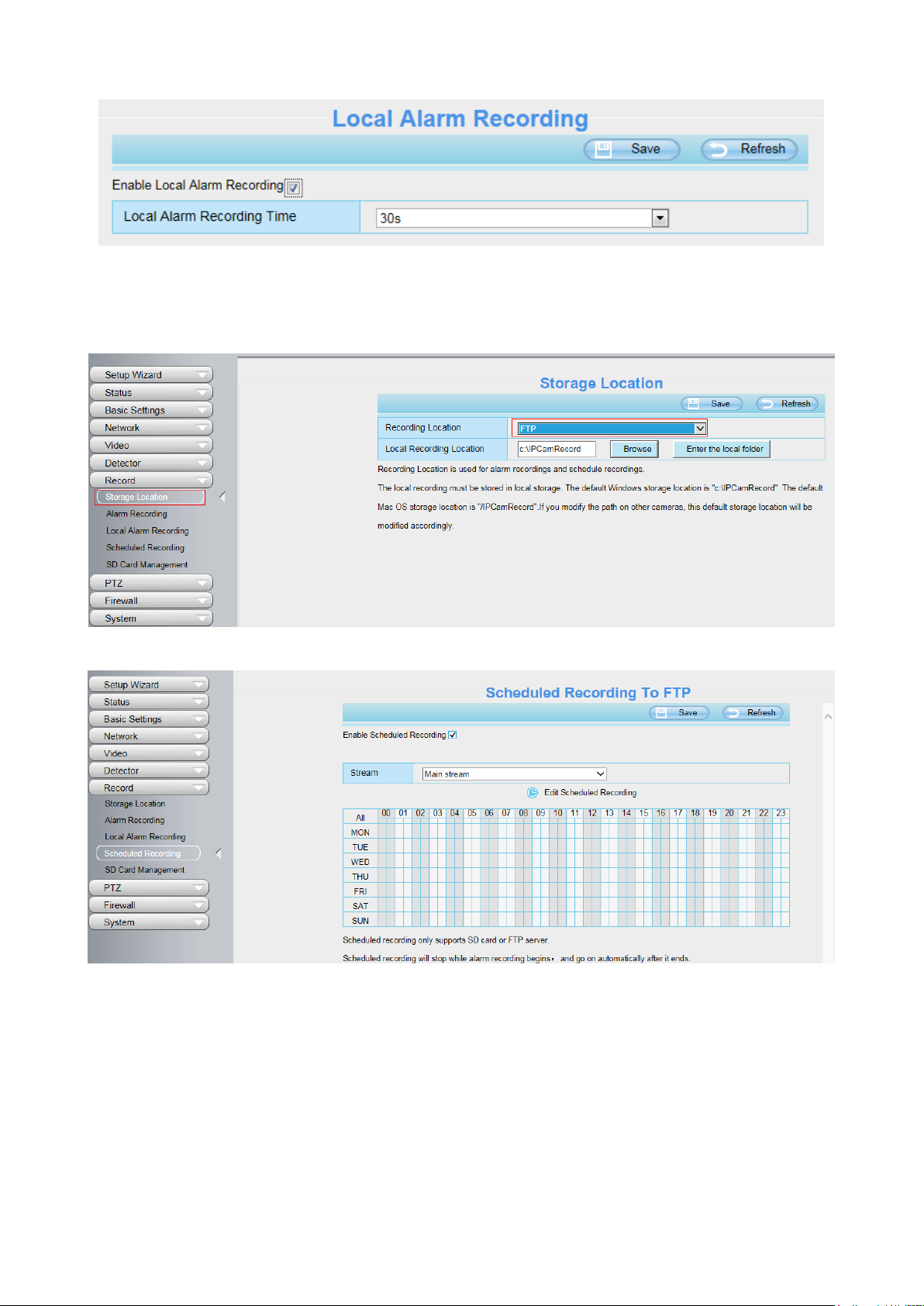
3.7.7.4 Schedule Recording
When the video is selected as FTP, the device supports scheduled recording.
When the video is selected as SD card, the device supports pumping frame recording.
48
Record frame: There are six frame selections, such as 1 / 30, 4 / 30, 8 / 30, 15 / 30, 24 / 30, 30 / 30.
Recommended default is 4 / 30. The greater the Frame rate is, the sharper picture quality is, and the
greater of storage space is, the shorter the storage time is.
Record full strategy: When the SD card is full, you can choose to cover the previous recording, or stop
recording.
NOTES:
Scheduled recording only supports video saved to the SD card or FTP server.
The schedule recording will stop while alarm recording is beginning, and it will continue
automatically after alarm recording end.
You can refer to 3.7.6.1 Motion Detection > 5 Alarm Schedule. in Alarm about editing the time of
recording Schedule.
3.7.7.5 SD Card Management
The SD card Slot inside the camera, if you want to install or remove the Micro SD card, you need to open
the camera.
When you plug in the Micro SD card during the camera work process, please reboot the camera again,
or else the SD Card may be cannot work well.
Go to the Settings > Status > Device Status page, you can see the SD card status.

49
The default storage path of alarm record files is SD card, when the available size of SD card is less than
256M, the old record files will be deleted automatically.
3.7.8 PTZ
This page will allow you to change the pan/tilt speed and do cruise tracks settings.
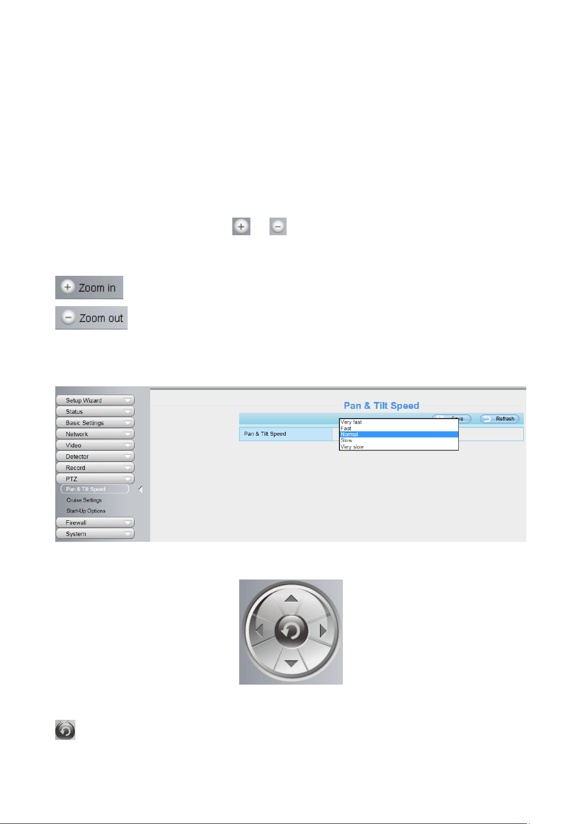
3.7.8.1 Pan & Tilt Speed
There are five Pt speed types: very fast, fast, normal, slow and very slowly. Select the desired PTZ
speed type and click save button.
There are three zoom speed types: fast, normal, slow.
3.7.8.2 Cruise Settings
This section explains how to add/ delete/ alter one cruise track.

50
Setting the Cruise Mode
Cruise mode:: Cruise time.
Cruise time: Select Cruise time from Cruise Mode drop-down, then you can set the Cruise time of the
camera.
Click Save to take effect.
Manage the Cruise Track
There are two default cruise tracks: Vertical and Horizontal.
Vertical: The camera will rotate from up to down
Horizontal: The camera will rotate form left to right.
Add: Add one cruise track, then click save button.
Delete: Select one cruise track and delete it.
Save: After you modify the Dwell time, you should click Save button to take effect.
Example
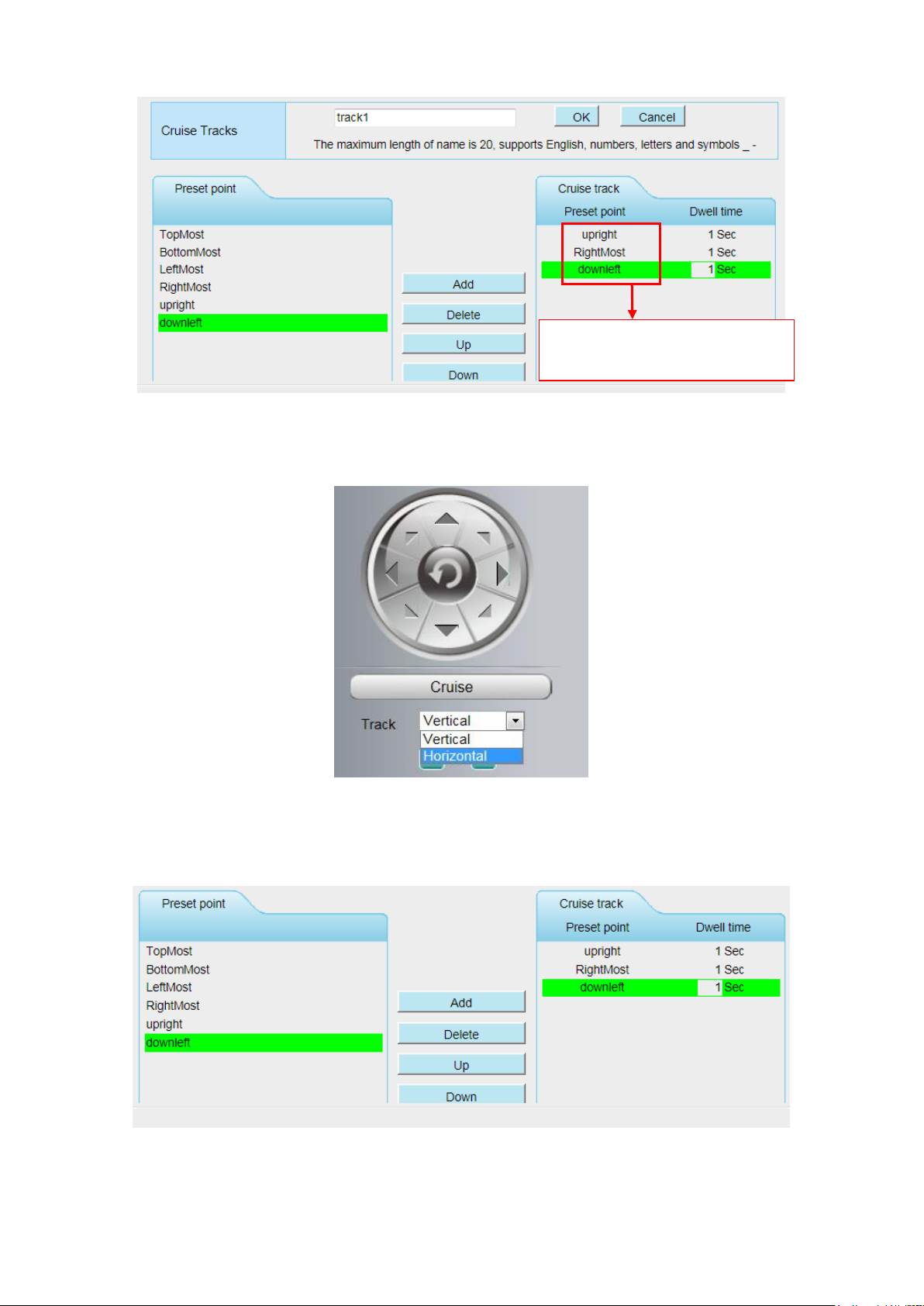
How to do add cruise tracks ?
Firstly, Click Add button and enter a descriptive name to identify the cruise track.
Secondly: On the lower left of the page, you can see all preset points you have added. Select one
preset point and click Add button, you can see the preset point has been added to the cruise track on the
cruise track page. You need to add two or more preset points to the cruise track.

51
The new added track name.
1 Select one preset point.
2 Click Add button.
Here you can see the preset point
has been added to one track. And
you can set the stay time.
Add the preset.
Thirdly: Click OK button and the cruise track will take effect.
You can add other cruise track as the same method.
For example: I have added three preset points to the “track 1”, that means : When I select the “track 1”
on the surveillance window, the camera moves as the following track: upright then Right Most last down
left.
You can add preset on the left of the surveillance window.
52
The cruise tracks have added
to the “track 1”.
After add the cruise track, back to the surveillance window, click Cruise, here you can see all cruise
tracks you have added.
There are other buttons between the Preset points and Cruise track, you can use these buttons to adjust
the order of preset points or add/delete one preset points in one cruise track.
Add: Select one preset points and add it to the selected cruise track.
Delete: Select one preset points you have added to one cruise track, click delete.
53
Move up/ down: Select one cruise track, adjust the order of preset points in one cruise track.
Attention:
Considering the life time and thermal issue of the motor, it‟s not recommend to do long-time cruise.
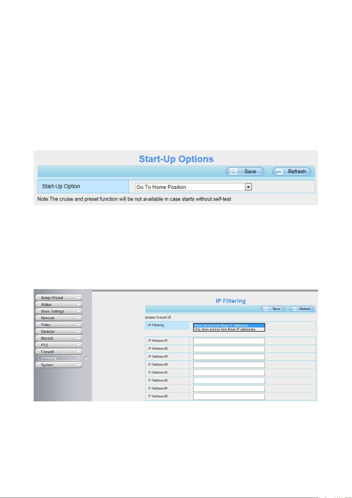
3.7.8.3 Start-Up Options
Here section will allow you to set the stop position after the camera reboots.
It supports three modes: No self test, Goto home position and Goto preset point.
No self test: When rebooting, the camera will not pan / tilt.
Goto home position: When rebooting, the camera will pa Providing Central Management Software to
manage or monitor multi-cameras n / tilt and stops at center.
Go to Preset point: Select one preset position and save it. When rebooting, the camera will pan/ tilt and
stops at the preset position you have set.
3.7.9 Firewall
This section explains how to control the access permission by checking the client PC's IP addresses. It is
composed of the following columns: Block access from these IP addresses and Only allow access
from these IP addresses.
Enable firewall, If you select Only allow access from these IP addresses and fill in 8 IP addresses at
most, only those clients whose IP addresses listed in the Only allow access from these IP addresses can
access the Network Camera. If you select Block access from these IP addresses, only those clients
whose IP addresses are in the IP list cannot access the Network Camera.
54
Click Save to take effect.
3.7.10 System
In this panel, you can backup/restore your camera settings, upgrade the firmware to the latest version,
restore the camera to default settings and reboot the device.
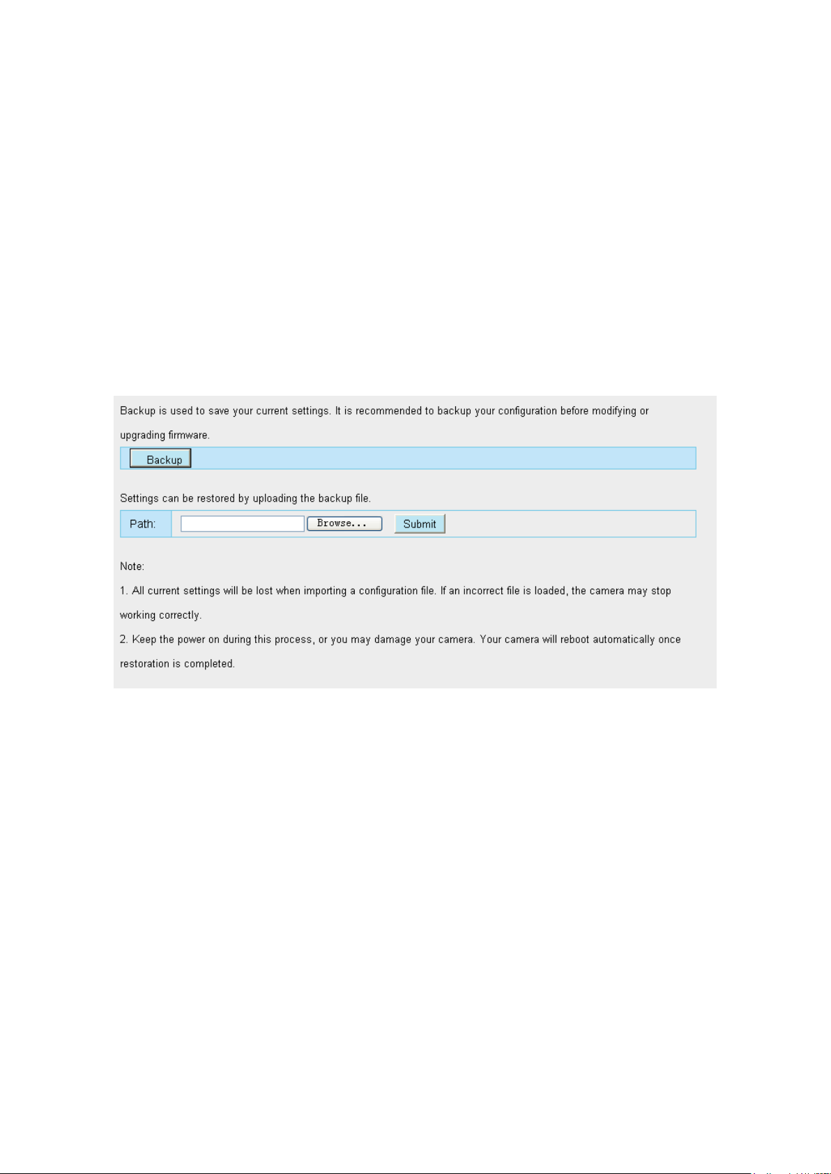
3.7.10.1 Back-up & Restore
Click Backup to save all the parameters you have set. These parameters will be stored in a bin file for
future use.
Click Browse and select the parameters file you have stored, then click Submit to restore the restore the
parameters.
3.7.10.2 System Upgrade
Click Download the latest firmware, you will see the following screen. And click Save to save the
firmware on your computer locally.
Your current firmware version will be displayed on your screen. You may go to the Status > Device
Information page to check for the latest firmware versions available.
Click Browse, choose the correct bin file and then click System upgrade.
Don't shut down the power during upgrading. After upgrading, you can see the upgrade result.

55
Upgrade Firmware by Equipment Search Tool
Double click the Equipment Search Tool shot icon , select the Camera IP that you want to
upgrade the firmware. Then select Upgrade Firmware and enter the username and password, choose
the firmware file, and upgrade.

56
CAUTION:
We recommend that you regularly update your camera to the latest available software and firmware
versions to help ensure the best experience for your camera.
NOTE:
1) Please ensure you have download the correct firmware package for your camera before upgrading.
Read the upgrade documentation (readme.txt file) in the upgrade package before you upgrade.
2) Upon downloading the firmware check the sizes of the .bin files. They must match the size in the
readme.txt file. If not, please download the firmware again until the sizes are the same. Your camera
will not function correctly if a corrupt .bin file is used.
3) Never shut down the power of the camera during upgrade until the IP camera restart and get
connected.
4) After upgrade successfully, please clear the cache of browser, uninstall the old plugin and re-install it,
then reset the camera to the default factory settings before using the camera.
3.7.10.3 Patch Installation
Click Browse to select the correct patch file, and then click Install Patch to install the patch. Do not turn
off the power during it installing. After installing is complete, you will receive a system prompt.

57
3.7.10.4 Factory Reset
Click Factory Reset button and all parameters will return to factory settings if selected.
The default administrator username is admin with a blank password.
3.7.10.5 Reboot
Click Reboot to reboot the camera. This is similar to unplugging the power to the camera.
3.8 Playback
On this page you can view the record files stored in the SD card.
Section 1 Define the Record files time and Type
: The storage path of record files
: Here supports three types: current day, current month and All records. Another
way, select the time on the time&date manually.

58
: The type of records files, Here supports two types: Normal record, Alarm
record and All records.
: Click this button to search all record files satisfy the conditions you selected.
Continuous Play: Select the checkbox to play continuously all the record files.
Section 2 Search record files
On this panel you can see all record files satisfy the conditions you set.
Section 3 Play / Stop / audio / Full screen Buttons
Please select one record file before use these buttons.
Click this button to play the record files.
Click this button to stop the record files.
Click this button to audio on / mute.
Click this button to make full screen, and double click left mouse to exit full screen.

59
4 Surveillance Software Foscam VMS
4.1 Hardware Connection & Software Installation
1. Connect the camera to the LAN network (Router or Switch) via network cable.
2. Visit Foscam official website foscam.com/vms , then you can find the “FoscamVMS_Beta”, Please
download it
4.2 Software Installation
1) Double click the software and follow the setup wizard to install the program.

60
2) The FoscamVMS icon will appear on the desktop automatically after a successful installation.
Note:
Sometimes the program will be treated as virus, so before installing, please add the software as trusted
program on your computer.
4.3 Create Acount
For your privacy and security, you can create a lacal adminstrator account.
you haven't created a local administator account, please click Create Account to create.
After creating a local administrator account, you can:
1. Use the account to log in to the client to ensure information security.
2. Create sub-accounts and assign different permissions for management.

61
4.4 Add Device
4.4.1 LAN Add
Click Add Device button, then follow below steps:
Step1 Select the device type , the default type is IPC(IP camera).
Step2 Click the IP address of the camera on the list.
Step3 Enter the username and password of the camera.
Step4 Click Add.

62
Please Note: Make sure the camera and PC are both in the same Local Area Network (LAN).
4.4.2 Manual LAN via IP
You can add the camera use manual LAN also. Click the Manual LAN first, then follow below steps:
Step1 Select the IP
Step2 Enter the IP and Port (IP and port can be viewed in Add Device)
Step3 Enter the username and password of the camera.
Step4 Click Add.

63
4.4.3 Manual LAN via P2P
You can add the camera use manual LAN also. Click the Manual LAN first, then follow below steps:
Step1 Select the P2P
Step2 Enter the UID (located on your camera)
Step3 Enter the username and password of the camera.
Step4 Click Add.
64
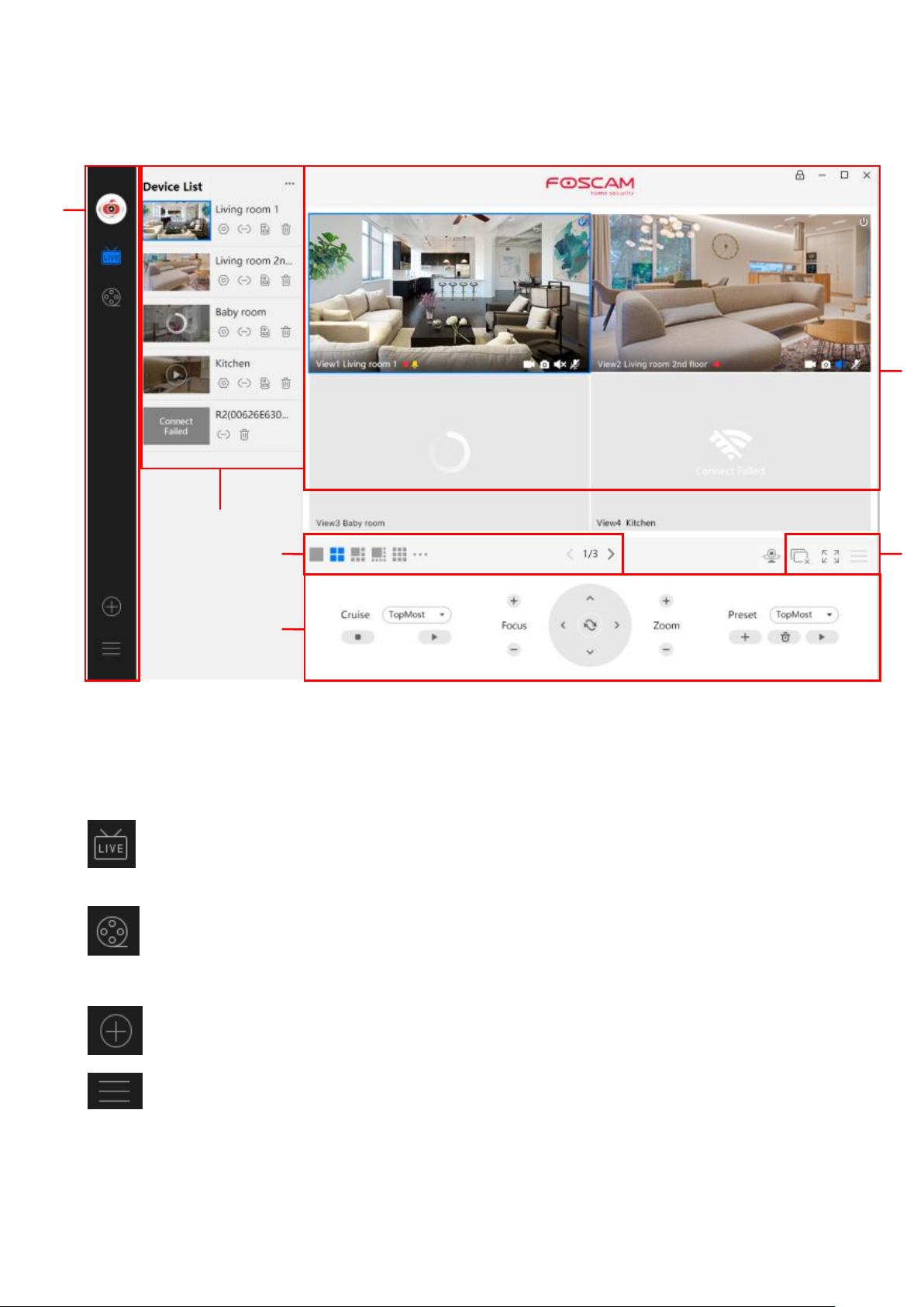
4.5 Surveillance Software GUI
1 2 3 4 5
6
First time you login the software, the whole video window is gray, you need to connect the cameras and
add cameras to it.
Section1 Menu Bar
Path to surveillance window. Click this button enter to Device List and back to the surveillance
window.
Playback the video recording, you can choose playback type and play video on local or
SD card.
Add Device, please refer chapter 3.4 for the detail setting.
More, You can Setting Personal Account, Preference, Left Bar and Switch Account.
Section2 Left Bar
65
Left Bar of Live: You can view the list of connected cameras
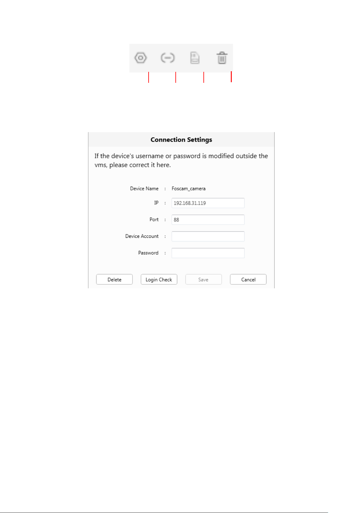
1
2 3 4
1----- Setup
Click the button Settings, goes to Device Settings Control Panel to make advanced camera settings.
2-----Device Connection Account
Click the button Settings, goes to connection Settings
3-----SD Card
This camera don„t support the SD card function. This function is not available
4-----Delete
Click the button, Delete the device.
66
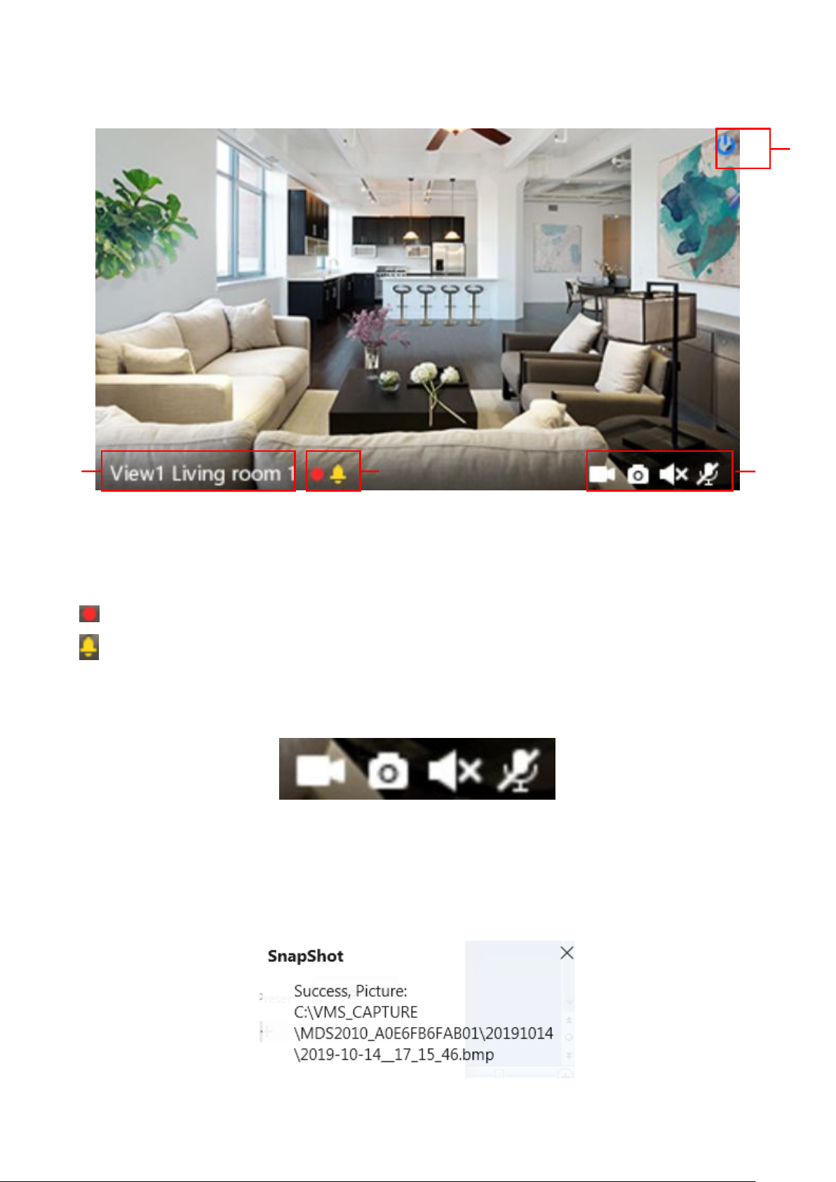
1
2
3
4
Record
Snap Shot
Sound
Talk
Section3 Live Window
1-----Close
Click the icon to close this channel live window
2-----Device Name
Show view channel and camera name.
3-----Recording and Alarm status
This icon will turn to red, it indicates that the camera is recording
This icon will turn to yellow, the motion is detected during the detection time in the detection area,
the camera alarm and adopt the corresponding alarm indicators
4----- Record / Snap Shot / Sound / Talk button
Record ----- Click it and do manually recording. When recording, icon 1 will turn to blue. Click it again
and stop recording. The recording files will be stored to C disk automatically
Snap Shot ----- Click it to make snapshot. After snapshot, the button banner will prompt Captured
Successfully. And you can find the picture on default path C:\VMS_CAPTURE
67
Sound ----- Click the icon then you will hear sound captured by the camera's built-in microphone. You
may need to plug in earphones or enable the computer speakers to hear from the camera's microphone.
Make sure the camera supports audio. Click again and stop audio.
Talk ----- Click the button, then talk to the microphone that connected with PC, people around the
camera can here you voice. Click the icon again and stop talking.
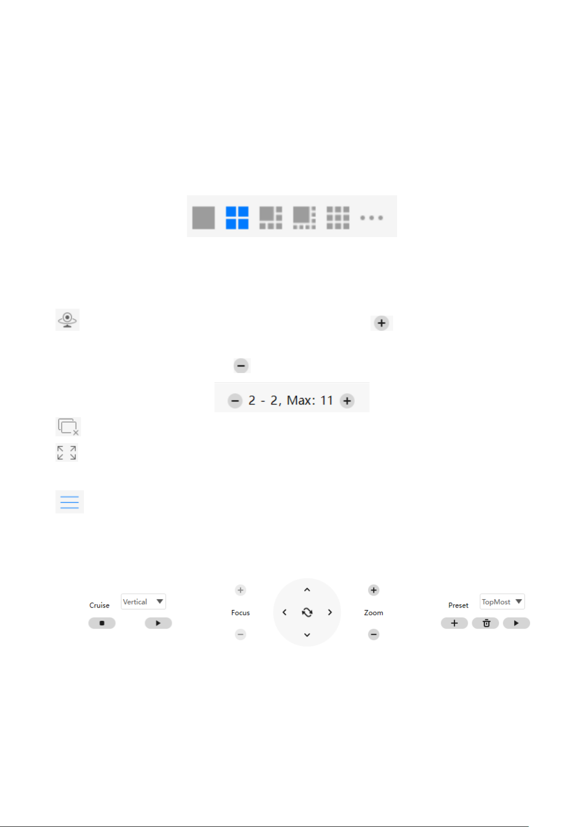
Section4 The number of split-screen
Click this button to select the number of split-screen on one page.
The client can monitor many cameras at one page, here you can choose the display number. The
maximum number is 16.
Section5 Live Cruise / Close All / Full Screen / Hide Bar
Live Cruise ----- Click this button to Live Cruise, you can click button to add a loop page for
live
Cruise or click button to reduce the loop page for live Cruise.
Close All ----- Click this button to close all the cameras
Full Screen ----- Click this button to enter full screen, Click this button to enter full screen, then
click to exit full screen.
Hide Bar ----- Click this button, Hide and show Pan / Tilt control Bar
Section6 Cruise / Focus buttons / Pan / Tilt control / Zoom buttons/ Preset
68
Select one of these.
Cruise Settings
The default cruise tracks have two types: Vertical and Horizontal.
Vertical: The camera will rotate from up to down.
Horizontal: The camera will rotate from left to right.
:Start cruise. : Stop cruise.
If you want to define or change the cruise trace, please go to Device Settings → PTZ → Cruise
Settings panel.
How to do cruise?
Firstly: Select one track in the track dropdown list.
Secondly: Click Start cruise button, the camera will cruise following the predefined path.
Thirdly: Click stop button and finish cruising.
Zoom in” or ”Zoom out”
Click or ,The focal length of the camera lens will be larger or shrink, you can adjust the focus
distance to the target object size, access to high-definition screen.
Focus: Optical zoom
Zoom: Magic Zoom
69
Pan/Tilt Control
1 2 3
4
1----- Up control button, 2-----Down control button,
3------Left control button, 4------Right control button,
Click this button and go to center
Preset settings
IP Camera supports 16 preset positions, which is considered enough for DIY home & small business
surveillance market
The default preset position is Topmost, Bottom most, Left most, right most, you can add other preset
positions.
Add Click this icon to save the position you need the camera to remember
Delete Select one preset position and click this button to delete it.
GO Select one preset position in the preset drop-down list and click Go to make the camera
move the preset position
How to do preset position?
Firstly, move the camera and stop at a desired place where you want make preset position.
Secondly, click button and enter a descriptive name for the preset position. The preset position
cannot contain special characters. Then click OK to save it. If you want to reset the preset position, click
Cancel.
After that, you can move the camera and stop at another place, and set another preset position. You can
do all the 16 preset positions with this method.
If you want to see one preset position you have set, only select the preset position name from the preset
drop-down list, and click go button, the camera will go to the preset position.
70
4.6 Advanced Camera Settings
Click the button, goes to Device Settings to make advanced camera settings.
4.6.1 Status
Status contains two columns: Device Information and Logs, it will show you
various information about your camera.
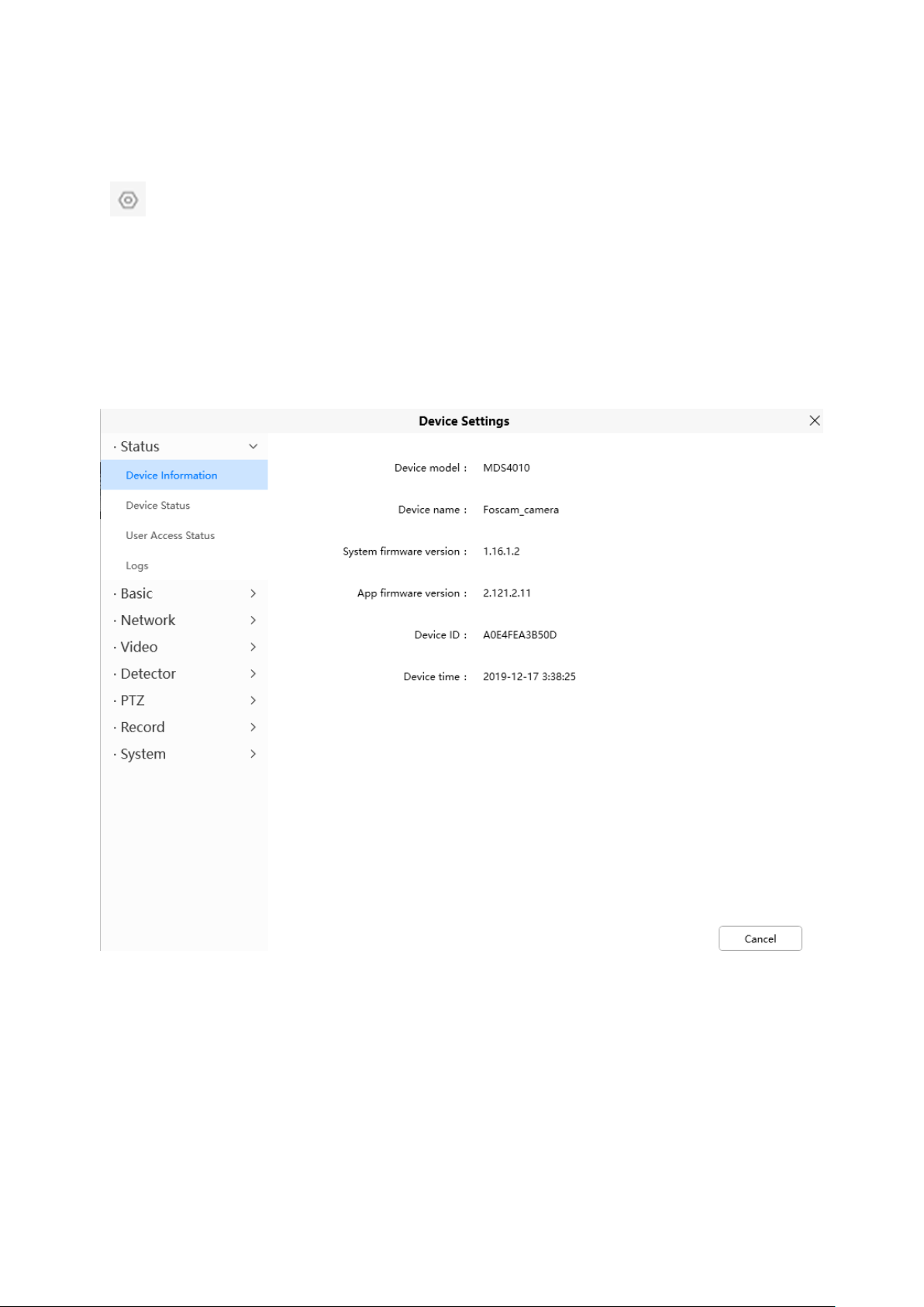
4.6.1.1 Device Information
Device Model: The model of the device.
Device Name: The Device Name is a unique name that you can give to your device to help you identify it.
Click Basic Settings and go to Camera Name panel where you can change your camera name. The default
device name is Foscam_camera.
System Firmware Version: Display the System Firmware version of your camera.
App Firmware Version: Display the application firmware version of your camera.

71
Device ID: Display the MAC address of your camera. For example Device ID is 00626EE96E3C, the same
MAC ID sticker is found at the bottom of the camera.
Device Time: The system time of the device. Click Basic Settings and go to Device Time panel and adjust
the time.
4.6.1.2 Device Status
On this page you can see device status such as Alarm status, NTP status, IR LED Status and so on.
4.6.1.3 User Access Status
Session status will display who and which IP is visiting the camera now

72
4.6.1.4 Logs
Click the page number and go to the
corresponding page to see more logs
Full in one page number, click go GO button and
go to the corresponding page.
The log record shows who and which IP address accessed or log out the camera.
4.6.2 Basic
This section allows you to configure your Device Name, Time, User Accounts, Status Light and Voice Prompt.
4.6.2.1 Camera Name
Default alias is Foscam_camera. You can define a name for your camera here such as apple. Click Save to
save your changes. The alias name cannot contain special characters.
4.6.2.2 Device Time
This section allows you to configure the settings of the internal system clocks for your camera.

73
Time Zone: Select the time zone for your region from the dropdown menu.
Sync with NTP server: Network Time Protocol will synchronize your camera with an Internet time server.
Choose the one that is closest to your camera.
Use DST: Select the use DST (Daylight Saving Time, to set the clock ahead of the real-time), then set the start
time and end time of the DST, select the daylight saving time from the drop-down menu at last.
Click Save button and submit your settings.
4.6.2.3 User Accounts
Here you can create users and set privilege, visitor, operator or administrator. The default administrator user
accounts are administrator with a blank password.
How to change the password?

74
Firstly, select the account which you want to change the password, then select Change password, enter the
old password and the new password, lastly click modify to take effect.
How to change the username?
Select the account which you want to change the username, then select Change username, enter the new
username and the password, lastly click modify to take effect.
.
4.6.2.4 Status Light
If you have a power and network status light on your camera, you can turn it on and off with this feature. This
camera don„t have the status light described above.

75
4.6.2.5 Voice Prompt
You can set the voice prompt on the camera to turn on and off if you connect an external audio
device.
4.6.3 Network
This section will allow you to configure your camera's information.
4.6.3.1 IP
If you want to set a static IP for the camera, please go to IP page. Keep the camera in the same subnet of your
router or computer.

76
It is recommended that you use the subnet mask, gateway and DNS server from your locally attached PC. If
you don't know the subnet mask, gateway and DNS server, you can check your computer's local area
connection as follows:
Control Panel--Network Connections--Local Area Connections --Choose Support--Details.

77
Click the button
to search for wireless
networks.
If you don't know the DNS server, you can use the same settings as the Default Gateway.
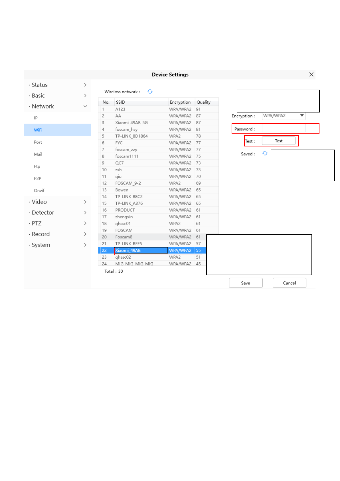
4.6.3.2 WiFi
Step 1: Click the button and the camera will detect all wireless networks around the area. It should also
display your router in the list.
78
Step 2: Click the SSID (name of your router) in the list, the corresponding information related to your network,
1 Click the SSID of your router
and the relevant information
will be filled in the fields
automatically.
2 Enter the password of
your router .
3 Click Test to check
if the password is
correct or not.
such as the name and the encryption, will be filled into the relevant fields automatically.
You will only need to fill in the password of your network. Make sure that the SSID, Encryption and the
password you filled in are exactly the same for your router.
Step 3: Please click on the Save button after all settings have been entered and disconnect the network cable.
Never shut down the power of the camera until the IP camera is able to connect to the wireless network.
The LAN IP address will disappear on the window of Add Device when the camera is configuring a
wireless connection. Wait about 1 minute, the camera should obtain a wireless connection, and the LAN IP of
the camera will show again on the window of Add Device The IP address may have changed
after the camera receives a wireless connection; we recommend setting a static local IP address if this IP
address changes by right clicking the camera in Equipment Search Tool, setting a static IP, and pushing OK .
Congratulations! You have set up the wireless connection of the camera successfully.
NOTE: If you fail to make a wireless connection, please refer to your seller or contact us directly for
assistance.
4.6.3.3 Port
This camera supports HTTP Port / HTTPS Port/ ONVIF Port. HTTP Port is used to access the camera
remotely.
HTTP port: By default, the HTTP is set to 88. Also, they can be assigned with another port number between 1
and 65535. But make sure they can not be conflict with other existing ports like 25, 21.
79
1
2 3 6
5
5
4.6.3.4 Mail Settings
If you want the camera to send emails when motion has been detected, here Mail will need to be configured.
1----- SMTP Server/ Port /Transport Layer Security Enter SMTP server for sender. SMTP port is usually
set as 25. Some SMTP servers have their own port, such as 587 or 465, and Transport Layer Security usually
is None. If you use Gmail, Transport Layer Security must be set to TLS or STARTTLS and SMTP Port must be
set to 465 or 25 or 587, which port you choose should be decided by which Transport Layer Security you
select.
2----- SMTP Account/ password ID account and password of the sender email address

80
3----- E-mail Sender Mailbox for sender must support SMTP
4----- Receiver Mailbox for receiver need not support SMTP, you can set 4 receivers
5----- Save Click Save to take effect
6----- Test Click Test to see if Mail has been successfully configured.
Click Test to see if Mail has been successfully configured.
If the test success, you can see the Success behind the Test, at the same time the receivers will receive a test
mail.
If the test fails with one of the following errors after clicking Test, verify that the information you entered is
correct and again select Test .
1) Cannot connect to the server
2) Network Error. Please try later
3) Server Error
4) Incorrect user or password
5) The sender is denied by the server. Maybe the server need to authenticate the user, please check it and try
again
6) The receiver is denied by the server. Maybe because of the anti-spam privacy of the server
7) The message is denied by the server. Maybe because of the anti-spam privacy of the server
8) The server does not support the authentication mode used by the device.
4.6.3.5 FTP
If you want to upload record images to your FTP server, you can set FTP.
81
FTP server: If your FTP server is located on the LAN, you can set as Figure a.
If you have an FTP server which you can access on the internet, you can set as Figure b.
Port: Default is port 21. If changed, external FTP client program must change the server connection port
accordingly.
Mode: Here supports two modes: PORT and PASV.
Username / password: The FTP account and password.
Click Save to take effect.
Click Test to see if FTP has been successfully configured.
4.6.3.6 P2P
Access the camera by smart phone (Android or iOS operating system)
First of all, you need to open the P2P function of the camera at > Network > P2P.
4.6.3.7 Onvif
By default, the ONVIF port is set to 888. Also, they can be assigned with another port number
between 1 and 65535 (except 0 and 65534). But make sure they can not be conflict with other existing ports.
82
4.6.4 Video
This section allows you to configure Video Encode settings, On screen display, Snapshot and IR LED settings.
4.6.4.1 Video Encode
This is main Encode video settings.
Stream type: There are four types to identify different streams you have set.
Resolution: The camera supports multiple types, For example: 1080P, 720P, VGA. The higher the
resolution is, the clearer video will become. But the code flux will become larger too, and it will take up more
bandwidth. (Different models support different specific types. )
Bit Rate: Generally speaking, the larger the bit rate is, the clearer video will become. But the bit rate
configuration should combine well with the network bandwidth. When the bandwidth is very narrow, and bit rate
is large, that will lead to video can not play well.
Frame Rate: Note that a larger frame size takes up more bandwidth. When the video format is 50Hz, the
maximum frame rate is 25 fps. When the video format is 60Hz, the maximum frame rate is 30 fps. You should
lower frame rate when the bandwidth is limited. Normally, when the frame rate above 15, you can achieve
fluently video.
Key Frame Interval: The time between last key frame and next key frame. The shorter the duration, the more
likely you will get a better video quality, but at the cost of higher network bandwidth consumption.
Variable Bitrate: Select the Bit rate type to constant or variable. If select Yes, the camera will change the
video bit rate according to the situation, but will not more than the maximum parameter "Bit Rate"; If select No,
the Bit Rate is unchanged.

83
4.6.4.2 On Screen Display
This page is used to add timestamp and device name on the video.
Display Timestamp: There are two options: Yes or NO. Select Yes and you can see the system date on the
video,
Display Camera Name: There are two options: Yes or NO. Select Yes and you can see the device name on
the video.
4.6.4.3 Snapshot
On this page you can set the snapshot pictures' image quality and the storage path.
Manual Snap Quality: Low, Middle and High. The higher the quality, the picture will be clearer.
Pictures Save To: FTP. If you have done FTP and Alarm settings, when alarming, the camera will snap
pictures to the FTP automatically. If you select the FTP, you can set the file name which the picture save to.
Enable Timing to Capture
To enable capture interval, follow the steps below:
1 Select Enable timing to capture
2 Capture interval: The interval time between two captures.

84
3 Select the capture time
Capture anytime
Click the black button up the MON, you will see all time range turn red. When something moving in the
detection area at anytime, the camera will capture.
Specify an capture schedule
Click the week day words, the corresponding column will be selected. For example, click TUE, the all
column of TUE turns to red, that means during Tuesday whole day, the camera will capture.
Press the left mouse and drag it on the time boxes, you can select the serial area,
4 Click Save button to take effect.
4.6.4.4 IR LED
There are three modes to set the IR LED lights.
Auto: The default mode is auto. On this mode, IR LED lights will be switched automatically depended on the
brightness of enviroment.
Manual: On this mode, you can click On option to turn on the IR LED lights, and click Off option to turn off the
IR LED lights.
Schedule: On this mode, IR LED lights will be turned off during the setting schedule .You can set the period of
time during which the infrared lamp is turned off to prevent your baby from being influenced during sleep. You
can also turn off the infrared lamp on the video preview page at any time.

85
4.6.4.5 Color Adjustment
You can adjust the settings to your liking.
4.6.5 Detector
4.6.5.1 Motion Detection
IP Camera supports Motion Detection Alarm, when the motion has been detected, it will send emails or
upload images to FTP.

86
1
2
3 4 5 6 7
To enable motion detection, follow the steps below:
1 Enable Detection Switch
2 Sensitivity---- It supports three modes: Low, Middle and High. The higher the sensitivity, the camera will be
more easily alarmed. Select one motion sensitivity.
3 Trigger Interval----The interval time between two motion detections. Here supports
5s/6s/7s/8s/9s/10s/11s/12s/13s/14s/15s. Select one interval time.
4 Snap Interval---- The interval time between two pictures.
5 Select the alarm indicators
There are some alarm indicators:
A Camera Sound
If you select Camera Sound, when the motion has been detected, the people around the Camera will hear
beep alarm sound, if the device is connected with the audio output device.
B PC Sound
If you select PC Sound, when the motion has been detected, the people around the PC will hear beep alarm
sound.
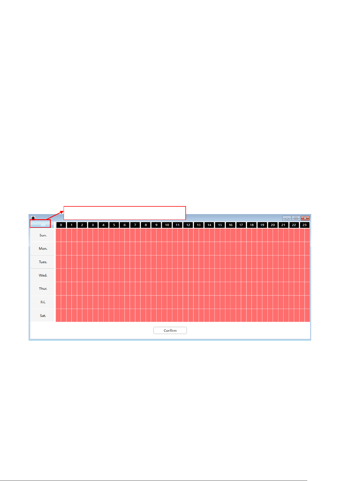
87
C Send E-mail
Click this button and select all time range.
If you want to receive alarm emails when motion is detected, you must select Send E-mail and set Mail
Settings first.
D Recording
If you select this checkbox, when the motion has been detected, the camera will recording and load it to the
FTP server. Make sure you have set FTP and set FTP as the storage path in Video->Snapshot settings panel
.
E Take Snapshot
If you select this checkbox, when the motion has been detected, the camera will snap the live view window as
a still picture and load it to the FTP. Make sure you have set the storage path in Video > Snapshot Settings
panel.
F Push message to the phone
If you select this checkbox, when the motion has been detected, the camera will push the message to the
phone which has been connected the camera.
6 Alarm Schedule
1. Alarm anytime when motion is detected
Click the black button up the MON, you will see all time range turn red. When something moving in the
detection area at anytime, the camera will alarm.
2. Specify an alarm schedule
Click the week day words, the corresponding column will be selected. For example, click TUE, the all column
of TUE turns to red, that means during Tuesday whole day, when something moving in the detection area, the
camera will alarm.

88
3. Press the left mouse and drag it on the time boxes, you can select the serial area,
7 Click Save button to take effect. When the motion is detected during the detection time in the detection area,
the camera will alarm and adopt the corresponding alarm indicators.
NOTE: You must set the detection area and detection schedule, or else there is no alarm anywhere and
anytime.
4.6.5.2 Sound Detection
When the ambient sound over a certain decibel ,the sound alarm will be triggered.

89
1
2
3 4 5 6 7
To enable motion detection, follow the steps below:
1 Enable Detection Switch
2 Sensitivity---- It supports three modes: Low, Middle and High. The higher the sensitivity, the camera will be
more easily alarmed. Select one motion sensitivity.
3 Trigger Interval----The interval time between two motion detections. Here supports
5s/6s/7s/8s/9s/10s/11s/12s/13s/14s/15s. Select one interval time.
4 Snap Interval---- The interval time between two pictures.
5 Select the alarm indicators
There are some alarm indicators:
A Camera Sound
If you select Camera Sound, when the sound has been detected, the people around the Camera will hear beep
alarm sound, if the device is connected with the audio output device.
B PC Sound
If you select PC Sound, when the sound has been detected, the people around the PC will hear beep alarm
sound.

90
C Send E-mail
Click this button and select all time range.
If you want to receive alarm emails when motion is detected, you must select Send E-mail and set Mail
Settings first.
D Recording
If you select this checkbox, when the sound has been detected, the camera will recording and load it to the
FTP server. Make sure you have set FTP and set FTP as the storage path in Video->Snapshot settings panel
.
E Take Snapshot
If you select this checkbox, when the sound has been detected, the camera will snap the live view window as a
still picture and load it to the FTP. Make sure you have set the storage path in Video > Snapshot Settings
panel.
F Push message to the phone
If you select this checkbox, when the sound has been detected, the camera will push the message to the
phone which has been connected the camera.
6 Alarm Schedule
4. Alarm anytime when sound is detected
Click the black button up the MON, you will see all time range turn red. When something moving in the
detection area at anytime, the camera will alarm.
5. Specify an alarm schedule
Click the week day words, the corresponding column will be selected. For example, click TUE, the all column
of TUE turns to red, that means during Tuesday whole day, when something sound in the detection area, the
camera will alarm.

91
6. Press the left mouse and drag it on the time boxes, you can select the serial area,
7 Click Save button to take effect. When the sound is detected during the detection time in the detection area,
the camera will alarm and adopt the corresponding alarm indicators.
NOTE: You must set the detection area and detection schedule, or else there is no alarm anywhere and
anytime.
4.6.6 PTZ
This page will allow you to change the pan/tilt speed and do cruise tracks settings.
4.6.6.1 PTZ Parameters
There are five Pt speed types: very fast, fast, normal, slow and very slowly. Select the desired PTZ
speed type and click save button.

92
There are three zoom speed types: fast, normal, slow
4.6.6.2 Cruise Settings
This section explains how to add/ delete/ alter one cruise track.
Setting the Cruise Mode
Cruise mode: Cruise time.
Cruise time: Select Cruise time from Cruise Mode drop-down, then you can set the Cruise time of the
camera.
Click Save to take effect.

93
Manage the Cruise Track
There are two default cruise tracks: Vertical and Horizontal.
Vertical: The camera will rotate from up to down
Horizontal: The camera will rotate form left to right.
Add: Add one cruise track, then click save button.
Delete: Select one cruise track and delete it.
Save: After you modify the Dwell time, you should click Save button to take effect.
Example
How to do add cruise tracks ?
Firstly, Click Add button and enter a descriptive name to identify the cruise track.
Secondly: On the lower left of the page, you can see all preset points you have added. Select one preset point
and click Add button, you can see the preset point has been added to the cruise track on the cruise track page.
You need to add two or more preset points to the cruise track.
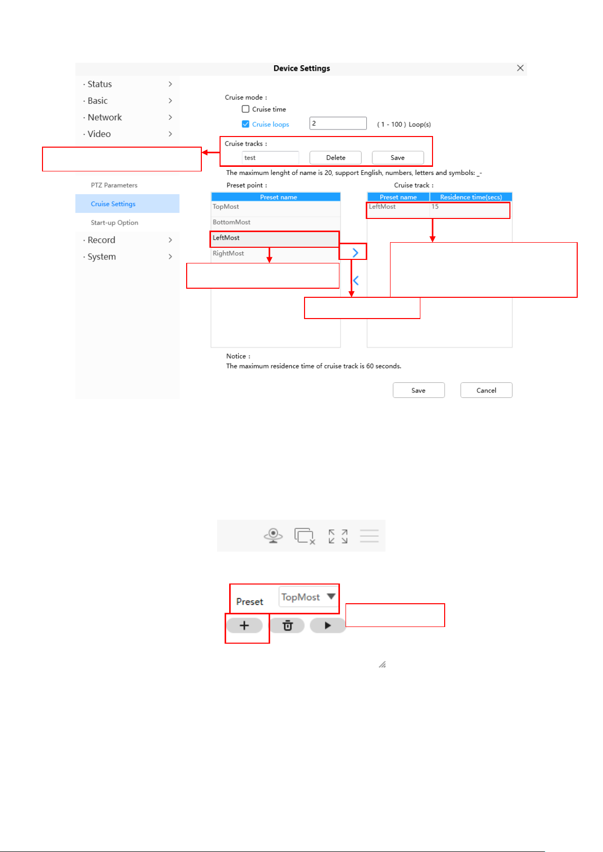
94
The new added track name.
1 Select one preset point.
2 Click Add button.
Here you can see the preset point
has been added to one track. And
you can set the stay time.
Add the preset.
Thirdly: Click Save button and the cruise track will take effect.
You can add other cruise track as the same method.
For example: I have added three preset points to the “track 1”, that means : When I select the “track 1” on the
surveillance window, the camera moves as the following track: upright then Right Most last down left.
You can add preset on the left of the surveillance window.

95
The cruise tracks have added
to the “track 1”.
After add the cruise track, back to the surveillance window, click Cruise, here you can see all cruise tracks you
have added.
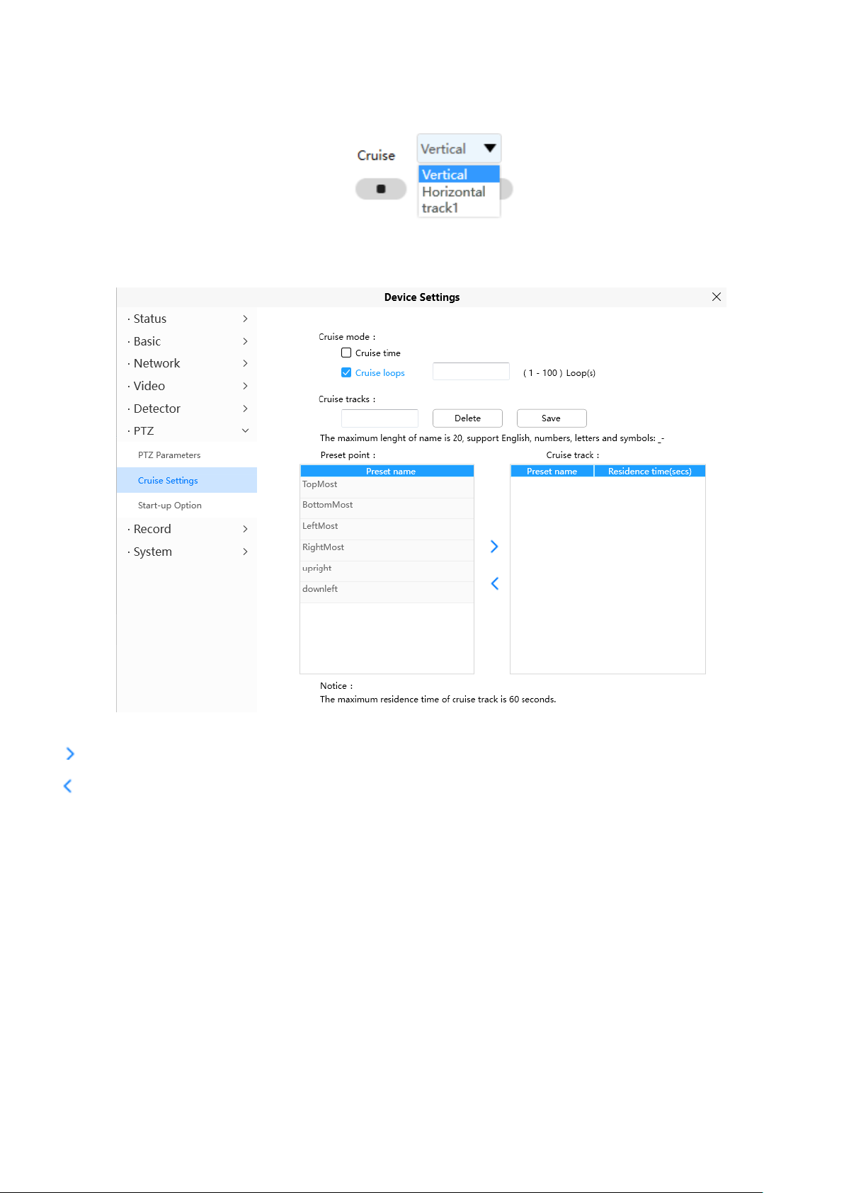
96
There are other buttons between the Preset points and Cruise track, you can use these buttons to adjust the
order of preset points or add/delete one preset points in one cruise track.
: Select one preset points and add it to the selected cruise track.
: Select one preset points you have added to one cruise track, click delete.
Attention:
Considering the life time and thermal issue of the motor, it‟s not recommend to do long-time cruise.
4.6.6.3 Start-Up Options
Here section will allow you to set the stop position after the camera reboots.
It supports three modes: No self test, Goto home position and Goto preset point.
Disable Start-up: When rebooting, the camera will not pan / tilt.
Goto home position: When rebooting, the camera will pa Providing Central Management Software to
manage or monitor multi-cameras n / tilt and stops at center.
Go to Preset pointion: Select one preset position and save it. When rebooting, the camera will pan/ tilt and
stops at the preset position you have set.

97
4.6.7 Record
4.6.7.1 Storage Management
On this page you can choose Record Storage Path. The record storage path default is No Path
4.6.7.2 Alarm Recording
On this page you can configure the Alarm-recording Time, Enable pre-recorded time and Pre-Record Time.
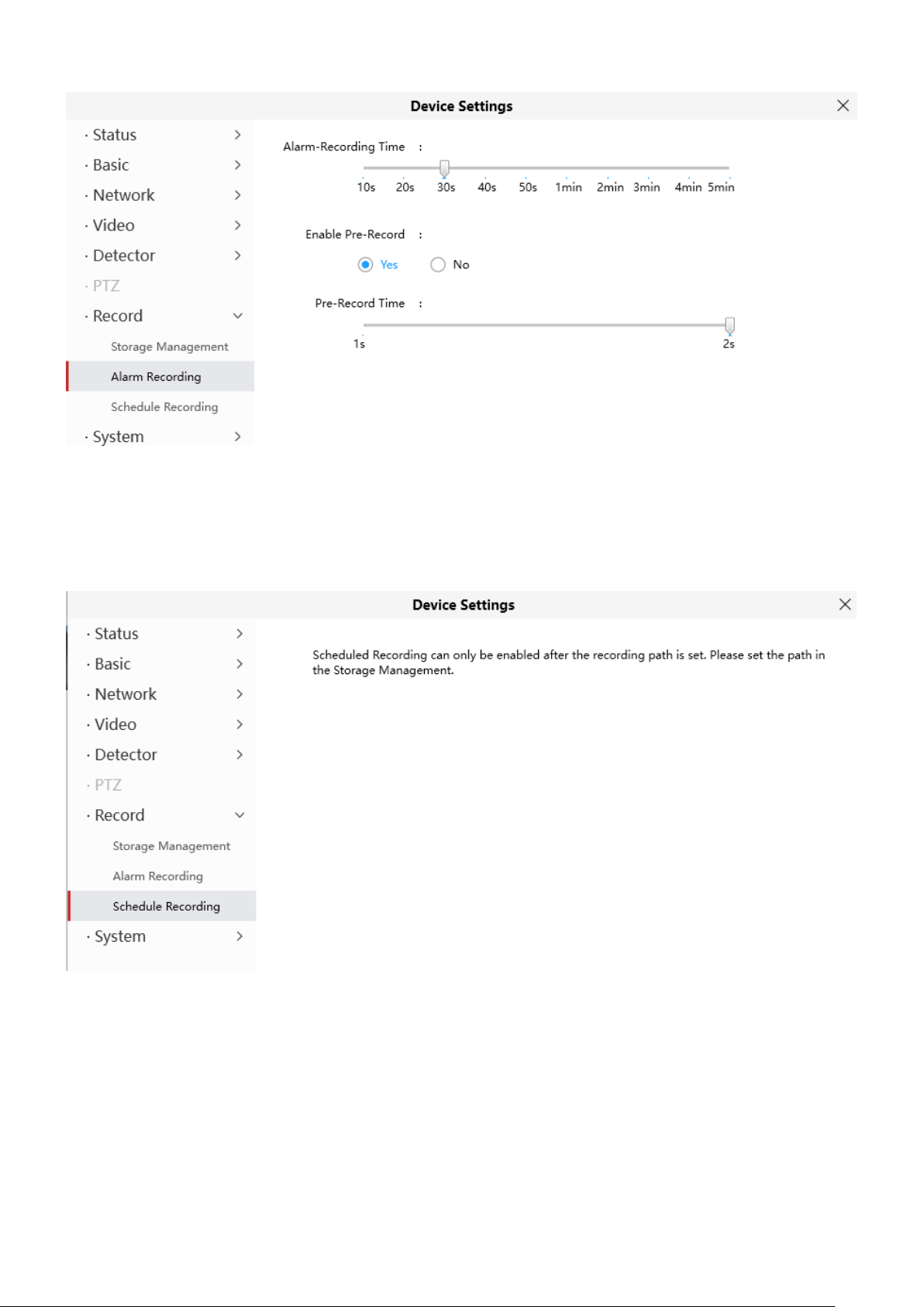
98
4.6.7.3 Schedule Recording
On the page you can configure the schedule record.
Note: Schedule Recording only supports FTP server. Schedule Recording can only be enabled after the
recording path is set Please set the path in the storage management.
Click Save button to take effect.
4.6.8 System
In this panel, you can back up/restore your camera settings, upgrade the firmware to the latest version, restore
the camera to default settings and reboot the device.
 Loading...