

Page 1
U
U
s
s
e
err
M
M
a
a
n
n
u
u
a
all
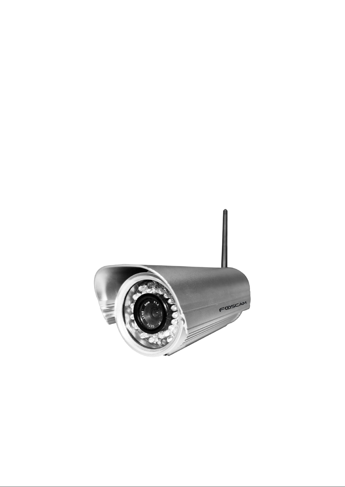
Outdoor HD Wireless IP Camera
Model: FI9801W
Page 2

1
wwwwww..ffoossccaamm..ccoomm
SShheennzzhheenn FFoossccaamm IInntteelllliiggeenntt TTeecchhnnoollooggyy CCoo..,, LLiimmiitteedd
TTeell:: 8866 775555 22667744 55666688 FFaaxx:: 8866 775555 22667744 55116688
1
Table of Contents
1 Overviews .......................................................................................................................................................... 2
1.1 Key Features .............................................................................................................................................. 3
1.2 Read Before Use ........................................................................................................................................ 3
1.3 Packing Contents ....................................................................................................................................... 3
1.4 Physical Description ................................................................................................................................... 4
2 Surveillance Software GUI ................................................................................................................................ 6
2.1 Login Window ............................................................................................................................................. 6
2.2 Surveillance Window .................................................................................................................................. 8
3 Advanced Camera Settings ............................................................................................................................ 14
3.1 Device Status ............................................................................................................................................ 14
3.1.1 Device Information ............................................................................................................................. 14
3.1.2 Device Status ..................................................................................................................................... 15
3.1.3 Session status .................................................................................................................................... 15
3.1.4 Log ..................................................................................................................................................... 16
3.2 Basic Settings ........................................................................................................................................... 17
3.2.1 Camera Name .................................................................................................................................... 17
3.2.2 Camera Time ..................................................................................................................................... 17
3.2.3 Mail Settings ...................................................................................................................................... 18
3.2.4 User Accounts .................................................................................................................................... 20
3.2.5 Multi-Camera ..................................................................................................................................... 22
3.3 Network ..................................................................................................................................................... 27
3.3.1 IP Configuration ................................................................................................................................. 27
3.3.2 PPPOE ............................................................................................................................................... 29
3.3.3 DDNS ................................................................................................................................................. 29
3.3.4 WiFi .................................................................................................................................................... 34
3.3.5 UPnP .................................................................................................................................................. 36
3.3.6 Port ..................................................................................................................................................... 36
3.4 Video ......................................................................................................................................................... 39
3.4.1 Settings .............................................................................................................................................. 39
3.4.2 On Screen Display ............................................................................................................................. 40
3.4.3 Snapshot Settings .............................................................................................................................. 41
3.5 Alarm ........................................................................................................................................................ 42
3.6 Record ....................................................................................................................................................... 46
3.7 Path Settings ............................................................................................................................................. 46
3.8 Firewall ..................................................................................................................................................... 48
3.9 System ...................................................................................................................................................... 49
Page 3

2
wwwwww..ffoossccaamm..ccoomm
SShheennzzhheenn FFoossccaamm IInntteelllliiggeenntt TTeecchhnnoollooggyy CCoo..,, LLiimmiitteedd
TTeell:: 8866 775555 22667744 55666688 FFaaxx:: 8866 775555 22667744 55116688
2
11 OOvveerrvviieewwss
3.9.1 Back up& Restore settings............................................................................................................... 49
3.9.2 System upgrade ............................................................................................................................... 49
3.9.3 Factory Reset ................................................................................................................................... 51
3.9.4 Reboot System .................................................................................................................................. 51
4 APPENDIX ...................................................................................................................................................... 52
4.1 Frequently Asked Questions .................................................................................................................... 52
4.2 Default Parameters ................................................................................................................................... 58
4.3 Specification .............................................................................................................................................. 58
5 OBTAINING TECHNICAL SUPPORT ............................................................................................................ 59
FOSCAM FI9801W is an integrated wireless IP Camera with a color CMOS sensor enabling
viewing resolution 1280*720. It combines a high quality digital video camera, with a powerful web
server, to bring clear video to your desktop from anywhere on your local network or over the
Internet.
FI9801W supports the industry-standard H.264 compression technology, drastically reducing file
sizes and conserving valuable network bandwidth.
The IPCAM is based on the TCP/IP standard. There is a WEB server inside which could support
Internet Explore. Therefore the management and maintenance of your device is simplified by
using the network to achieve the remote configuration and start-up.
The camera is designed for outdoor surveillance applications such as courtyards, supermarket,
and school. Controlling the IPCAM and managing images are simplified by using the provided
web interface across the network utilizing wireless connectivity.
Page 4
3
wwwwww..ffoossccaamm..ccoomm
SShheennzzhheenn FFoossccaamm IInntteelllliiggeenntt TTeecchhnnoollooggyy CCoo..,, LLiimmiitteedd
TTeell:: 8866 775555 22667744 55666688 FFaaxx:: 8866 775555 22667744 55116688
3
11..11 KKeeyy FFeeaattuurreess
11..22 RReeaadd BBeeffoorree UUssee
11..33 PPaacckkiinngg CCoonntteenntts
s
● IPCAM×1
● CD×1
● Wi-Fi Antenna×1 (only available for wireless
model)
● Quick Installation Guide ×1
● DC Power Supply×1
● Warranty Card×1
● Mounting bracket×1(option)
● Network Cable×1
Standard H.264 video compression algorithm to satisfy the transmission of high definition
video in narrow bandwidth network
1.0 Mega-Pixel
Supports IE/Firefox/Google/Safari browser or any other standard browsers
Supports WEP,WPA and WPA2 Encryption
Wi-Fi compliant with wireless standards IEEE 802.11b/g/n
IR night vision (Range:30m)
Supports image snapshot
Supports dual-stream
Supports IR-Cut and the filter change automatically
Embedded FOSCAM DDNS(dynamic domain name service) Service
Supports remote viewing & record from anywhere anytime
Multi-level users management with password protection
Motion detection alert via email or upload image to FTP
Supporting Third Party Domain name
Supports multiple network protocols: HTTP /TCP /IP /UDP /FTP /DHCP /DDNS / UPNP
Please first verify that all contents received are complete according to the Package Contents
listed below. Before the Network Camera is installed, please carefully read and follow the
instructions in the Quick Installation Guide to avoid damage due to faulty assembly and
installation. This also ensures the product is used properly as intended.
Page 5
4
wwwwww..ffoossccaamm..ccoomm
SShheennzzhheenn FFoossccaamm IInntteelllliiggeenntt TTeecchhnnoollooggyy CCoo..,, LLiimmiitteedd
TTeell:: 8866 775555 22667744 55666688 FFaaxx:: 8866 775555 22667744 55116688
4
11..44 PPhhyyssiiccaall DDeessccrriippttiioonn
1 2 3
4
5
1
2
3
4
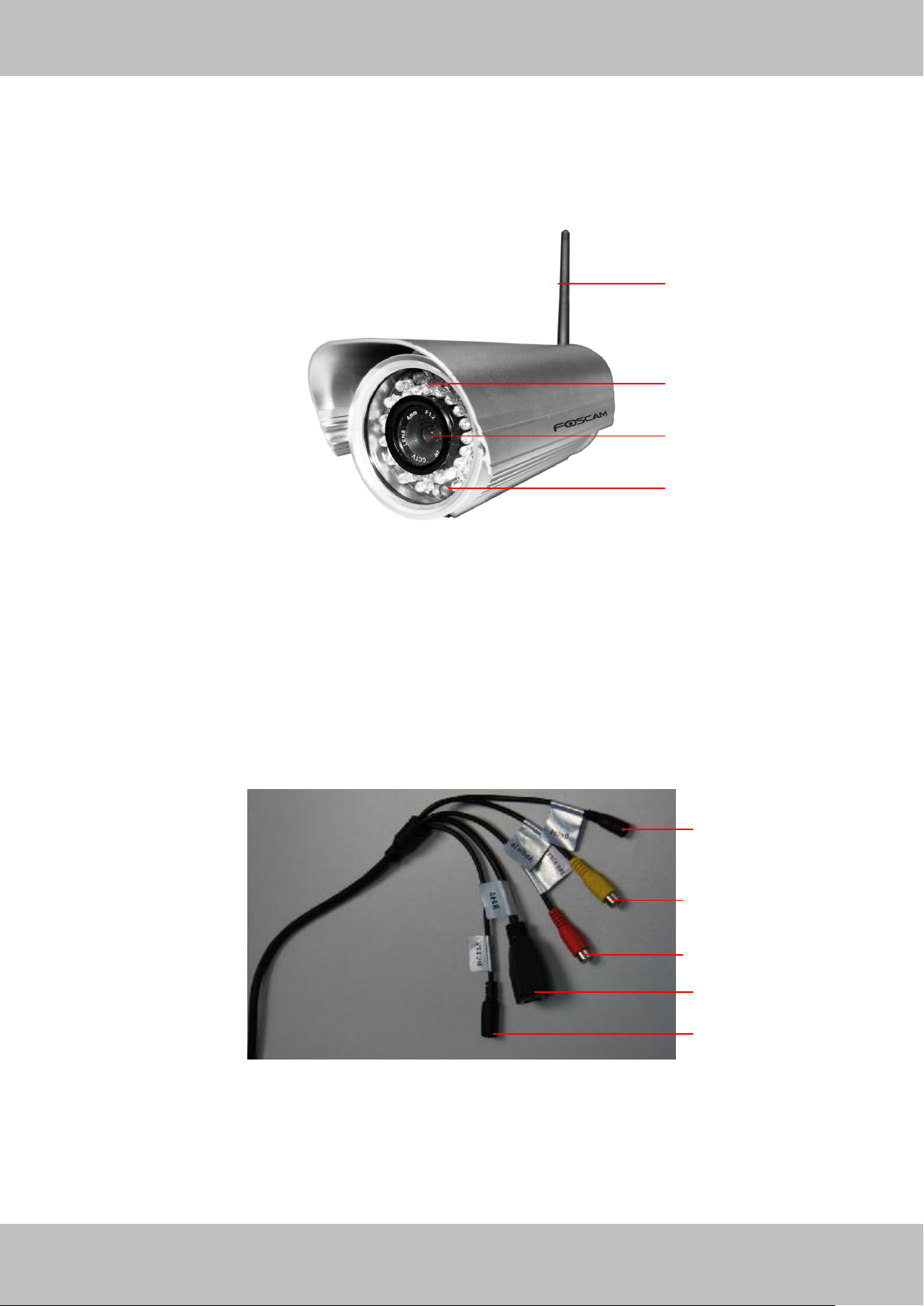
Front Panel
1 WIFI Antenna: Wireless Antenna
Figure 1.1
2 Infrared LED: 36 IR LEDs
3 LENS: CMOS sensor with fixed focus lens
4 Induction IC
Interface
Figure 1.2
1) Reset button : Press and hold on the reset button for 5 seconds. Releasing the reset
button, the password will back to the factory default administrator password. The default
administrator user is admin with no password.
Page 6
5
wwwwww..ffoossccaamm..ccoomm
SShheennzzhheenn FFoossccaamm IInntteelllliiggeenntt TTeecchhnnoollooggyy CCoo..,, LLiimmiitteedd
TTeell:: 8866 775555 22667744 55666688 FFaaxx:: 8866 775555 22667744 55116688
5
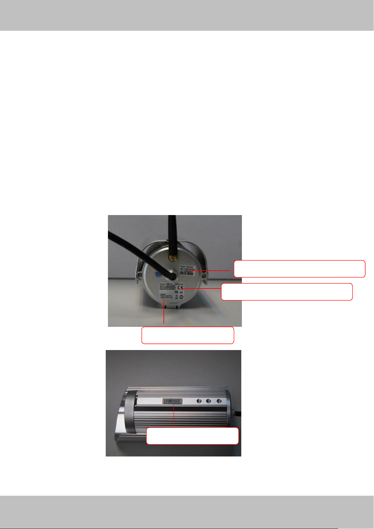
MAC address of wireless connection
MAC address of wired connection
FOSCAM DDNS Service
S/N Sticker of FOSCAM
2) Audio input interface: The jack is used to plug external microphone.
3) Audio output interface: The jack is used to plug external speakers.
4)LAN: 10/100M adaptive Ethernet interface. Through this interface, IPCAM can be connected
with various network devices, such as hub, router, etc.
5)Power Interface: Connect the external power adapter, request for 12V/2A power.
Bottom View
There are up to three labels located at the bottom of the camera; this is an important feature of
original Foscam cameras. If your camera does not have labels as shown in Figure 1.3, it may be
a clone. Cloned Foscam cameras can not use original firmware and are not eligible for warranty
or technical services.
Figure 1.3
Page 7
6
wwwwww..ffoossccaamm..ccoomm
SShheennzzhheenn FFoossccaamm IInntteelllliiggeenntt TTeecchhnnoollooggyy CCoo..,, LLiimmiitteedd
TTeell:: 8866 775555 22667744 55666688 FFaaxx:: 8866 775555 22667744 55116688
6
22 SSuurrvveeiillllaannccee SSooffttwwaarree GGUUII
22..11 LLooggiinn WWiinnddooww
2
3
4 5 1
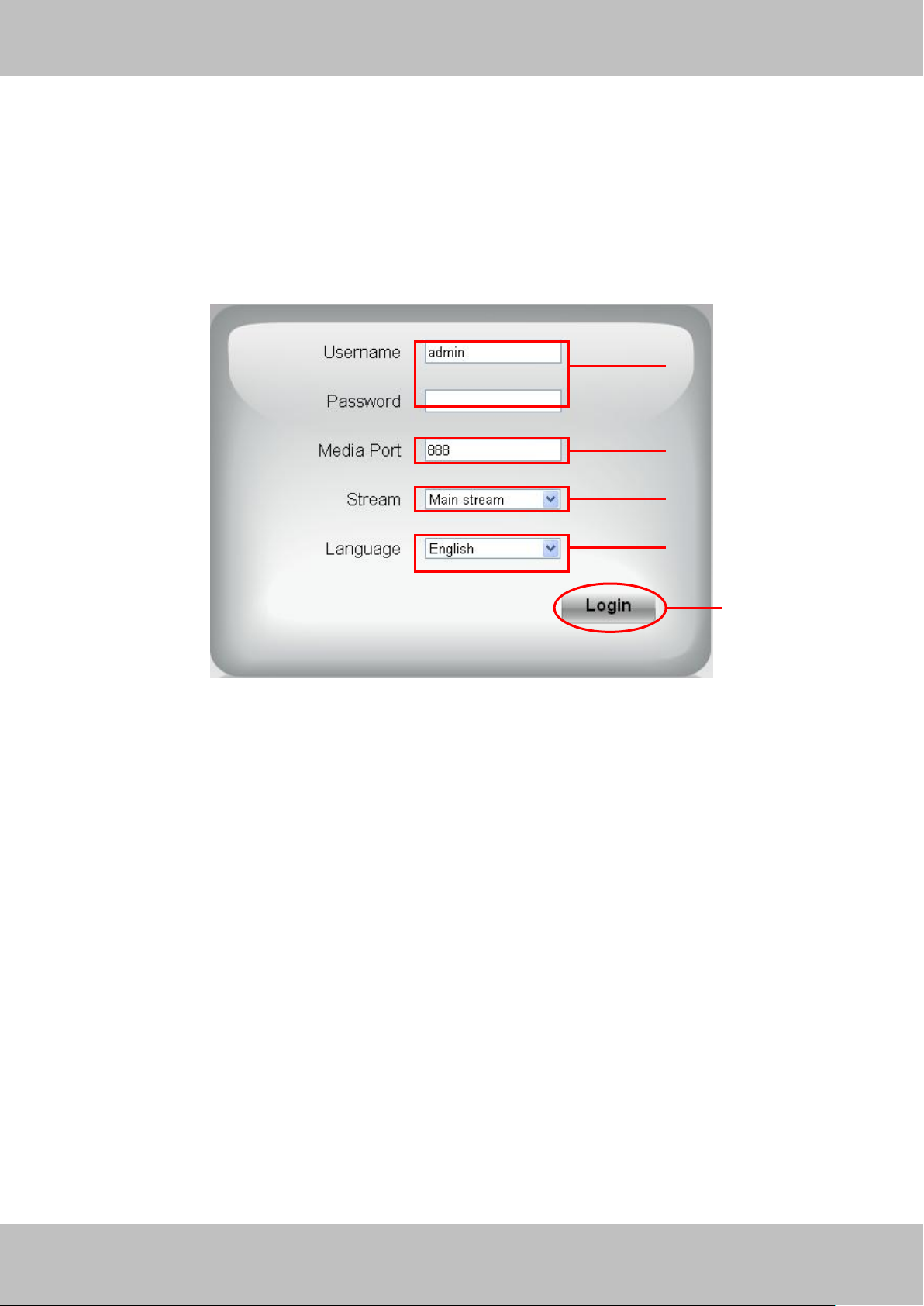
Please refer to the Quick Installation Guide if you install the camera at first time. After finishing
quick installation, you can take time to learn the operation of the software.
Figure 2.1
Please check the login window above, it was divided to 5 sections from no. 1 to 5.
Section1 Enter the User name and password
The default administrator username is admin with no password, please reset the password at
first using and prevent unauthorized users login the camera (read chapter 3.2.4 about how to
change).
Section2 Media port
The Media port is used to transfer video stream, and the default port no. is 888, you can reset the
port no. between 1 ~65535 on the Settings-NetworkPort page. The camera will obtain the
port no. automatically, you need not to fill it manually.
Section3 Stream
The camera supports two stream modes: Main stream and sub stream. If you want to access the
camera form LAN, here you can select Main stream. If you want to access the camera from
Internet, here we recommend sub stream.
Page 8
7
wwwwww..ffoossccaamm..ccoomm
SShheennzzhheenn FFoossccaamm IInntteelllliiggeenntt TTeecchhnnoollooggyy CCoo..,, LLiimmiitteedd
TTeell:: 8866 775555 22667744 55666688 FFaaxx:: 8866 775555 22667744 55116688
7
Note: When the network bandwidth is badly you’d better select Sub Stream and the video will be
more fluency.
Section4 Select the language
You can select the language you need via click on the language dropdown list to switch.
Section5 Login the camera
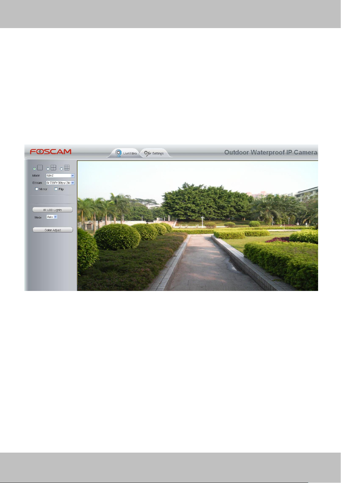
Click Login button and you will see the surveillance windows.
Figure 2.2
Page 9
8
wwwwww..ffoossccaamm..ccoomm
SShheennzzhheenn FFoossccaamm IInntteelllliiggeenntt TTeecchhnnoollooggyy CCoo..,, LLiimmiitteedd
TTeell:: 8866 775555 22667744 55666688 FFaaxx:: 8866 775555 22667744 55116688
8
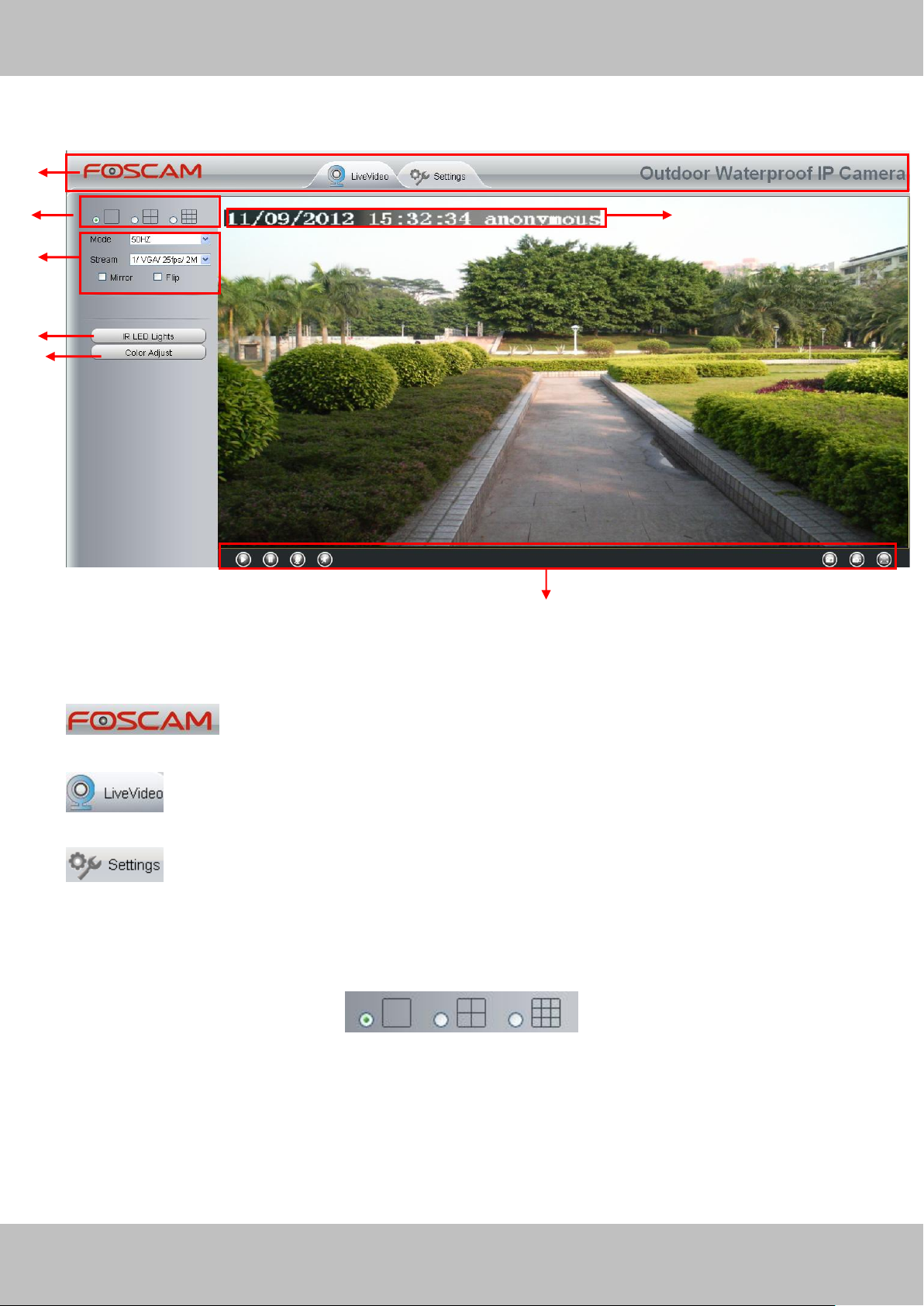
1 2 4 7 3 5 6
2.2 Surveillance Window
Figure 2.3
Section1 FOSCAM Logo/ LiveVideo / Settings buttons
: FOSCAM LOGO
: Path to surveillance window. Click this button and back to the surveillance window
: Path to Administrator Control Panel, Click it, and it will lead to Administrator
Control Panel and do advanced settings.
Section2 Multi-Device Window
The firmware inside the camera supports up to maximum of 9 cameras being monitoring at the
same time. You can add other cameras in multi-camera panel (read chapter 3.2.5).
Page 10
9
wwwwww..ffoossccaamm..ccoomm
SShheennzzhheenn FFoossccaamm IInntteelllliiggeenntt TTeecchhnnoollooggyy CCoo..,, LLiimmiitteedd
TTeell:: 8866 775555 22667744 55666688 FFaaxx:: 8866 775555 22667744 55116688
9
Figure 2.4
Section3 Mode/ Stream / Mirror/ Flip buttons
Mode
1) 50HZ ---------Indoor surveillance (Region: Europe, China)
2) 60HZ ---------Indoor surveillance (Region: USA, Canada)
Stream
The default Stream supports four modes: 0/720P/30fps/2M, 1/VGA/25fps/2M, 2/VGA/ 15fps/ 1M
and 3/ VGA/10fps/200 The format of the stream type is Stream type no. / Resolution /
Maximum frame rate/ Bit rate
1) Stream type no. : The number is used to identify the stream type.
2) 720P/ VGA
There are two resolutions, the bigger one is 720P, and the smaller one (VGA) is 640x480 pixels.
The bigger the resolution, the better of the image quality is. If you are accessing the camera via
internet and want to get more fluent video streaming, please select resolution VGA.
3) Maximum frame rate
When the video format is 50Hz, the maximum frame rate is 25 fps. When the video format is
60Hz, the maximum frame rate is 30 fps. You should lower frame rate when the bandwidth is
limited. Normally, when the frame rate above 15, you can achieve fluently video.
4) Bit rate
Generally speaking, the larger the bit rate is, the clearer video will become. But the bit rate
configuration should combine well with the network bandwidth. When the bandwidth is very
Page 11
10
wwwwww..ffoossccaamm..ccoomm
SShheennzzhheenn FFoossccaamm IInntteelllliiggeenntt TTeecchhnnoollooggyy CCoo..,, LLiimmiitteedd
TTeell:: 8866 775555 22667744 55666688 FFaaxx:: 8866 775555 22667744 55116688
10
narrow, and bit rate is large, that will lead to video cannot play well.
You can reset the stream type on Settings-> Video-> Settings panel( chapter 3.4.1).
After changing, please re-login the camera and you can see the modification.
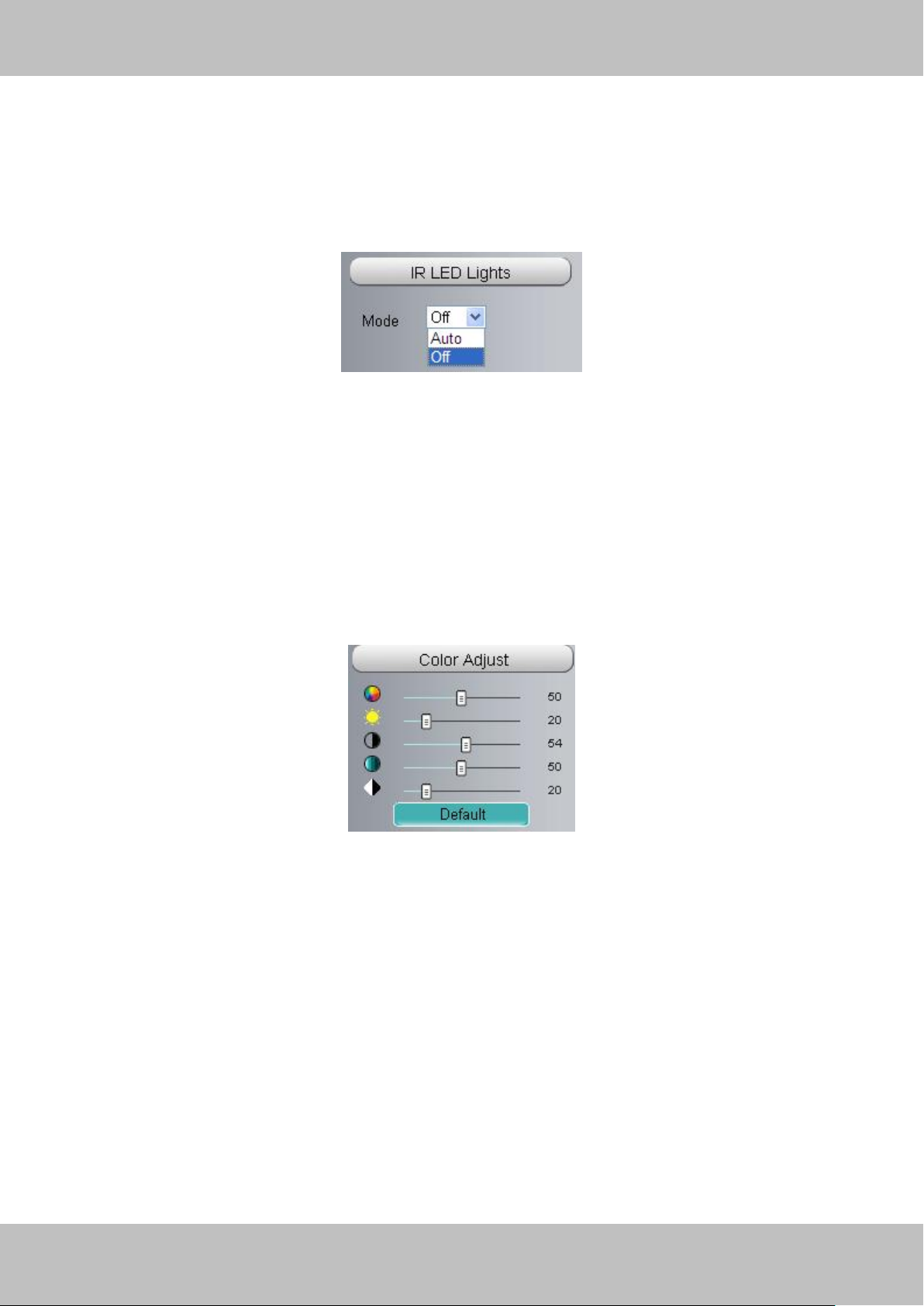
Section4 IR LED Lights
Click IR LED Lights and there are two modes to adjust the infrared led: Auto and Off . The default
mode is Auto.
Auto: Select it and the camera will adjust the infra led (on or off) automatically.
Off: Select it and turn off the infra led manually.
Section5 Image quality settings
In this page, you can tune Hue, Brightness, Contrast, Saturation, and Sharpness to get higher
quality.
Section6 OSD
If you have added time and camera name in the video, you can see it in the live window.
Go to Settings ---Basic settings---Camera name panel, and you can change another device
name. The default device name is anonymous.
Go to Settings ---Basic settings---Camera time panel and adjust the device time.
Go to Settings ---Video---On Screen Display panel, you can add or no add OSD.
Page 12
11
wwwwww..ffoossccaamm..ccoomm
SShheennzzhheenn FFoossccaamm IInntteelllliiggeenntt TTeecchhnnoollooggyy CCoo..,, LLiimmiitteedd
TTeell:: 8866 775555 22667744 55666688 FFaaxx:: 8866 775555 22667744 55116688
11
1 2 3
5 6 7
4
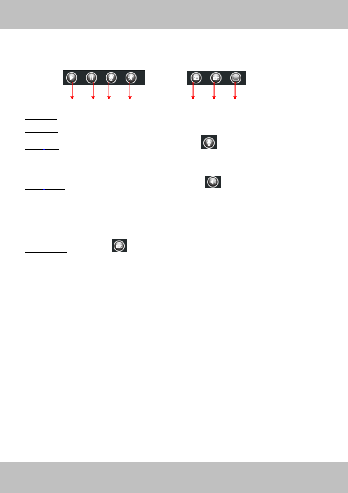
Section7 Play/Stop/ Talk/Audio/ Snap/ Record/ Full screen button
1------Play Click it to play the video of the camera
2------Stop Click it to stop the video of the camera
3------ Talk: Click the button and the icon will become to , then talk to the microphone that
connected with PC, people around the camera can hear your voice if the camera has connected
with audio output device. Click the icon again and stop talking.
4------ Audio Click the button and the icon will become to , you can hear the sound around
the camera if the camera has connected with other audio input device through the Audio Input
port of the camera, Click the icon again and stop audio.
5----- Snap: Click it to make snapshot and it pop up a window which picture you snapshot, right
click in the window and save the picture to anywhere you want.
6----- Record: Click the icon and the camera start recording, you can see a green dot in the
live window. Click again and stop recording. The default storage path is C:\IPCamRecord. You
can change the storage path: Go to Settings- >Record-> Storage Location panel.
7------Full Screen Click it to make full-screen, or you can double click the surveillance screen
to make full-screen. Double click again and exit full-screen.
Page 13
12
wwwwww..ffoossccaamm..ccoomm
SShheennzzhheenn FFoossccaamm IInntteelllliiggeenntt TTeecchhnnoollooggyy CCoo..,, LLiimmiitteedd
TTeell:: 8866 775555 22667744 55666688 FFaaxx:: 8866 775555 22667744 55116688
12
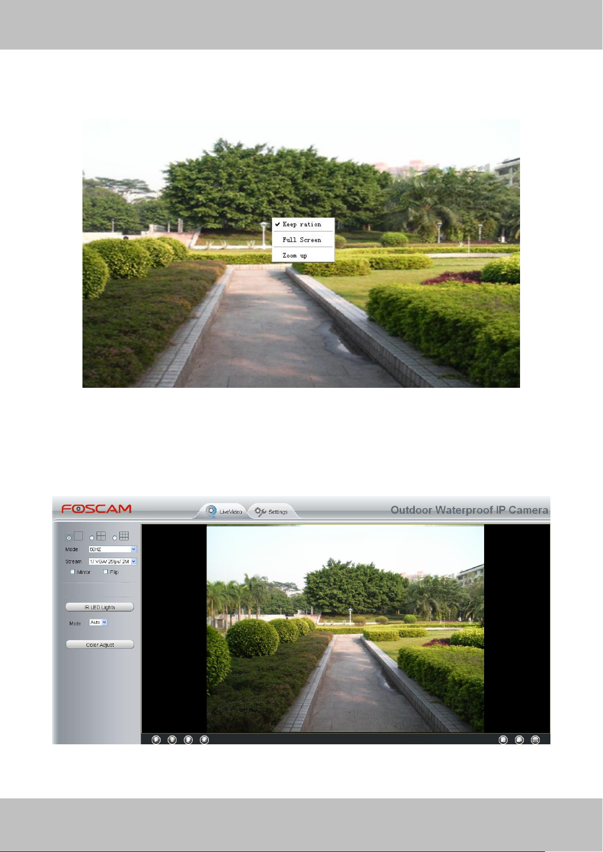
Onscreen Mouse Control
Right click the mouse and you can adjust the screen ration, full screen and Zoom up.
Figure 2.6
Keep ration: Select it and the camera will adjust the size of live window based on the computer
monitor automatically.
Sometimes there is a black border around the video (Figure 2.7), please select Keep ration to
get a better visual quality (Figure2.3).
Figure 2.7
Full Screen: Select it and Click it to make full-screen, press ESC and exit full-screen.
Page 14
13
wwwwww..ffoossccaamm..ccoomm
SShheennzzhheenn FFoossccaamm IInntteelllliiggeenntt TTeecchhnnoollooggyy CCoo..,, LLiimmiitteedd
TTeell:: 8866 775555 22667744 55666688 FFaaxx:: 8866 775555 22667744 55116688
13
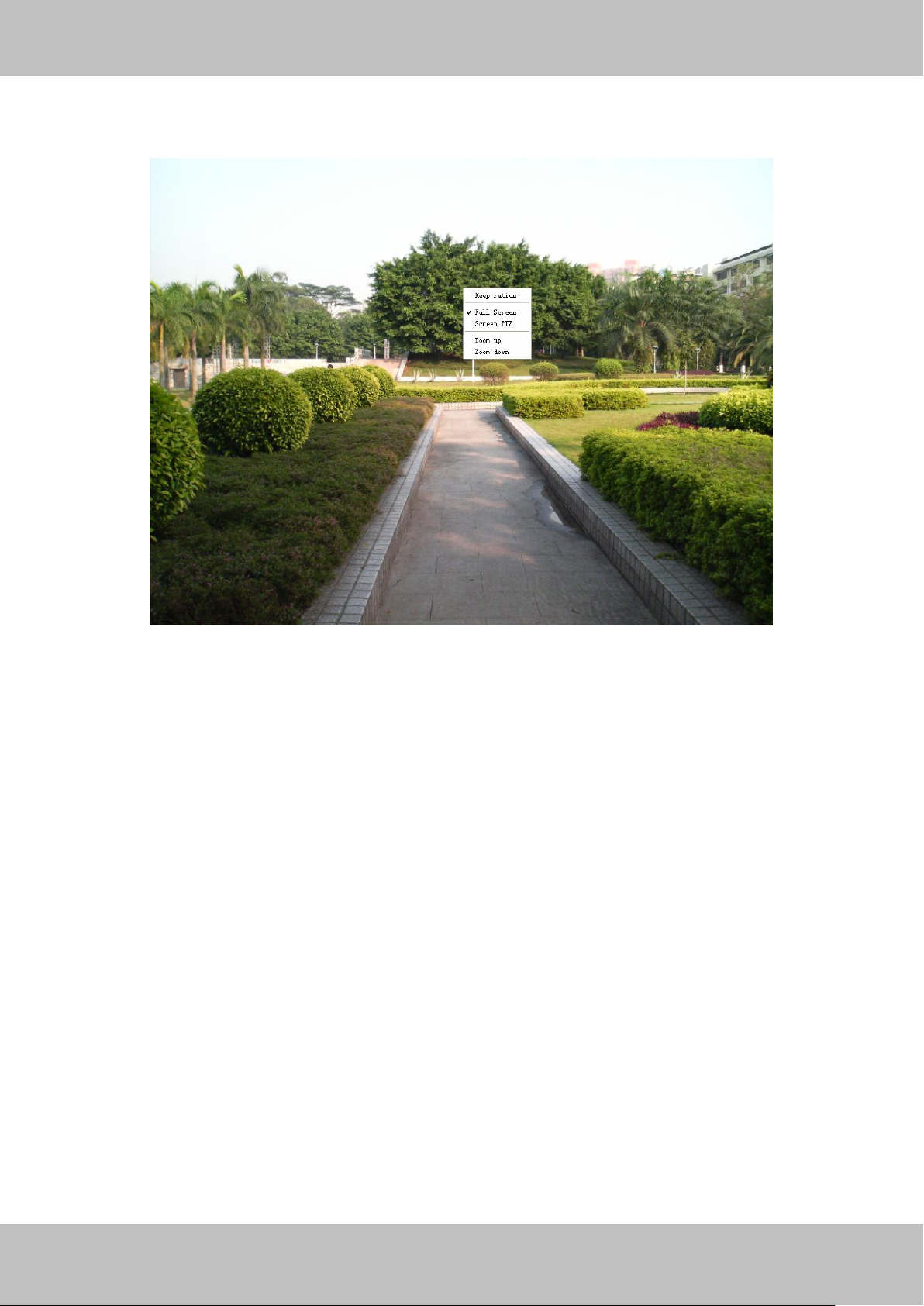
Zoom up/down: Click it and the live view will be digital zoomed up, then click Zoom Down and
the live view back to original size.
Figure 2.8
NOTE:
1 For this camera, it don’t have Pan/Tilt function, so here cannot allow to use Screen PTZ.
2 For MAC OS, the plugin cannot support Onscreen Mouse function, so you cannot allow to use
it.
Page 15
14
wwwwww..ffoossccaamm..ccoomm
SShheennzzhheenn FFoossccaamm IInntteelllliiggeenntt TTeecchhnnoollooggyy CCoo..,, LLiimmiitteedd
TTeell:: 8866 775555 22667744 55666688 FFaaxx:: 8866 775555 22667744 55116688
14
33 AAddvvaanncceedd CCaammeerraa SSeettttiinnggss
Click the button “Settings”, goes to Administrator Control Panel to make advanced camera
settings.
3.1 Device Status
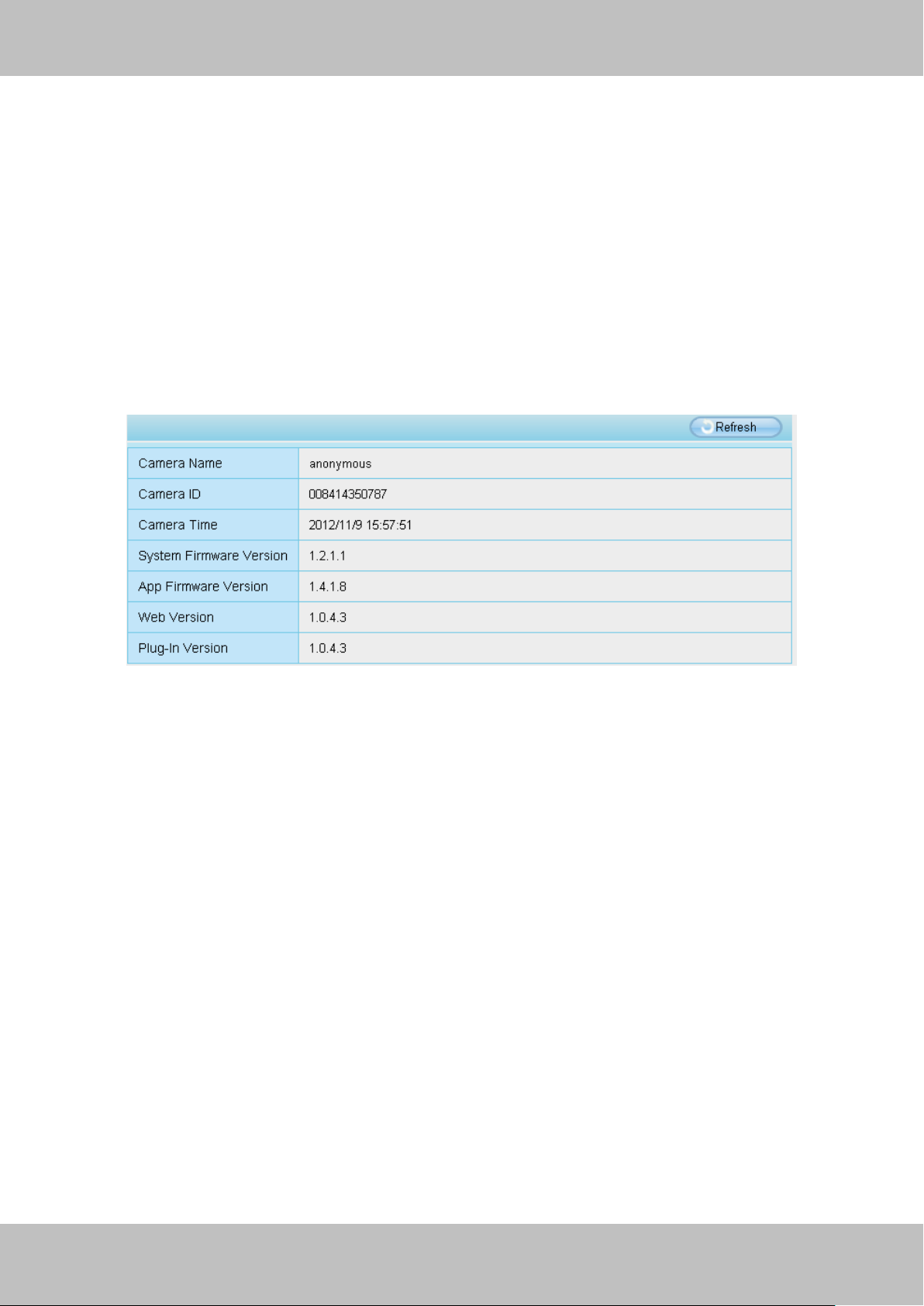
Device Status contains four columns: Device Information, Device Status, Session Status and
Log, it will show you various information about your camera.
3.1.1 Device Information
Figure 3.1
Device name: The Device Name is a unique name that you can give to your device to help you
identify it. Click Basic Settings and go to Device Name panel where you can change your camera
name. The default device name is anonymous.
Device ID: Display the MAC address of your camera. For example Device ID is 008414350787,
the same MAC ID sticker is found at the bottom of the camera.
Device time: The system time of the device. Click Basic Settings and go to Camera Time
panel and adjust the time.
System Firmware version: Display the System Firmware version of your camera.
App Firmware version: Display the application firmware version of your camera.
Web version: Display the web UI version of your camera
Plug-in version: Display the plug-in version of your camera
Page 16
15
wwwwww..ffoossccaamm..ccoomm
SShheennzzhheenn FFoossccaamm IInntteelllliiggeenntt TTeecchhnnoollooggyy CCoo..,, LLiimmiitteedd
TTeell:: 8866 775555 22667744 55666688 FFaaxx:: 8866 775555 22667744 55116688
15
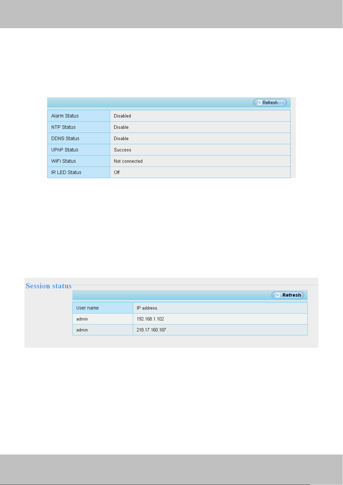
3.1.2 Device Status
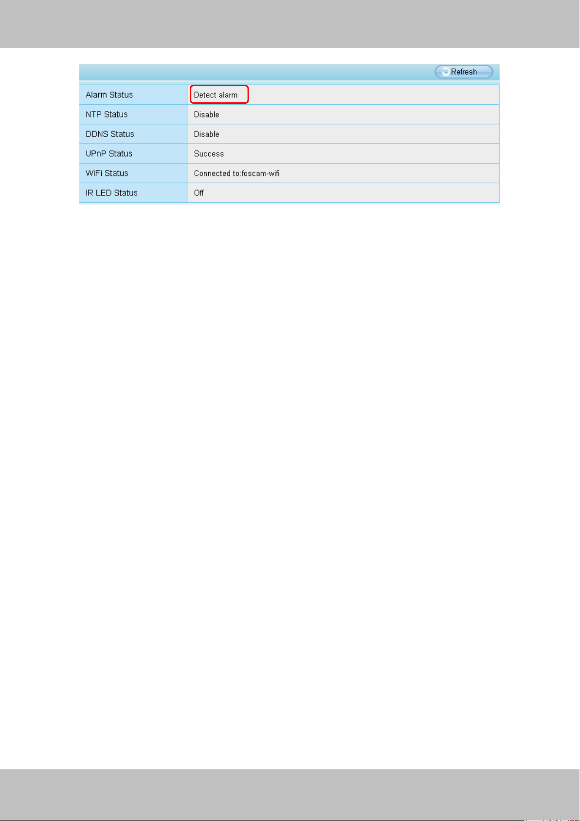
On this page you can see device status such as Alarm status, NTP/DDNS status, WIFI status
and so on.
Figure 3.2
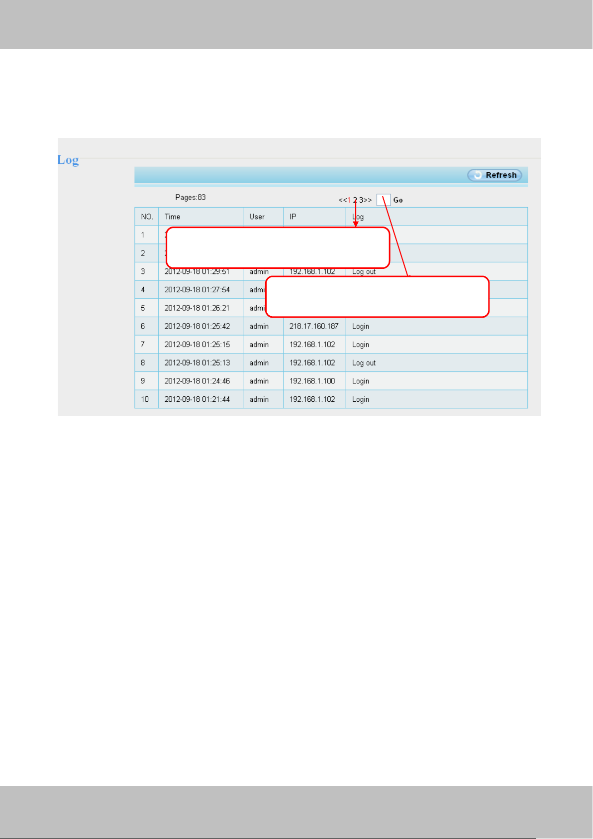
3.1.3 Session status
Session status will display who and which IP is visiting the camera now.
Figure 3.3
Page 17
16
wwwwww..ffoossccaamm..ccoomm
SShheennzzhheenn FFoossccaamm IInntteelllliiggeenntt TTeecchhnnoollooggyy CCoo..,, LLiimmiitteedd
TTeell:: 8866 775555 22667744 55666688 FFaaxx:: 8866 775555 22667744 55116688
16
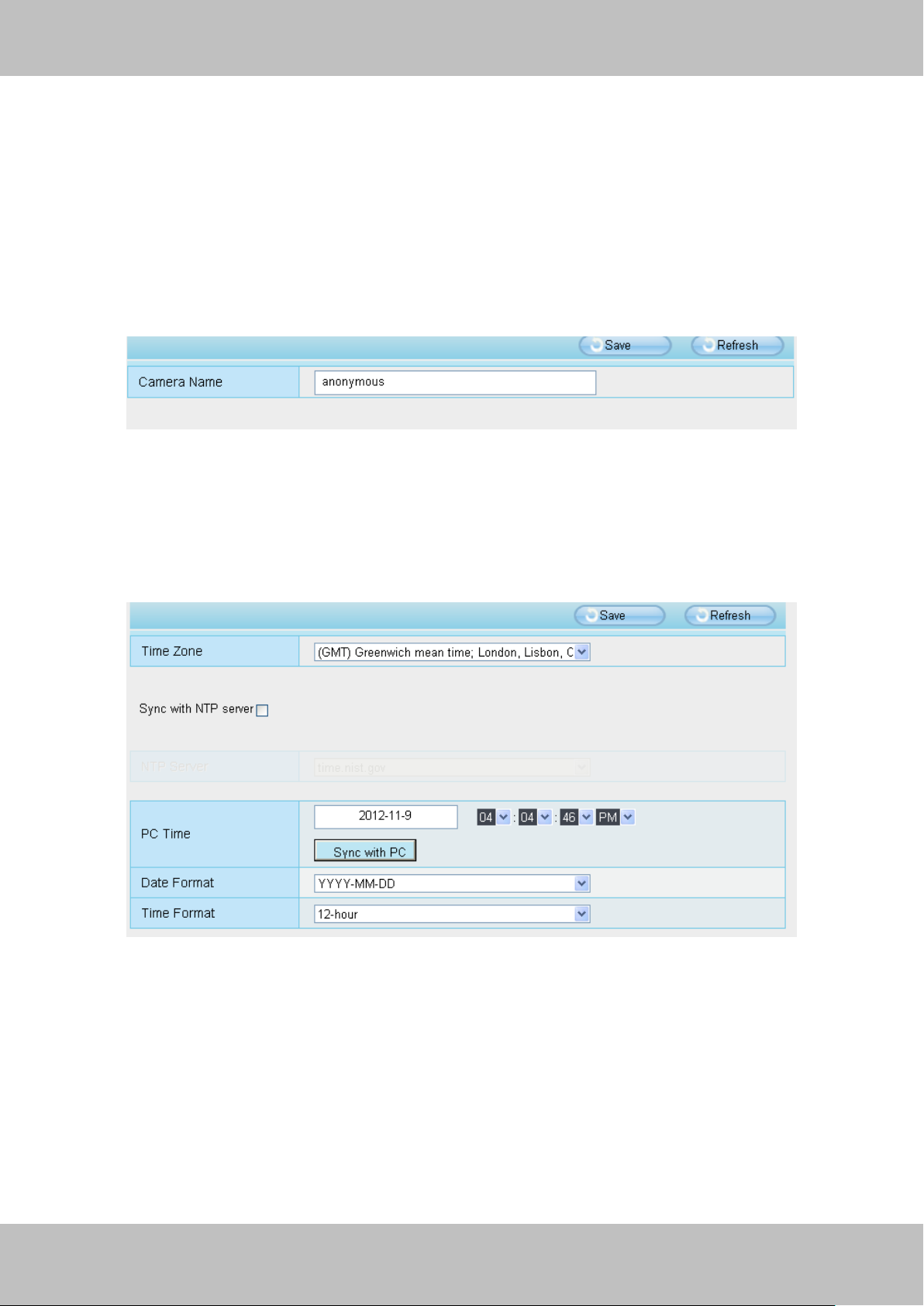
Click the page number and go to the
corresponding page to see more logs
Fill in one page number, click Go button
and go to the corresponding page
3.1.4 Log
The log record shows who and which IP address accessed or logout the camera and when.
Figure 3.4
Page 18
17
wwwwww..ffoossccaamm..ccoomm
SShheennzzhheenn FFoossccaamm IInntteelllliiggeenntt TTeecchhnnoollooggyy CCoo..,, LLiimmiitteedd
TTeell:: 8866 775555 22667744 55666688 FFaaxx:: 8866 775555 22667744 55116688
17
3.2 Basic Settings
This section allows you to configure your Camera Name, Camera Time, Mail, User Accounts and
Multi-Device.
3.2.1 Camera Name
Default alias is Anonymous. You can define a name for your camera here such as apple. Click
Save to save your changes. The alias name cannot contain special characters.
Figure 3.5
3.2.2 Camera Time
This section allows you to configure the settings of the internal system clocks for your camera.
Figure 3.6
Time Zone: Select the time zone for your region from the dropdown menu.
Sync with NTP server: Network Time Protocol will synchronize your camera with an Internet
time server. Choose the one that is closest to your camera.
Sync with PC: Select this option to synchronize the date and time of the Network Camera with
your computer.
Manually: The administrator can enter the date and time manually. Please select the date and
Page 19
18
wwwwww..ffoossccaamm..ccoomm
SShheennzzhheenn FFoossccaamm IInntteelllliiggeenntt TTeecchhnnoollooggyy CCoo..,, LLiimmiitteedd
TTeell:: 8866 775555 22667744 55666688 FFaaxx:: 8866 775555 22667744 55116688
18
1
2
3
4
5
6
time format.
Click Save button to submit your settings.
3.2.3 Mail Settings
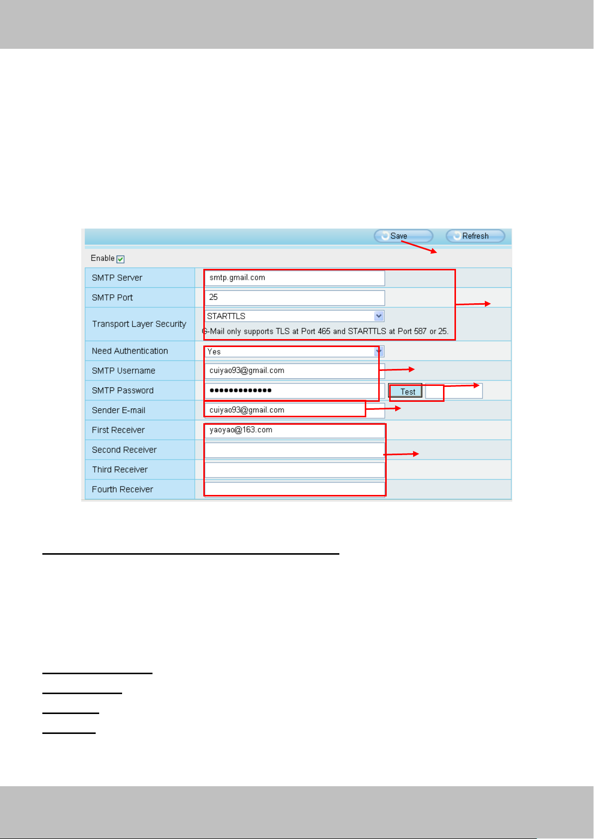
If you want the camera to send emails when motion has been detected, here Mail will need to be
configured.
Figure 3.7
1----- SMTP Server/ Port /Transport Layer Security Enter SMTP server for sender. SMTP
port is usually set as 25. Some SMTP servers have their own port, such as 587 or 465, and
Transport Layer Security usually is None. If you use Gmail, Transport Layer Security must be set
to TLS or STARTTLS and SMTP Port must be set to 465 or 25 or 587, which port you choose
should be decided by which Transport Layer Security you select.
2-----SMTP Username/ password: ID account and password of the sender email address
3----- Sender E-mail Mailbox for sender must support SMTP
4----- Receiver Mailbox for receiver need not support SMTP,you can set 4 receivers
5----Save Click Save to take effect
6----Test Click Test to see if Mail has been successfully configured.
Click Test to see if Mail has been successfully configured.
Page 20
19
wwwwww..ffoossccaamm..ccoomm
SShheennzzhheenn FFoossccaamm IInntteelllliiggeenntt TTeecchhnnoollooggyy CCoo..,, LLiimmiitteedd
TTeell:: 8866 775555 22667744 55666688 FFaaxx:: 8866 775555 22667744 55116688
19
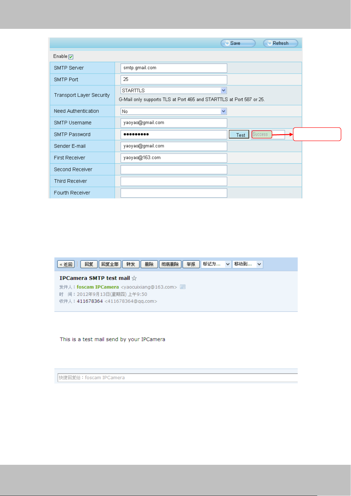
Test result
Figure 3.8
If the test success, you can see the Success behind the Test, at the same time the receivers will
receive a test mail.
Figure 3.9
If the test fails with one of the following errors after clicking Test, verify that the information you
entered is correct and again select Test .
1) Cannot connect to the server
2) Network Error. Please try later
3) Server Error
Page 21
20
wwwwww..ffoossccaamm..ccoomm
SShheennzzhheenn FFoossccaamm IInntteelllliiggeenntt TTeecchhnnoollooggyy CCoo..,, LLiimmiitteedd
TTeell:: 8866 775555 22667744 55666688 FFaaxx:: 8866 775555 22667744 55116688
20
4) Incorrect user or password
5) The sender is denied by the server. Maybe the server need to authenticate the user, please
check it and try again
6) The receiver is denied by the server. Maybe because of the anti-spam privacy of the server
7) The message is denied by the server. Maybe because of the anti-spam privacy of the server
8) The server does not support the authentication mode used by the device
3.2.4 User Accounts
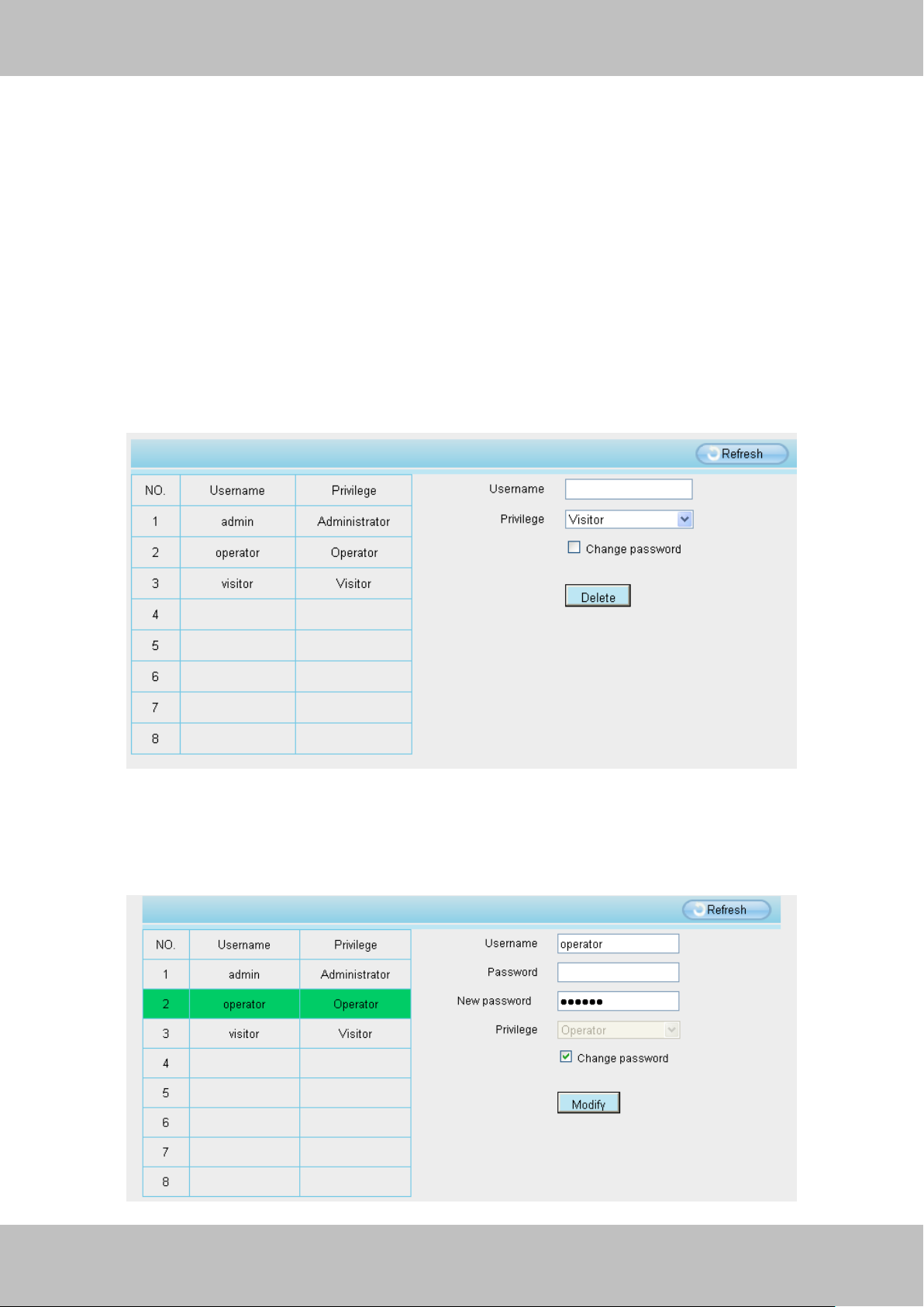
Here you can create users and set privilege, visitor, operator or administrator. The default
user accounts are admin, operator and visitor, with a blank password.
Figure 3.10
How to change the password?
Firstly, select the account which you want to change the password, then select “Change
password”, enter the old password and the new password, lastly click modify to take effect.
Page 22
21
wwwwww..ffoossccaamm..ccoomm
SShheennzzhheenn FFoossccaamm IInntteelllliiggeenntt TTeecchhnnoollooggyy CCoo..,, LLiimmiitteedd
TTeell:: 8866 775555 22667744 55666688 FFaaxx:: 8866 775555 22667744 55116688
21
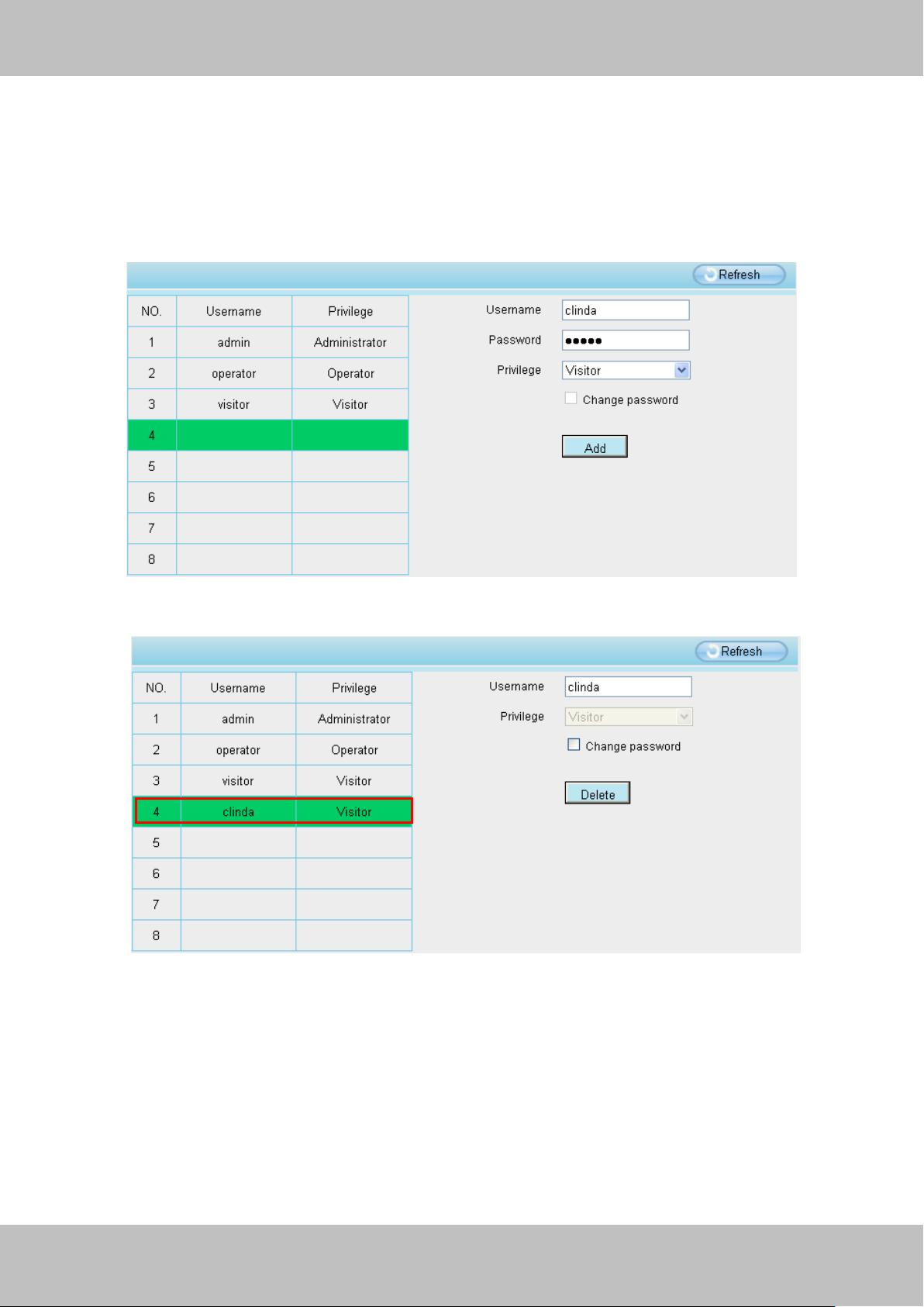
Figure 3.11
How to add account ?
Select one blank column, then enter the new user name, password and privilege, last click Add
to take effect. You can see the new added account on the Account list.
Figure 3.12
Figure 3.13
Delete Select the account which you want to delete, then click Delete button to take effect.
Note: The default administrator account cannot be deleted, but you can add other administrator
users.
Page 23
22
wwwwww..ffoossccaamm..ccoomm
SShheennzzhheenn FFoossccaamm IInntteelllliiggeenntt TTeecchhnnoollooggyy CCoo..,, LLiimmiitteedd
TTeell:: 8866 775555 22667744 55666688 FFaaxx:: 8866 775555 22667744 55116688
22
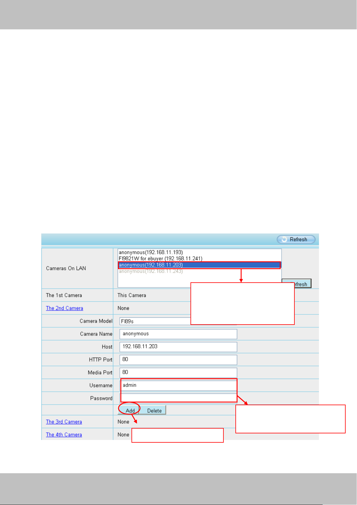
1 Click it, camera model, alias,
host and HTTP Port will be
filled in the following boxes
automatically
2 Enter the User name and
password of the 2nd camera
3 Click Add to take effect
3.2.5 Multi-Camera
If you want to view multi-surveillance screens on one window, you need to login one camera, and
set it as the main device, and do Multi-Device Settings, add other cameras to the first one
camera. Before you do multi-cams settings, you need to assign different port such as 81, 82, 83,
84, 85, 86, 87, 88 to the cameras if there is 8 cams installed.
The firmware within the camera can support a maximum of 9 devices monitoring all at the same
time. This page you can both add FOSCAM MJPEG and H.264 series cameras to the first
camera and view multi-surveillance screen on one window.
Add cameras in LAN
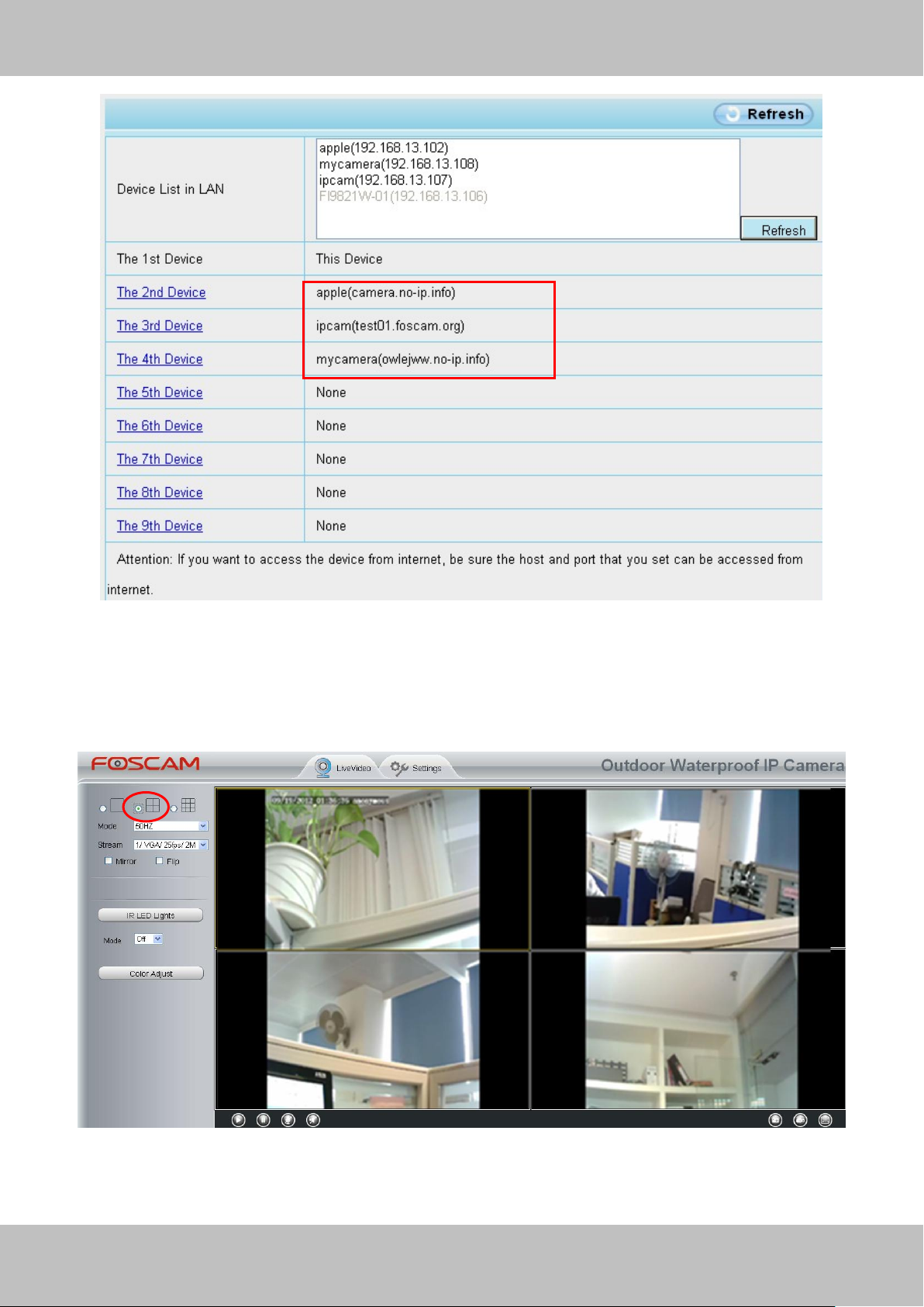
In Multi-Device Settings page, you can see all devices searched in LAN. The 1st Device is the
default one. You can add more cameras in the list in LAN for monitoring. The camera’s software
supports up to 9 IP Cameras online simultaneously. Click The 2nd Device and click the item in
the Device List in LAN, the Alias, Host and Http Port will be filled in the boxes below
automatically. Enter the correct username and password then click Add. Add more cameras in
the same way.
Figure 3.14
Page 24
23
wwwwww..ffoossccaamm..ccoomm
SShheennzzhheenn FFoossccaamm IInntteelllliiggeenntt TTeecchhnnoollooggyy CCoo..,, LLiimmiitteedd
TTeell:: 8866 775555 22667744 55666688 FFaaxx:: 8866 775555 22667744 55116688
23
Camera Model: Our Company produces two series cameras: MJPEG and H.264. All MJPEG
camera models will be named after FI89xx, and all H.264 camera models will be named after
FI98xx. Here will show you which series the camera belongs to.
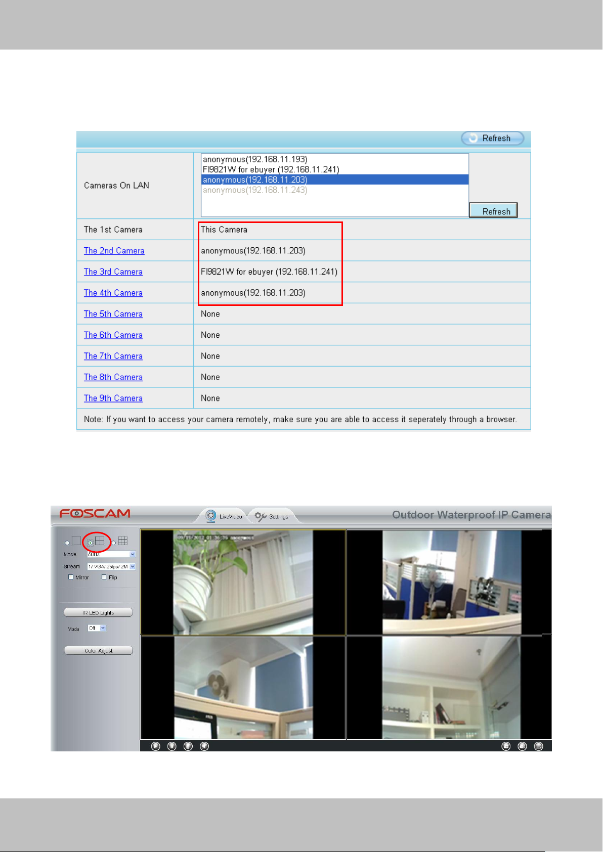
Figure 3.15
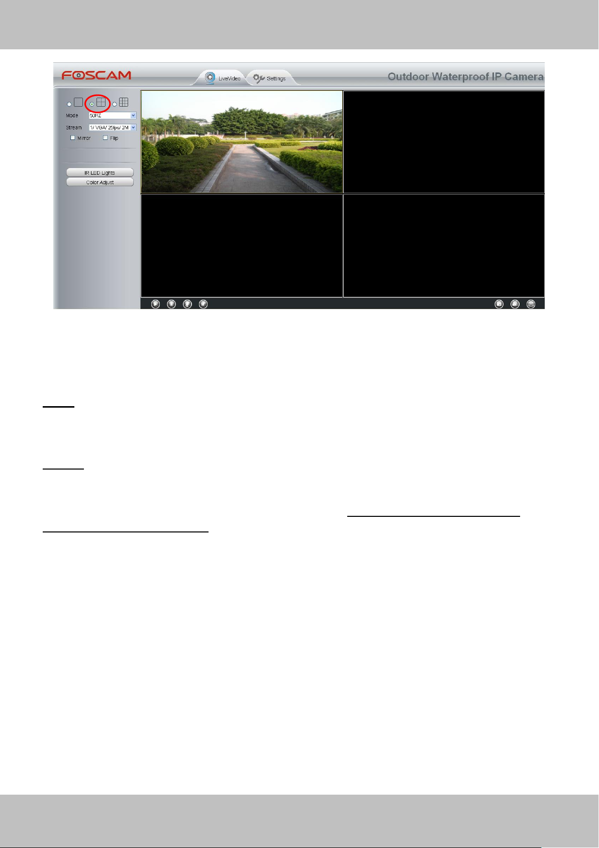
Back to Surveillance Windows, and click Four Windows option, you will see four cameras you
added.
Figure 3.16
Page 25
24
wwwwww..ffoossccaamm..ccoomm
SShheennzzhheenn FFoossccaamm IInntteelllliiggeenntt TTeecchhnnoollooggyy CCoo..,, LLiimmiitteedd
TTeell:: 8866 775555 22667744 55666688 FFaaxx:: 8866 775555 22667744 55116688
24
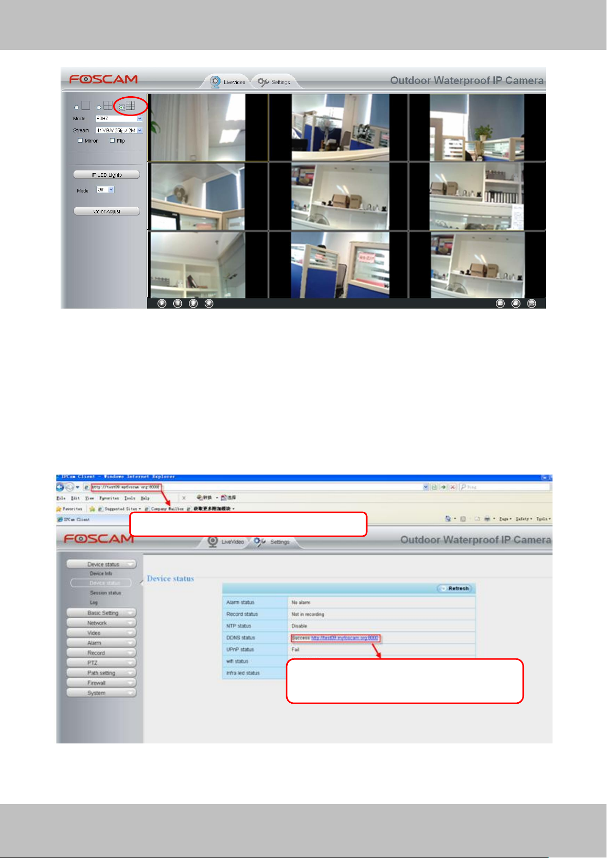
Use DDNS domain name and port to login
Make sure each camera you need add
could login with DDNS name and port
Figure 3.17
Add cameras in WAN
If you want to view all cameras via the internet(remote computer), you will need to add them
using DDNS domain name. Firstly, make sure all of the cameras you added can be accessed
through the internet. (Read How to configure DDNS settings in chapter 3.3.3)
Login to the first camera using a DDNS domain name and port.
Figure 3.18
Page 26
25
wwwwww..ffoossccaamm..ccoomm
SShheennzzhheenn FFoossccaamm IInntteelllliiggeenntt TTeecchhnnoollooggyy CCoo..,, LLiimmiitteedd
TTeell:: 8866 775555 22667744 55666688 FFaaxx:: 8866 775555 22667744 55116688
25
2
3
4
5
1
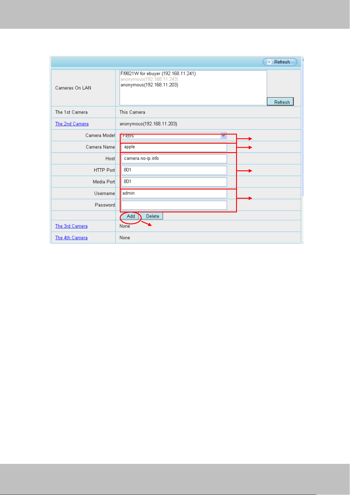
Click Multi-Device Settings. Choose The 2nd Device. Fill in the 2nd camera’s name, DDNS
domain name, port number. Enter user name and password and then choose Add. (Figure 3.19)
Figure 3.19
1----- The camera model: FI89s or FI98s.
2----- The 2nd camera’s name
3----- Fill in the 2nd camera’s DDNS host not LAN IP
NOTE: The FI89s series have the same HTTP Port no. and Media Port no.
4 ---- Enter the 2nd camera’s user name and password
5---- Click Add button and to take effect
NOTE: Here the Host must be entered as the second camera’s DDNS domain name, not its LAN
IP.
Page 27
26
wwwwww..ffoossccaamm..ccoomm
SShheennzzhheenn FFoossccaamm IInntteelllliiggeenntt TTeecchhnnoollooggyy CCoo..,, LLiimmiitteedd
TTeell:: 8866 775555 22667744 55666688 FFaaxx:: 8866 775555 22667744 55116688
26
Figure 3.20
Return to video window. You will see all of the cameras accessible through the internet.
When you are away from home, you can use the first camera’s DDNS domain name and port to
view all the cameras via internet.
Figure 3.21
Page 28
27
wwwwww..ffoossccaamm..ccoomm
SShheennzzhheenn FFoossccaamm IInntteelllliiggeenntt TTeecchhnnoollooggyy CCoo..,, LLiimmiitteedd
TTeell:: 8866 775555 22667744 55666688 FFaaxx:: 8866 775555 22667744 55116688
27
33..33 NNeettwwoorrkk
This section will allow you to configure your camera’s IP, PPOE, DDNS, Wireless Settings, UPnP
and Port.
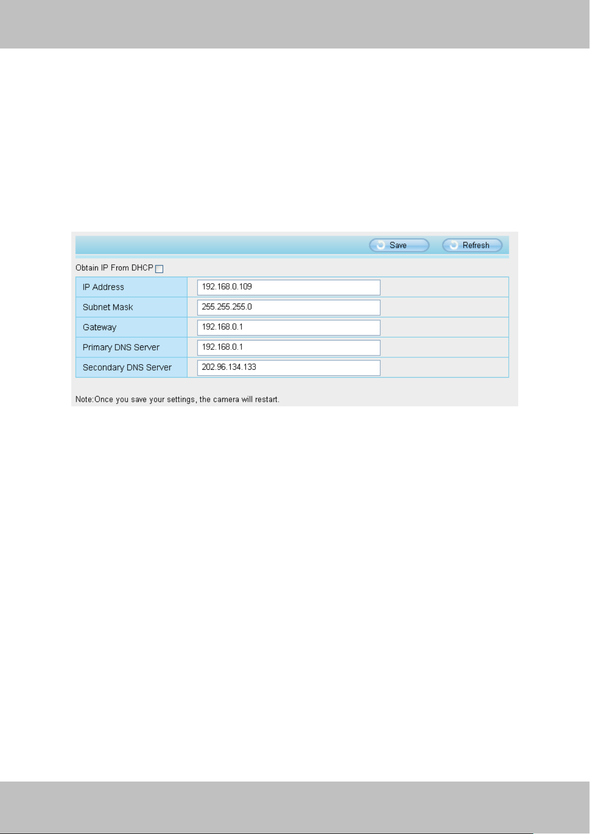
3.3.1 IP Configuration
If you want to set a static IP for the camera, please go to IP Configuration page. Keep the
camera in the same subnet of your router or computer.
Figure 3.22
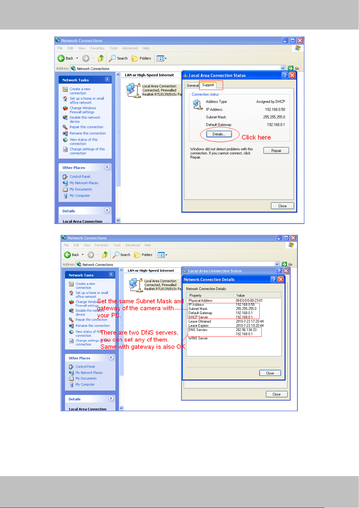
Changing settings here is the same as using the IP Camera Tool. (Figure 3.23/3.24)
It is recommended that you use the subnet mask, gateway and DNS server from your locally
attached PC. If you don’t know the subnet mask, gateway and DNS server, you can check your
computer’s local area connection as follows:
Control PanelNetwork ConnectionsLocal Area Connections Choose
SupportDetails.
Page 29
28
wwwwww..ffoossccaamm..ccoomm
SShheennzzhheenn FFoossccaamm IInntteelllliiggeenntt TTeecchhnnoollooggyy CCoo..,, LLiimmiitteedd
TTeell:: 8866 775555 22667744 55666688 FFaaxx:: 8866 775555 22667744 55116688
28
Figure 3.23
Figure 3.24
If you don’t know the DNS server, you can use the same settings as the Default Gateway.
Page 30
29
wwwwww..ffoossccaamm..ccoomm
SShheennzzhheenn FFoossccaamm IInntteelllliiggeenntt TTeecchhnnoollooggyy CCoo..,, LLiimmiitteedd
TTeell:: 8866 775555 22667744 55666688 FFaaxx:: 8866 775555 22667744 55116688
29
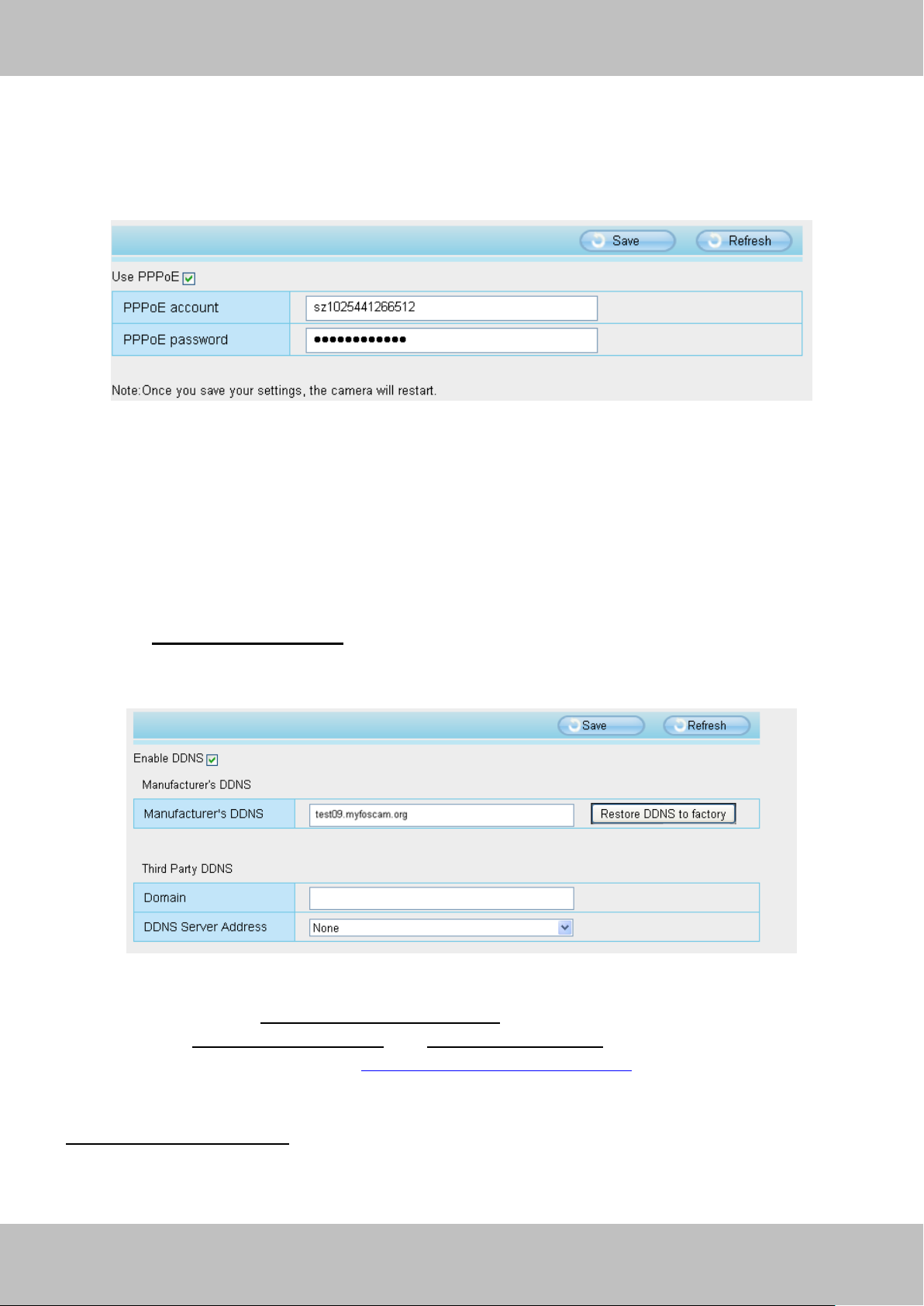
3.3.2 PPPOE
If you are using a PPPoE connection, enable it and enter the User Name and Password for your
PPPoE account.
Figure 3.25
3.3.3 DDNS
FOSCAM camera has embedded a unique DDNS domain name when producing, and you can
directly use the domain name, you can also use the third party domain name.
FOSCAM domain name
Here take test09.myfoscam.org for example. Go to option of DDNS on the Settings->Network
panel, you can see the domain name.
Figure 3.26
Now you can use http:// Domain name + HTTP Port to access the camera via internet.
Take hostname test09.myfoscam.org and HTTP Port no. 8000 for example, the accessing link
of the camera via internet would be http:// test09.myfoscam.org:8000
Restore DDNS to factory: If you have configured Third Party DDNS successfully, but you want
to use Manufacturer’s DDNS again , here click this button and start Manufacturer’s DDNS
Service.
Page 31

30
wwwwww..ffoossccaamm..ccoomm
SShheennzzhheenn FFoossccaamm IInntteelllliiggeenntt TTeecchhnnoollooggyy CCoo..,, LLiimmiitteedd
TTeell:: 8866 775555 22667744 55666688 FFaaxx:: 8866 775555 22667744 55116688
30
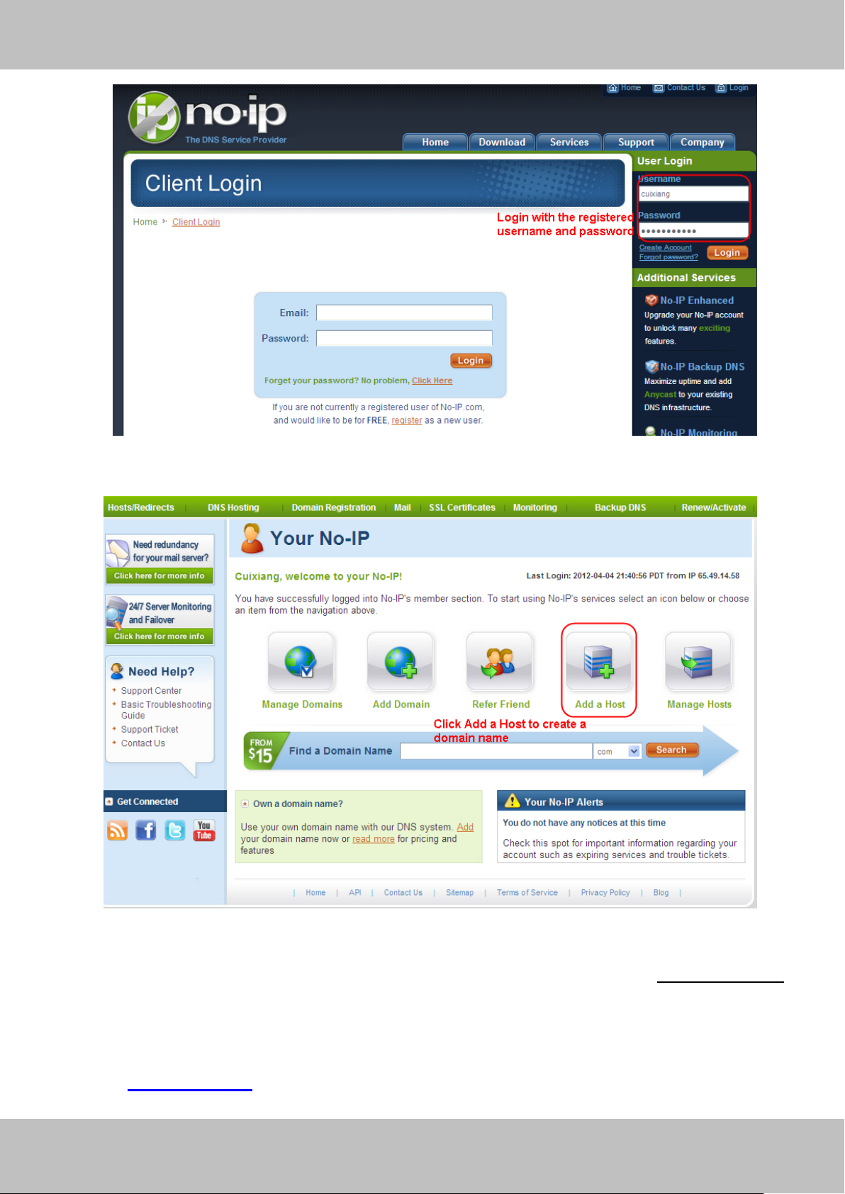
Click here to register
Third Party Domain Name Settings
User can also use third part DDNS, such as www.no-ip.com. ,www. 3322.com
Here take www.no-ip.com for example:
① Step 1, Go to the website www.no-ip.com to create a free hostname
Firstly: Login on www.no-ip.com and click No-IP Free to register.
Figure 3.27
Please register an account step by step according to instructions on www.no-ip.com
After registration, please login your email which used to register. You will receive an email from
website, please click the link to activate your ACCOUNT as indicated in email.
Secondly: Login the link with the registered username and password to create your
domain name.
Page 32
31
wwwwww..ffoossccaamm..ccoomm
SShheennzzhheenn FFoossccaamm IInntteelllliiggeenntt TTeecchhnnoollooggyy CCoo..,, LLiimmiitteedd
TTeell:: 8866 775555 22667744 55666688 FFaaxx:: 8866 775555 22667744 55116688
31
Figure 3.28
Figure 3.29
Please create the domain name step by step according to instructions on www.no-ip.com
Step 2, DO DDNS Service Settings within the Camera
Please set DDNS Settings within the camera by hostname, a user name and password you’ve
got from www.no-ip.com
Page 33

32
wwwwww..ffoossccaamm..ccoomm
SShheennzzhheenn FFoossccaamm IInntteelllliiggeenntt TTeecchhnnoollooggyy CCoo..,, LLiimmiitteedd
TTeell:: 8866 775555 22667744 55666688 FFaaxx:: 8866 775555 22667744 55116688
32
Note
Take hostname ycxgwp.no-ip.info, user name foscam, password foscam2012 for example.
Firstly, goes to option of DDNS Settings on the administrator panel.
Secondly, select No-Ip as a server..
Thirdly, fill foscam as DDNS user, fill password foscam2012 as DDNS password, fill
ycxgwp.no-ip.info as DDNS domain and server URL, Then click save to make effect. The
camera will restart and to take the DDNS settings effective.
Fourthly, after the restart, login the camera, and go to option of Device Status on the
administrator panel, and check if the DDNS status is successful.
If failed, please double check if you have input the correct hostname, user name, and
password, and try to redo the settings.
If you have set Third Party DDNS successfully ,the Foscam Domain Name will be invalid. The
Third Party DDNS and the Foscam Domain Name cannot work at the same time, the last time
you configured will take effect.
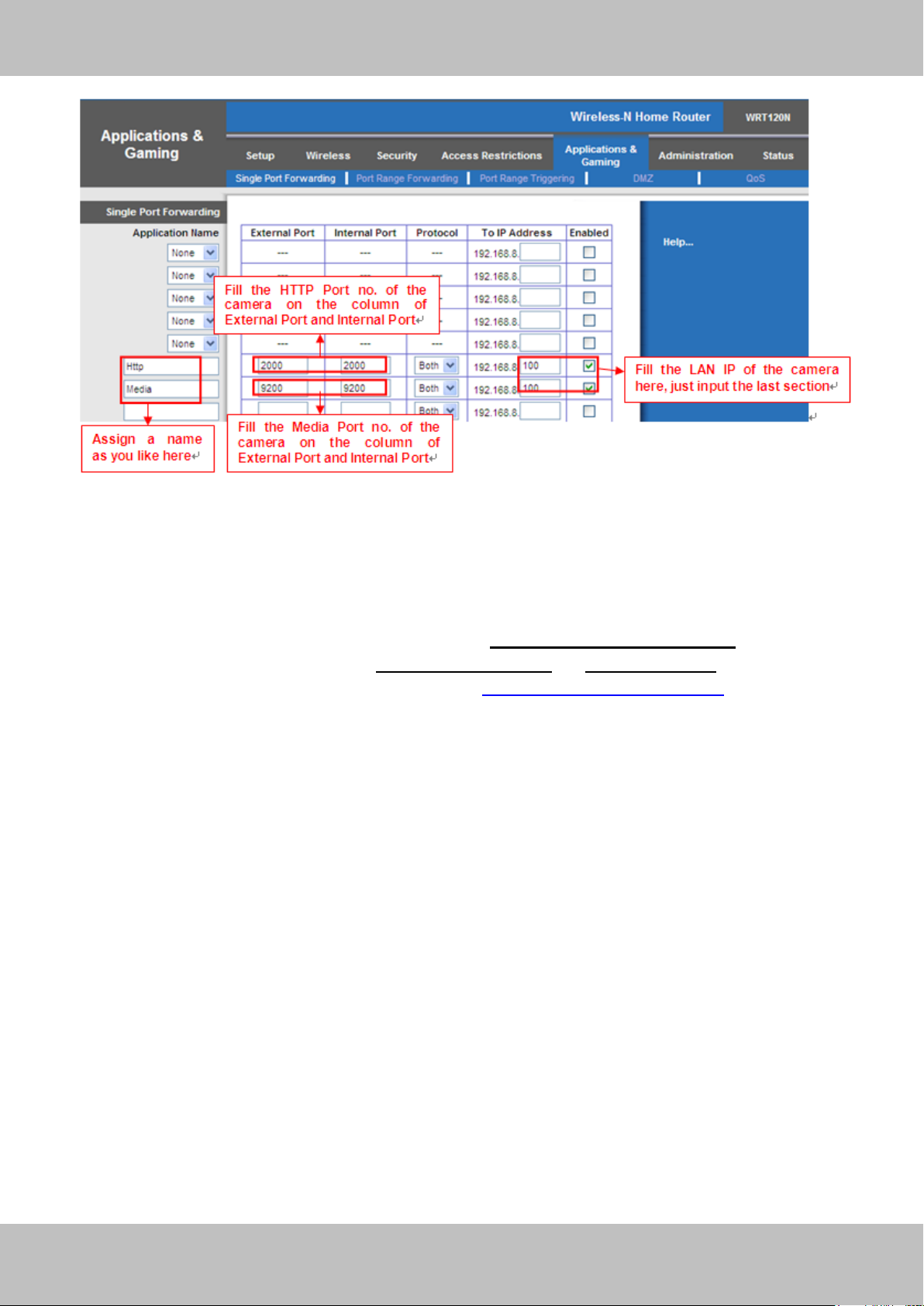
② Do port forwarding within the router
Example: The camera’s LAN IP address is http://192.168.8.100:2000 , Media
port no. is 9200.
Firstly, login the router, goes to the menu of Port Forwarding or Port Trigger (or named Virtue
Server on some brands of router). Take Linksys brand router as an example, Login the
router, and goes to Applications & Gaming->Single Port Forwarding.
Secondly, Create a new column by LAN IP address & HTTP Port No. of the camera within the
router showed as below.
Page 34
33
wwwwww..ffoossccaamm..ccoomm
SShheennzzhheenn FFoossccaamm IInntteelllliiggeenntt TTeecchhnnoollooggyy CCoo..,, LLiimmiitteedd
TTeell:: 8866 775555 22667744 55666688 FFaaxx:: 8866 775555 22667744 55116688
33
Figure 3.30
③ Use domain name to access the camera via internet
After the port forwarding is finished, you can use the domain name+ http no. to access the
camera via internet. Take hostname ycxgwp.no-ip.info and http no. 2000for example, the
accessing link of the camera via internet would be http:// ycxgwp.no-ip.info:2000
Page 35
34
wwwwww..ffoossccaamm..ccoomm
SShheennzzhheenn FFoossccaamm IInntteelllliiggeenntt TTeecchhnnoollooggyy CCoo..,, LLiimmiitteedd
TTeell:: 8866 775555 22667744 55666688 FFaaxx:: 8866 775555 22667744 55116688
34
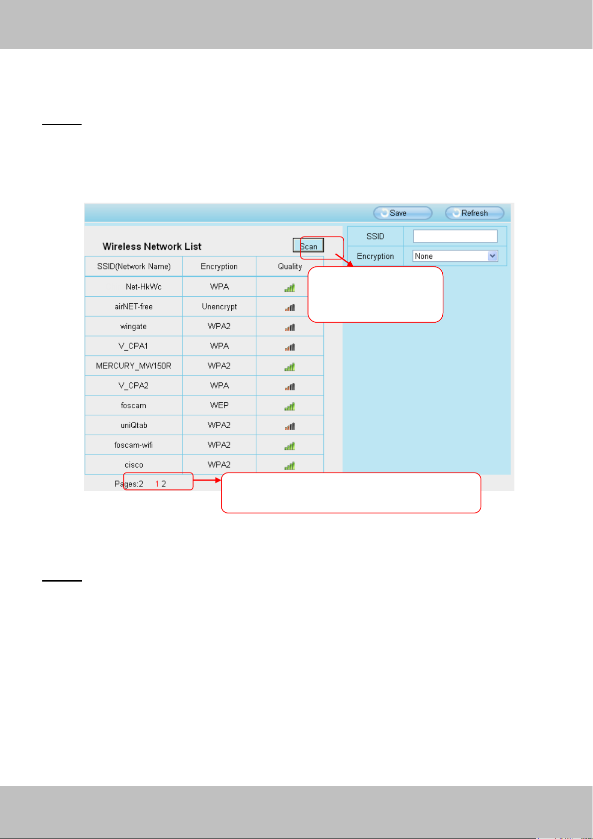
Click the Page number to see other wireless
networks devices if there are more than 10.
Click the Scan button
to search for wireless
networks.
3.3.4 WiFi
Step 1: Choose “Settings” on the top of the camera interface, and go to the “Network” panel on
the left side of the screen, then click “Wireless Settings.”
Click the Scan button and the camera will detect all wireless networks around the area. It should
also display your router in the list (Figure 3.31).
Figure 3.31
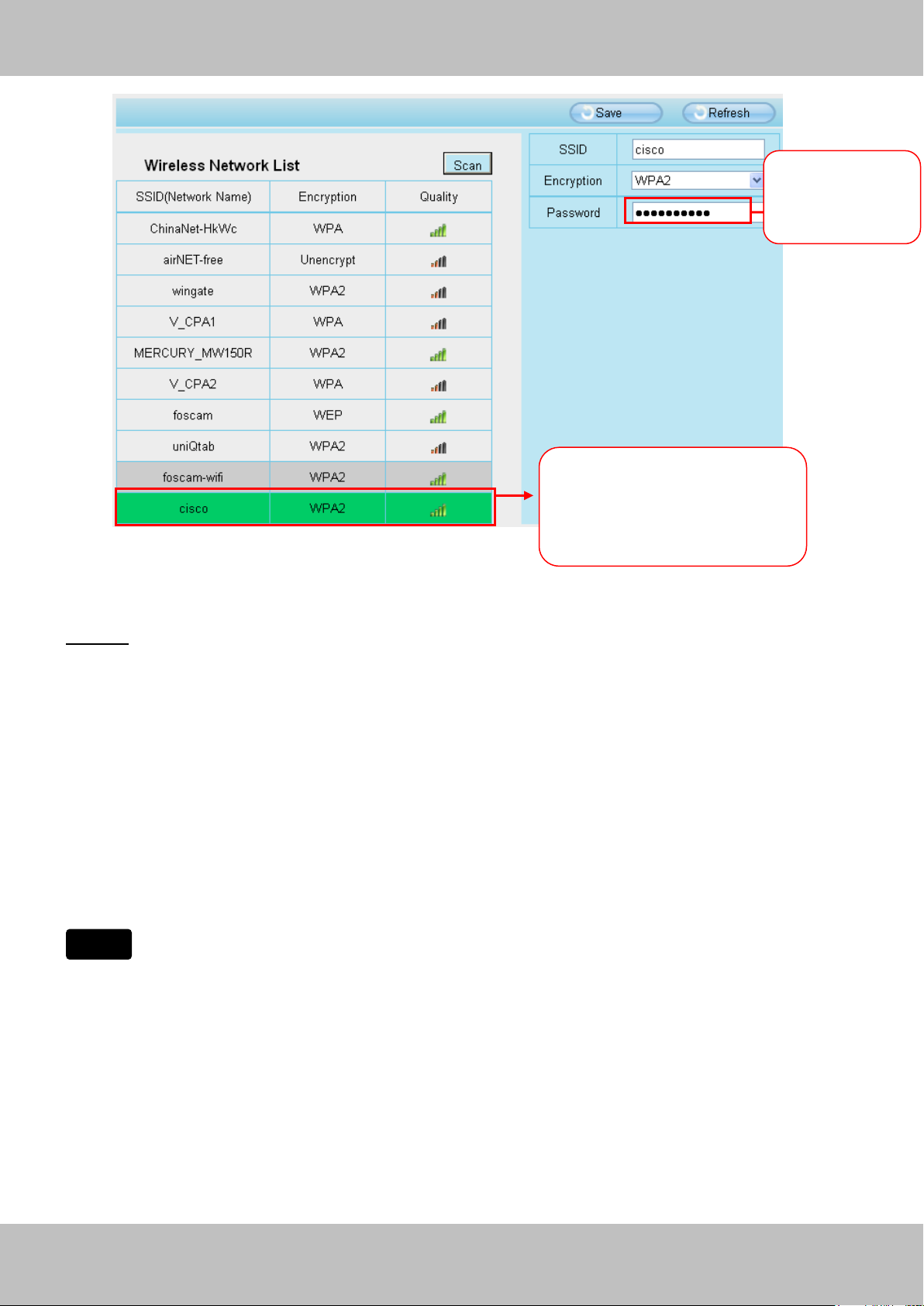
Step 2: Click the SSID (name of your router) in the list, the corresponding information related to
your network, such as the name and the encryption, will be filled into the relevant fields
automatically.
You will only need to fill in the password of your network. Make sure that the SSID, Encryption
and the password you filled in are exactly the same for your router.
Page 36
35
wwwwww..ffoossccaamm..ccoomm
SShheennzzhheenn FFoossccaamm IInntteelllliiggeenntt TTeecchhnnoollooggyy CCoo..,, LLiimmiitteedd
TTeell:: 8866 775555 22667744 55666688 FFaaxx:: 8866 775555 22667744 55116688
35
Note
1 Click the SSID of your router
and the relevant information
will be filled in the fields
automatically.
2 Enter the
password of
your router
Figure 3.32
Step 3: Please click on the Save button after all settings have been entered and disconnect the
network cable. Never shut down the power of the camera until the IP camera is able to connect
to the wireless network.
The LAN IP address will disappear on the window of IP Camera Tool when the camera is
configuring a wireless connection. Wait about 1 minute, the camera should obtain a wireless
connection, and the LAN IP of the camera will show again on the window of the IP Camera Tool.
The IP address may have changed after the camera receives a wireless connection; we
recommend setting a static local IP address if this IP address changes by right clicking the
camera in IP Camera Tools, setting a static IP, and pushing OK (see Figure3.35/3.36).
Congratulations! You have set up the wireless connection of the camera successfully.
If you fail to make a wireless connection, please refer to your seller or
contact us directly for assistance.
Page 37
36
wwwwww..ffoossccaamm..ccoomm
SShheennzzhheenn FFoossccaamm IInntteelllliiggeenntt TTeecchhnnoollooggyy CCoo..,, LLiimmiitteedd
TTeell:: 8866 775555 22667744 55666688 FFaaxx:: 8866 775555 22667744 55116688
36
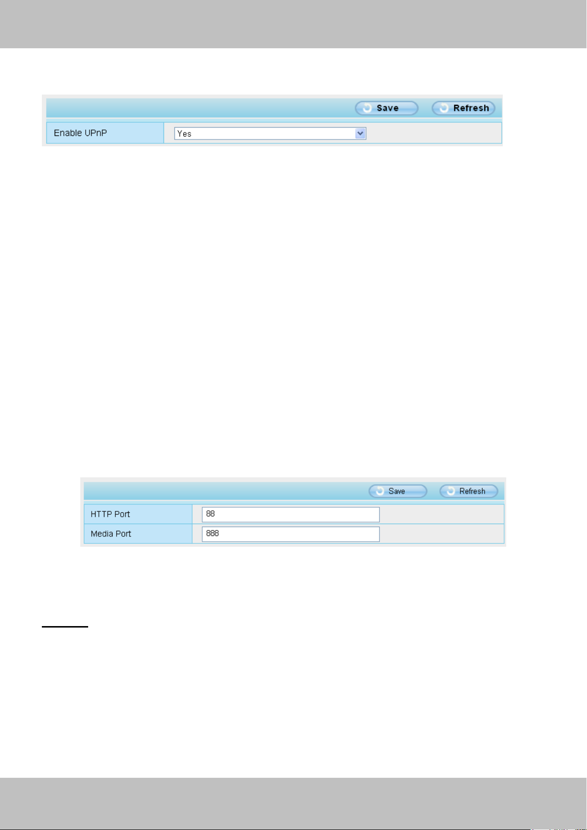
3.3.5 UPnP
Figure 3.33
The camera’s software will be configured for port forwarding. There may be issues with your
routers security settings, and sometimes may error. We recommend you configure port
forwarding manually on your router (Figure 3.30).
3.3.6 Port
This camera supports HTTP Port and Media Port. The Media port is used to view the camera’s
video stream, HTTP Port is used to access the camera remotely. If you want to access the
camera and view the video, the Media Port and the HTTP Port must both be configured correctly.
HTTP port / Media port: By default, the HTTP port is set to 88 and the Media port is set to 888.
Also, they can be assigned with another port number between 1 and 65535. But make sure they
canl not be conflict with other existing ports like 25, 21.
Figure 3.34
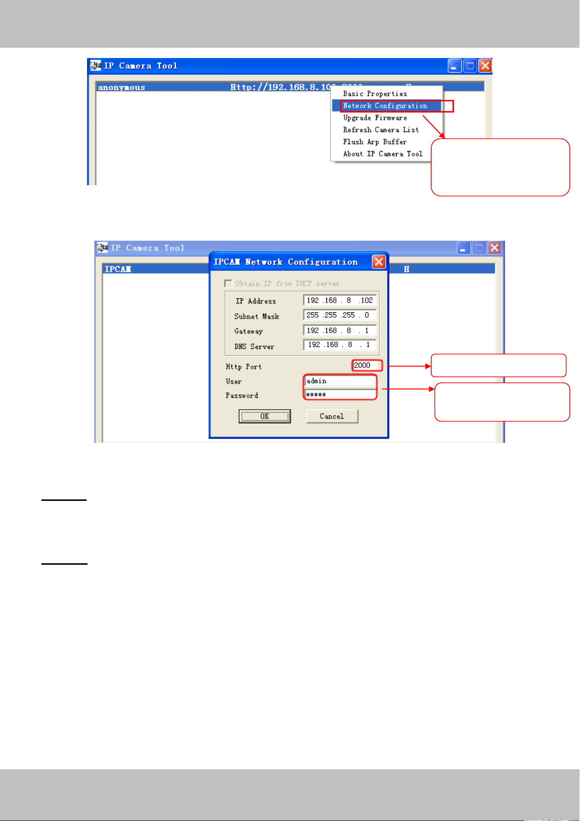
Another way to change the HTTP port no.
Step 1: Open the IP Camera Tool, select the camera you would like to change the port of, right
click on the IP address, and click on ”Network Configuration”, this brings up the network
configuration box as shown in Figure 3.35 and 3.36.
Page 38
37
wwwwww..ffoossccaamm..ccoomm
SShheennzzhheenn FFoossccaamm IInntteelllliiggeenntt TTeecchhnnoollooggyy CCoo..,, LLiimmiitteedd
TTeell:: 8866 775555 22667744 55666688 FFaaxx:: 8866 775555 22667744 55116688
37
Select which camera
you’d like to change the
port for, and right click
Modify the Http Port.
Enter the Username and
password, click OK.
Figure 3.35
Figure 3.36
Step 2: Enter the username and password of the Administrator (default username is admin with
a blank password), and click “OK” to apply changes.
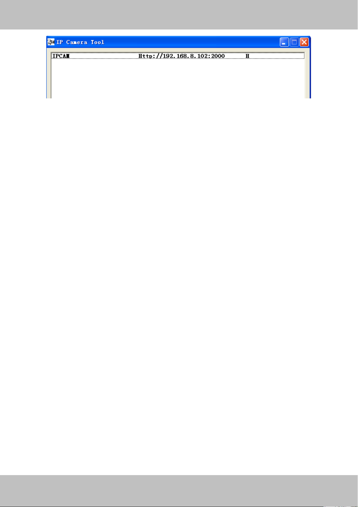
Step 3: Wait around 10 seconds, you’ll see that the camera’s LAN IP address has changed. In
our example it was changed to 2000, so we see http://192.168.8.102:2000 in IP Camera Tool.
Also, the LAN IP address is now fixed at a static IP address of http://192.168.8.102:2000. This IP
address will not change even if the camera is powered off and back on, the camera will remain
on this LAN IP address. This is very important that a static LAN IP address is set, or you may
have problems later with remote access and seeing the camera remotely if the camera loses
power and reconnects on a different LAN IP address. Make sure you set a static LAN IP address!
Page 39
38
wwwwww..ffoossccaamm..ccoomm
SShheennzzhheenn FFoossccaamm IInntteelllliiggeenntt TTeecchhnnoollooggyy CCoo..,, LLiimmiitteedd
TTeell:: 8866 775555 22667744 55666688 FFaaxx:: 8866 775555 22667744 55116688
38
Note: 1 Http port and Media port must be different.
2 If the camera cannot be accessed, please make sure the port forwarding is succeed.
Page 40
39
wwwwww..ffoossccaamm..ccoomm
SShheennzzhheenn FFoossccaamm IInntteelllliiggeenntt TTeecchhnnoollooggyy CCoo..,, LLiimmiitteedd
TTeell:: 8866 775555 22667744 55666688 FFaaxx:: 8866 775555 22667744 55116688
39
3.4 Video
This section allows you to configure Video stream settings, On screen display and Snapshot
settings.
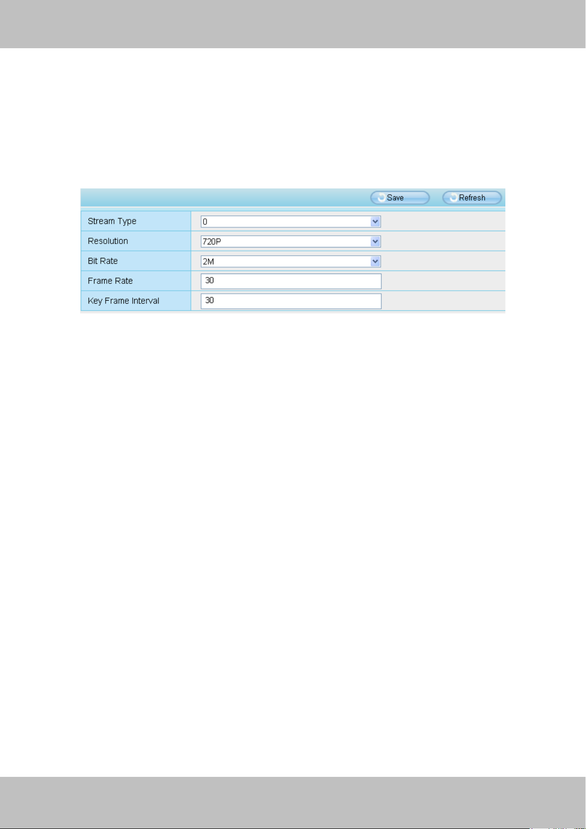
3.4.1 Settings
Figure 3.37
Stream type: There are four types to identify different streams you have set.
Resolution: The camera supports two types: 720P, VGA. The higher the resolution is, the
clearer video will become. But the code flux will become larger too, and it will take up more
bandwidth.
Bit rate: Generally speaking, the larger the bit rate is, the clearer video will become. But the bit
rate configuration should combine well with the network bandwidth. When the bandwidth is very
narrow, and bit rate is large, that will lead to video can not play well.
Frame rate: Note that a larger frame size takes up more bandwidth. When the video format is
50Hz, the maximum frame rate is 25 fps. When the video format is 60Hz, the maximum frame
rate is 30 fps. You should lower frame rate when the bandwidth is limited. Normally, when the
frame rate above 15, you can achieve fluently video.
Key Frame Interval: The time between last key frame and next key frame. The shorter the
duration, the more likely you will get a better video quality, but at the cost of higher network
bandwidth consumption.
Page 41
40
wwwwww..ffoossccaamm..ccoomm
SShheennzzhheenn FFoossccaamm IInntteelllliiggeenntt TTeecchhnnoollooggyy CCoo..,, LLiimmiitteedd
TTeell:: 8866 775555 22667744 55666688 FFaaxx:: 8866 775555 22667744 55116688
40
3.4.2 On Screen Display
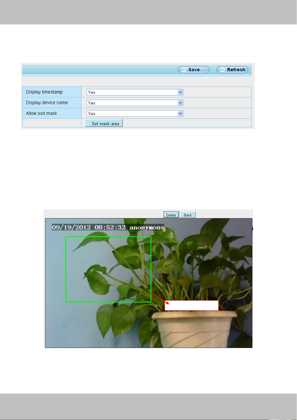
This page is used to add timestamp and device name on the video.
Figure 3.38
Display timestamp: There are two options: Yes or NO. Select Yes and you can see the system
date on the video,
Display device name: There are two options: Yes or NO. Select Yes and you can see the
device name on the video,
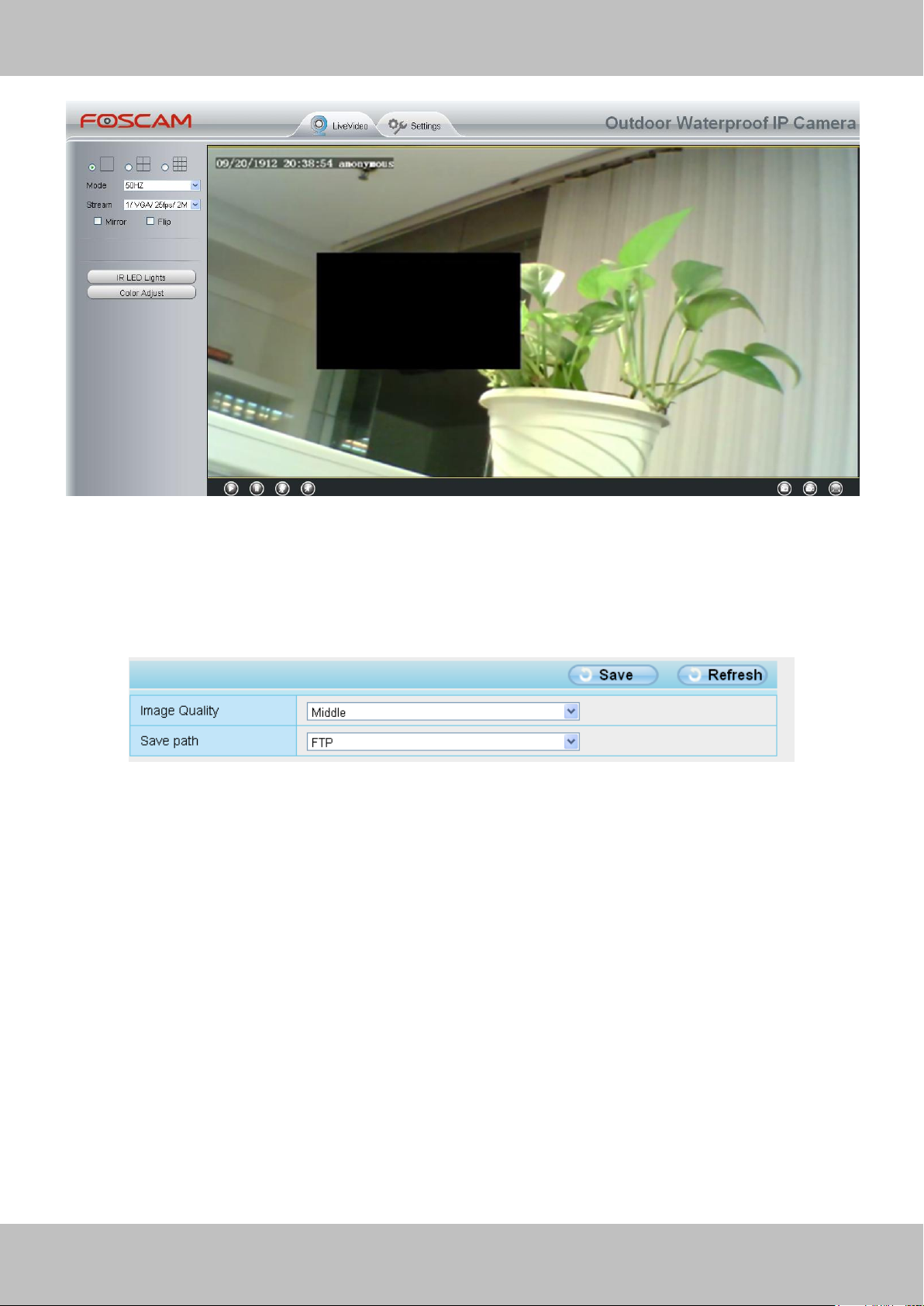
Allow osd mask: There are two options: Yes or NO. Select yes and draw a mask area on the
video, the mask area will be black on the video.
Figure 3.39
Click Back button and return to the OSD page, click Save to take effect.
Back to the surveillance window, you can see the mask area as the following picture:
Page 42
41
wwwwww..ffoossccaamm..ccoomm
SShheennzzhheenn FFoossccaamm IInntteelllliiggeenntt TTeecchhnnoollooggyy CCoo..,, LLiimmiitteedd
TTeell:: 8866 775555 22667744 55666688 FFaaxx:: 8866 775555 22667744 55116688
41
Figure 3.40
3.4.3 Snapshot Settings
On this page you can set the snapshot pictures’ image quality and the storage path.
Figure 3.41
Image Quality: Low, Middle and High. The higher the quality, the picture will be clearer.
Save Path: FTP. If you have done FTP and Alarm settings, when alarming, the camera will snap
pictures to the FTP automatically.
Page 43
42
wwwwww..ffoossccaamm..ccoomm
SShheennzzhheenn FFoossccaamm IInntteelllliiggeenntt TTeecchhnnoollooggyy CCoo..,, LLiimmiitteedd
TTeell:: 8866 775555 22667744 55666688 FFaaxx:: 8866 775555 22667744 55116688
42
1
2
3
4
6 5 7
3.5 Alarm
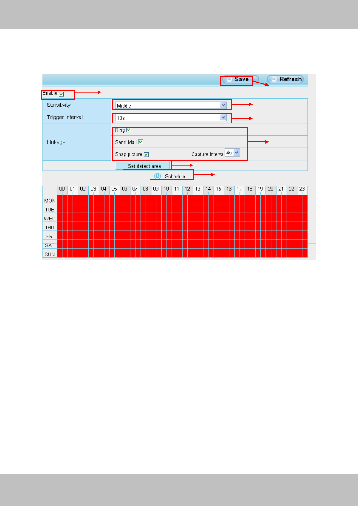
IP Camera supports Motion Detection Alarm, when the motion has been detected, it will send
emails or upload images to FTP.
Figure 3.42
To enable motion detection, follow the steps below:
1 Enable Motion detection
2 Sensitivity---- It supports three modes: Low, Middle and High. The higher the sensitivity, the
camera will be more easily alarmed. Select one motion sensitivity.
3 Trigger interval--- The interval time between two motion detections. Here supports
5s/6s/7s/8s/9s/10s/11s/12s/13s/14s/15s. Select one interval time.
4 Select the alarm indicators
When the motion has been detected, the alarm status will turn to Detect alarm.
Page 44
43
wwwwww..ffoossccaamm..ccoomm
SShheennzzhheenn FFoossccaamm IInntteelllliiggeenntt TTeecchhnnoollooggyy CCoo..,, LLiimmiitteedd
TTeell:: 8866 775555 22667744 55666688 FFaaxx:: 8866 775555 22667744 55116688
43
There are three alarm indicators:
A Ring
If the camera has connected with a speaker or other audio output device, if you select Ring,
when the motion has been detected, the people around the camera will hear beep alarm sound.
B Send Mail
If you want to receive alarm emails when motion is detected, you must select Send Mail and set
Mail Settings first. The alarm email cannot contain the alarm picture if you have not selected
Snap picture.
C Snap picture
If you select this checkbox, when the motion has been detected, the camera will snap the live
view window as a still picture and load it to the FTP. If you select Send Email, at the same time
the picture will be send to you as an attachment. Make sure you have set FTP and set FTP as
the storage path in Video->Snapshot Settings panel.
Capture interval: The interval time between two pictures.
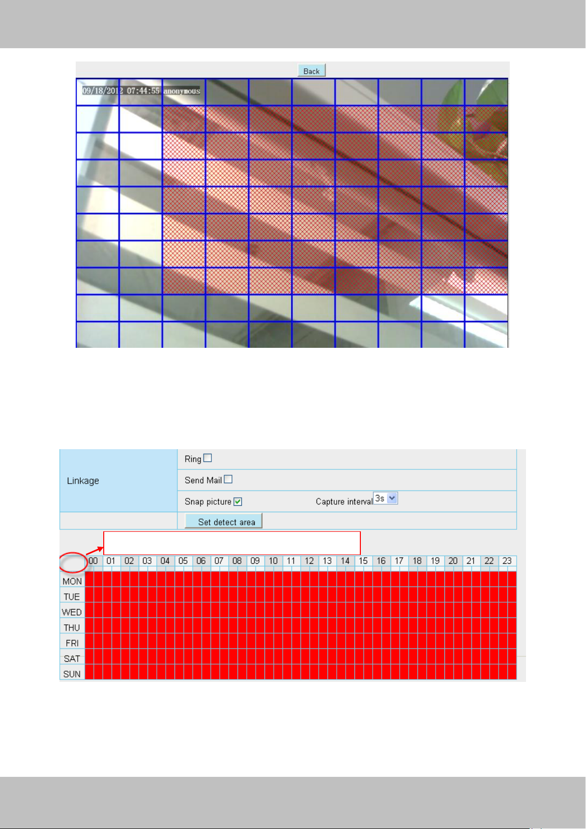
5 Set detect area
Click set detect area and it pop up a window, then you can draw the detection area. Click Back
button after settings. When something moving in the detection area, the camera will alarm.
Page 45
44
wwwwww..ffoossccaamm..ccoomm
SShheennzzhheenn FFoossccaamm IInntteelllliiggeenntt TTeecchhnnoollooggyy CCoo..,, LLiimmiitteedd
TTeell:: 8866 775555 22667744 55666688 FFaaxx:: 8866 775555 22667744 55116688
44
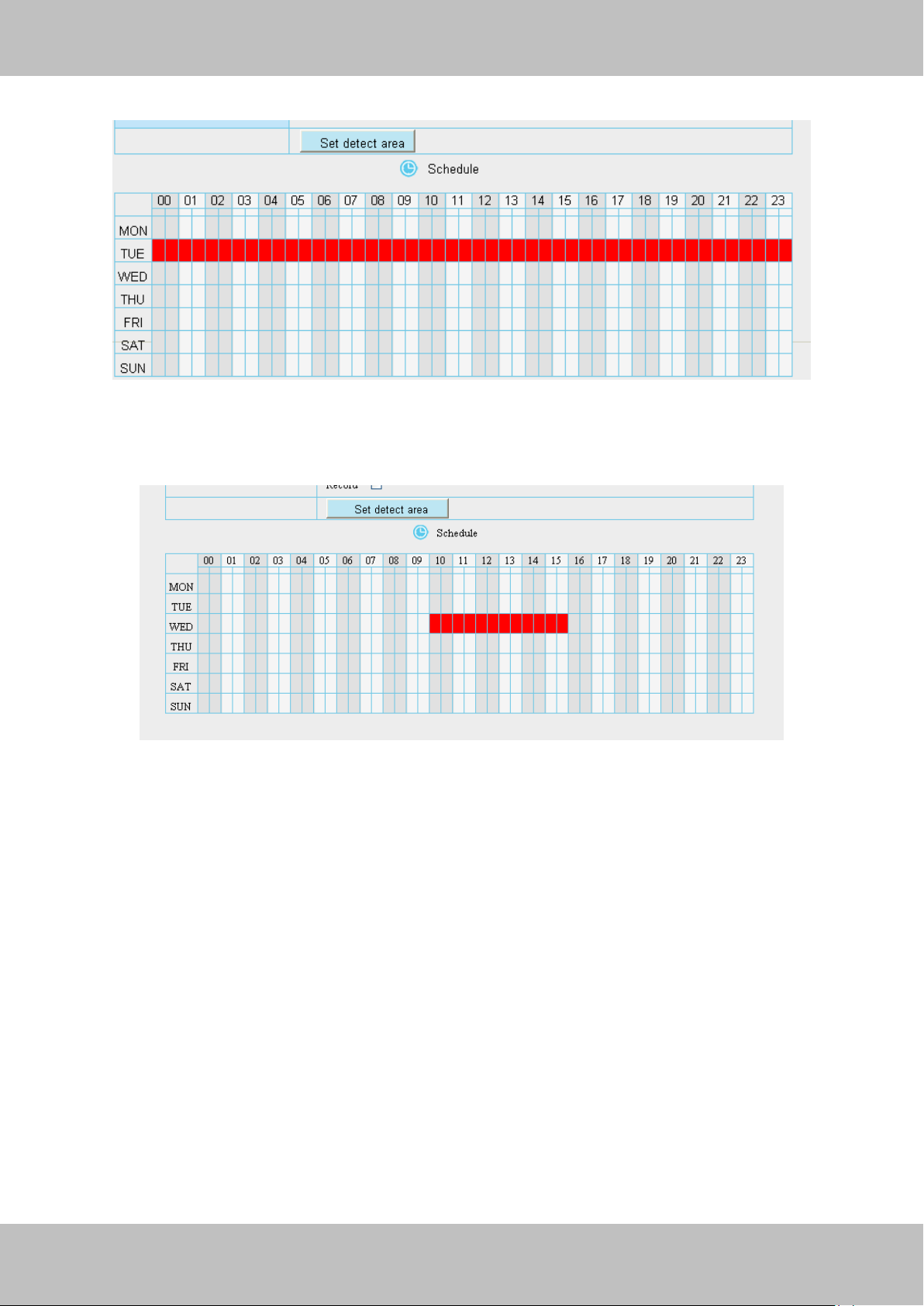
Click this button and select all time range
Figure 3.43
6 Alarm Schedule
① Alarm anytime when motion is detected
Click the black button up the MON, you will see all time range turn red. When something moving
in the detection area at anytime, the camera will alarm.
Figure 3.44
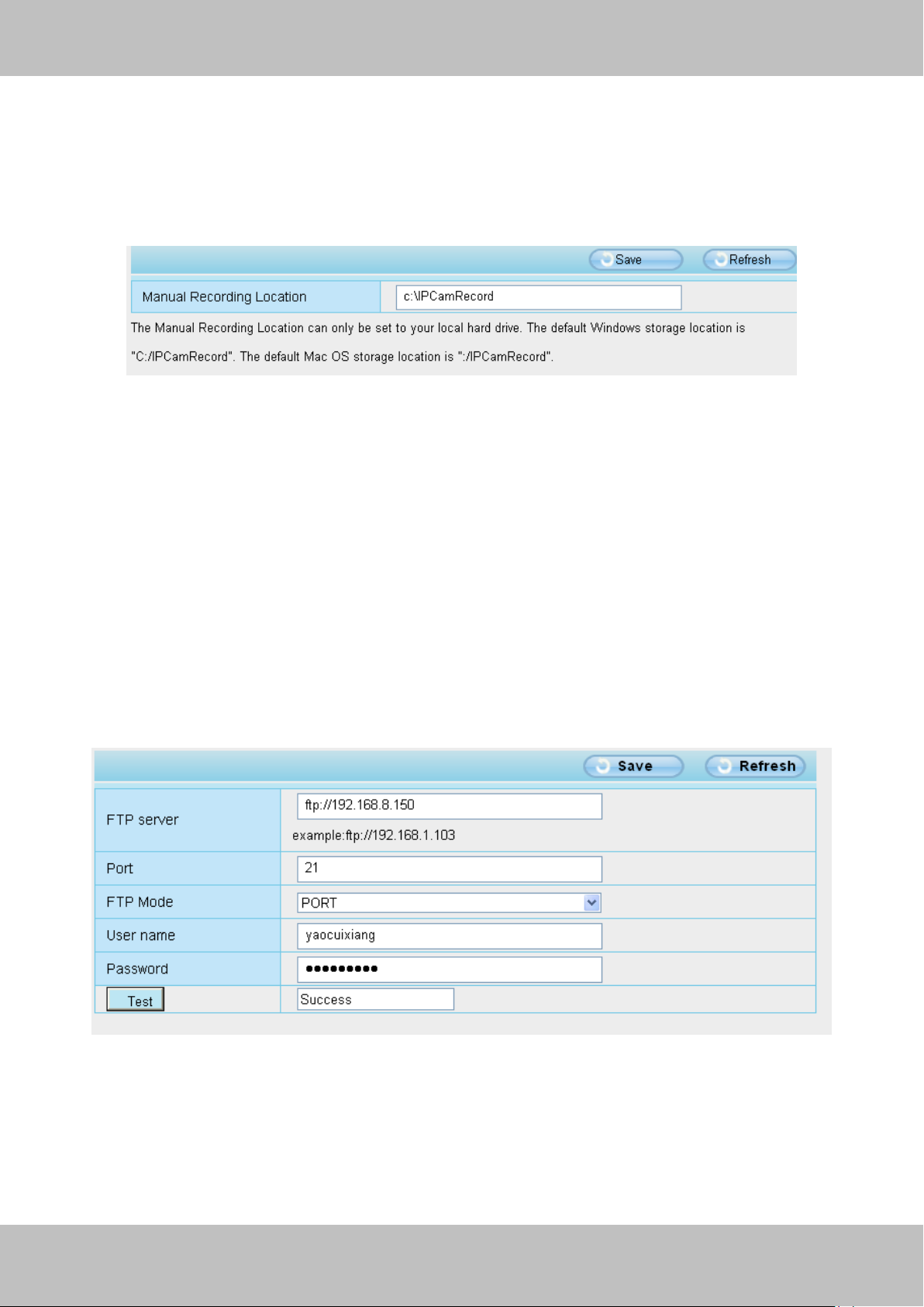
② Specify an alarm schedule
Click the week day words, the corresponding column will be selected. For example, click TUE,
the all column of TUE turns to red, that means during Tuesday whole day, when something
Page 46
45
wwwwww..ffoossccaamm..ccoomm
SShheennzzhheenn FFoossccaamm IInntteelllliiggeenntt TTeecchhnnoollooggyy CCoo..,, LLiimmiitteedd
TTeell:: 8866 775555 22667744 55666688 FFaaxx:: 8866 775555 22667744 55116688
45
moving in the detection area, the camera will alarm.
Figure 3.45
③ Press the left mouse and drag it on the time boxes, you can select the serial area,
Figure 3.46
7 Click Save button to take effect. When the motion is detected during the detection time in the
detection area, the camera will alarm and adopt the corresponding alarm indicators.
NOTE: You must set the detection area and detection schedule, or else there is no alarm
anywhere and anytime.
Page 47
46
wwwwww..ffoossccaamm..ccoomm
SShheennzzhheenn FFoossccaamm IInntteelllliiggeenntt TTeecchhnnoollooggyy CCoo..,, LLiimmiitteedd
TTeell:: 8866 775555 22667744 55666688 FFaaxx:: 8866 775555 22667744 55116688
46
3.6 Record
On this page you can change the manually recording storage path, the default storage path is
C:\IPCamRecord.
Figure 3.47
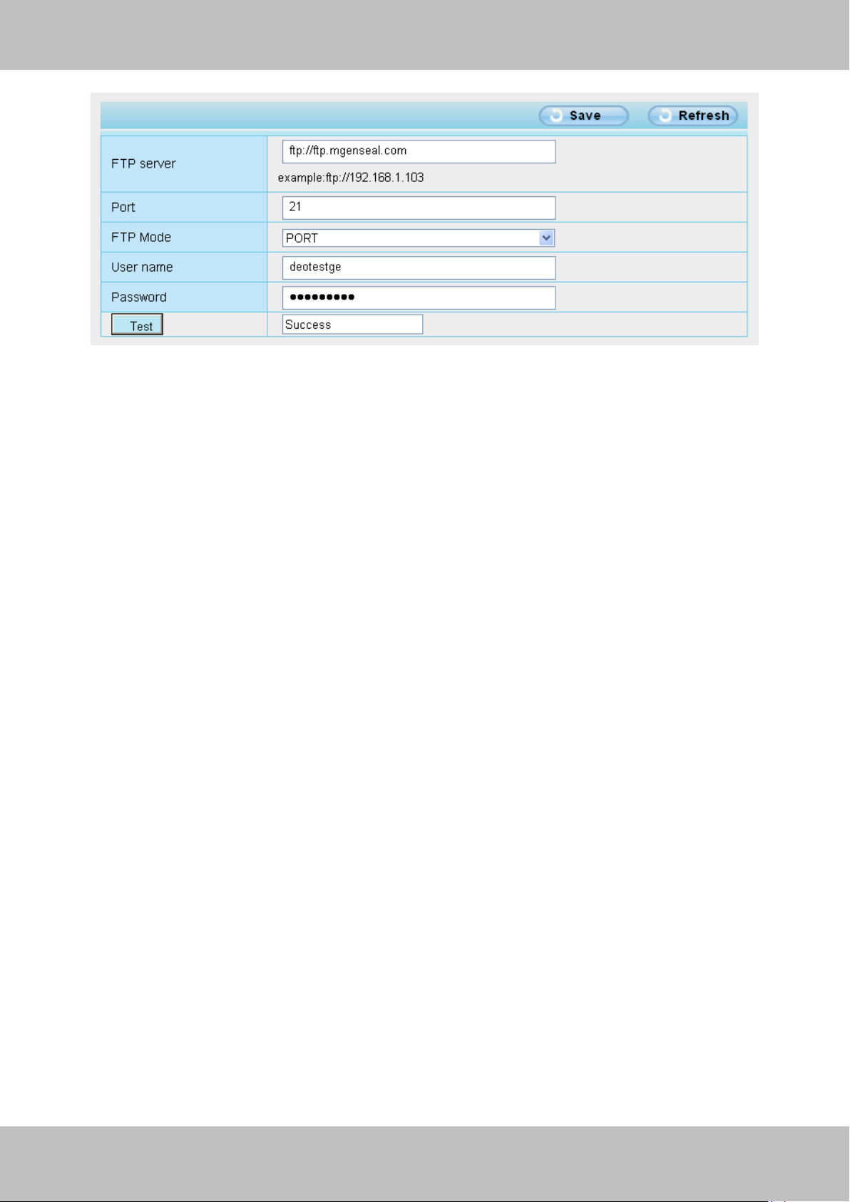
3.7 Path Settings
If you want to upload record images to your FTP server,you can set FTP Settings.
Figure 3.48
Page 48
47
wwwwww..ffoossccaamm..ccoomm
SShheennzzhheenn FFoossccaamm IInntteelllliiggeenntt TTeecchhnnoollooggyy CCoo..,, LLiimmiitteedd
TTeell:: 8866 775555 22667744 55666688 FFaaxx:: 8866 775555 22667744 55116688
47
Figure 3.49
FTP server: If your FTP server is located on the LAN, you can set as Figure 3.48.
If you have an FTP server which you can access on the internet, you can set as Figure 3.49.
Port: Default is port 21. If changed, external FTP client program must change the server
connection port accordingly.
FTP Mode: Here supports two modes: PORT and PASV.
Username/password: The FTP account and password.
Click Save to take effect.
Click Test to see if FTP has been successfully configured.
Page 49
48
wwwwww..ffoossccaamm..ccoomm
SShheennzzhheenn FFoossccaamm IInntteelllliiggeenntt TTeecchhnnoollooggyy CCoo..,, LLiimmiitteedd
TTeell:: 8866 775555 22667744 55666688 FFaaxx:: 8866 775555 22667744 55116688
48
3.8 Firewall
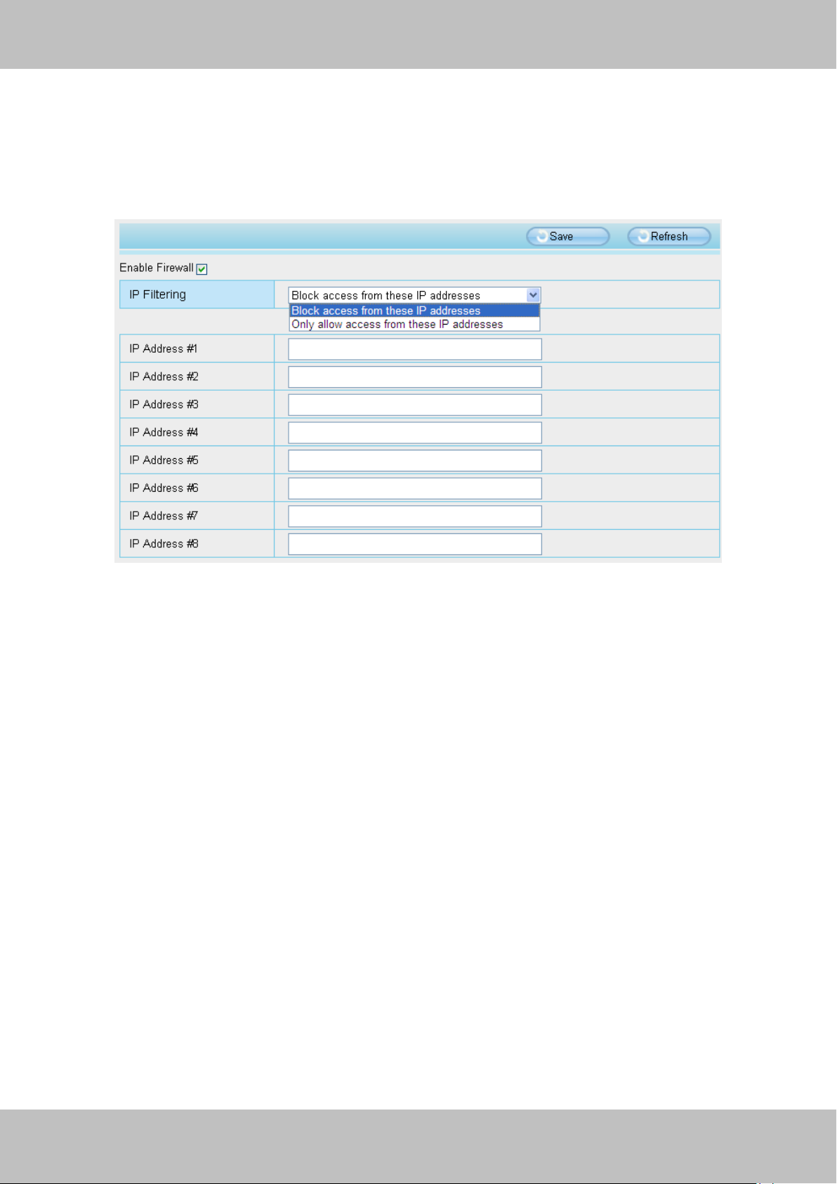
This section explains how to control the access permission by checking the client PC’s IP
addresses. It is composed of the following columns: Block access from these IP addresses
and Only allow access from these IP addresses.
Figure 3.50
Enable firewall, If you select Only allow access from these IP addresses and fill in 8 IP addresses
at most, only those clients whose IP addresses listed in the Only allow access from these IP
addresses can access the Network Camera. If you select Block access from these IP
addresses, only those clients whose IP addresses are in the IP list cannot access the Network
Camera.
Click Save to take effect.
Page 50
49
wwwwww..ffoossccaamm..ccoomm
SShheennzzhheenn FFoossccaamm IInntteelllliiggeenntt TTeecchhnnoollooggyy CCoo..,, LLiimmiitteedd
TTeell:: 8866 775555 22667744 55666688 FFaaxx:: 8866 775555 22667744 55116688
49
3.9 System
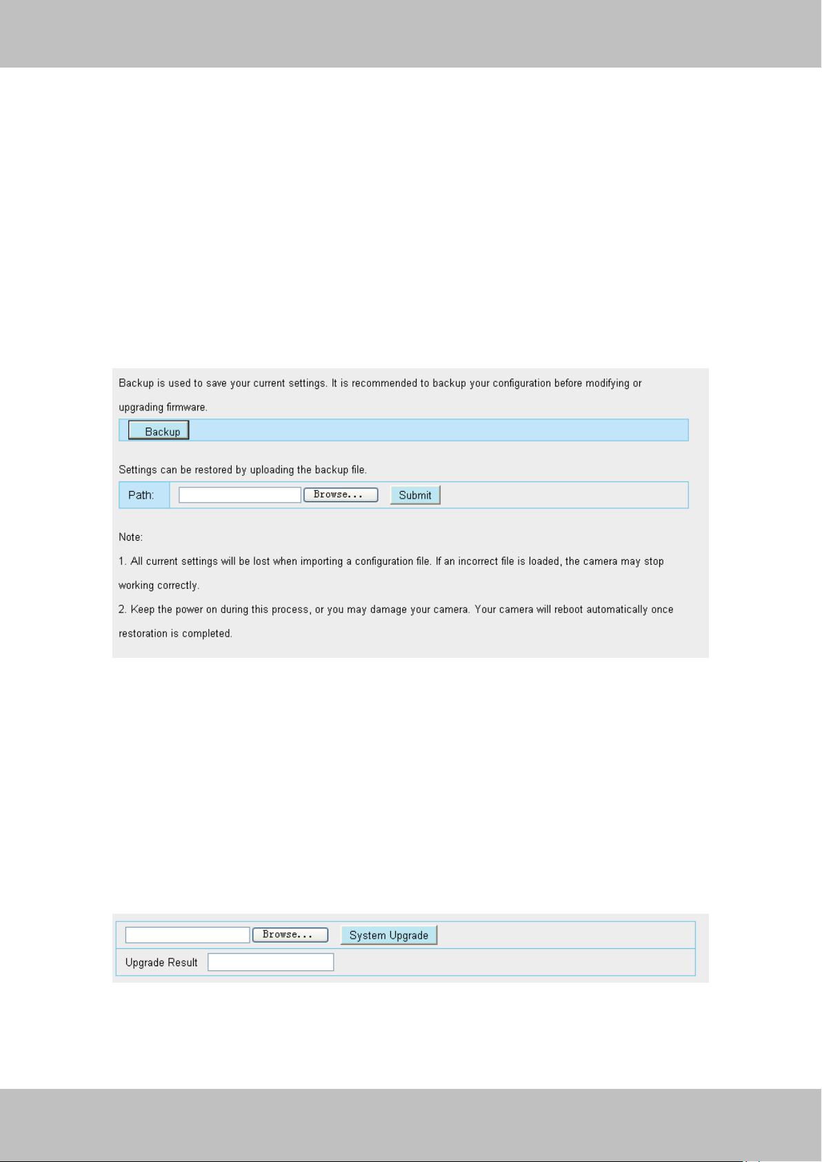
In this panel, you can back up/restore your camera settings, upgrade the firmware to the latest
version, restore the camera to default settings and reboot the device.
3.9.1 Back up& Restore settings
Click Backup to save all the parameters you have set. These parameters will be stored in a bin
file for future use.
Click Browse and select the parameters file you have stored, then click Submit to restore the
restore the parameters.
Figure 3.51
3.9.2 System upgrade
Click Browse, choose the correct bin file( System firmware or Web UI) and then click System
upgrade.
Don’t shut down the power during upgrade. After upgrading, you can see the upgrade result.
Figure 3.52
If you want to verify the firmware version of you camera, please go to Device Status- Device
Information Page to check
Page 51
50
wwwwww..ffoossccaamm..ccoomm
SShheennzzhheenn FFoossccaamm IInntteelllliiggeenntt TTeecchhnnoollooggyy CCoo..,, LLiimmiitteedd
TTeell:: 8866 775555 22667744 55666688 FFaaxx:: 8866 775555 22667744 55116688
50
Enter the User name and
password
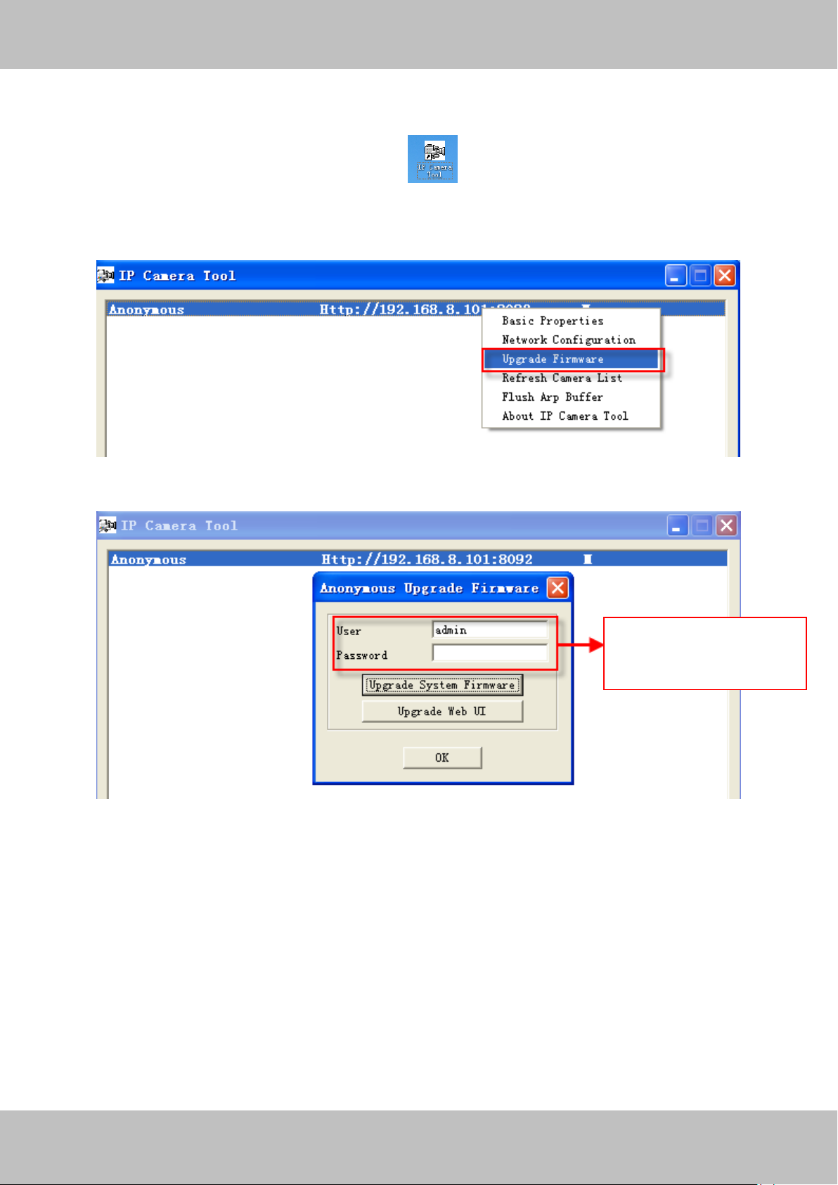
Upgrade Firmware by IP Camera Tool
Double click the IP Camera Tool shot icon , select the Camera IP that you want to
upgrade the firmware. Then select Upgrade Firmware and enter the username and password,
choose the firmware file, and upgrade.
Figure 3.53
Figure 3.54
CAUTION: If your camera works well with the current firmware, we recommend not upgrading.
Please don’t upgrade the firmware unnecessarily. Your camera may be damaged if
misconfigured during an upgrade.
NOTE:
1) Don’t upgrade the firmware through the web UI in WAN, or else the upgrade may be falied.
2) Please ensure you have download the correct firmware package for your camera before
Page 52
51
wwwwww..ffoossccaamm..ccoomm
SShheennzzhheenn FFoossccaamm IInntteelllliiggeenntt TTeecchhnnoollooggyy CCoo..,, LLiimmiitteedd
TTeell:: 8866 775555 22667744 55666688 FFaaxx:: 8866 775555 22667744 55116688
51
upgrading. Read the upgrade documentation (readme.txt file) in the upgrade package before
you upgrade.
3) Upon downloading the firmware check the sizes of the .bin files. They must match the size in
the readme.txt file. If not, please download the firmware again until the sizes are the same.
Your camera will not function correctly if a corrupt .bin file is used.
4) Normally, only Device WEB UI need to be upgrade, please do not try to upgrade the Device
Firmware.
5) Never shut down the power of the camera during upgrade until the IP camera restart and get
connected.
3.9.3 Factory Reset
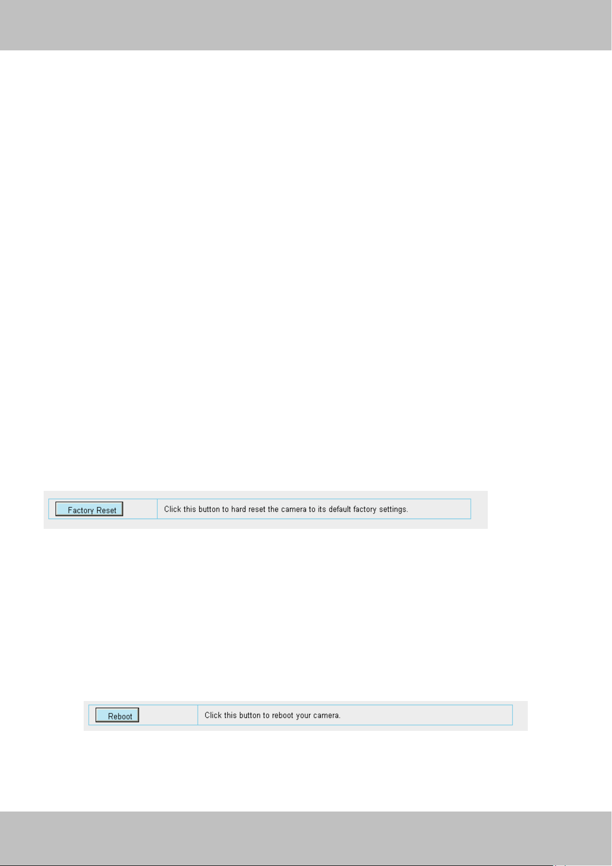
Click Factory Reset button and all parameters will return to factory settings if selected.
Figure 3.55
3.9.4 Reboot System
Click Reboot System to reboot the camera. This is similar to unplugging the power to the
camera.
Figure 3.56
Page 53
52
wwwwww..ffoossccaamm..ccoomm
SShheennzzhheenn FFoossccaamm IInntteelllliiggeenntt TTeecchhnnoollooggyy CCoo..,, LLiimmiitteedd
TTeell:: 8866 775555 22667744 55666688 FFaaxx:: 8866 775555 22667744 55116688
52
44 AAPPPPEENNDDIIXX
Click here to download
4.1 Frequently Asked Questions
NOTE: Any questions you would meet, please check Network connections firstly. Check the
working status revealed by the indicators on the network server, hub, exchange and network
card. If abnormal, check the network connections.
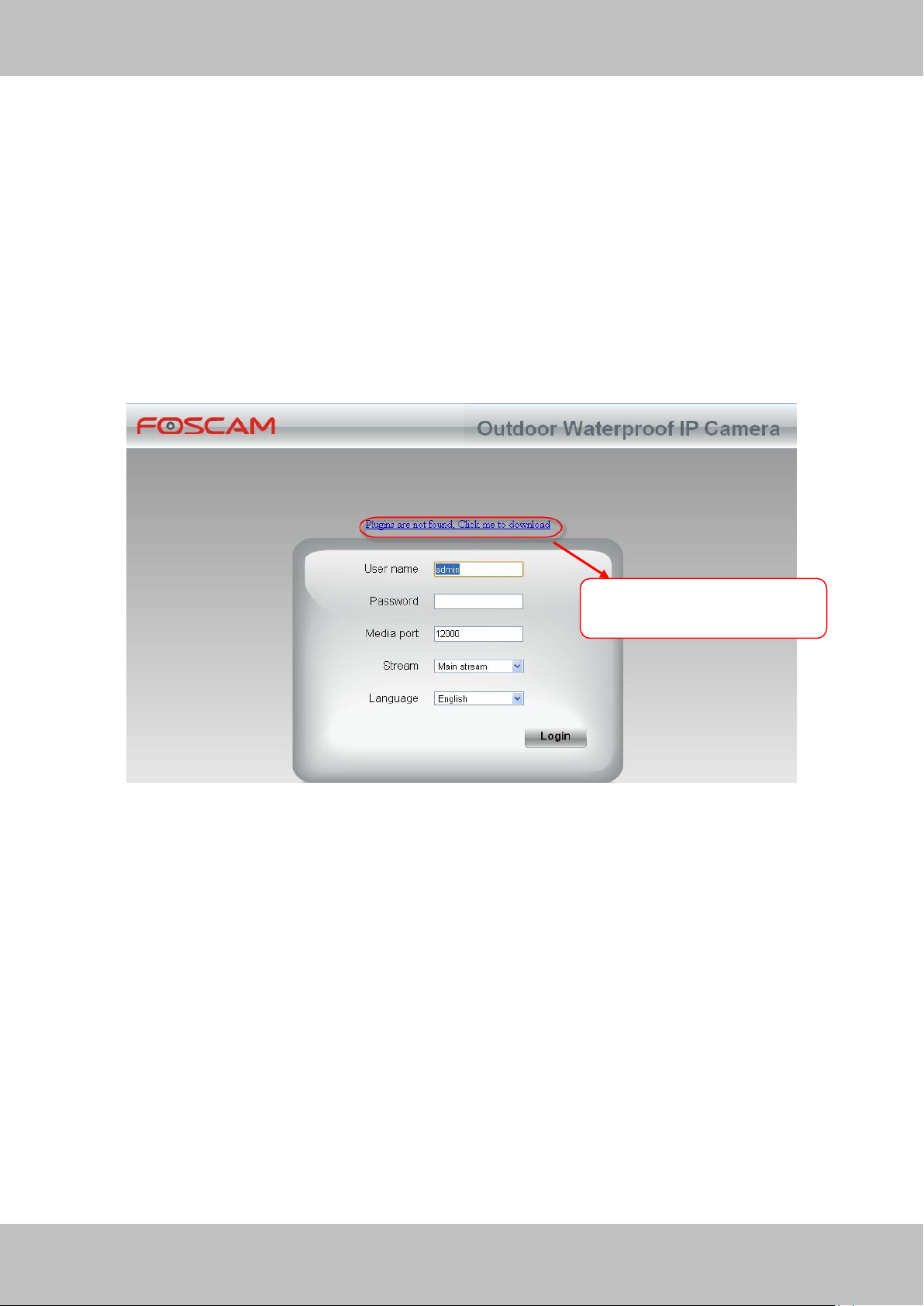
4.1.1 How to download and installl the ActiveX for Firefox users
For the first time login the camera, it may prompt you to download plugin.
Figure 4.1
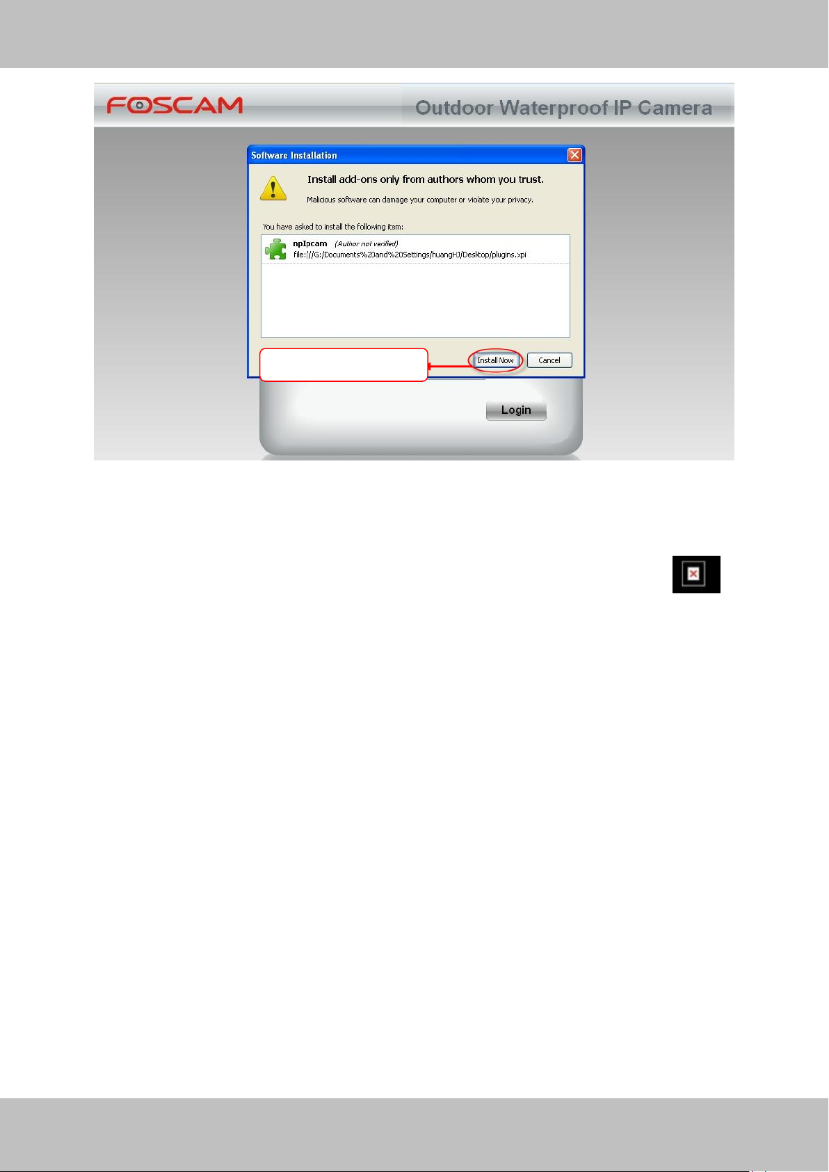
Drag the download file to Firefox web page and it will prompt you to Install it.
Page 54
53
wwwwww..ffoossccaamm..ccoomm
SShheennzzhheenn FFoossccaamm IInntteelllliiggeenntt TTeecchhnnoollooggyy CCoo..,, LLiimmiitteedd
TTeell:: 8866 775555 22667744 55666688 FFaaxx:: 8866 775555 22667744 55116688
53
Click Install Now
Figure 4.2
Reboot the Firefox after the plugin installation is successfully completely, then relogin the camera
again, you can see the surveillance window
NOTE: If you could not view living video after running the ActiveX, only a red cross in the
center of the video or just a black screen. Please change another port number to try.
Make sure all firewall or antivirus software on your computer does not block the active download
and installation. If you are unable to run the ActiveX control, try shutting down the firewall or
antivirus program.
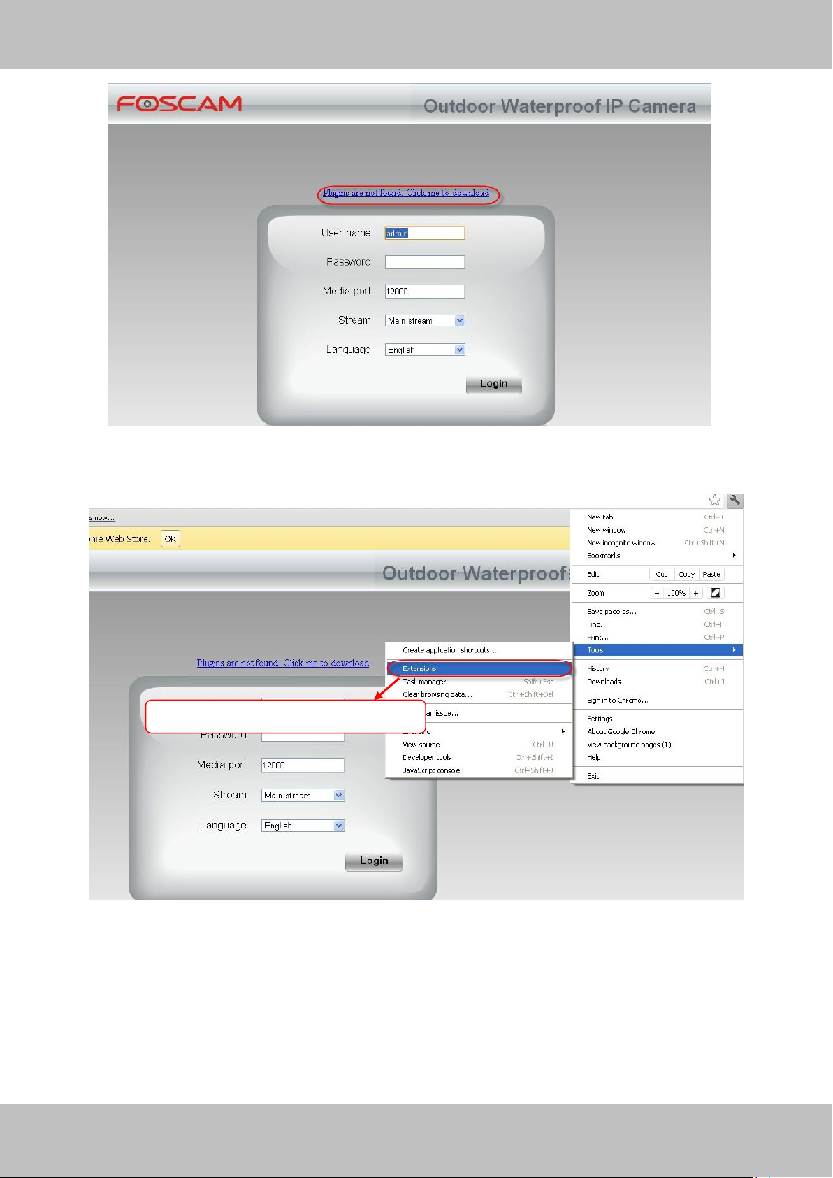
4.1.2 How to download and installl the ActiveX for Google Chrome users
For the first time login the camera, it will prompt you to download the ActiveX..
Page 55
54
wwwwww..ffoossccaamm..ccoomm
SShheennzzhheenn FFoossccaamm IInntteelllliiggeenntt TTeecchhnnoollooggyy CCoo..,, LLiimmiitteedd
TTeell:: 8866 775555 22667744 55666688 FFaaxx:: 8866 775555 22667744 55116688
54
Click Add button to install the plugin
Figure 4.3
Download the plugin and drag it to the Extensions page of Google Chrome.
.
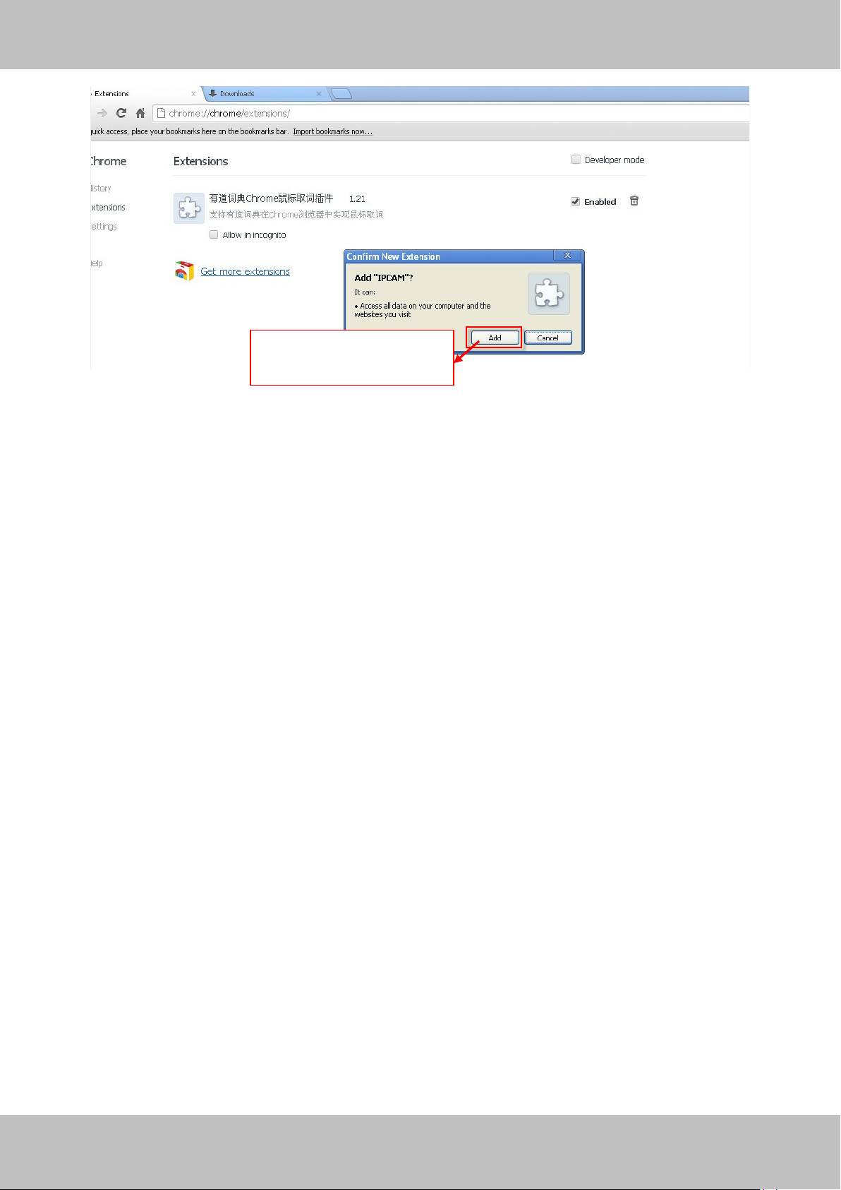
Figure 4.4
Click Add button to install the Plugins.
Page 56
55
wwwwww..ffoossccaamm..ccoomm
SShheennzzhheenn FFoossccaamm IInntteelllliiggeenntt TTeecchhnnoollooggyy CCoo..,, LLiimmiitteedd
TTeell:: 8866 775555 22667744 55666688 FFaaxx:: 8866 775555 22667744 55116688
55
Click Add button to install
the plugin
Figure 4.5
Reboot the browser and re-login the camera, you will see the surveillance window.
4.1.3 I have forgotten the administrator password
To reset the administrator password, you had better unplug the network cable firstly. After that,
press and hold down the RESET BUTTON about 5 seconds. Releasing the reset button, the
password will turn to the factory default.
Default administrator username/password: admin with blank password
4.1.4 Subnet doesn’t match
Check whether your ipcamera in the same subnet of your computer. The step is Control
PanelNetwork ConnectionsDbclick Local Area Connections Choose
GeneralProperties.(Figure 3.23/3.24) Check subnet mask, IP address and gateways. When
you set IP address please make sure they are in the same subnet. Otherwise you can't access
camera.
Page 57
56
wwwwww..ffoossccaamm..ccoomm
SShheennzzhheenn FFoossccaamm IInntteelllliiggeenntt TTeecchhnnoollooggyy CCoo..,, LLiimmiitteedd
TTeell:: 8866 775555 22667744 55666688 FFaaxx:: 8866 775555 22667744 55116688
56
4.1.5 Camera can not record when I click Record button or I can’t change the
manually record path
When you use Windows7 or Vista, you may be not able to do manually record or change the
record path because of the security settings of computer.
There are two ways to resolve this problem:
(1) Please add the camera as a trusted site to resolve this issue. The steps are
IE browserToolInternet PropertiesSecurityTrusted sitesSitesAdd
(2) Open IE browser, then right click, select “Run as administrator”
4.1.6 No Pictures Problems
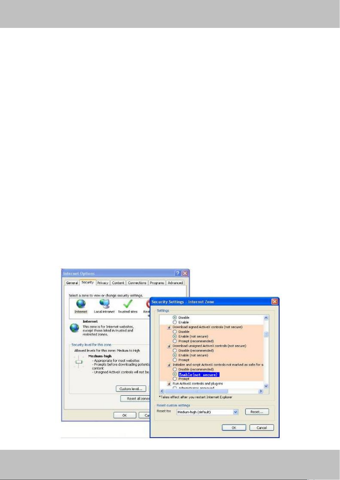
The video streaming is transmitted by the ActiveX controller. If ActiveX controller isn’t installed
correctly you will see no video image. You can resolve this problem by this way:
Download ActiveX controller and set the safety property of IE in the PC when you view it first
time: IE browserToolInternet ProperSecurityCustom LevelActiveX control and
Plug-ins. Three options of front should be set to be “Enable”, The ActiveX programs read by the
computer will be stored. As follows:
Enable: Download unsigned ActiveX controls
Enable: Initialize and script ActiveX controls not marked as safe
Enable: Run ActiveX controls and plug-ins
Page 58
57
wwwwww..ffoossccaamm..ccoomm
SShheennzzhheenn FFoossccaamm IInntteelllliiggeenntt TTeecchhnnoollooggyy CCoo..,, LLiimmiitteedd
TTeell:: 8866 775555 22667744 55666688 FFaaxx:: 8866 775555 22667744 55116688
57
Figure 4.6
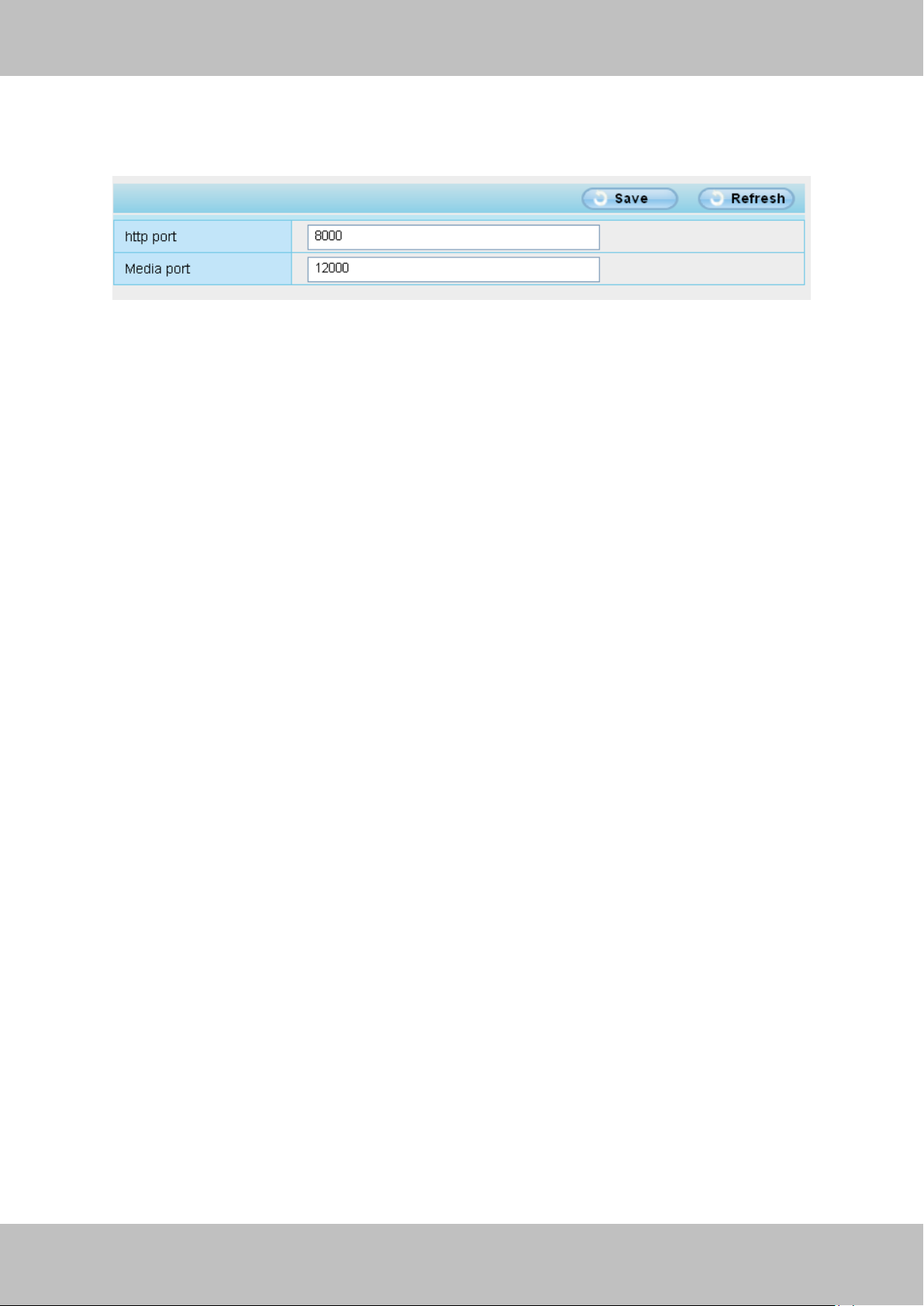
If you allow the ActiveX running, but still could not see living video. Please change another port
number to try. Don’t use port 8000.
Figure4.7
NOTE: Make sure that your firewall or anti-virus software does not block the camera or ActiveX.
If you could not see video, please shut down firewall or anti-virus software to try again.
4.1.7 Can’t access IP camera in internet
There are some reasons:
1 ActiveX controller is not installed correctly
2 The port which camera used is blocked by Firewall or Anti-virus software. Please change
another port number and try again. (Figure4.7)
3 Port forwarding is not successful(Figure3.30)
Check these settings and make sure they are correct.
4.1.8 UPnP always failed
UPnP only contains port forwarding in our recent software. Sometimes, it may be failed to do port
forwarding automatically because of firewall or anti-virus software. It also has much relation with
router’s security settings. So we recommend you do port forwarding manually. You can view
your camera in internet successfully after you do port forwarding manually in your router.
4.1.9 Camera can not connect wireless
If your camera could not connect wireless after you set wireless settings and plug out the cable.
Please check whether your settings are correct or not.
Normally, camera can’t connect wireless mainly because of wrong settings.
Make sure broadcast your SSID; use the same encryption for router and camera.
Page 59

58
wwwwww..ffoossccaamm..ccoomm
SShheennzzhheenn FFoossccaamm IInntteelllliiggeenntt TTeecchhnnoollooggyy CCoo..,, LLiimmiitteedd
TTeell:: 8866 775555 22667744 55666688 FFaaxx:: 8866 775555 22667744 55116688
58
Specification
FI9801W
Image Sensor
Image Sensor
High Definition Color CMOS Sensor
Lens
f : 4mm
Mini. Illumination
0.5Lux
Audio
Input/Output
Linear Input/Output, which can realize two-way
voice the intercom
Video
Image Compression
H.264
Image Frame Rate
25fps(50Hz), 30fps(60Hz),Down adjustable
Video
Resolution
720p(1280*720),VGA(640*480)
View
H.264 dual streaming
Image adjust
The brightness, contrast, saturation, chromaticity, is
adjustable
Infrared mode
Off & Manually
Night visibility
Φ5mm 36 IR LEDs, Night visibility up to 30 meters
Network
Ethernet
One 10/100Mbps RJ-45
Supported Protocol
TCP/IP、UDP/IP、HTTP、SMTP、FTP、DHCP、
DDNS、UPNP
Wireless Standard
WIFI(IEEE802.11b/g/n)
Support IP address
static IP address, dynamic IP address
Alarm
Alarm detection
The motion detecting
Alarm inform
Support Email、FTP etc alarm inform way
4.2 Default Parameters
Default network Parameters
IP address: obtain dynamically
Subnet mask: obtain dynamically
Gateway: obtain dynamically
DDNS: Embedded FOSCAM DDNS Service
Username and password
Default admin username: admin with a blank password
4.3 Specification
Page 60

59
wwwwww..ffoossccaamm..ccoomm
SShheennzzhheenn FFoossccaamm IInntteelllliiggeenntt TTeecchhnnoollooggyy CCoo..,, LLiimmiitteedd
TTeell:: 8866 775555 22667744 55666688 FFaaxx:: 8866 775555 22667744 55116688
59
Hardware
Interface
POWER Interface
DC 12V/2.0A (EU,US,AU adapter or other types
option, Power Consumption ﹤8 Watts
Audio Input/Output
Interface
One audio input jack, One audio output jack.
Reset Buttons
One Reset
Environment
Operate Temper
0° ~ 55°C (32°F ~ 131°F)
Operate Humidity
10% ~ 80% non-condensing
Storage Temper
-10°C ~ 60° (14°F ~ 140°F)
Storage Humidity
0% ~ 90% non-condensing
Dimension
177X87x76mm
Net Weight
910g
Gross Weight
1411g
PC
CPU
2.0GHZ or above (suggested 3.0GHz)
Requirements
Memory Size
256MB or above (suggested 1.0GHz)
Display Card
64M or above
Supported OS
Microsoft Windows 2000/XP/Vista ,Mac OS
Browser
IE6 and above version or compatible browser,
Firefox, Chrome, Safari or other standard browsers
Software
Upgrade
Upgrade from network
Certification
CE,FCC
5 OBTAINING TECHNICAL SUPPORT
While we hope your experience with the IPCAM network camera is enjoyable and easy to use,
you may experience some issues or have questions that this User’s Guide has not answered.
If you have problem with FOSCAM IP camera, please first contact FOSCAM reseller for
solving the problems. If our reseller cannot provide service, please contact our service
department: [email protected] .
 Loading...