

Page 1
3-year
warranty*
FX-1500LCD/2200LCD
FX-1500LCD-U/2200LCD-U
Home theater / Server & network
Power Protection
Page 2

Table of contents
• Safety instructions • Software installation
• System introduction • Troubleshooting guide
• Installation and operation • Technical specifications
• Description of LED indicators
Thank you for purchasing the Forza FX-1500/2200LCD Series UPS system. Please read
this manual thoroughly to become familiar and enjoy all the features and benefits of this
unit.
Important safety instructions
(save this manual)
This manual contains important information for the safe use and maintenance of the Forza FX
Series UPS. Please follow the instructions and safety guidelines before unpacking, installing
and operating the device.
CAUTION!
• The voltage used by this UPS may be hazardous. The unit contains no user serviceable
parts; do not attempt to disassemble the unit. Only factory service technicians can perform
maintenance on the unit.
• Connection to any other type of receptacle other than a two-pole, three-wire grounded
outlet may result in electrical shock.
• In case of an emergency, turn the power switch “off” and disconnect the power cord from
the AC mains outlet.
• Do not plug the UPS AC input power cord into its own output.
• Do not connect any power strip or surge suppressor to the UPS.
• Never connect non-computer-related peripheral devices, such as medical equipment, life support equipment, microwave ovens, or vacuum cleaners to the UPS.
• Unplug the UPS before cleaning, and do not use liquid or spray detergents.
SAFE HANDLING OF BATTERIES
• The UPS contains an internal 12VDC, sealed, 6-cell lead-acid battery.
• To maintain optimal battery charge, leave the UPS plugged into an AC outlet at all times.
• Do not dispose of batteries in a fire. Batteries may explode if exposed to high temperatures.
• Never try to open a battery. The cell contains a toxic electrolyte which is harmful to the skin
and eyes.
• A battery can present the risk of short-circuit current and electrical shock. The following
precautions should be taken:
1) Remove watches, rings, or other metal objects from your hand.
2) Use tools with insulated handles.
3) Wear rubber gloves and boots.
4) Do not place tools or metal parts on the top of batteries.
• Disconnect charging source prior to connecting or disconnecting battery terminals. Servicing
of batteries should be performed or supervised by experts who possess the knowledge to
closely follow all required precautions. When replacing the battery, make sure to use the
same type and number of sealed lead-acid batteries specified.
SAFE OPERATING ENVIRONMENT
• Do not allow any kind of liquid or foreign object to enter this UPS unit. Do not place
beverages or any other containers with liquid on or nearby the unit.
• This unit should be installed and operated in an environment that meets the specified
conditions: (temperature-controlled indoor area location and free of conductive
contaminants). Do not install the UPS in locations nearby running water or excessively humid.
• To reduce the risk of overheating, do not cover the cooling vents. Avoid exposing the unit to
direct sunlight or installing the unit nearby heat-emitting appliances, such as electric heaters
or furnaces.
• The wall socket shall be located nearby the UPS and must be accessed very easily.
System introduction
The award-winning Forza FX Series, recognized by CHA as the best of its kind, offers an
enhanced level of protection for your high performance office equipment, sensitive electronics
and home-theater components. In addition to its reliable built-in automatic voltage regulator
(AVR), the FX Series comes with the new ForzaTracker, a Power Management Software
which controls and monitors the UPS via a USB connection. It also features a coaxial surge
protection line and a convenient LCD display that indicates the operating status of the unit in
real time. With 8 available outlets combined with its lightweight and compact design, this UPS
fits perfectly in limited working spaces.
Page 3
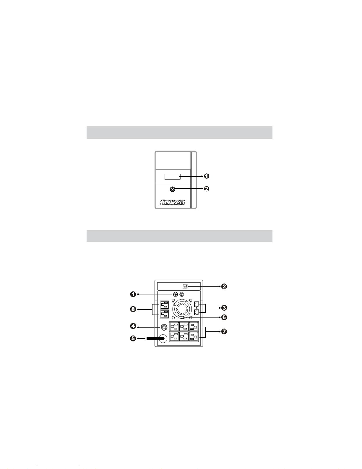
Front panel
1. LCD display
2. Power “on/off” switch
Features
• LCD displays real time status information
• Easy to read LCD display with bright blue backlight
• Power protection for home and office equipment
• Boost & buck AVR to stabilize voltage
• 8 outlets - Six (6) with surge protection, battery backup and AVR, plus two (2)
surge only outlets
• Network, phone, fax & modem protection (RJ-45/11)
• USB communication port
• Long back-up time
• Power management software CD
• 660-joule surge rating
• Coaxial protection
Back panel
1. Coaxial lines
2. USB data port
3. Network, telephone, fax & modem
protection (RJ-45/11)
4. User-resettable circuit breaker
5. AC power input
6. Cooling fan
7. Six (6) outlets with surge protection,
battery backup and automatic voltage
regulation (AVR)
8. Two (2) surge-only protected outlets
Installation and operation
1. Inspection
Remove the UPS from its package and look for damages that may have occurred during
shipping. If any damage is discovered, repack the unit and return it to the place of purchase.
2. Choose location
Install the UPS unit in any protected environment that provides adequate airflow around the
unit, and free from excessive dust, corrosive fumes and conductive contaminants. Do not
operate your UPS in an environment where the ambient temperature or humidity is high. Place
the UPS unit at least 20cm away from monitors to avoid interference.
FX1500LCD / FX2200LCD
FX1500LCD-U / FX2200LCD-U
FX1500LCD / FX2200LCD
FX1500LCD-U / FX2200LCD-U
Page 4
3. Charge the UPS
This unit is shipped from the factory with its internal battery fully charged; however, some
charge may be lost during shipping. Therefore, it is recommended to charge the battery prior
to initial use. Simply plug the unit into an appropriate AC outlet, and allow it to recharge to full
capacity for at least 8 hours.
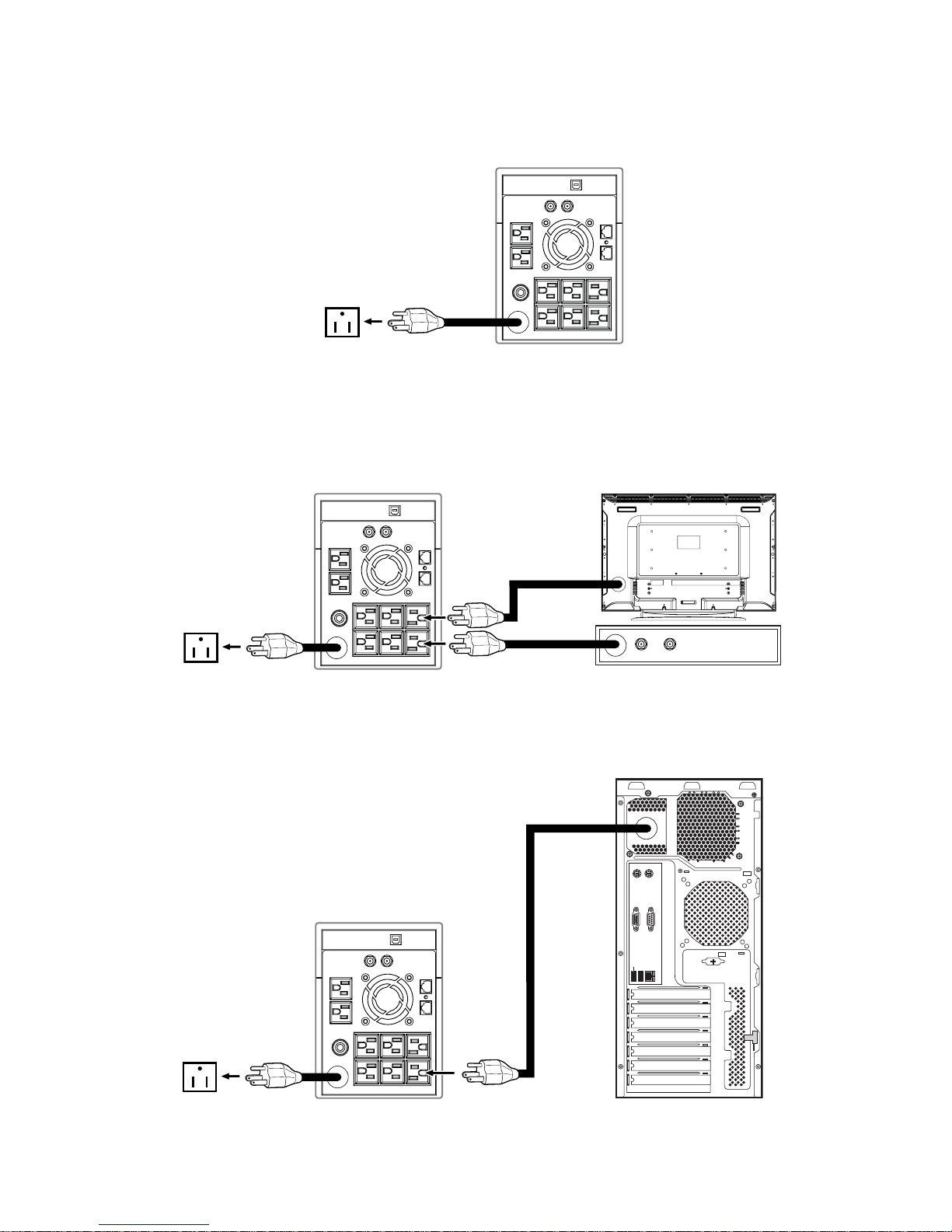
4. Connect to home theater or server PC
Connect your TV/receiver or computer-related device into each power receptacle supplied on
the back of the UPS, as shown below.
Home theater
Server/PC
ANTENNAINANTENNA
OUT
TV
SATELLITE / CATV / CABLE MODEM
COMPUTER
Page 5
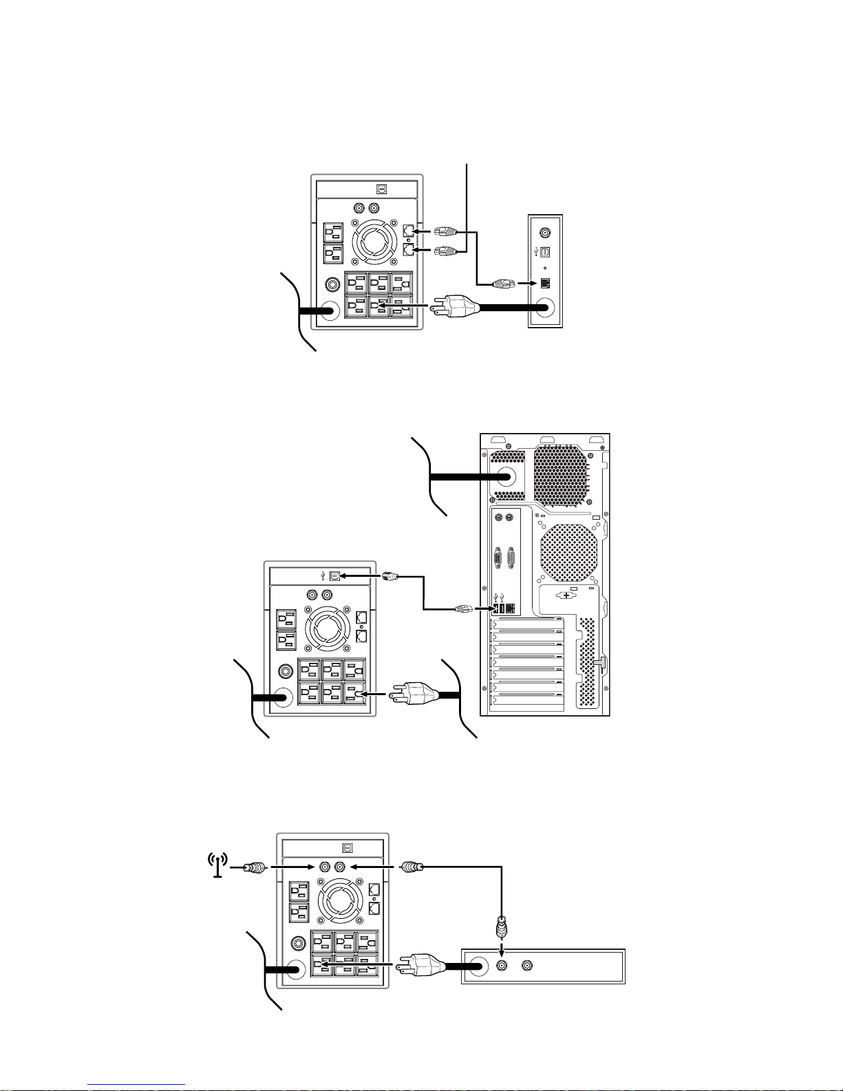
5. Network/Modem/Phone line connection
Connect the incoming internet line into the input surge protected jack on the back of the UPS.
Then connect another network cable from the output jack on the UPS to the modem input
socket, as shown in the figure below.
6. USB data cable connection (only for server/PC connections)
To enable unattended system shutdown via power monitoring software, connect the USB as
shown in the diagram below.
7. Coaxial line connection
Connect your incoming cable/antenna, digital satellite system line to the input connector on
the UPS. Connect the coaxial cable into the output connector on the UPS, and then plug the
other end of the coaxial cable to the input connector of the device you want to protect. (Coaxial
cable not included).
CABLE / ANTENNA
RESET
ETHERNET
USB
CABLE
ANTENNAINANTENNA
OUT
NETWORK / PHONE LINE
MODEM / SWITCH / ROUTER
COMPUTER
SATELLITE / CATV / CABLE MODEM
Page 6

8. Turn On/Off UPS
Press and hold the power switch on the front panel to start the UPS. The LED lights up when
switch is on. To turn the unit off, simply press and hold the power button until the LED goes off.
9. DC start function
DC Start Function enables UPS to be powered up when AC utility power is not available and
battery is fully charged. Simply press the power switch to turn on the UPS.
10. LCD display
The Forza 1500/2200LCD/LCD-U Series comes equipped with an easy to read LCD and a
blue backlight that displays the battery status, input voltage, output voltage, and operation
mode of the UPS.
When the LCD is initially powered on, the
LCD will display all information at once.
1). When operating in normal mode, the
display appears as shown below.
2).When in AVR mode, it will display as
below. And the mark
will blink once
every second.
3).When in battery mode, it will display as
below. And the mark
will blink once every
second.
Note: If I/P-V<40V, input voltage will be
displayed as 000
4).When in off / charging mode, it will
display as below.
Note: the output voltage will always be
displayed as 000 when in off/charging mode.
5).When in fault mode, the display appears
as shown below. Only the FAULT indicator
and the reason of the malfunction will be
displayed in this case.
Note: a fault code will appear every time the
UPS enters into the fault mode.
Load
LEVEL
Load bar Battery
\
LEVEL
0%~25%
25%~50%
50%~75%
75%~100%
AC mode
Battery voltage <22.0V Battery voltage <25.4V
Battery voltage 25.4V
Battery voltage 26.4V
Battery voltage 27.0V
Battery voltage 22.0V
Battery voltage 23.0V
Battery voltage 25.0V
Backup mode
indication
INPUT/BATTERY
(Unit: VDC/Hz/VAC)
OUTPUT/LOAD/FAULT
(Unit: %/Hz/VAC)
LOAD LEVEL
BATTERY CAPACITY
LINE MODE (AVR)
BACKUP MODE
8.) When in overload condition, the icon blinks once every second.
9). When battery is low, the icon blinks once every second.
Page 7
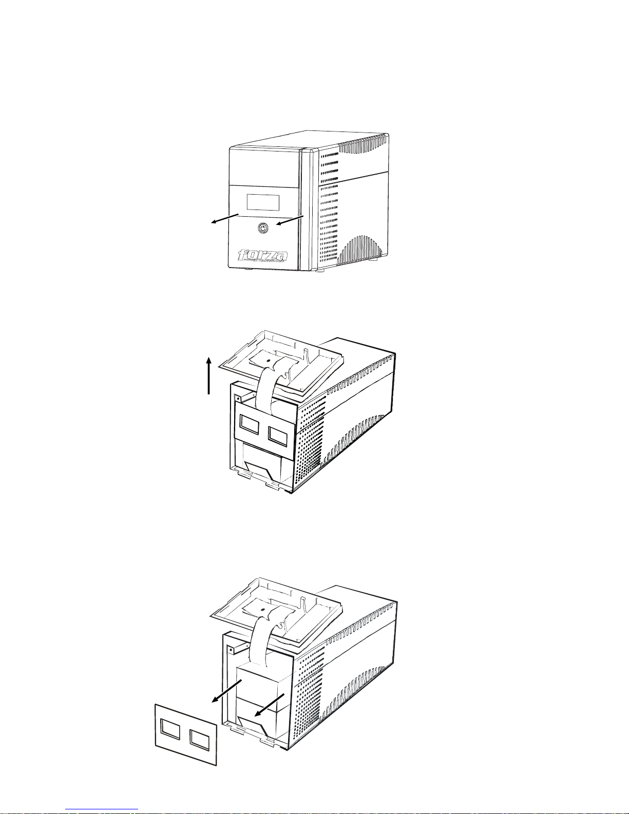
Battery removal*
Follow the steps 1 to 3 to replace the batteries. Disconnect all sources of power before
replacing the battery.
1.
Remove the front panel.
2.
Remove the battery cover.
3.
After removing battery cover, gently extract the battery by disconnecting the two wires
connected to the UPS. Be sure to replace the same type of batteries and dispose of old
batteries properly at an appropriate recycling facility.
*Battery removal by technician recommended.
Page 8
The UPS does not turn on and no LED display
Possible Cause Solution
Low battery voltage Charge battery for at least 8 hours
The battery is defective Replace it with the same type of battery
Power switch is not in the depressed position Press the power switch again
Audible alarm buzzer beeps continuously when AC input line is normal
Possible Cause Solution
The UPS is overloaded Verify that the load matches the UPS capability specified in the specs
When power fails, the backup time is shortened than the normal status
Possible Cause Solution
The UPS is overloaded Remove the least critical load
Low battery voltage Charge battery for at least 8 hours
Battery failure due to high temperature or degraded performance Replace it with the same type of battery
Communication lost between UPS and computer
Possible Cause Solution
Software is not installed correctly. Check the settings of the software.
Cable is not properly connected. Check the USB cable is firmly connected to
COM1/COM2 of the computer and confirm the setting again.
Even when mains supply is normal, the LED still displays battery mode
Possible Cause Solution
Circuit breaker trips Reset the circuit breaker.
Power cord is loose. Reconnect the power cord properly.
* For further assistance, please contact us at [email protected]• When replacing your batteries, we recommend using a Forza FUB-1290.
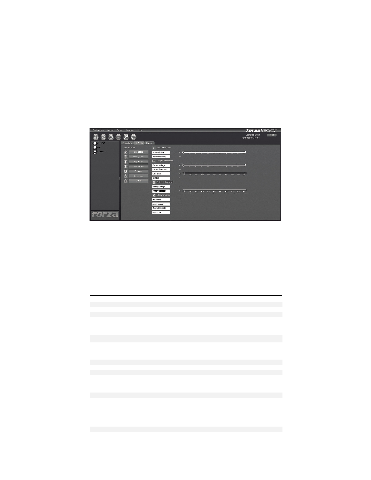
Software installation
ForzaTracker is a new generation of UPS monitoring software, which provides user-friendly
interface to monitor and control your UPS system. This unique software provides safe auto
shutdown for multi-computer systems during power failures. With this software, users can
remotely monitor and control any UPS on the same LAN, no matter how far the unit is located.
Installation procedure:
1. Go to the website: http://www.forzaups.com/us/driver-downloads/
2. Choose the type of operation system and follow the instructions on the website to
download the software.
3. When downloading all required files from the internet, enter the serial No: 5242-87f6-64re-
di8d-986u to install the software (including hyphens).
4. When your computer restarts, the management software will appear as a green plug icon
located in the system tray, near the clock.
5. To access the Forza Tracker management software as an administrator, you must enter the
password: 111296
Troubleshooting guide
When the Forza UPS is not working normally, please refer to the following trouble shooting
table for solving installation or operation problems. If any abnormal situation not listed above
occurs, please call our service department for further assistance.
Page 9
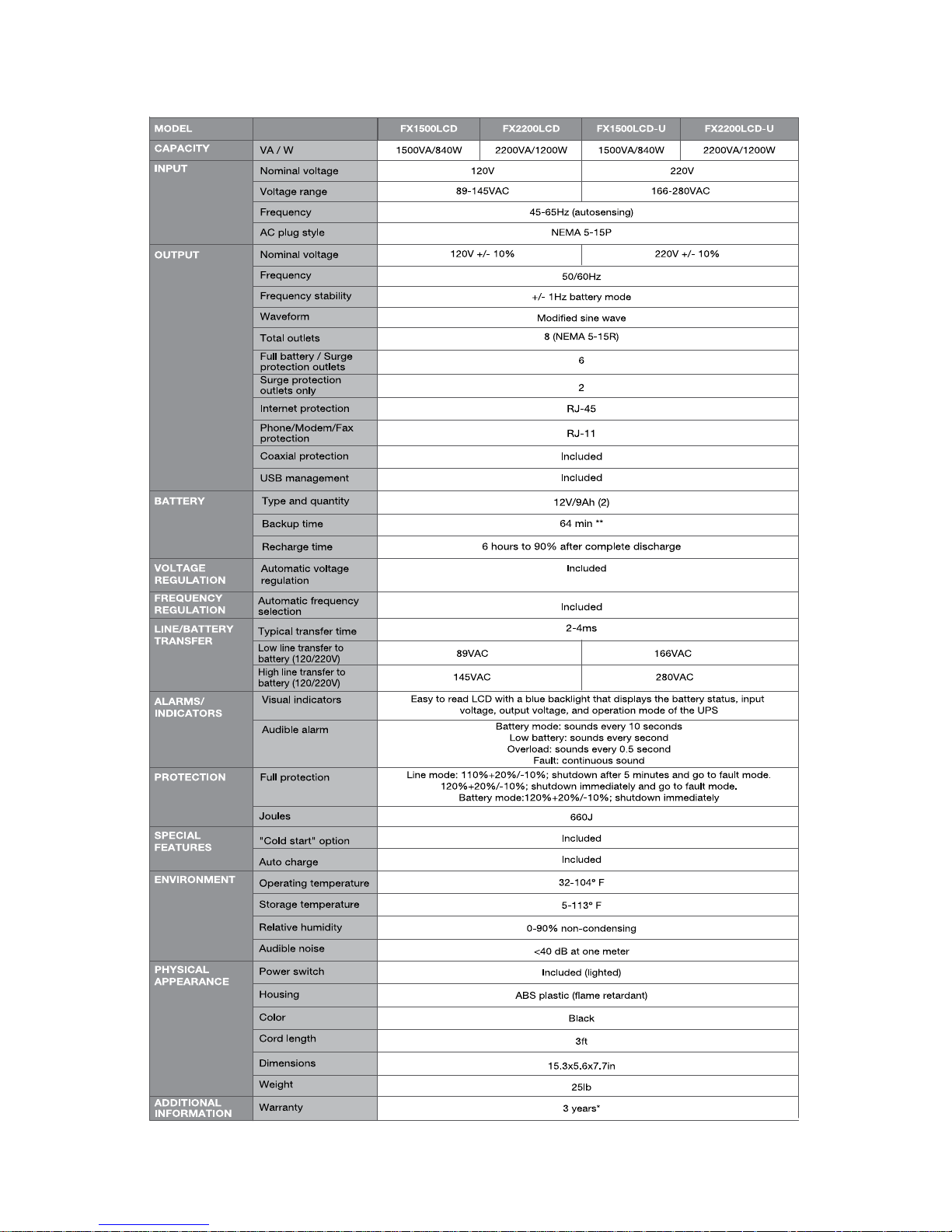
Technical specifications
* 2 years on batteries
**Calculated with a single PC plus monitor
Page 10

Forza Power Technologies, LLC Forza® is a registered
trademark. All rights reserved.
Reproduction of this manual or any part thereof is forbidden
without written consent from Forza Power Technologies, LLC.
All other trademarks and brand names are registered
trademarks of their respective owners. Any mention of such is
only intended for identification purposes, and therefore shall not
be construed as a claim to any or all rights pertaining to those
brands. Specifications are subject to change without notice.
Made in China.
 Loading...