

Page 1
4ZA OWNERS MANUAL
4ZA OWNERS MANUAL FOR FAST FORK RACE
Page 2
GENERAL
Read this manual carefully before using your 4ZA FAST fork and setting up the integrated brakes.
This complex and technically advanced product requires the highest attention during installation.
WARNING Bicycle riding can be, and often is, extremely dangerous. Your 4ZA FAST fork was designed
and manufactured using state of the art technology and materials. It meets and exceeds the current ENstandard which apply to the product.
Nevertheless, the poor condition of many of our roads, your speed on impact, dangerous climatic conditions,
your weight and your dexterity as a rider are just a few of the factors which contribute to possible and even
foreseeable impact energies well beyond your 4ZA FAST fork capabilities. No fork, including your 4ZA FAST
fork, can withstand ALL such foreseeable impacts.
WARNING Your 4ZA FAST fork is a high-tech product and must therefore be assembled only by a specialized mechanic using sophisticated, professional tools. DO NOT ATTEMPT TO ASSEMBLE YOUR
4ZA FAST FORK YOURSELF! Should you decide to disregard our recommendation, please follow the
assembling instructions featured in this owner’s manual very carefully and remember that you are doing so at
your own, exclusive risk!
WARNING Your 4ZA FAST fork can be used for road racing or triathlon only!!!!
WARNING In the event of a crash, even a minor one, immediately take your bike to a specialized 4ZA
dealer and have the integrity of your FAST fork checked for possible damage. Failure to do so may result in
injury or death.
WARNING Make sure you thoroughly check every component of your bicycle paying particular attention
to your 4ZA FAST fork before each and every single use. Make sure there are no cracks or deformations.
Should you fi nd any, do not use your bicycle. Take it to a professional mechanic for any and all necessary
repairs/replacements.
WARNING Make sure you submit your 4ZA FAST fork for regular check-ups by your mechanic. It has
been our experience that a large majority of accidents could have easily been avoided by a preliminary
examination by a professional mechanic.
WARNING 4ZA declines any and all responsibility for injuries and/or damages caused by the failure to
scrupulously respect the instructions on torque values in tightening the bolts. Any different torque measurements can and will affect the integrity of your 4ZA FAST fork.
WARNING Never dispose any of your 4ZA components in the environment. Seek the advice of your local
waste collection offi cials.
TECHNICAL INFORMATION
Fork dimensions
The 4ZA FAST fork is designed for use with tapered headsets compatible with a 1-1/2” lower fork steerer
diameter and 1-1/8” upper fork steerer diameter.
The tapered part of your 4ZA FAST fork is 70mm long. Make sure that the head tube of your frame is long
enough to assemble the fork.
Clearance
The integrated brake of the 4ZA FAST fork can accommodate wheels with the a max. brake track width of
23mm and a maximum rim width of 28mm.
The FAST fork can accommodate road clincher tires with a dimension up to 700x25c. Wider tires will not
provide the required lateral and radial tire clearance in the fork crown area.
Serial number
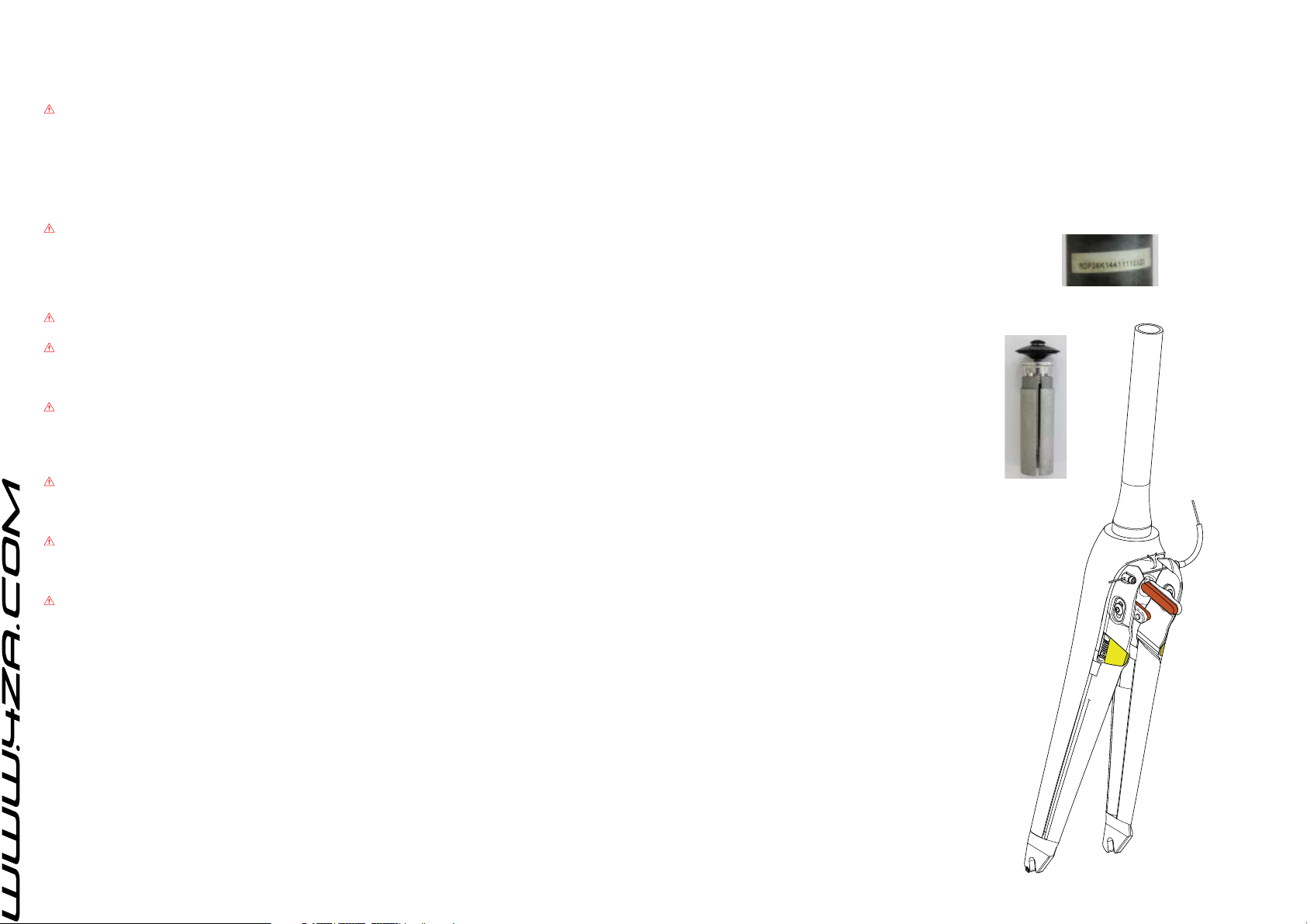
The serial n° of your 4ZA FAST fork can be found on the steerer tube.
PARTS AND TOOLS
Provided with the fork
• Owner’s manual
• 4ZA expansion plug for carbon fi ber steerer tube.
• Brake pads
• Brake adjustment spring
• Micro adjuster (for centering the brake arms)
• Foam cover
• Cable Fixation
• 4ZA Quick
• Inline adjuster
Tools needed
• 2, 4, 5, 6 mm Hex wrenches
• Needle nose pliers
• Torque wrench
• Grease or titanium anti-seize for titanium bolts
• Isopropyl alcohol
• 400 grit sandpaper
• Crown race installation tool
• 28 tooth (minimum) blade saw
• Masking tape
4ZA expansion plug
TABLE OF CONTENTS
• General safety warnings
• Parts and tools
• Technical information
• Preparation
• Fork installation
• Brake setup
• User instructions
• Maintenance
• Information
Page 3
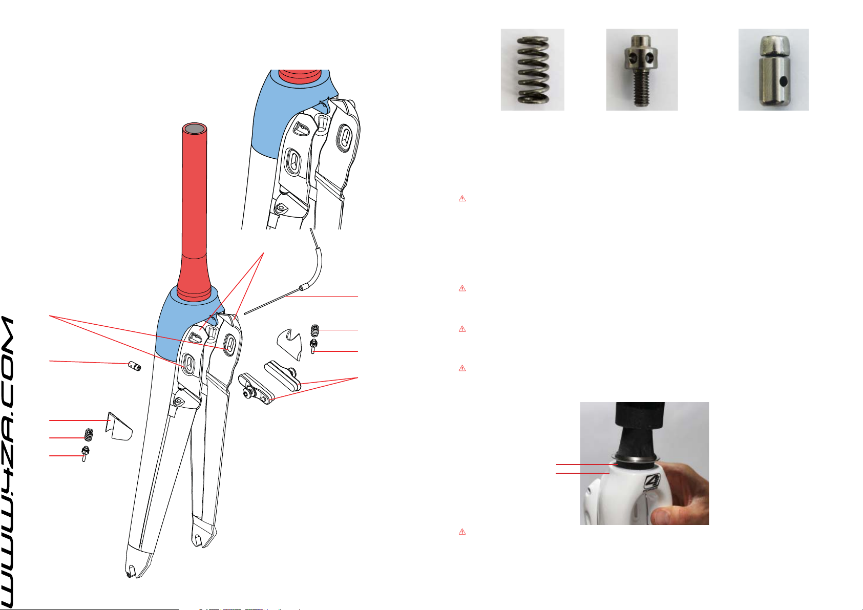
4ZA FAST fork parts
Familiarize yourself with the parts of your 4ZA FAST fork and the tools required to assemble the FAST fork in
your bike.
(In Red) Fork steerer tube
(In Blue) Fork crown
(A) Integrated brake arms
(B) Brake pad slot
(C) Brake pads
(D) Brake adjustment spring
(E) Micro adjuster
(F) Foam cover
(G) Cable Fixation
(H) Brake inner wire
4ZA Quick
TECHNICAL INFORMATION
Important! Verify that the fork and the headset have compatible diameters.
Fork crown race diameter: 39,8mm
The fork steerer tube has a diameter of 28,6mm.
The fork is compatible with frames that feature a 1-1/2” lower bearing and 1-1/8” upper bearing.
Important! Verify that the stem steerer clamp diameter is compatible with the fork steerer tube diameter.
WARNING: THE FORK, HEADSET AND STEM STEERER CLAMP MUST HAVE COMPATIBLE DIAM-
ETERS. INCORRECT MATCHING OF COMPONENTS CAN CAUSE COMPONENT FAILURE.
D
E
G
B
G
F
D
E
A
H
D
E
C
PREPARATION
Confi rm the headset parts are free of any burrs or sharp edges. Remove any burrs or sharp edges with 400
grit sandpaper.
Confi rm your stem is free of any burrs or sharp edges at the steerer clamp slot. Remove any burrs or sharp
edges with 400 grit sandpaper.
WARNING: ONLY USE A REAR SLOT CLAMP STEM.
FORK INSTALLATION
WARNING: AVOID SCRATCHING OR SCORING THE STEERER TUBE SURFACE. ANY DAMAGE TO THE
STEERER TUBE COULD CAUSE FAILURE.
Apply a small amount of grease to the fork crown race seat.
WARNING: DO NOT MAKE ANY MODIFICATIONS TO THE CROWN RACE AREA OF THE FORK.
Only use a headset race with the correct inside diameter for your fork steerer tube.
Hold one leg of the fork securely and, using an appropriate crown race setting tool, install the fork crown
race.
Crown race
Crown race seat
WARNING: DO NOT PLACE THE FORK ON THE DROPOUT TIPS OR CROWN WHILE INSTALLING THE
FORK CROWN RACE. DOING SO CAN DAMAGE THE FORK AND COULD CAUSE FAILURE.
Page 4
Cutting the steerer tube
WARNING: THE SPACER STACK BELOW THE STEM MUST NOT EXCEED 50 MM.
Measure and cut the steerer tube 3mm below the top of the stem. Apply masking tape at the cut location
to help prevent the carbon from fraying. Use a 28 tooth (minimum) blade saw and cut to the proper length.
Smoothen the entire cut area with 400 grit sandpaper.
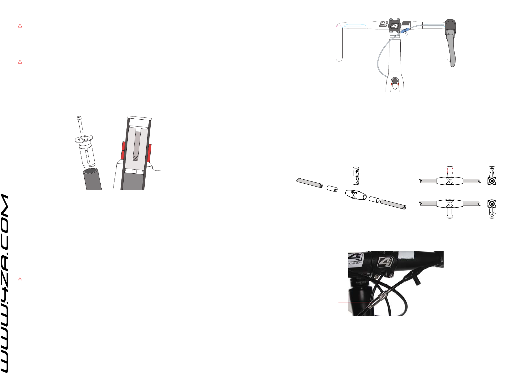
Install the 4ZA expansion plug for carbon fi ber steerer tubes.
WARNING: DO NOT MODIFY THE FORK IN ANY WAY, OTHER THAN CUTTING THE STEERER TUBE TO
THE CORRECT LENGTH FOR YOUR BIKE.
MODIFYING THE FORK COULD CAUSE FORK OR OTHER COMPONENT FAILURE RESULTING IN SERIOUS INJURY OR DEATH.
Installing the 4ZA expansion plug
Remove the top cap bolt using a n°5 Allen key. Now take a n°6 Allen key to tighten the bolt of the expansion
plug. Keep tightening it until it slide-fi ts in the steerer tube. The collar of the expansion plug must rest on top
of the cut steerer tube. Tighten until the plug is fi rmly fi xed and can no longer move inside the steerer tube.
HEADSET SPACERS
Assemble the fork, tapered headset and any spacers in the head tube of the bicycle.
Stem Installation
Carefully install your 4ZA stem and stem top cap on the fork steerer tube, in line with the front wheel.
Important! Follow your headset manufacturer’s instructions for proper installation of the headset compres-
sion device. Align your 4ZA stem to the bike, then preload the headset by installing the top cap bolt to the
torque specifi ed by your headset manufacturer’s instructions.
Head-stem compression bolt should be tightened in a way that there is no noticeable tolerance on the headset when moving the fork. Use a torque wrench to tighten the steerer clamp bolt(s), in increments of one full
turn, in an alternating fashion, to 5N/m (44,25 in-lb).
BRAKE SETUP
WARNING: FAILURE TO PROPERLY INSTALL AND ADJUST BRAKES CAN RESULT IN SERIOUS INJURY
OR DEATH.
4ZA Quick installation
4ZA’s Quick allows the rider to open his/her brakes while keeping hands on top of the handlebar.
The Quick consists out of 2 parts. The body (placed in-line with the cable housing) and the slider to open/
close the brake.
The cable routing and shape of the handlebar will determine where the Quick is assembled. Different handlebars might result to different positioning methods.
Use a marker to indicate where the 4ZA Quick will be located. Choose a location making it easy to operate
the 4ZA Quick so that you can reach it with your hands on top of the handlebar.
Cut the brake housing at the mark of your indication. Use an awl to open the end of the housing. Finish this
step off by assembling the proper end caps (3).
The correct assembly of the slider is crucial. It must be assembled in the closed position.
OPEN
2
4
3
1
(1 = Quick body, 2 = Quick slider, 3 = end caps for cable housing, 4 = brake housing)
Install the inline adjuster.
Installation of the inline adjuster is optional. Giving riders easy and safe access for the brake adjustments they
need to make on the fl y.
3
4
CLOSED!!!
Assembly of the brake housing
Take the brake cable housing, install the cable end cap and place the cable end in the brake arm.
Let the brake cable housing pass in front of the head tube making a short bend and lead it over the handlebar to the control lever. Tape the housing to the handlebar and cut to the desired length.
Important! Do not try to bend the brake housing too close the frame head tube. This will displace the brake
arm and infl uence the brake setup.
Inline adjuster
Page 5
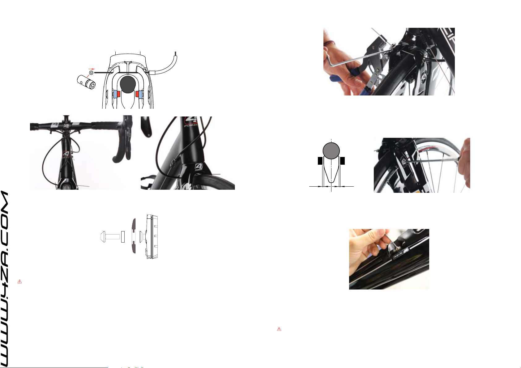
Install the brake cable
Install the brake cable through the front of the brake lever and pull through. Feed the inner brake cable
through the upper part of the brake housing and the Quick Body. Slide the lower part of the cable housing
onto the brake inner wire.
Run the brake cable through the top opening of the brake arms. Loosen the nut of the cable fi xation and slide
it over the brake cable until it touches the brake caliper.
The setup should look as follows.
Brake setup
Use a cable stretcher to pull cable length until the brake pads make contact with the rim brake track.
Important! Ensure that the pad contact with the brake track surface is fl at.
Important! Ensure that both brake pads are properly aligned in reference to each other.
Important! Ensure that both brake pads are aligned parallel to the rim.
Tighten the brake pad adjustment bolt using a 4mm Hex wrench, release the brake cable inner until each
brake pad is 2mm elongated from the brake track.
Tighten the nut of the cable fi xation for brake cable inner.
Brake pad installation
Assemble the brake pads and fi x them by hand.
Important! make sure that the washers are installed correctly.
Install the front wheel
Install the front wheel and carefully follow the wheel manufacturer’s instructions for correct clamping of the
wheel quick release.
WARNING: FAILURE TO PROPERLY ADJUST THE QUICK RELEASE AND SECURE THE WHEEL CAN
RESULT IN SERIOUS INJURY OR DEATH.
Make sure that the wheel is centered.
2 2
Squeeze the brake levers hard 3 times and repeat the previous step if necessary.
Cut off excess inner wire and install the a cable end crimp.
Adjust the spring tension of the micro adjusters to center the brake pad on each side of the brake track. The
micro adjuster is operated with a 2mm Hex wrench.
Counterclockwise: the micro adjuster is unscrewed bringing the brake arm closer to the rim.
Important! The micro adjuster can only be unscrewed for max. 4mm
Do not operate the 2 brake adjusters simultaneously, doing so will result in a loss of cable tension
Installation/ replacement of the adjuster springs
The 4ZA FAST fork is sold with the adjuster springs preassembled.
WARNING: We strongly advise that these adjuster springs are installed/replaced by a specialized mechanic using sophisticated, professional tools. DO NOT ATTEMPT TO ASSEMBLE YOUR 4ZA FAST FORK
YOURSELF! Should you decide to disregard our recommendation, please follow the assembling instructions
featured in this owner’s manual very carefully and remember that you are doing so at your own, exclusive risk!
Page 6
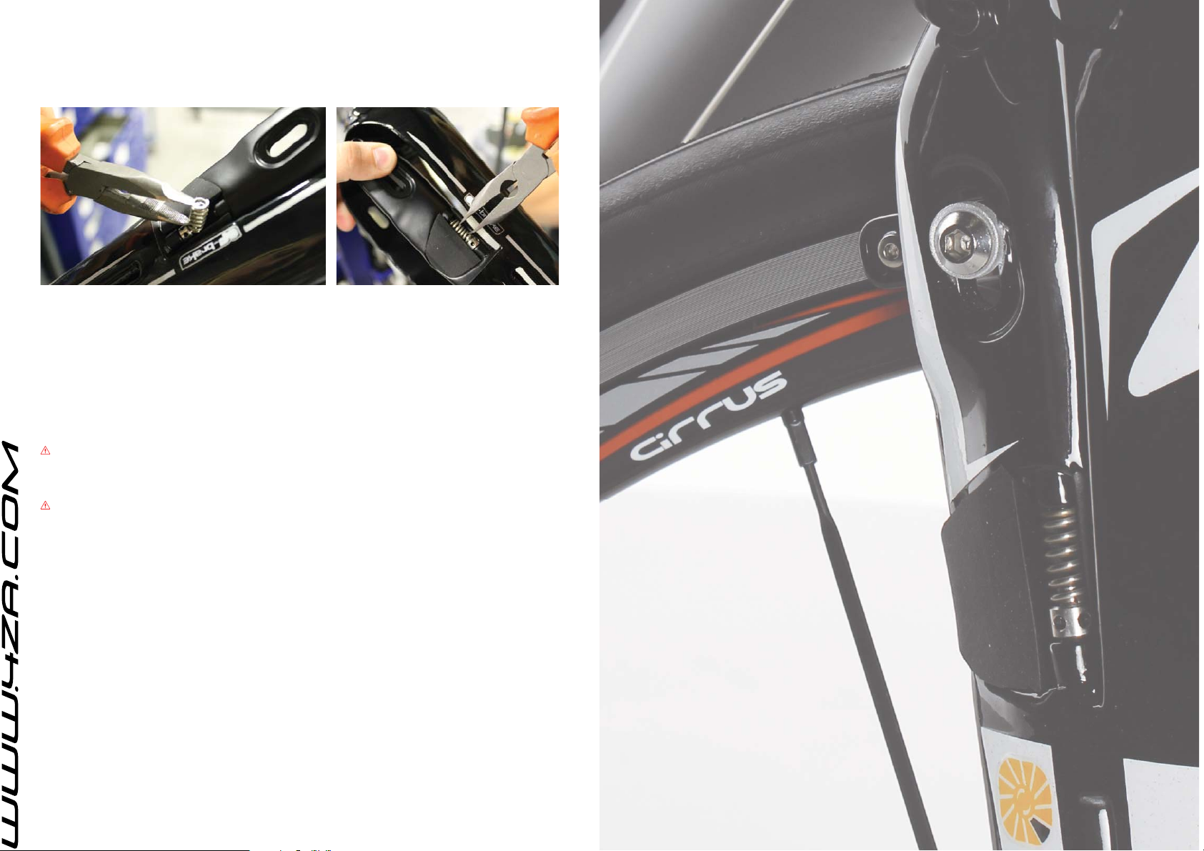
Place the micro adjuster in the threaded seat and screw it in over its maximum depth using a 2mm Hex
wrench.
Use needle nose pliers to compress the adjuster spring. Press the brakearms together using your hands.
Install the spring between micro adjuster and the upper stopper. Release the tension from the brake arms.
Retract the needle nose pliers.
USER INSTRUCTIONS
Fork Alignment
Always loosen the stem’s steerer clamp bolts before attempting to make stem/fork alignment adjustments.
Bicycle rack
When using a dropout clamping bicycle rack, always clamp the dropouts securely to prevent dropout and/or
bike damage. If the clamp is loose, the bike may fall out of the rack. When removing the fork from the clamp,
be sure to remove both dropouts evenly at the same time. Do not tilt the bike to one side, because dropout
damage can result.
WARNING: DROPOUT DAMAGE CAN CAUSE COMPONENT FAILURE, WHICH CAN RESULT IN SERI-
OUS INJURY OR DEATH.
Dropout safety tab
WARINING: REMOVING THE DROPOUT SAFETY TAB FOR THE FRONT FORK IS PROHIBITED. THE
WARRANTY IS NO LONGER VALID WHEN REMOVED. THESE SAFETY TABS ARE CRUCIAL TO THE
RIDERS SAFETY THEY ARE DESIGNED TO KEEP THE FRONT WHEEL IN THE DROPOUTS EVEN IF THE
QUICK RELEASE OPENS.
MAINTENANCE
Make sure you submit your 4ZA components for regular check-ups by your mechanic. It has been our
experience that a large majority of accidents could have easily been avoided by a preliminary examination by
a professional mechanic. Clean your 4ZA components using only water and mild soap. Regularly inspect the
bolt torque. You should never ride with any of your 4ZA components loose. Regularly inspect components
for signs of damage or fatigue. Always inspect components for damage after any crash. Signs of damage or
fatigue include, but are not limited to cracks, dents, deformation, discoloration, deep scratches, or audible
creaking. Discontinue use and replace any parts that show signs of damage or fatigue. Do not attempt to
repair parts. If you are unsure of the integrity of your 4ZA component, have it inspected by your 4ZA dealer.
INFORMATION
4ZA reserves the right to modify this owner’s manual. Such possible modifi cations will be listed on 4ZA’s
internet site (http://www.4za.com) and/or are available by contacting us at 4ZA and/or your authorized 4ZA
retailer. Make sure you periodically check any one of these three sources of information for possible modifi cations to this owner’s manual.
NV Race Productions | 4ZA
Beverlosesteenweg 85 | 3583 Paal-Beringen | Belgium
 Loading...