

Page 1

Skiving Machine ES 50
Operating Manual
English, Version 03
Page 2

Copyright
FORTUNA Spezialmaschinen GmbH, Weil der Stadt, Germany
The German Operating Manual is the original and form the basis for all
translations.
Without our prior written consent, these instructions may neither be
translated, passed on to third parties nor be reproduced or distributed in
any way. Contravention will result in prosecution under existing laws.
All rights reserved, in particular in the case of patents issued.
©2010 FORTUNA Spezialmaschinen GmbH
Operating Manual part number: ES 50-BA-UK-V3
Version: 03
Date of issue: 24.01.2012
FORTUNA
Spezialmaschinen GmbH
Eisenbahnstraße 15
D-71263 Weil der Stadt
Germany
Managing Director: Narith Meksavanh
———————————————————————————–––––––––––––––––––––––––
Operating Manual Skiving Machine ES 50-UK-V3/24.01.2012 2 von 45
Page 3

Customer information
The Operating Manual has specially been compiled for the FORTUNA
Skiving Machine ES 50.
It consists of:
Machine description
User manual
The instructions must be read carefully and the reader must thoroughly
familiarise themselves with all details. Failure to comply with the
instructions in the documentation may result in a loss of warranty in case of
damage.
In addition to the Operating Manual, the generally applicable regulations as
well as the domestic and local regulations on accident prevention and
environmental protection must be made available and observed.
To help you understand your FORTUNA Skiving Machine ES 50, design
details are given, some of which are confidential. This information is
intended only for the operator of the machine and may be neither
reproduced nor made accessible to third parties.
We are certain that your new FORTUNA Skiving Machine ES 50 will
completely meet your expectations.
If you have any further questions, the FORTUNA advisory service
engineers are always available to provide additional information.
———————————————————————————–––––––––––––––––––––––––
Operating Manual Skiving Machine ES 50-UK-V3/24.01.2012 3 von 45
Page 4

Summary of customer documentation
Machine description
Among other things the machine description comprises:
Machine data
Safety information
Important safety devices
Personnel (demands and duties)
Machine installation
User manual
The machine's user manual contain all the information necessary to
operate your FORTUNA Skiving Machine ES 50. They must be given to the
operator of the machine. These user manual must always be available at
the machine.
All safety information, regulations and demands stipulated in the “ Machine
description “ section also apply to operations with the machine.
Repair Manual
The Repair Manual contains all information necessary to replace wearing
and spare parts on your Skiving Machine ES 50.
This document must be handed to the member of staff who repairs the
machine. Staff entrusted with this task must be trained by FORTUNA
Spezialmaschinen GmbH.
All safety information, regulations and demands stipulated in the “ Machine
description “ section also apply to the repair and replacement of parts.
Spare parts list
The spare parts list contains all the information on the machine's individual
components and assemblies.
Circuit diagram
———————————————————————————–––––––––––––––––––––––––
Operating Manual Skiving Machine ES 50-UK-V3/24.01.2012 4 von 45
Page 5

A
B
C
D
Table of content
E
Table of contents
1 Machine description ................................................................................... 7
1.1
Machine data ......................................................................................... 7
1.1.1 Range of application of the machine ............................................... 8
1.1.2 Technical data ................................................................................. 9
1.1.3 Electrical data .................................................................................. 9
1.1.4 Ambient conditions .......................................................................... 9
1.1.5 Tools and accessories ................................................................... 10
Applicable rules and regulations .......................................................... 11
1.2
Guarantees and liabilities .................................................................... 12
1.3
Copyrights ........................................................................................... 13
1.4
Training offers ...................................................................................... 14
1.5
CE declaration of conformity ............................................................... 15
1.6
Safety information ................................................................................ 16
1.7
1.7.1 Personal safety .............................................................................. 17
1.7.2 Safety in the operation area .......................................................... 17
1.7.3 Safety rules for the use of tools ..................................................... 17
1.7.4 Safety rules for the transport ......................................................... 18
1.7.5 Safety rules for the installation and operation of the machine ....... 18
1.7.6 Safety rules for repair and maintenance work ............................... 19
1.7.7 Inspection requirements ................................................................ 20
1.7.8 Further safety rules ........................................................................ 20
1.7.9 Symbols and reference marks ....................................................... 21
Important safety devices ...................................................................... 22
1.8
1.8.1 Main switch .................................................................................... 22
1.8.2 Motor protection switch .................................................................. 22
1.8.3 Protection switch against non-intended restart of the machine ..... 22
1.9
Personnel (requirements and tasks) .................................................... 23
1.9.1 Operators ....................................................................................... 24
1.9.2 Repair and maintenance personnel ............................................... 24
1.10
Installation of the machine ................................................................... 25
1.10.1 Transport ....................................................................................... 25
1.10.2 Unpacking the machine ................................................................. 25
1.10.3 Installation of the machine ............................................................. 26
1.10.4 Preliminary work for start-up .......................................................... 26
1.10.5 Electrical connection ...................................................................... 27
Start-up ................................................................................................ 28
1.11
1.11.1 Installation of the regulator pedal .................................................. 28
2 User manual .............................................................................................. 29
Main switch .......................................................................................... 29
2.1
Explanation of the control elements .................................................... 30
2.2
2.2.1 Adjusting screw for adjusting the skiving thickness ....................... 30
2.2.2 Knurled screw for adjusting the skiving angle ............................... 30
———————————————————————————–––––––––––––––––––––––––
Operating Manual Skiving Machine ES 50-UK-V3/24.01.2012 5 von 45
Page 6

Table of content
2.2.3 Stop for adjusting the skiving width ............................................... 31
2.2.4 Adjusting spindle for adjusting the grinding intensity ..................... 31
2.2.5 Adjusting screw for dressing the grinding wheel ........................... 31
2.2.6 Opening for blunting and deburring the bell knife .......................... 32
2.2.7 Adjusting screw for adjusting the contact pressure of the feed roll 32
2.2.8 Adjusting screw for adjusting the feed roll distance ....................... 32
2.2.9 Adjusting spindle for the knife infeed ............................................. 33
2.2.10 Setpoint potentiometer .................................................................. 33
2.2.11 Regulator pedal ............................................................................. 33
2.2.12 Handle ........................................................................................... 33
Adjustment of the knife position indicator ............................................ 34
2.3
Adjustment of the feed regulator ......................................................... 36
2.4
Cleaning .............................................................................................. 38
2.5
2.5.1 Daily cleaning ................................................................................ 38
2.5.2 Weekly cleaning ............................................................................ 39
2.6
Maintenance work ............................................................................... 40
2.6.1 Troubleshooting ............................................................................. 41
2.6.1.1 Bad skiving results ................................................................. 41
2.6.1.2 Insufficient feeding ................................................................. 41
2.6.1.3 Bevels are too thick ............................................................... 41
2.6.1.4 Insufficient scrap removal ...................................................... 42
2.6.1.5 Noisy operation ...................................................................... 42
2.6.1.6 Electrical troubles .................................................................. 42
2.6.2 Cleaning and maintenance schedule ............................................ 43
Views and detailed drawings ............................................................... 44
2.7
A
B
C
D
E
List of figures
Figure 1: View of the machine ...................................................................... 7
Figure 2: CE declaration of conformity ....................................................... 15
Figure 3: Safety informations and nameplate on the machine ................... 16
Figure 4: Installation plan of the machine ................................................... 26
Figure 5: Mains connection cables of the machine .................................... 27
Figure 6: Knife guidance ............................................................................. 30
Figure 7: Knife position indicator ................................................................ 35
Figure 8: Regulator ..................................................................................... 37
Figure 9: Details of the machine – front view ............................................. 44
Figure 10: Details of the machine – lateral view ......................................... 29
———————————————————————————–––––––––––––––––––––––––
Operating Manual Skiving Machine ES 50-UK-V3/24.01.2012 6 von 45
Page 7
Machine data
—————————————————————————————————————–———
1 Machine description
Machine data
1.1
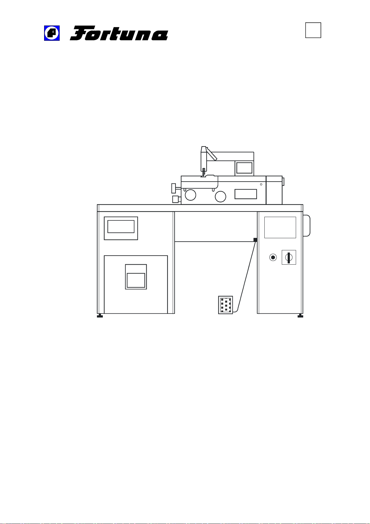
This description of the machine helps you to operate the machine safely
and prevents damage. Please familiarize yourself with the safety
instructions before you transport, connect or start up the machine, see
chapter 1.7 Safety information (page 16).
Figure 1: View of the machine
———————————————————————————–––––––––––––––––––––––––
Operating Manual Skiving Machine ES 50-UK-V3/24.01.2012 7 von 45
Page 8

Machine data
—————————————————————————————————————–———
The guarantee for function and safe operation can only be given in the case
of appropriate operation and the utilization of the original FORTUNA spare
parts.
Check the functioning of all safety devices at regular intervals.
Contact the FORTUNA after sales service immediately if you find out
deficiencies in the safety area.
The operation of the machine must be carried out by skilled personnel only.
The operation of the machine by persons who are younger than 14 years is
not allowed.
The machine is designed to be operated by one person only and must be
used accordingly.
Make sure that the safety devices and control elements are accessible
without restriction during the operation.
1.1.1 Range of application of the machine
This machine is not permitted to be operated in an explosion-proof
area.
Only use this machine for cutting and skiving of leather or material that is
similar to leather (also artificial leather). If you intend to use any other
materials you must contact one of the FORTUNA-representations or the
FORTUNA Company and ask for written approval.
Any other use of the machine may not correspond with the application
range of the machine. The FORTUNA Company is not responsible for any
damages resulting from the non-observance of these rules.
Other considerations for the correct application of the machine are:
the observance of all recommendations in the Operating Manual and
the execution of all prescribed inspection and maintenance tasks.
The use of the following materials is not allowed:
Metals
Wood
Rubber with metallic insert
Hard PVC
Textiles
Glass
Ceramics
Please do not exceed or fall short of the values listed in Chapter 1.1.3
Electrical data (page 9).
———————————————————————————–––––––––––––––––––––––––
Operating Manual Skiving Machine ES 50-UK-V3/24.01.2012 8 von 45
Page 9
Machine data
—————————————————————————————————————–———
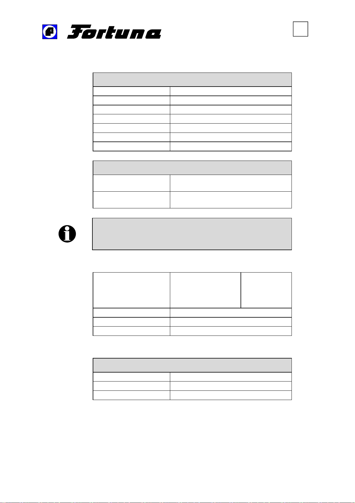
1.1.2 Technical data
Overall Dimensions of the Machine
Width
Required space width
Depth
Required space depth
Height
Weight of the machine
Utilized measuring
device
Value measured at the
operating place
A higher sound pressure level that causes defective hearing can
be generated depending on the local conditions. In this case, the
operating personnel must take protective measures with the
appropriate safety equipment.
1270 mm
1690 mm
565 mm
1115 mm
1200 mm
approx. 170 kg
Noise Emissions
Type ELT 3-215.8510.02
73 dB(A)
1.1.3 Electrical data
Operating voltages and
frequencies
Control voltage 12/220 VAC
Power input 1.0 KVA
Safety fuses max.: 16 A
380 – 420 V 5%
220 – 240 V 5%
380 – 420 V 5%
220 – 240 V 5%
1.1.4 Ambient conditions
Conditions during operation and storage
Humidity < 80 % (non-condensing)
Temperature, stored 0 ... 50 C°
Temperature, operating 10 ... 40 C°
50 cycles
50 cycles
60 cycles
60 cycles
———————————————————————————–––––––––––––––––––––––––
Operating Manual Skiving Machine ES 50-UK-V3/24.01.2012 9 von 45
Page 10

Machine data
—————————————————————————————————————–———
1.1.5 Tools and accessories
Various accessory parts are delivered in the scrap material bin at the front
of the machine.
The following tools are packed in a box
Fork wrench
13 mm x 17 mm
Hexagonal socket-head wrench
2.5 mm / 3 mm / 5 mm
1 Oil stone with sleeve
1 Hex driver with T-handle
1 Set collar A8
Skiving accessories
Presser foot 361 V
Presser foot 361 HP
2 Work plates
Further accessory parts
Key for the switch cabinet
Operating Manual
———————————————————————————–––––––––––––––––––––––––
Operating Manual Skiving Machine ES 50-UK-V3/24.01.2012 10 von 45
Page 11

Applicable rules and regulations
—————————————————————————————————————–———
Applicable rules and regulations
1.2
DIN EN ISO 12100–1 and 12100–2
DIN EN ISO 13857
EC Machinery Directive 2006/42/EG
DIN 60204
DIN EN ISO 13849-1
———————————————————————————–––––––––––––––––––––––––
Operating Manual Skiving Machine ES 50-UK-V3/24.01.2012 11 von 45
Page 12

Guarantees and liabilities
—————————————————————————————————————–———
Guarantees and liabilities
1.3
Our "General sales and delivery conditions" are principally valid for the
guarantee and liability of our products. Personal and material liabilities are
excluded in the following cases:
The machine has been used for purposes other than originally intended.
Improper assembly, start-up, operation and maintenance of the machine.
Operation of the machine with defective safety devices and safety guards
that are not functional or have not been installed in accordance with the
instructions.
Non-observance of the rules that are listed in the Operating Manual with
regard to transport, storage, assembly, start-up, operation, maintenance
and setting-up of the machine.
Unauthorized constructional modifications to the machine.
Unauthorized alterations of the given parameter limits of the machine
(i.e. power, speed and fuses).
Insufficient maintenance of machine parts that are subject to wear.
Non-observance of the prescribed maintenance schedules.
Repair work carried out incorrectly.
Catastrophes caused by external influences or acts of God.
———————————————————————————–––––––––––––––––––––––––
Operating Manual Skiving Machine ES 50-UK-V3/24.01.2012 12 von 45
Page 13

Copyrights
—————————————————————————————————————–———
Copyrights
1.4
The copyrights of this Operating Manual remain in the property of
FORTUNA. They are only intended to be used by the operator of the
machine and his personnel.
Requirements and rules included in these instructions may not be entirely
or partially
copied
distributed or
given to third persons.
Infringements may be prosecuted.
———————————————————————————–––––––––––––––––––––––––
Operating Manual Skiving Machine ES 50-UK-V3/24.01.2012 13 von 45
Page 14

Training offers
—————————————————————————————————————–———
Training offers
1.5
Training possibilities for the Skiving Machine ES 50 are offered at our
Company in Weil der Stadt as well as at our subsidiary companies. Please
inquire about times, subjects and duration of training.
———————————————————————————–––––––––––––––––––––––––
Operating Manual Skiving Machine ES 50-UK-V3/24.01.2012 14 von 45
Page 15
Additionally supplied documents
—————————————————————————————————————–———
CE declaration of conformity
1.6
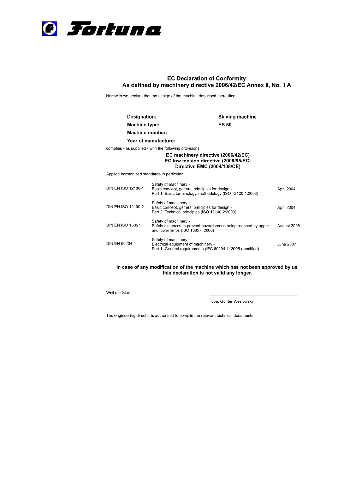
Figure 2: CE declaration of conformity
———————————————————————————–––––––––––––––––––––––––
Operating Manual Skiving Machine ES 50-UK-V3/24.01.2012 15 von 45
Page 16
Safety information
—————————————————————————————————————–———
Safety information
1.7
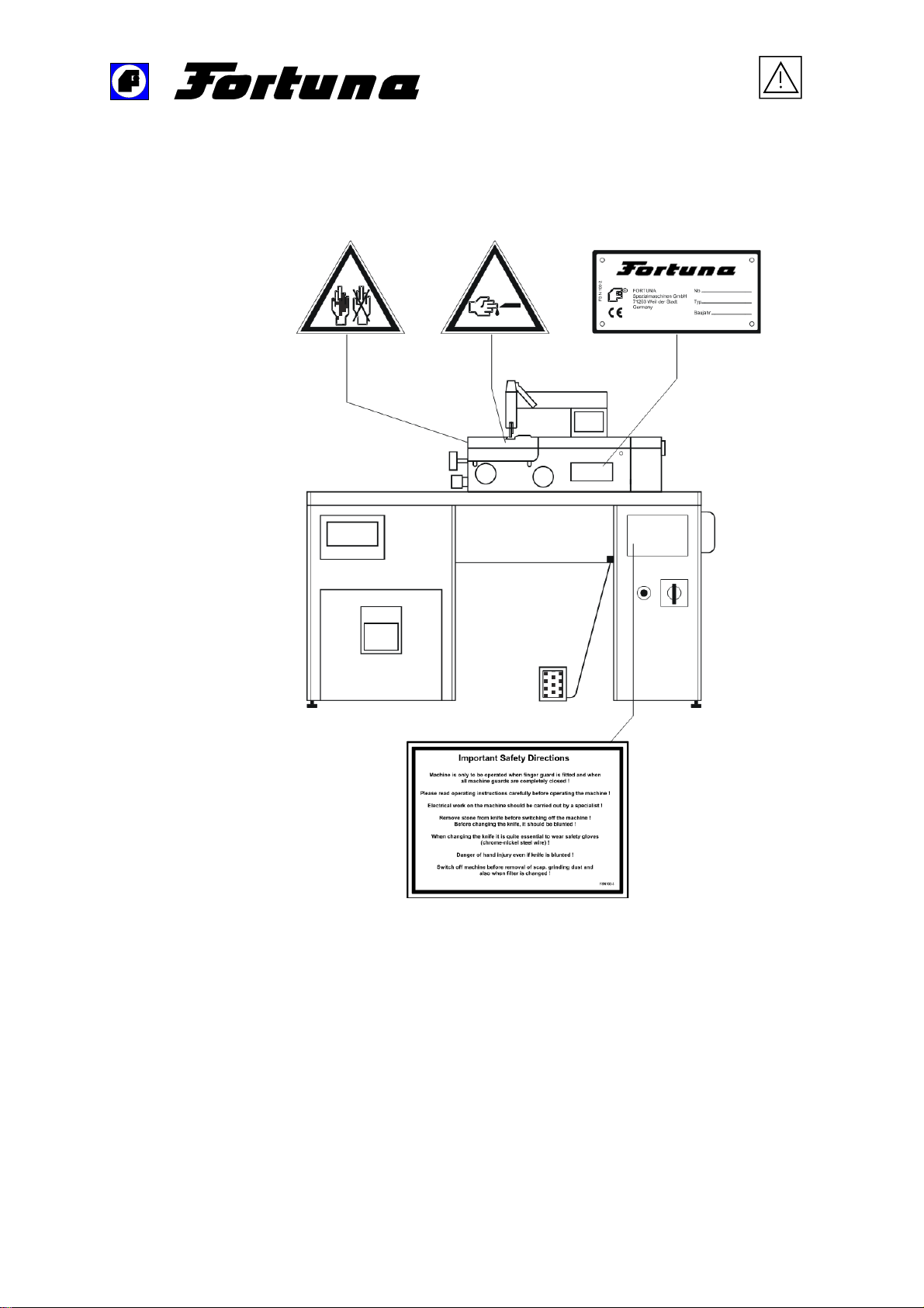
All safety instructions and warnings on the machine must be legible at all
times.
Figure 3: Safety informations and nameplate on the machine
———————————————————————————–––––––––––––––––––––––––
Operating Manual Skiving Machine ES 50-UK-V3/24.01.2012 16 von 45
Page 17

Safety information
—————————————————————————————————————–———
1.7.1 Personal safety
Read and observe the safety rules indicated on the reference plates,
please refer to Figure 3: Safety informations and nameplate on the machine
(page 16).
Use protecting equipment, e. g. steel mesh chain gloves for all work for
which these protections are obligatory.
Do not wear loose clothes. Wear a hair net or bind your hair if your hair is
down to your shoulders. These measures are necessary in order to avoid
any contact with moving machine parts.
Make sure that the main switch as well as the pedal can be reached easily
with your foot during operation.
Inform your company safety representative about all injuries and accidents.
Make sure that the machine is only be operated and maintained by skilled
personnel.
It is not allowed to eat or drink at the place of operation of the machine.
1.7.2 Safety in the operation area
Keep the operation area clean and make sure that the lighting is
satisfactory. Do not keep tools and loose machine parts close to the
machine.
Return tools and equipment to their place after use.
Safety devices must not be bypassed, dismounted or made ineffective by
blocking them.
The machine must only be operated with completely closed cover, filters in
position, scrap material bin closed and knife cover fitted.
1.7.3 Safety rules for the use of tools
Wear gloves and protective clothing when you are working with sharp-
edged cutting tools.
Store the tools (grinding wheels etc.) in the bins that are provided for this
purpose.
Remove hand tools (wrenches, measuring devices etc.) immediately after
use.
———————————————————————————–––––––––––––––––––––––––
Operating Manual Skiving Machine ES 50-UK-V3/24.01.2012 17 von 45
Page 18

Safety information
—————————————————————————————————————–———
1.7.4 Safety rules for the transport
The convenient lifting devices must be used for the installation and
transport of the machine.
Stand clear of the machine when lifting or transporting the machine.
Install safety devices to avoid the machine being dropped.
1.7.5 Safety rules for the installation and operation of the
machine
Read, take care and observe all the safety reference marks on the
machine, please refer Figure 3: Safety informations and nameplate on the
machine (page 16).
Make yourself thoroughly familiar with the different ways of switching off the
machine, Chapter 1.8.1 Main switch (page 22).
Make sure that all safety devices of the machine have been activated prior
to the start-up of the machine.
Do not remove any covers or machine parts during the operation.
Check the tool for wear and damage prior to the start-up of the production
process.
Take care that there are no excessive vibrations and unusual noise during
the operation and maintenance of the machine. They might inform you
about possible problems which require immediate attention.
———————————————————————————–––––––––––––––––––––––––
Operating Manual Skiving Machine ES 50-UK-V3/24.01.2012 18 von 45
Page 19

Safety information
—————————————————————————————————————–———
1.7.6 Safety rules for repair and maintenance work
Work that has to be carried out in the switch cabinet and at the electrical
control system must be carried out by skilled personnel only.
Changes and reconstructions of the machine should be carried out with the
approval of FORTUNA only.
It is not allowed to inactivate safety devices or safety guards or to impair
their effectiveness.
Take utmost care when certain installation work of the machine requires to
switch off safety devices.
You endanger your life if you open the door of the switch cabinet when the
main switch is on.
The power supply to the machine must be interrupted (main switch off)
during the maintenance and cleaning work.
The danger reference marks in the switch cabinet must be strictly observed
(e. g. ‘Attention: machine is voltage-carrying even when the main switch is
off’).
It is obligatory to blunt the knife prior to opening the covering or changing
the knife. Even when the knife is dull there is a risk of injury. Therefore, the
use of steel mesh safety gloves is mandatory.
The machine must be secured (e. g. by locally closing it with a warning
tape) against unauthorized start-up by switching off the main switch when
the machine is left unattended during maintenance work.
Spare parts and replacement parts subject to wear must be examined prior
to their installation and must comply with the manufacturer’s specifications
(this applies specially to knives and grinding wheels).
Appropriate measures must be taken when cleaning and degreasing the
machine with aggressive and inflammable agents.
We recommend that you use only original FORTUNA spare parts.
———————————————————————————–––––––––––––––––––––––––
Operating Manual Skiving Machine ES 50-UK-V3/24.01.2012 19 von 45
Page 20
Safety information
—————————————————————————————————————–———
1.7.7 Inspection requirements
The machine operator is bound to regularly inspect the basic units of the
machine that are important for the operational safety and to replace them in
case of a fault or wear.
The machine is subject to the inspection obligation for electric systems.
The machine must be checked regularly according to the regulations of the
industrial sector and the local regulations.
Obvious damages and the function of the tensioning equipment of the knife,
all drive elements and the guide elements which are in contact with the
knife must always be inspected when the knife is replaced.
The function of the safety switches must be inspected when maintenance
work is carried out.
1.7.8 Further safety rules
During the working process there remains a small risk of injury because
complete protection in the working zone of the knife during the skiving
process of leather parts is not possible.
This zone is marked with a danger label (pictograph). The machine has
been designed for optimum safety in accordance with the latest technical
safety standards.
For further information about safety rules, please refer to this Operating
Manual as well as to the national and international safety recommendations
and laws.
———————————————————————————–––––––––––––––––––––––––
Operating Manual Skiving Machine ES 50-UK-V3/24.01.2012 20 von 45
Page 21
Safety information
—————————————————————————————————————–———
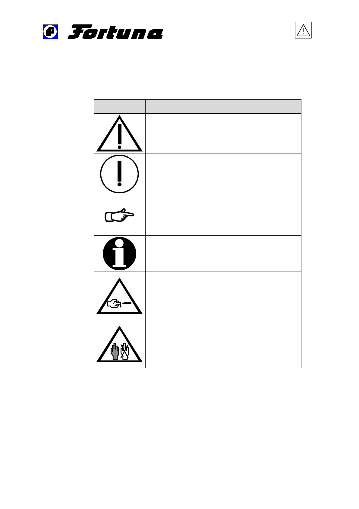
1.7.9 Symbols and reference marks
The following symbols and reference marks will be used in this Operating
Manual and/or are attached at the Skiving Machine ES 50.
Symbol Description
This symbol signifies a direct hazard to life and
health. Non-observance of these directions may be
highly dangerous to your health or result in injuries
that could endanger your life.
This symbol signifies a possible hazard to life and
health. Non-observance of these directions may be
highly dangerous to your health or result in injuries
that could endanger your life.
This symbol refers to the appropriate operation of
the Skiving Machine ES 50.
Non-observance of these directions could result in
a failure of the machine and damage to the
environment.
This symbol refers to a specific operation of the
machine and other relevant information for the
machine.
This symbol signifies that there is an increased
danger of injury from the unshielded knife. It
signifies a direct hazard to life and health.
Non-observance of these directions may be highly
dangerous to your health or result in injuries that
are life threatening.
This symbol signifies that steel mesh chain gloves
must be worn during operation of the machine. It
signifies a direct hazard to life and health.
Non-observance of these directions may be highly
dangerous to your health or result in injuries that
are life threatening.
———————————————————————————–––––––––––––––––––––––––
Operating Manual Skiving Machine ES 50-UK-V3/24.01.2012 21 von 45
Page 22

Safety information
—————————————————————————————————————–———
Important safety devices
1.8
The proper functioning of the safety devices described below must be
checked at regular intervals:
after any repair work,
after any maintenance work and
prior to the start-up of the machine.
1.8.1 Main switch
The main switch stops the drives of the machine; the emergency stop
function separates the machine from the power supply.
1.8.2 Motor protection switch
The motor protection switches in the switch cabinet stop the machine
drives.
1.8.3 Protection switch against non-intended restart of the
machine
The Skiving machine ES 50 is protected against non-intended restart by
means of a self-acting main switch with undervoltage release.
———————————————————————————–––––––––––––––––––––––––
Operating Manual Skiving Machine ES 50-UK-V3/24.01.2012 22 von 45
Page 23
Personnel
—————————————————————————————————————–———
Personnel (requirements and tasks)
1.9
Only skilled and trained personnel is allowed to operate the Skiving
Machine ES 50.
The responsability of the personnel in charge of the operation, conversion
and maintenance of the machine must be clearly laid out.
Unskilled personnel is only allowed to operate the machine when
supervised by a qualified staff member.
Activity Persons
Transport
Start-up
Operation
Troubleshooting
Mechanical
troubleshooting
Electrical
troubleshooting
Machine setting and
tooling
Maintenance
Repair work
Skilled
persons
Persons with
technical
education
X
X X
X
X X
X
X
X X
X X
X X
Persons with
electro-technical
education
———————————————————————————–––––––––––––––––––––––––
Operating Manual Skiving Machine ES 50-UK-V3/24.01.2012 23 von 45
Page 24

Personnel
—————————————————————————————————————–———
1.9.1 Operators
A training for the operation of the Skiving Machine ES 50 is mandatory.
The operator must be in a position to stop the machine and to inform the
responsible persons in case of machine breakdowns or problems.
The cleaning and the maintenance work that the operator must carry out
are restricted to the daily emptying of the scrap material bin and the
cleaning of the filters and the operation area.
1.9.2 Repair and maintenance personnel
Adjustment and maintenance work must only be carried out by specially
trained personnel. This special training is also required for operating the
Skiving Machine ES 50.
All cleaning and maintenance work which requires opening the cover with
tools must be done by maintenance personnel. This applies for instance to
the changing of the bell knife, the changing of the grinding wheels, the
changing of the feed roll etc.
The machine must be protected against non-intended starting during all
maintenance work (with a padlock at the main switch).
Electrical work must only be carried out by a qualified electrician.
The maintenance work intervals can be found in Chapter 2.6.2 Cleaning
and maintenance schedule (page 43).
———————————————————————————–––––––––––––––––––––––––
Operating Manual Skiving Machine ES 50-UK-V3/24.01.2012 24 von 45
Page 25

Installing the machine
—————————————————————————————————————–———
1.10
Installation of the machine
1.10.1 Transport
The machine is transported on a pallet.
For the installation of the machine at its place of destination the metallic
straps with which the machine is fixed on the pallet must be removed.
When lifting the machine please consider
the appropriate angle of the rope (at least 45°) and
the load-carrying capacity of the rope.
1.10.2 Unpacking the machine
Carefully unpack the machine and inspect the packing material before its
disposal.
The tools and the accessory parts which are required for the machine have
been wrapped and placed in the scrap material bin which is located on the
lower left side on the front of the machine. Therefore, open the scrap
material bin door and pull the recessed grip to draw out the scrap material
bin.
Inspect the machine for damage and missing parts. Please refer to Chapter
1.1.5 Tools and accessories (page 10).
———————————————————————————–––––––––––––––––––––––––
Operating Manual Skiving Machine ES 50-UK-V3/24.01.2012 25 von 45
Page 26
Installing the machine
—————————————————————————————————————–———
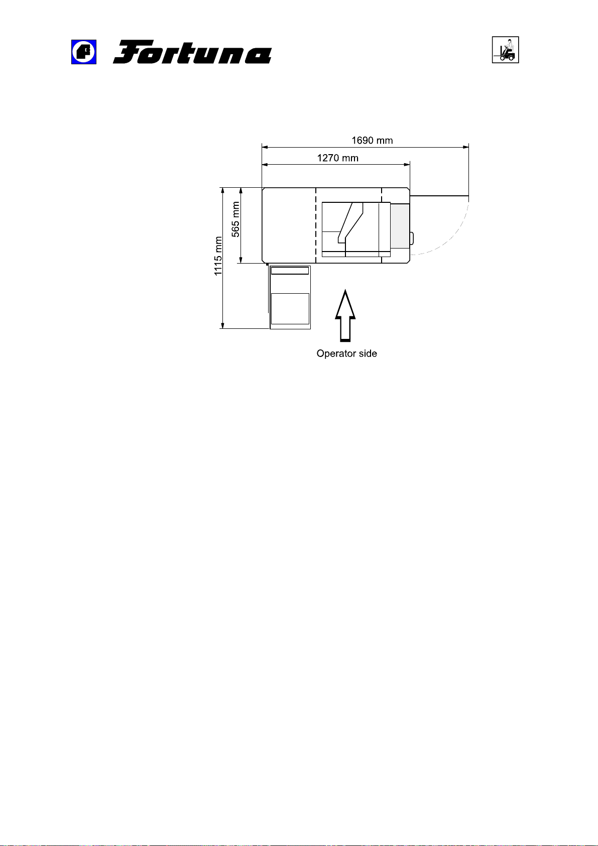
1.10.3 Installation of the machine
Figure 4: Installation plan of the machine
The floor space requirements for the operational machine can be calculated
from the above figure. The floor area of the machine should be clean and
flat. The adjustable basescrews will mount the machine to the floor.
1.10.4 Preliminary work for start-up
Cleaning the machine
The machine is provided by the supplier with a corrosion-protective coat
which must be removed prior to start-up. The following work must be
carried out:
Cleaning of all belt pulleys.
Cleaning of the guide element (presser roll/foot).
Cleaning of the bell knife.
Accessory equipment for the installation
The work lamp is fitted to the bushing socket and fastened with the cap
screw mounted on the lamp.
———————————————————————————–––––––––––––––––––––––––
Operating Manual Skiving Machine ES 50-UK-V3/24.01.2012 26 von 45
Page 27
Installing the machine
—————————————————————————————————————–———
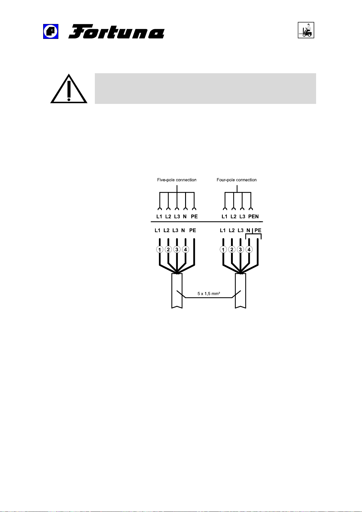
1.10.5 Electrical connection
Electrical work must only be carried out by a qualified electrician.
A complete circuit diagram is part of the technical documentation of this
machine and can be found in the switch cabinet of the machine.
Observe the safety rules of the local power station.
Before connecting the machine to the mains ensure that the voltage and
frequency correspond to the values provided on the switch cabinet.
For more information please refer to Chapter 1.1.3 Electrical data (page 9).
Figure 5: Mains connection cables of the machine
When connecting the cables, ensure that there is a right three-phase field
between the phases L1, L2 and L3.
———————————————————————————–––––––––––––––––––––––––
Operating Manual Skiving Machine ES 50-UK-V3/24.01.2012 27 von 45
Page 28

Installing the machine
—————————————————————————————————————–———
We recommend the following procedure for checking the three-phase
field:
Turn on the machine for a brief period, then immediately turn off the
machine again.
A right three-phase field exists when the bell knife turns to the rear – seen
from the operator side.
Two of the three phase connections (L1, L2, L3) must be interchanged
when the sense of rotation is not correct.
Even operating the machine with a left three-phase field for only a few
seconds may endamage various machine parts.
1.11
Start-up
1.11.1 Installation of the regulator pedal
Place the foot pedal in the floor space of the machine and screw it down on
an mounting angle. The bottom side of the pedal consists of nonskid rubber
knubs. The connector of the pedal is plugged into the socket on the
backside of the switch cabinet. The plugs with reverse battery protection is
keyed and can only be connected in one position. Please refer to Figure 9:
Details of the machine – front view (page 44).
———————————————————————————–––––––––––––––––––––––––
Operating Manual Skiving Machine ES 50-UK-V3/24.01.2012 28 von 45
Page 29
User manual
—————————————————————————————————————–———
2 User manual
The Skiving machine ES 50 must be operated from the front side by one
person. The operator must be trained and made familiar with the control
elements prior to the start-up of the machine. For this purpose, Figure 9:
Details of the machine – front view (page 44) should be folded out.
The machine must only be operated with completely closed covering.
Cover plates and machine parts must not be removed during operation.
Conditions for skiving
Sharp knife edge
Smooth, undamaged guiding edge of the presser foot
Correct distance between knife edge and presser foot
Determination of the correct distance between knife and presser foot
Normal upper leather 0,3 – 0,4 mm
Fine leather 0,2 mm
Thick and hard leather 0,5 mm
Main switch
2.1
POWER
0
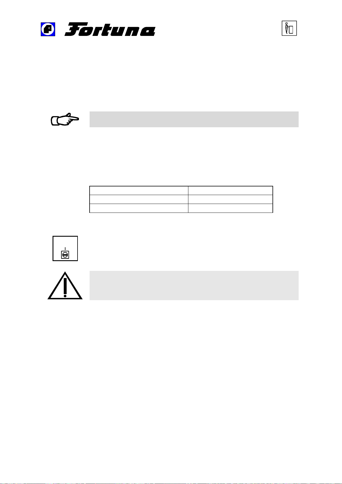
This switch (15) turns the main power supply on or off. The machine is
now ready for operation.
Note: Switching on this interrupter activates the knife, the aspiration, the
grinding device and possibly the drive as well according to the position
of the feed potentiometer.
The main switch is provided with an emergency stop function that
disconnects the machine completely from the main supply.
———————————————————————————–––––––––––––––––––––––––
Operating Manual Skiving Machine ES 50-UK-V3/24.01.2012 29 von 45
Page 30
User manual
—————————————————————————————————————–———
Explanation of the control elements
2.2
2.2.1 Adjusting screw for adjusting the skiving thickness
The desired skiving thickness of the treated material is adjusted by means
of this adjusting screw (7). The operating result depends on the material
and should be checked by means of the thickness gauge (optional).
An eccentric lever (8) that can be adjusted in two positions is placed below
the adjusting screw (7). Please refer to , Figure 9: Details of the machine –
front view (page 44).
Lever in upper position: the presser foot can be replaced.
Lever in lower position: working position = skiving of the material.
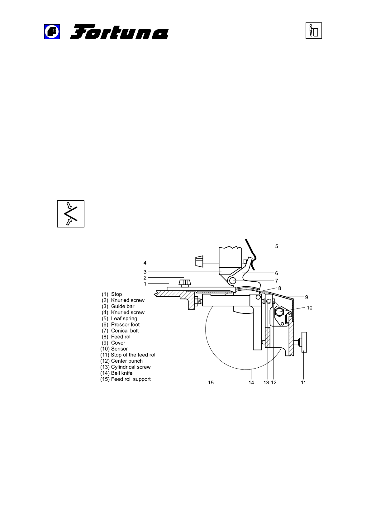
2.2.2 Knurled screw for adjusting the skiving angle
Use this knurled screw (4) to carry out the adjustment of the skiving
angle from a parallel position to its maximum width. The pressure
generated by the leaf spring (5) fixed on the front side enables the
skiving angle to be adjusted correctly and free from play.
For information on the position of the knurled screw and the leaf spring,
please refer to Figure 6: Knife guidance (page 30).
Figure 6: Knife guidance
———————————————————————————–––––––––––––––––––––––––
Operating Manual Skiving Machine ES 50-UK-V3/24.01.2012 30 von 45
Page 31
User manual
—————————————————————————————————————–———
2.2.3 Stop for adjusting the skiving width
The skiving width is adjusted by opening the knurled screw (2) and by
shifting the stop (1) in the slotted hole. Please refer to Figure 6: Knife
guidance (page 30).
2.2.4 Adjusting spindle for adjusting the grinding intensity
The grinding intensity for the sharpening of the knife is adjusted by
means of this adjusting spindle (13). Please refer to , Figure 9: Details
of the machine – front view (page 44).
We recommend to sharpen the knife lightly in regular intervals.
Adjustment process
Slowly turn the adjustment screw in counterclockwise direction. The
grinding intensity is increased.
Slowly turn the adjustment screw in clockwise direction. The grinding
intensity is reduced.
2.2.5 Adjusting screw for dressing the grinding wheel
Use this adjusting screw (3), see Figure 9: Details of the machine –
front view (page 44) to dress the grinding wheel. The grinding wheel
should be dressed about twice a day depending on the material to be
treated in order to prevent a clogging of the grinding wheel and to
sharpen it.
Dressing process
For this purpose, the adjusting screw is lightly pressed to the inside and
turned to the limit stop. Thus, the grinding wheel is dressed on its complete
width.
———————————————————————————–––––––––––––––––––––––––
Operating Manual Skiving Machine ES 50-UK-V3/24.01.2012 31 von 45
Page 32
User manual
—————————————————————————————————————–———
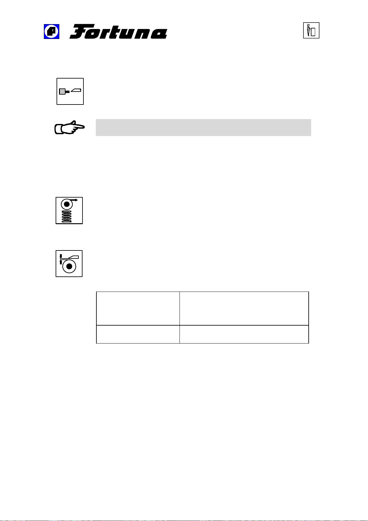
2.2.6 Opening for blunting and deburring the bell knife
Deburring the knife is absolutely mandatory to obtain a satisfactory
separation cut. This opening is required for blunting the knife and/or
for deburring its inside by means of the supplied oil stone. Please
refer to Chapter 1.1.5 Tools and accessories (page 10).
The blunting of the knife must principally be carried out for all work
that is described in this Operating Manual prior to opening the cover.
Exceptions can only be made when it is specially pointed out in this
Operating Manual.
2.2.7 Adjusting screw for adjusting the contact pressure of
the feed roll
The contact pressure of the feed roll is adjusted by means of this
adjusting screw (1). The contact pressure is increased by turning the
adjusting screw in a clockwise direction, whereas it is reduced by
turning the adjusting screw in a counterclockwise direction.
2.2.8 Adjusting screw for adjusting the feed roll distance
The distance between the feed roll and the knife edge is reduced or
increased with this adjusting screw (2).
The following reference values must be observed
Emery feed roll The emery feed roll should be adjusted in
parallel alignment with the knife. The
distance between the emery feed roll and
the knife is 0.1 mm.
Steel feed roll The distance between knife edge and
feed roll should be at least 0.2 mm.
———————————————————————————–––––––––––––––––––––––––
Operating Manual Skiving Machine ES 50-UK-V3/24.01.2012 32 von 45
Page 33
User manual
—————————————————————————————————————–———
2.2.9 Adjusting spindle for the knife infeed
By turning the adjusting spindle (12) of the knife infeed in a
counterclockwise direction the bell knife is moved closer to the
presser foot.
2.2.10 Setpoint potentiometer
Use this potentiometer (16) to adjust the area in which the feed speed
can be controlled by means of the regulator pedal. Please refer to
Figure 9: Details of the machine – front view (page 44).
The scale shows values from 1 to 10 and in the center position (set
value: 5) it is possible to adjust the rate of feed from 0 to 100 %.
In the minimum setting (value: 0) the rate of feed can be adjusted with
the regulator pedal from 0 to 50 %.
In the maximum setting (value: 10) the rate of feed can be adjusted
from 50 to 100 % by means of the regulator pedal, i. e. the feed roll
turns even if the pedal is not being actuated.
2.2.11 Regulator pedal
The regulator pedal (18) is located on the bottom below the machine.
Please refer to Figure 9: Details of the machine – front view (page 44).
The rate of feed can be regulated by means of this regulator pedal.
It is useful to preset the rate of feed at the setpoint potentiometer, please
refer to Chapter 2.2.10 Setpoint potentiometer (page 33).
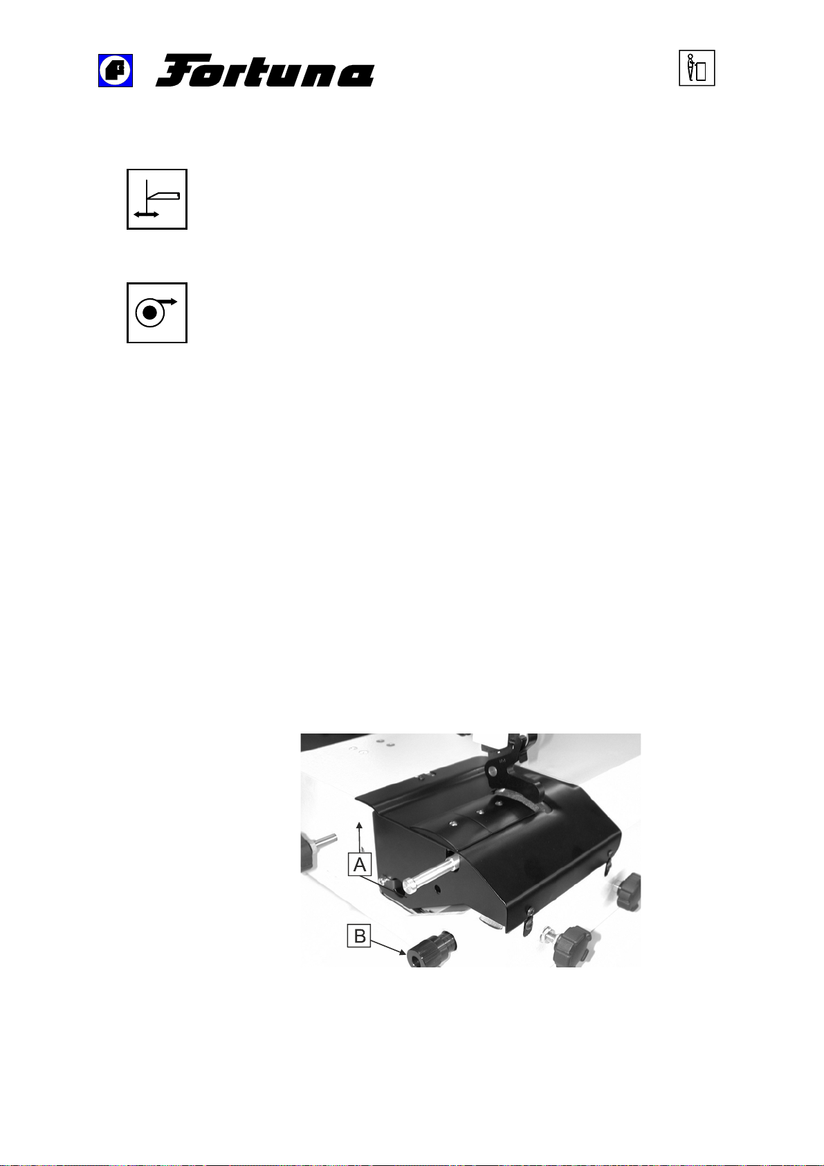
2.2.12 Handle
The handle is included in the tools.
With the handle the scraps can be removed easily and you can check with
it the feeding power.
Thus, the complete cover plate has not to be opened.
A: Lift-up to remove scraps / to check feeding power
B: See Chapter 2.2.7
Adjusting screw for adjusting the contact pressure of the feed roll
(Seite 32).
———————————————————————————–––––––––––––––––––––––––
Operating Manual Skiving Machine ES 50-UK-V3/24.01.2012 33 von 45
Page 34
User manual
—————————————————————————————————————–———
Adjustment of the knife position indicator
2.3
General information
There are two ways of indicating the knife position:
Analog bar graph display
Digital 4 ½-place seven-segment display
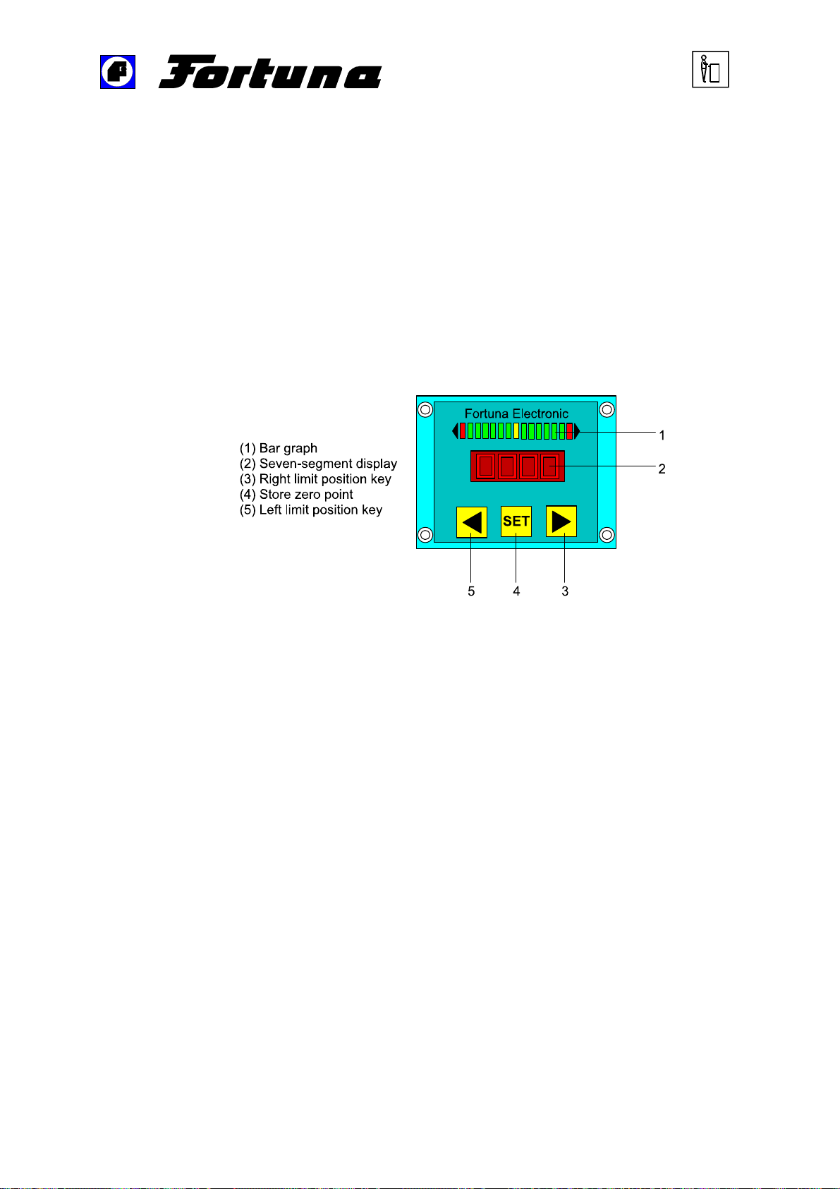
Bar graph
The analog bar graph display is performed by LED
Yellow LED in the middle Knife position OK
Red LED on the left Limit left knife position
Red LED on the right Limit right knife position
Green LEDs Possible intermediate postitions
Seven-segment display
The seven-segment display should only be switched on to adjust the
analog sensor. It shows the inital tension of the analog sensor in 1/100 V.
To deactivate the seven-segment display, press simultaneously the keys
◄ and ►.
———————————————————————————–––––––––––––––––––––––––
Operating Manual Skiving Machine ES 50-UK-V3/24.01.2012 34 von 45
Page 35
User manual
—————————————————————————————————————–———
Programming
Adjust the distance between knife and pressure foot mechanically to 0.4
mm.
Position the analog sensor mechanically and fix it until the seven-segment
display shows 05.00.
Press the SET key (4) to store the zero point.
Move the knife mechanically towards the left position (the distance between
knife and pressure foot is 0.2 mm).
Press the left key ◄ (5) to store this position.
Move the knife mechanically towards the right position (the distance
between knife and pressure foot is 0.6 mm).
Press the right key ► (3) to store this position.
Figure 7: Knife position indicator
———————————————————————————–––––––––––––––––––––––––
Operating Manual Skiving Machine ES 50-UK-V3/24.01.2012 35 von 45
Page 36

User manual
—————————————————————————————————————–———
Adjustment of the feed regulator
2.4
The regulator is adjusted by means of four potentiometers which are
mounted on the regulator board.
Inscription Function
N
Adjustment of the maximum speed
max
V Torque adjustment
Strom (Current) Rated motor current adjustment
0-Punkt (Zero point) Dwell speed adjustment
Adjustment of the potentiometers
Inscription Setting
Set the external potentiometer at the center
position (value: 5).
Press the regulator pedal until ist stop.
N
max
Use a speed counter to adjust the maximum
speed by means of the potentiometer.
Turning to the right increases the speed.
Turning to the right reduces the speed.
Adjust a low speed by means of the
regulator pedal or an external potentiometer.
Reduce the feed motor speed applying a low
braking force.
The optimum adjustment has been reached
V
Current
when the motor neither increases nor
decreases under load.
Turning to the right increases the
amplification.
Turning to the left decreases the
amplification.
Adjust the rated current of the motor used. With
a low speed it must only be possible to stop the
motor applying an increased force and at its
maximum speed the motor must not pulse.
Turning to the right increases the motor current.
Turning to the left decreases the motor current.
———————————————————————————–––––––––––––––––––––––––
Operating Manual Skiving Machine ES 50-UK-V3/24.01.2012 36 von 45
Page 37

User manual
—————————————————————————————————————–———
Do not push the regulator pedal.
Set the external potentiometer at the center
position (value 5).
Zero point
Jumper
The jumper on the regulator board serves to bridge the external regulator
pedal.
Jumper plugged in - regulator pedal is bridged.
Jumper removed - regulator pedal connected.
Turn the zero point potentiometer until the
feed motor just starts turning.
Now turn back until the feed motor stops.
Turning to the right increases the speed.
Turning to the left decreases the speed.
Figure 8: Regulator
———————————————————————————–––––––––––––––––––––––––
Operating Manual Skiving Machine ES 50-UK-V3/24.01.2012 37 von 45
Page 38

Inspection and maintenance work
—————————————————————————————————————–———
Cleaning
2.5
2.5.1 Daily cleaning
The following cleaning must be carried out daily, please refer to Chapter
2.6.2 Cleaning and maintenance schedule (page 43).
Switching off the machine
Emptying the scrap material bin
Open the door of the scrap material bin.
The scrap material bin which is located on the left side of the work table
must be removed.
Extract the filter cartridge, clean it and make sure that it fits correctly.
The scrap material bin must be emptied.
Clean the rubber gasket of the filter cartridge and control if it is damaged.
If the rubber gasket is damaged it must be replaced in order to guarantee
optimal scrap suction.
Insert the filter cartridge.
Replace the scrap material bin.
Close the door of the scrap material bin.
———————————————————————————–––––––––––––––––––––––––
Operating Manual Skiving Machine ES 50-UK-V3/24.01.2012 38 von 45
Page 39

Inspection and maintenance work
—————————————————————————————————————–———
2.5.2 Weekly cleaning
The following cleaning must be carried out weekly, please refer to Chapter
2.6.2 Cleaning and maintenance schedule (page 43).
Stopping the machine
Cleaning the inside space of the machine
Open the upper part of the machine by removing the countersunk screw in
the upper part of the machine with a hexagonal socket-head wrench. Then
the upper part of the machine can be tilted to the rear. The safety loop
snaps in automatically.
Thoroughly clean the inside space of the machine with a vacuum cleaner.
Clean the grid at the suction pipe "Scrap suction".
Do not use compressed air in order to avoid the blowing of dust into
the inside space of the machine.
Lubricating the rotary segment
Lubricate the rotary segment through the upper borehole with some drops
of sewing-machine oil.
———————————————————————————–––––––––––––––––––––––––
Operating Manual Skiving Machine ES 50-UK-V3/24.01.2012 39 von 45
Page 40

Inspection and maintenance work
—————————————————————————————————————–———
Maintenance work
2.6
In order to guarantee optimum functioning of the machine, the following
maintenance work must be carried out within the indicated intervals. For
more information, please refer to Chapter 2.6.2 Cleaning and maintenance
schedule (page 43). The mechanical maintenance work must only be
carried out by skilled personnel.
All ball bearings of the machine are covered and therefore
maintenancefree.
Weekly work
The following maintenance work must be carried out weekly:
Clean and lubricate the knife infeed.
Clean and lubricate the grinding infeed.
Lubricate the flat bearing of the guide head.
Clean the grinding area.
Check the suction pipe and if it is dirty, clean it.
Monthly work
Clean and lubricate the point suspension of the feed shaft bearing arm.
Check the belts and the belt tensions and, if neccessary, replace them by
new ones.
———————————————————————————–––––––––––––––––––––––––
Operating Manual Skiving Machine ES 50-UK-V3/24.01.2012 40 von 45
Page 41
Troubleshooting
—————————————————————————————————————–———
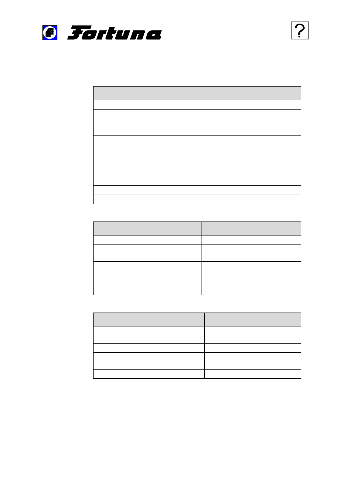
2.6.1 Troubleshooting
2.6.1.1 Bad skiving results
Cause Elimination
Bell knife is blunt. Regrind bell knife.
Knife has a burr inside. Remove burr with emery feed
roll or oil stone.
Increased inside knife chamfer. Regrind bell knife.
Grinding wheel is blunt and/or
clogged.
Adjustment of the bell knife is
incorrect.
Presser foot is worn. Replace presser foot by a new
Stop is worn. Replace stop by a new one.
Play in flat bearing of guide head. Readjust flat bearing.
Dress grinding wheel.
Readjust distance to presser
foot.
one.
2.6.1.2 Insufficient feeding
Cause Elimination
Feeding power too low. Increase feeding power.
Feed roll is worn. Replace feed roll with a new
Feed roll is smudged. Remove the abraded leather
Bell knife is blunt. Regrind bell knife.
2.6.1.3 Bevels are too thick
Cause Elimination
Position of presser foot too high. Change adjustment of the
Position of stop is not correct. Readjust position of stop.
One side of presser foot is worn. Replace presser foot by a new
Feed roll is damaged. Replace feed roll by a new one.
one.
particles from the feed roll with a
steel brush.
presser foot.
one.
———————————————————————————–––––––––––––––––––––––––
Operating Manual Skiving Machine ES 50-UK-V3/24.01.2012 41 von 45
Page 42

Troubleshooting
—————————————————————————————————————–———
2.6.1.4 Insufficient scrap removal
Cause Elimination
Scrap ejector is not adjusted
correctly.
Scrap material bin is not inserted
correctly.
Scrap material bin is full. Empty scrap material bin.
Filter is clogged. Clean filter.
Suction pipe is clogged. Clean suction pipe.
2.6.1.5 Noisy operation
Cause Elimination
Nylon sliding sleeve of knife drive is
worn (chattering noise).
2.6.1.6 Electrical troubles
Description of the Trouble Elimination
Work lamp does not light.
Correctly adjust scrap ejector.
Check scrap material bin.
Remove sliding sleeve and
replace it with a new one.
Check fuse and if
necessary, replace it by a
new one.
Halogen bulb lamp
defective, replace it by a
new one.
———————————————————————————–––––––––––––––––––––––––
Operating Manual Skiving Machine ES 50-UK-V3/24.01.2012 42 von 45
Page 43
Cleaning and maintenance schedule
—————————————————————————————————————–———
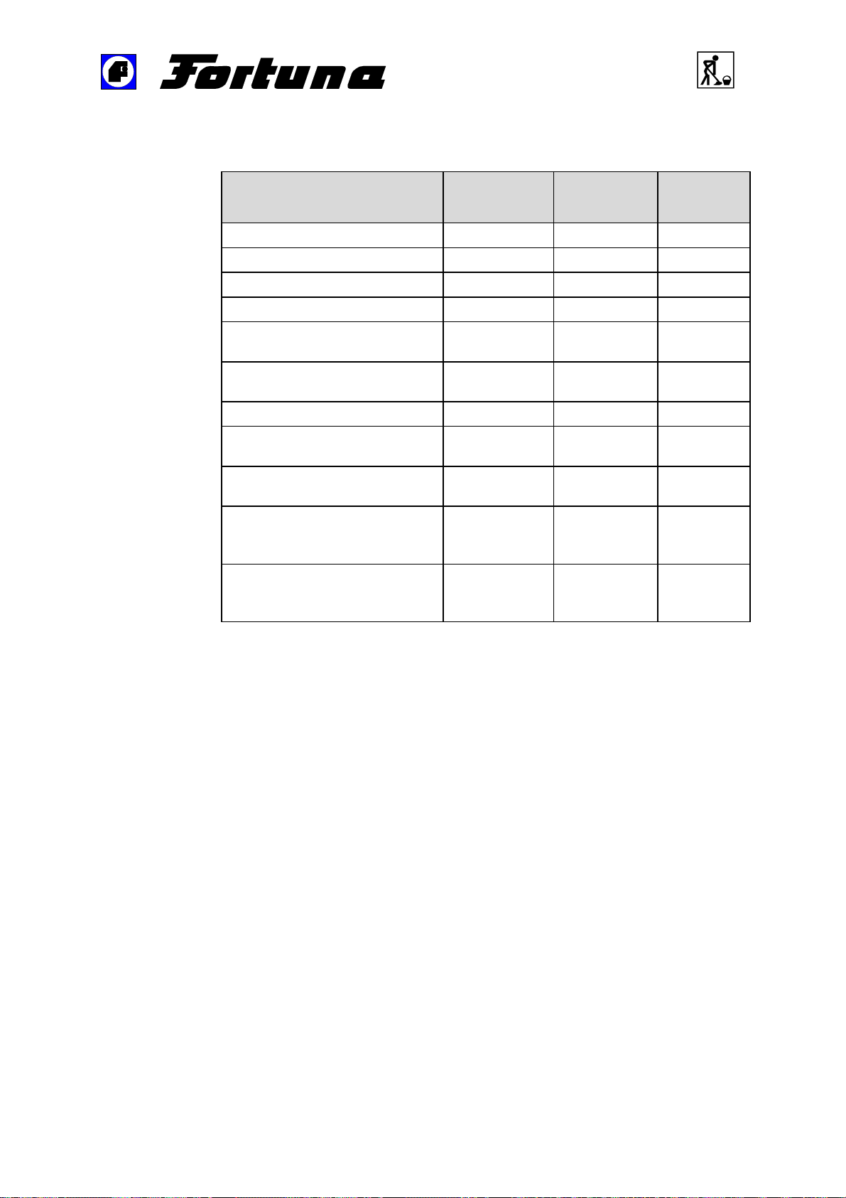
2.6.2 Cleaning and maintenance schedule
Cleaning and maintenance
work to be carried out
Clean machine.
Readjust scrap ejector.
Clean filter cloth.
Empty scrap material bin.
Clean and lubricate knife
infeed.
Lubricate flat bearing of guide
head.
Clean grinding zone.
Check suction pipe and clean
it, if it is contaminated.
Clean the grid at the suction
pipe "Scrap suction".
Clean and lubricate point
suspension of the feed shaft
bearing arm.
Check belts and belt tensions
and if they are worn, replace
them with new ones.
Daily Weekly Monthly
X
X
X
X
X
X
X
X
X
X
X
———————————————————————————–––––––––––––––––––––––––
Operating Manual Skiving Machine ES 50-UK-V3/24.01.2012 43 von 45
Page 44
Views and detailed drawings
—————————————————————————————————————–———
Views and detailed drawings
2.7
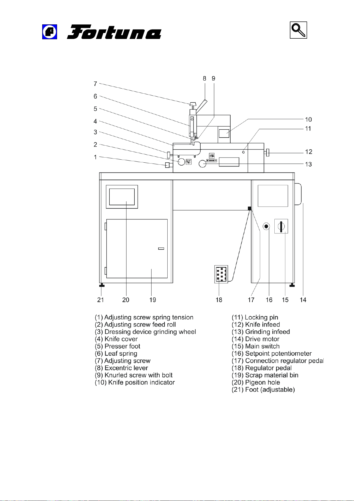
Figure 9: Details of the machine – front view
———————————————————————————–––––––––––––––––––––––––
Operating Manual Skiving Machine ES 50-UK-V3/24.01.2012 44 von 45
Page 45
Views and detailed drawings
—————————————————————————————————————–———
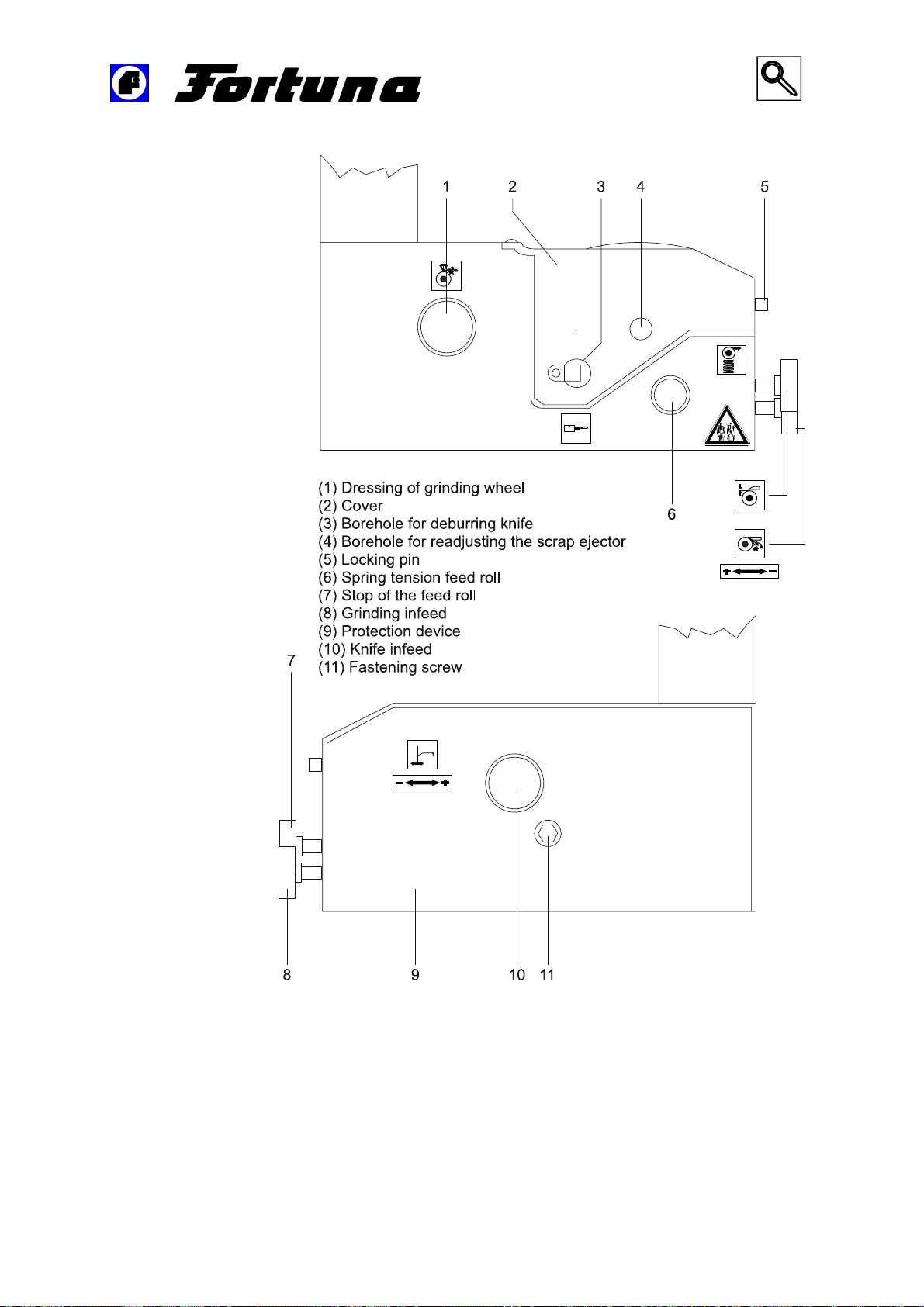
Figure 10: Details of the machine – lateral view
———————————————————————————–––––––––––––––––––––––––
Operating Manual Skiving Machine ES 50-UK-V3/24.01.2012 45 von 45
 Loading...