

Page 1
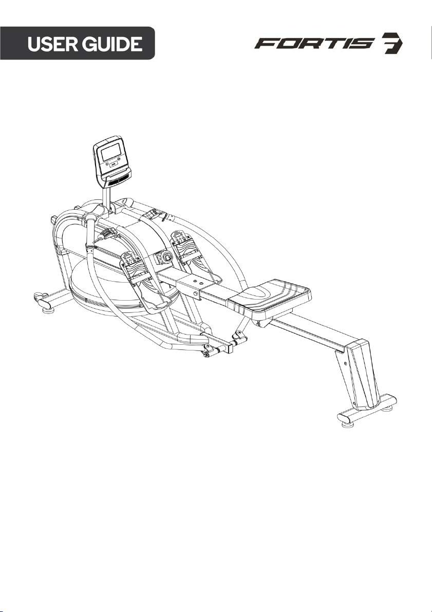
WATER & MAGNETIC HYBRID
FULL MOTION ROWING MACHINE
(MR-600)
FSWMHMR600A
Page 2

Page 3

Read all of the instructions in this guide before using this product. Retain this guide for
future reference. Do not skip, substitute or modify any steps or procedures in this guide, as
doing so could result in personal injury or product damage.
• Before starting any exercise program, consult your physician to determine if you have
any medical or physical conditions that could put your health and safety at risk or
prevent you from using the equipment properly. Your physician’s advice is essential if
you are taking any medication that may affect your heart rate, blood pressure or
cholesterol level.
• Incorrect or excessive exercise can damage your health. Stop exercising if you
experience any of the following symptoms: pain, tightness in your chest, irregular
heartbeat, shortness of breath, light headedness, dizziness or feelings of nausea. If you
experience any of these conditions, you should consult your physician before continuing
with your exercise program.
• This equipment is intended for adult use only. Keep children and pets away from the
machine. DO NOT leave children unattended in the same room with the equipment.
• This appliance is designed for consumer use. Follow directions and use only as
described.
• Once fully assembled, inspect to ensure all hardware parts such as bolts, nuts and
washers are positioned correctly and tightly secured.
• Always inspect the safety chain guard that protects the moving parts of the bike to be
in safe and good order.
• Always inspect the seat, seat slider and grips to make sure they are in safe and stable
position before using the rower.
• It is recommended to lubricate all moving parts on a monthly basis.
• Do not wear loose clothing while rowing.
• Dry after each use to remove moisture. Wipe regularly with a mild, non-abrasive cleaner
and water solution. To avoid damaging the finish, never use a petroleum-based
solvent.
• Use the equipment on a solid, flat level surface with a protective cover for your floor or
carpet. To ensure safety, the equipment should have at least 2 feet (approximately 60
cm) of free space on each side.
• Prior to assembly, ensure you have all the components and tools listed. Some
components are pre-assembled to help with the assembly process.
• Always use the equipment as intended. If you find any defective components while
assembling or checking the equipment, or if you hear any unusual noises coming from
the equipment during exercise, cease use immediately and contact help.kogan.com for
assistance. Do not use until resolved.
• Do not place fingers or any other objects into moving parts of the exercise equipment.
• Do not exceed the maximum user weight of 120KG.
Page 4

• Be careful when lifting and moving the equipment. Always use proper lifting technique
and seek assistance if necessary.
• Your equipment is intended for use in cool, dry conditions. You should avoid storage in
extreme cold, hot or damp areas as this may lead to corrosion and other related
problems.
• Operating temperature: 0 - 40 °C
• Storage temperature: -10 - 60°C
• This appliance contains no user-serviceable parts. If it suffers any failure or damage,
cease use immediately and contact help.kogan.com
• This equipment is designed and intended for indoor use only.
Page 5
Page 6
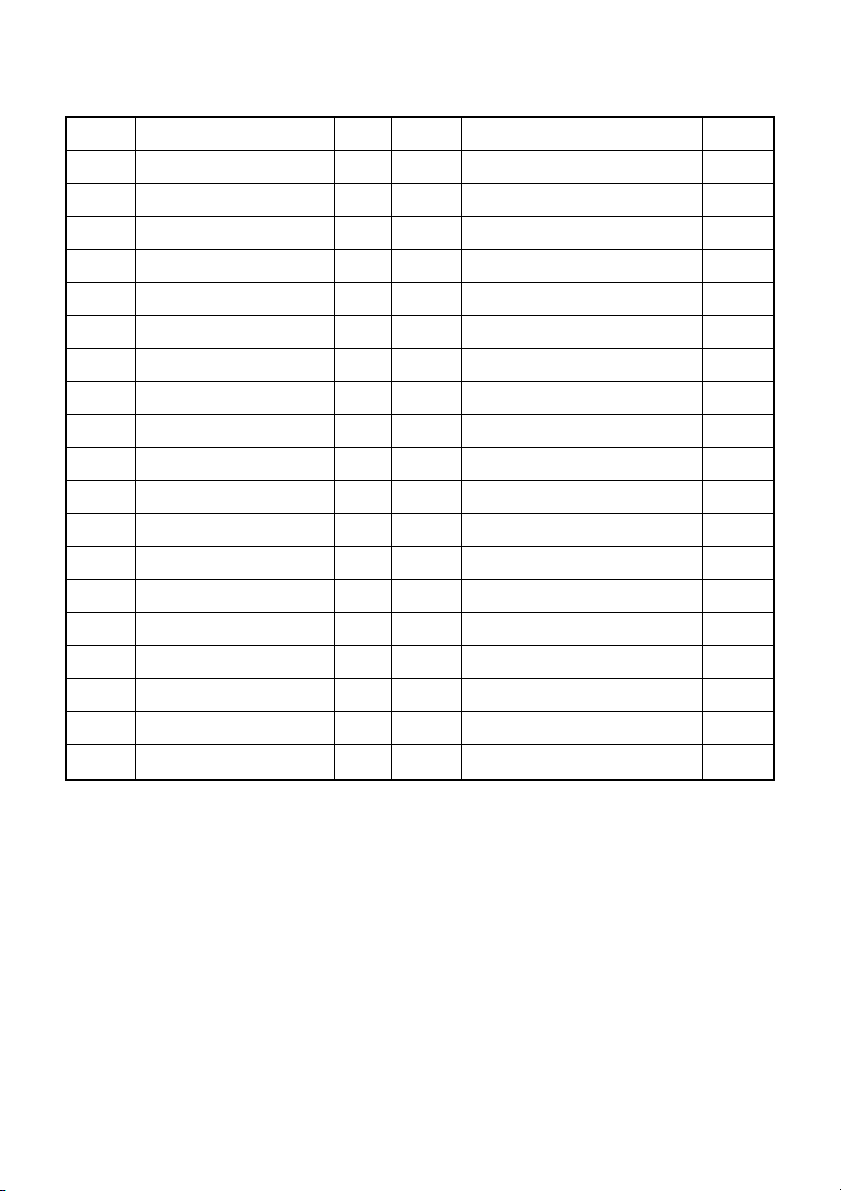
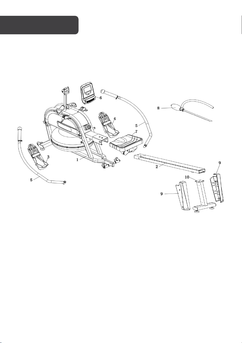
Part
Description
Qty.
Part
Description
Qty.
1
Main frame
1
18
Bolt M10 x 60 x 47 x 13 x S6
2
2
Rail 1 19
Cover 314 x 71 x 63.5
1
3
Left Pedal
1
20
Screw ST4.2 x 19 x Ф11
4
4
Right Pedal
1
21
Cushion 60 x 40 x 15.2
2
5
Rowing Rod
2
22
Bolt M8 x 20 x S6
6
6
Console
1
23
Washer d8
4
7
Seat 1 24
Washer d8 x Φ16 x 1.5
6
8
Manual water pump
1
25
Screw M5 x 10 x Φ10
4
9
Cover 1 26
Bolt Φ12 x 121 x M10 x 12
1
10
Rear stabilizer
1
27
Washer d10 x Φ20 x 2
1
11
Front Post
1
28
Nut M10 x H9.5 x S17
1
12
Bolt M12 x 20 x S8
4
29
Screw M5
4
13
Washer d12
4
30
Console Seat
1
14
Washer d12 x Φ24 x 2
4
31
Washer d10 x Φ20 x 2
2
15
Buckle Φ5 x 50
3
32
Nut M10 x H9.5 x S17
2
16
Buckle
2
33
Handlebar
2
17
Shaft Sleeve
2 C Spanner S13-14-15
1
A
Spanner S8
1 D Spanner S17-19
2
B
Spanner S6
1 E Water Purification Sheet
5
Page 7
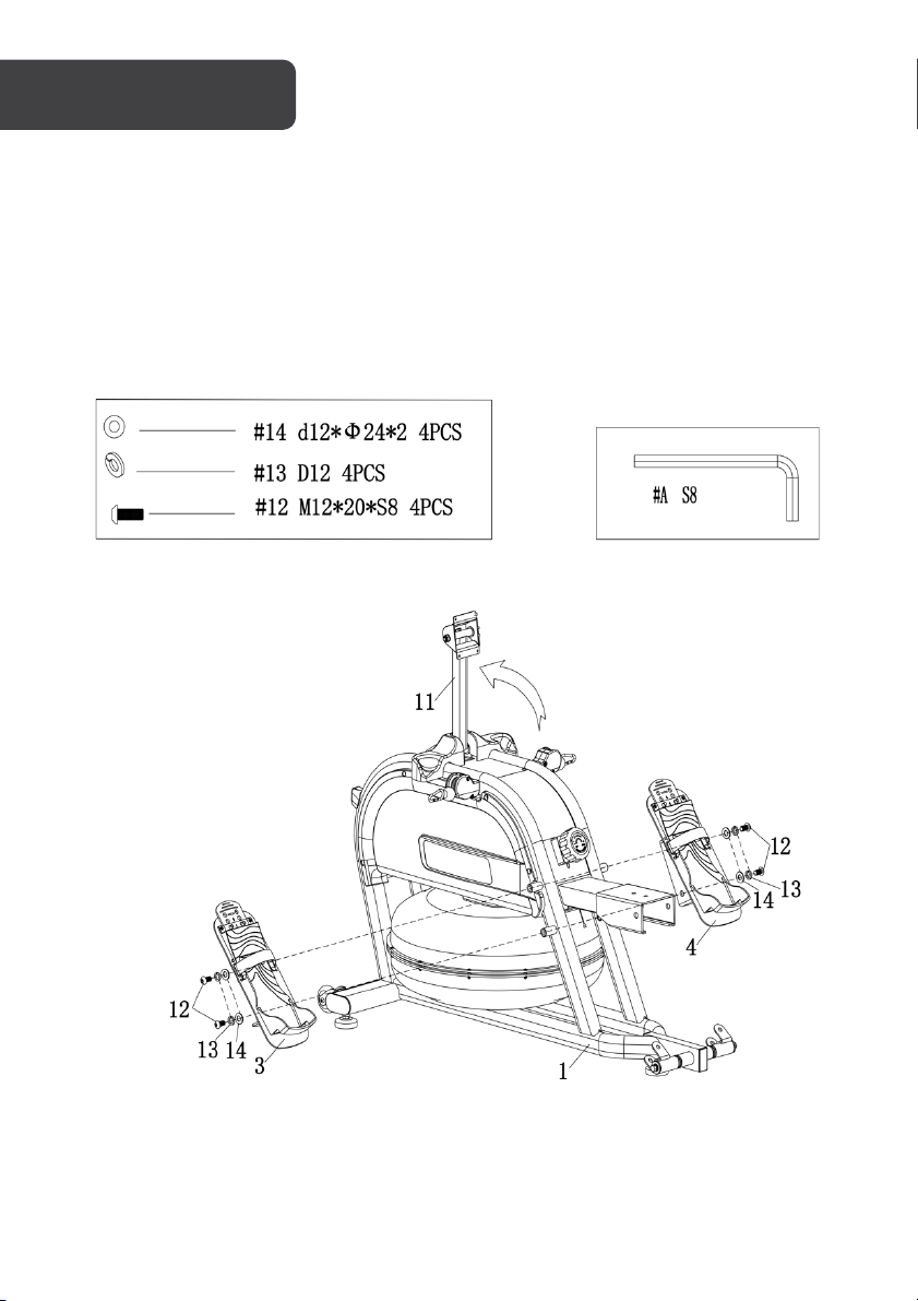
Step 1:
Lift up the front post (
12
Ta k e x2 bolt (
the left pedal (
Ta k e x2 bolt (
the right pedal (
), x2 washer (13) and x2 washers (14) through the left pedal (3). Then secure
3
) to the corresponding hole of main frame (1) using the spanner (A).
12
), x2 washer (13) and x2 washers (14) through the right pedal (4). Then secure
4
) to the corresponding hole of main frame (1) using the spanner (A).
11
) in the main frame (1).
Page 8
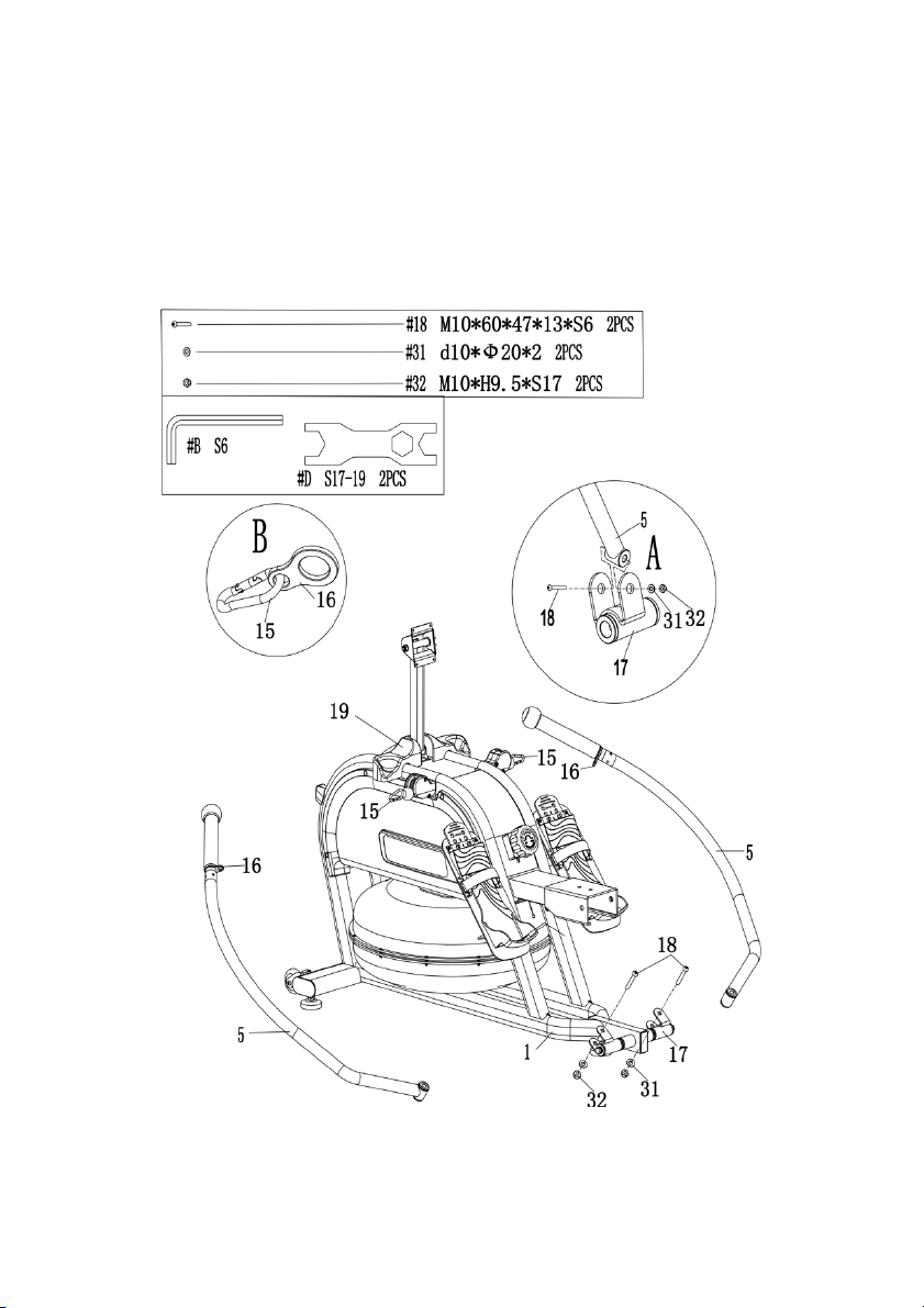
Step 2:
5
Attach the rowing rod (
5
rowing rod (
) and shaft sleeve (17). Then attach washer (31) and nut (32), secure with
) to the shaft sleeve (17), take the bolt (18) through the hole matching
spanner (A) and spanner (D).
The above assembly method is the same for left and right.
15
Connect the buckle (
5
) on the cover (19), the ball head of rowing rod (5) fall into the hollow of the cover (19).
rod (
) with buckle (16) for both the left and right separately. Put the rowing
Page 9
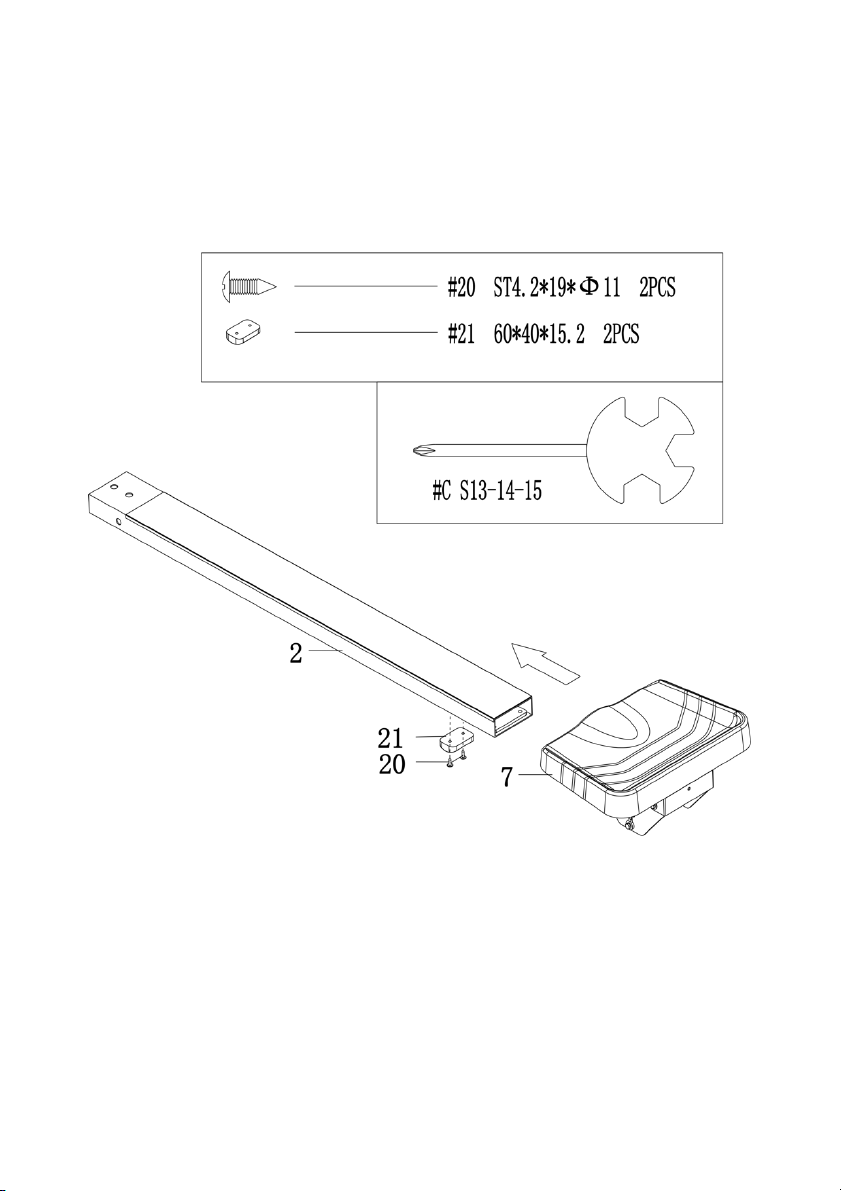
Step 3:
Remove the pre-installed cushion (
7
Slide the seat (
Secure the cushion (
) into the rail (2).
21
) and x2 screws (20) to the rail (2) using spanner (C).
21
) and x2 screws (20) from the rail (2) using spanner (C).
Page 10
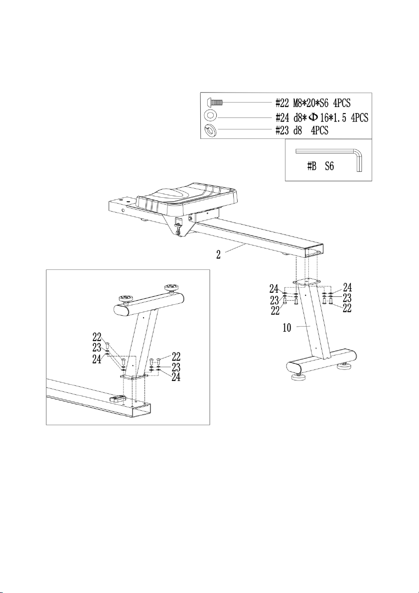
Step 4:
10
Attach the rear stabiliser (
24
). Then fasten it using spanner (B).
(
) to the rail (2) with x4 bolts (22), x4 washers (23) and x4 washers
Page 11
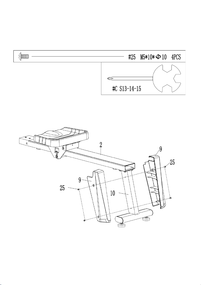
Step 5:
9
Fas ten the L/R cover (
) to the rail (2) and rear stabiliser (10) separately. Put the x4 screw (25)
through the hole of L/R cover (
9
). Then fasten it to rear stabiliser (10) using spanner (C).
Page 12
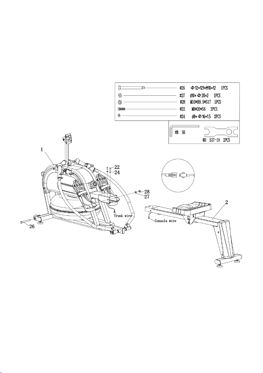
Step 6:
Figure A
Connect trunk wire and sensor wire, as shown (Figure A).
2
Insert the rail (
) to the main frame (1). Put the bolt (26) through the hole of main frame (1),
then fasten with nut (28) and washer (27) to the main frame (1) by spanner (D).
22
Put x2 bolt (
) and x2 washers (24) through the hole, then fasten the rail (2) to the main
frame (1) using spanner (B).
Page 13
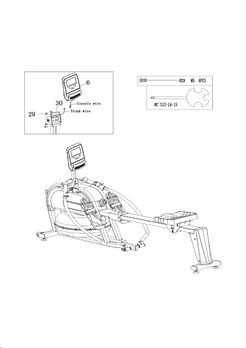
Step 7:
29
Ta k e o u t t h e x4 screw (
) from the back of console (6) by spanner (C).
Connect trunk wire with the wire of console (
(30) with x4 screws (29) by spanner (C).
The installation is completed.
6
), then secure console (6) into console Seat
Page 14
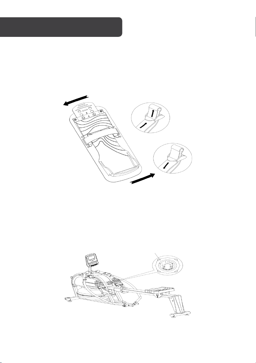
Figure A
Figure B
Loosen
Tighten
Te n s i o n C o n t r o l k n o b
Pedal strap adjustment
The Pedal Strap is adjustable and can be adjusted to fit the user’s foot size. Directions on
how to loosen and tighten the straps are shown (Figures A & B).
Te n s i o n a d j u s t m e n t
Rotate the Tension Knob clockwise to increase the level of resistance. Rotate the Tension
Knob counter-clockwise to decrease the level of resistance.
Te n s i o n l e v e l s a r e s e t a t L e v e l 1 b e i n g t h e l o w e s t a n d L e v e l 8 being the highest.
Page 15
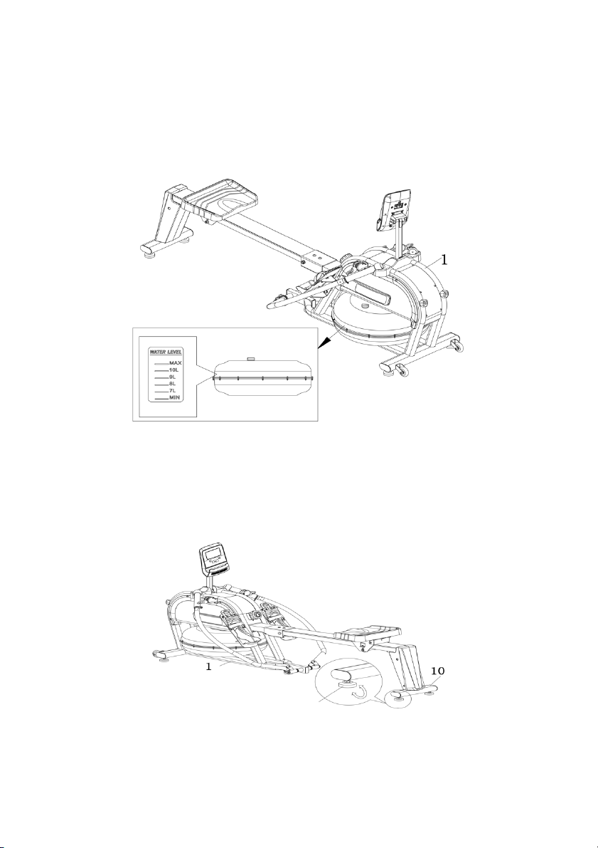
Foo t Pad
Wat er resistance
Water resistance is set between 1 to 6 levels, which is indicated by the water level sticker on
the water tank. The resistance depends on how much water is in the tank. Level 1 being the
lowest and Level 6 being the highest.
Raising the water level will increase the resistance. Lower the water level will decrease the
resistance.
Foo t pa d ad ju st men t
10
Rotate the foot pad of the rear stabilizer (
) and main frame (1) to adjust the machine’s level
and height.
Page 16
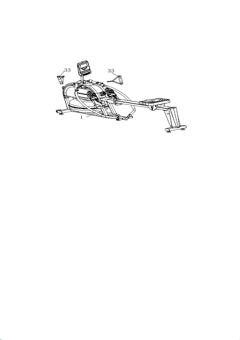
Handlebar function
2
Place the rowing rods (
Attach the two handlebars (
) in the holes on the console holder.
33
) to the hooks whenever you want to do anaerobic exercise.
Page 17

Fun cti on :
Key
MODE: Press this button to change the display or to choose a program.
SET: In the setting mode, press this button to increase the setting value for TIME, COUNT
and CAL.
Reset:
1. In setting mode, press this button to reset the value for TIME, COUNT and CAL.
2. In monitor mode, hold this button for 3 seconds to reset all values to zero.
Fun ct ion
• SCAN: Press MODE until “SCAN” appears, the computer will rotate through all the
four functions: Time, Count, Cal, Total Count. Each display will be held for 6
seconds.
• COUNT (CNT): Displays an instant count with a range from 0 ~ 9999 COUNT. The
count value can be set in advance, when it approaches the preset count, the
computer will beep for 10 seconds.
• TIME: Counts the total time from exercise start to the end with a range from 0:00 ~
99:59 minutes. Exercise time can be set in advance, when it approaches the preset
time, the computer will beep for 10 seconds. The maximum preset time is 99
minutes.
• CALORIES (CAL): Counts the total calories burned from exercise start to the end
with a range from 0.0 ~ 9999 calories. The calorie value can be set in advance,
when it approaches the preset calorie, the computer will beep for 10 seconds.
• TOTAL COUNT (TOTAL): Displays the total count from the first use. The range is
from 0 ~ 9999 COUNT.
• AUTO ON/OFF & AUTO START/STOP: When there is no signal of exercise or
operation for 4 minutes, the power will turn off automatically. Once motion begins,
the computer will turn on automatically.
Operation:
• SET: Press MODE to choose the display window that needs to be pre-set. Press
SET to increase the value to reach your desired time, calorie or count. Hold SET to
increase the value. Press RESET to reset values.
• BATTERY: When the display screen light begins to fade, remove the battery and
replace with a “AAA” battery.
Page 18
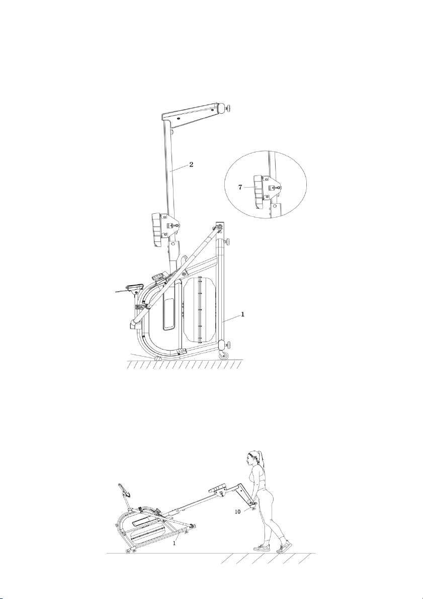
Foo t Pad
Fol di ng t he R owe r
When not in use, the rower can be folded to save space. Fold the rail (
1
of main frame (
The seat (
) touch the ground.
7
) will slide down when the rail (2) is folded. Ensure care is taken.
2
) up until the foot pad
Moving the Rower
To m o v e t h e r o w e r , l i f t u p R e a r S t a b i l i s e r (
10
) until the Transportation Wheels on main frame
(1) touch the ground. Once the Transportation Wheels are on the ground, you can transport
the rower to the desired location with ease.
Page 19
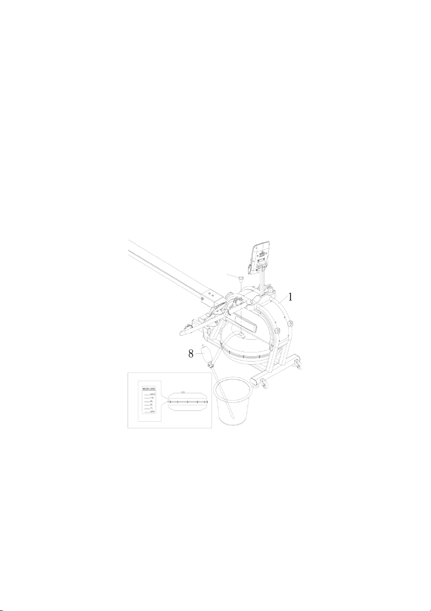
Wat er Tan k
Water tank
cover
Figure A
Adding Water:
1
1. Remove the tank cover mounted on the mainframe (
2. Fill water as shown (Figure A). Insert the Manual water pump (
the other end into the tank of the main frame (
).
8
1
). Squeeze the head of Manual
) into the water and
water pump (8), so water can be added to the water tank according to the water
level marked on water tank.
Note: Do not exceed the max water level; exceeding will damage the machine and
void the warranty.
3. Put in a Water purification sheet and replace the cover back.
Removing Water:
1. Pump water as shown (Figure A). Place a bucket next to the machine and use the
8
Manual water pump (
) to pump water from the tank into the bucket.
2. Place the cover back to the water tank and dry any water around the machine.
Attention:
• Add clear water into water tank, then put into a Water purification sheet.
Note: Do not use a damaged water purification sheets or bleach, it will damage
the machine and void the warranty.
• Add water purification sheets every 6 months or as required. If the water is very
muddy, please replace the water in the water tank.
• The water replaced in the water tank is not suitable for recycling use, please treat
as sewage.
• If the machine is not used for an extended period, please empty the water in the
water tank and fold the machine.
Page 20

Need more information?
We hope that this user guide has given you
the assistance needed for a simple set-up.
For th e most up -to-date guide for your product,
as well as any additional assistance you may require,
head online to help.kogan.com
 Loading...