

Page 1
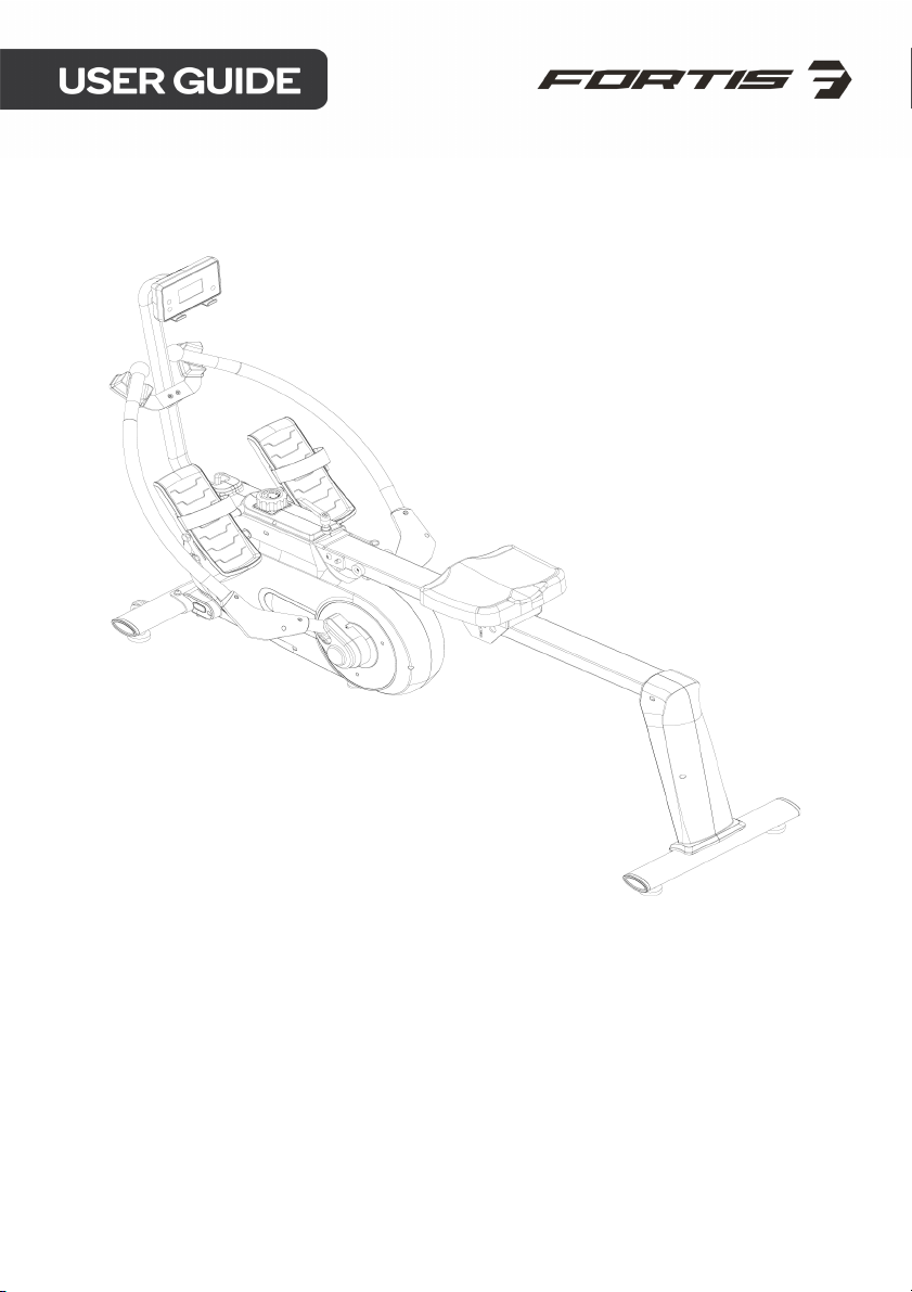
MAGNETIC FLYWHEEL FULL
MOTION ROWING MACHINE
(MR-400)
FSMFWMR400A
Page 2

Page 3

Read all of the instructions in this guide before using this product. Retain this guide for
future reference. Do not skip, substitute or modify any steps or procedures in this guide, as
doing so could result in personal injury or product damage.
• Before starting any exercise program, consult your physician to determine if you have
any medical or physical conditions that could put your health and safety at risk or
prevent you from using the equipment properly. Your physician’s advice is essential if
you are taking any medication that may affect your heart rate, blood pressure or
cholesterol level.
• Incorrect or excessive exercise can damage your health. Stop exercising if you
experience any of the following symptoms: pain, tightness in your chest, irregular
heartbeat, shortness of breath, light headedness, dizziness or feelings of nausea. If you
experience any of these conditions, you should consult your physician before continuing
with your exercise program.
• This equipment is intended for adult use only. Keep children and pets away from the
machine. DO NOT leave children unattended in the same room with the equipment.
• This appliance is designed for consumer use. Follow directions and use only as
described.
• Once fully assembled, inspect to ensure all hardware parts such as bolts, nuts and
washers are positioned correctly and tightly secured.
• Always inspect the safety chain guard that protects the moving parts of the bike to be
in safe and good order.
• Always inspect the seat, seat slider and grips to make sure they are in safe and stable
position before using the rower.
• It is recommended to lubricate all moving parts on a monthly basis.
• Do not wear loose clothing while rowing.
• Dry after each use to remove moisture. Wipe regularly with a mild, non-abrasive cleaner
and water solution. To avoid damaging the finish, never use a petroleum-based
solvent.
• Use the equipment on a solid, flat level surface with a protective cover for your floor or
carpet. To ensure safety, the equipment should have at least 2 feet (approximately 60
cm) of free space on each side.
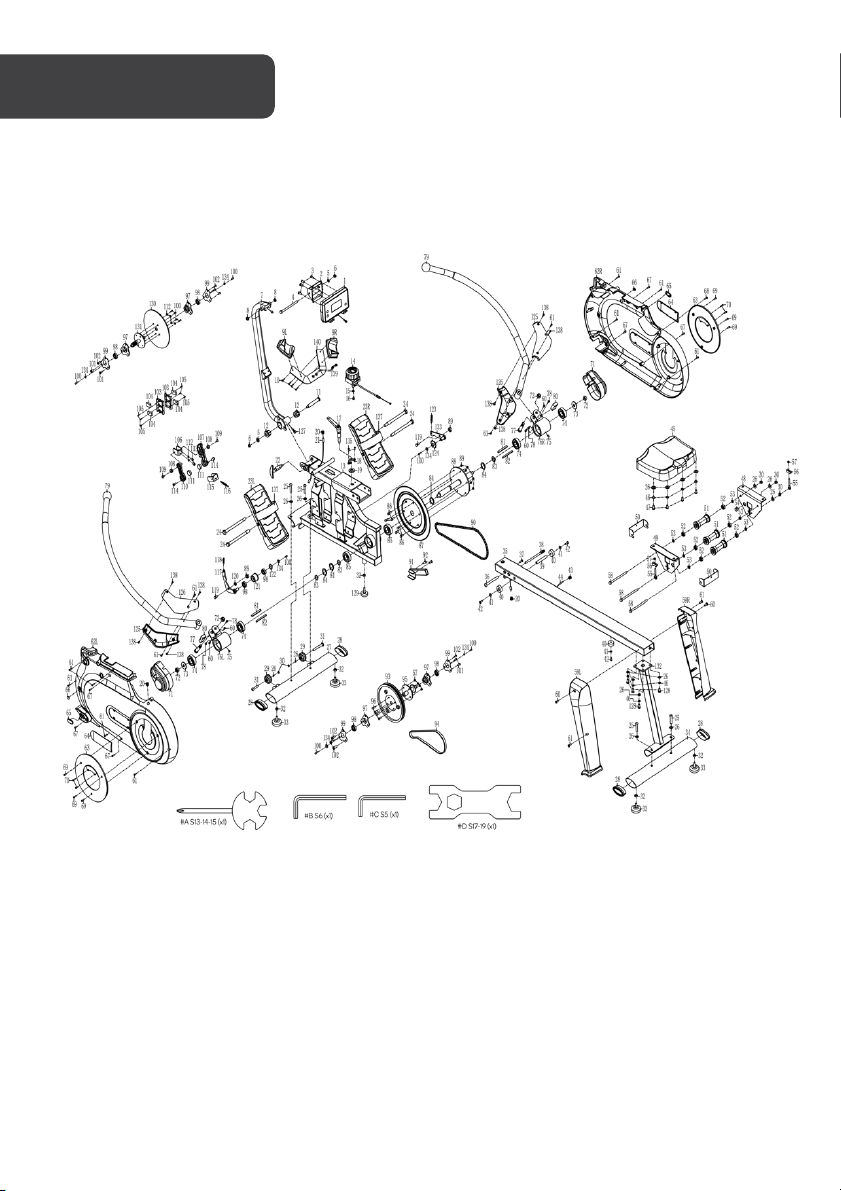
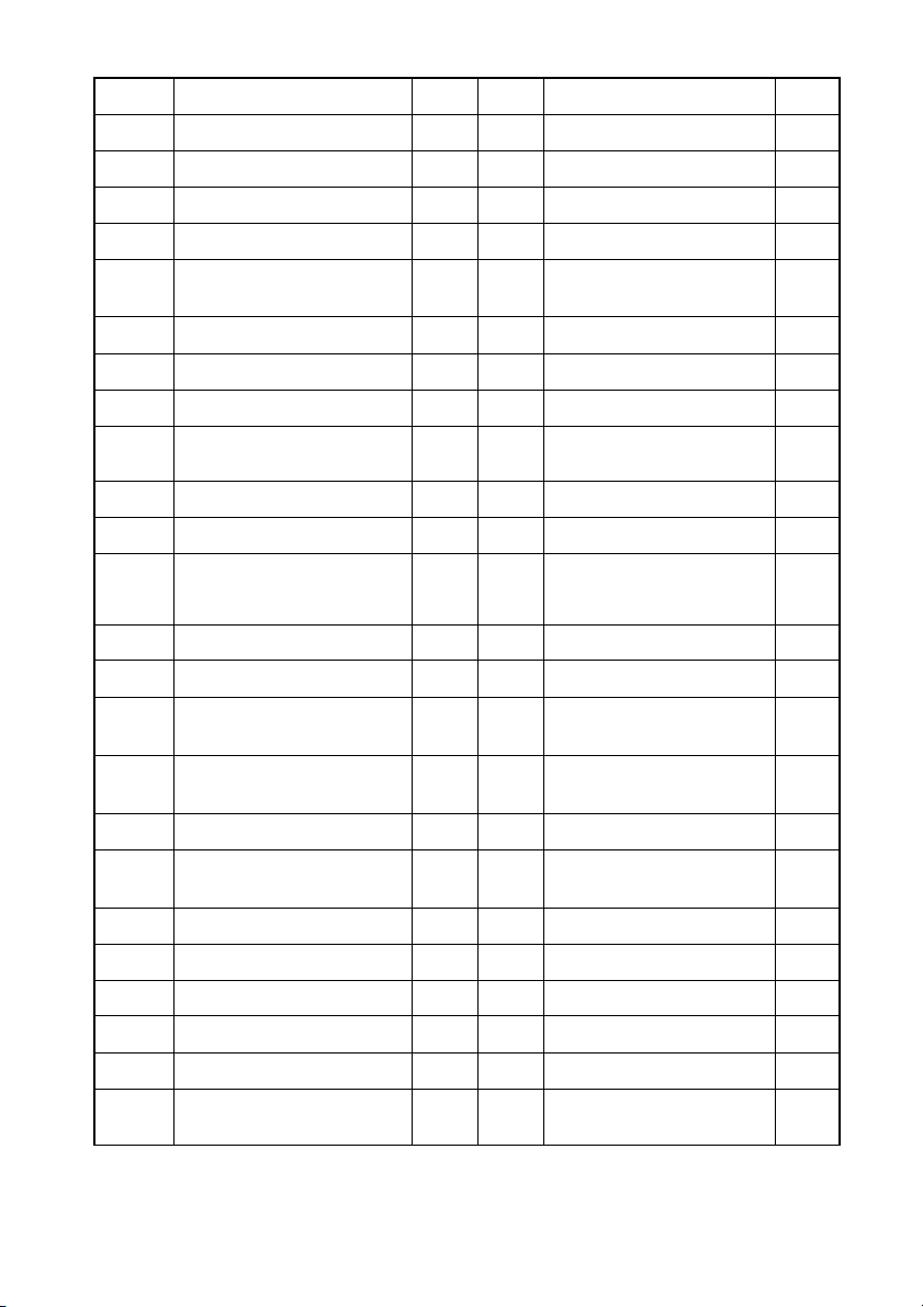
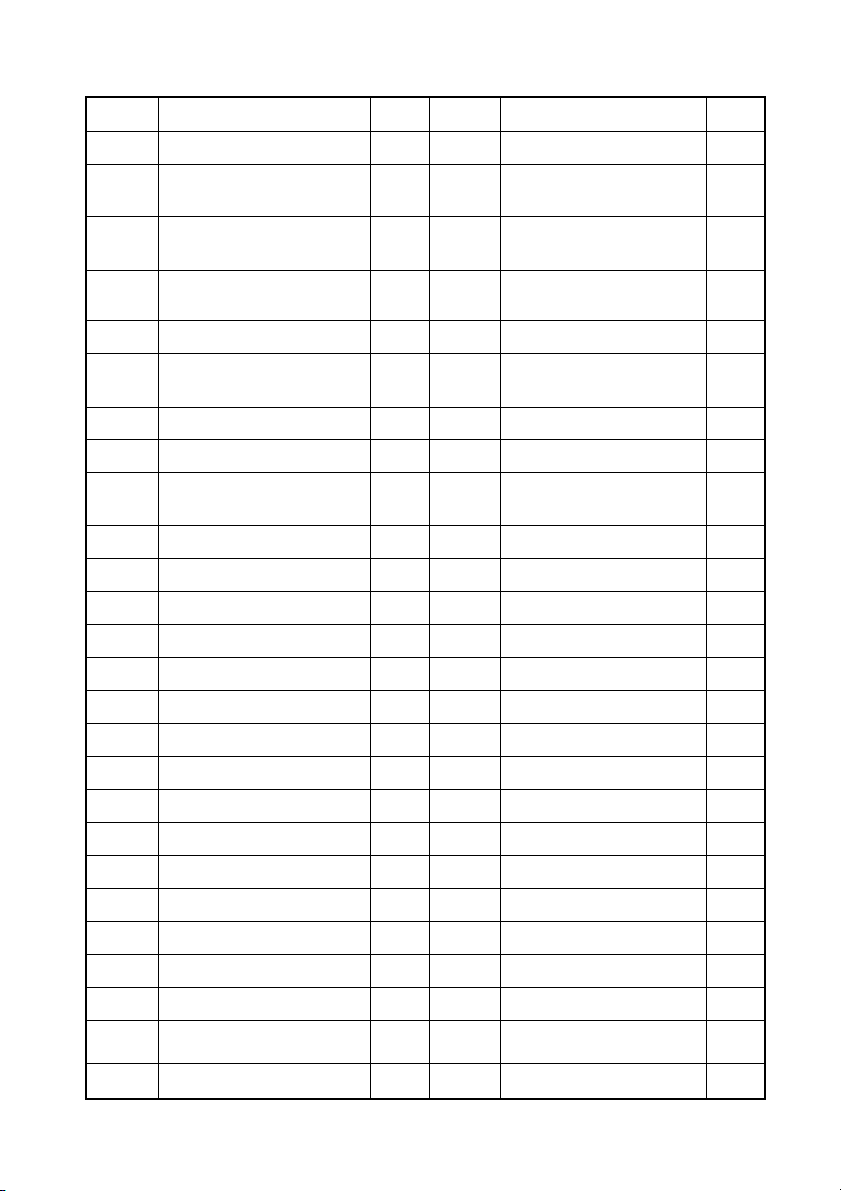
• Prior to assembly, ensure you have all the components and tools listed. Some
components are pre-assembled to help with the assembly process.
• Always use the equipment as intended. If you find any defective components while
assembling or checking the equipment, or if you hear any unusual noises coming from
the equipment during exercise, cease use immediately and contact help.kogan.com for
assistance. Do not use until resolved.
• Do not place fingers or any other objects into moving parts of the exercise equipment.
• Do not exceed the maximum user weight of 120 KG.
Page 4

• Be careful when lifting and moving the equipment. Always use proper lifting technique
and seek assistance if necessary.
• Your equipment is intended for use in cool, dry conditions. You should avoid storage in
extreme cold, hot or damp areas as this may lead to corrosion and other related
problems.
• Operating temperature: 0 - 40 °C
• Storage temperature: -10 - 60°C
• This appliance contains no user-serviceable parts. If it suffers any failure or damage,
cease use immediately and contact help.kogan.com
• This equipment is designed and intended for indoor use only.
Page 5
Page 6
Part
Description
Qty
Part
Description
Qty
1
Computer
x1
25
Bolt M8 x 20 x S6
x4
2
Computer Seat
x1
26
Washer d8 x Φ16 x 1.5
x17
3
Screw M5
x4
27
Front Stabiliser
x1
4
Bolt M8 x 90 x 20 x S13
x1
28
End Cap ZT80 x 40
x4
5
Washer d8 x Φ16 x 1.5
x2
29
Transportation Wheel
Φ48 x 22 x Φ8 x 22
x2
6
Nut M8 x H7.5 x S13
x2
30
Nut M8 x H7.5 x S13
x5
7
Computer Joint Tube
x1
31
Bolt M8 x 42 x 10 x S6
x2
8
Shaft Sleeve
x2
32
Bolt M8 x H5.5 x S14
x5
9L/R
Rowing Rod Pad
x2
33
Foot Pad Φ52 x 43 x
M8
x4
10
Screw ST4.2 x 19 x Φ8
x4
34
Rear Stabiliser
x1
11
Bolt
x1
35
Sliding Rail
x1
12
Shaft Sleeve Φ32 x 3 x
Φ28 x 16 x Φ14.3
x2
36
Bolt Φ10 x 95 x M6 x 25
x1
13
Main Frame
x1
37
Screw M6 x 16 x S5
x1
14
Tension Knob
x1
38
Pull Pin Φ10 x 100 x 105
x1
15
Washer d5 x Φ12 x 1.5
x1
39
Limited Shaft Φ12 x 80
x M6
x1
16
Screw M5 x 30 x Φ8
x1
40
Limited Pad Φ33 x Φ8 x
13
x3
17
L Knob 111 x 22 x 96
x1
41
Washer d6 x Φ12 x 1.2
x3
18
Limited Bracket 27 x 54
x 6.5 PP
x1
42
Screw M6 x 16 x Φ12
x3
19
Washer d12 x Φ24 x 2
x1
43
Grommet Plug Φ16
x1
20
Grommet Plug
x3
44
Inductor
x1
21
Trunk Wire 2
x1
45
Seat
x1
22
T Knob
x1
46
Spring Washer d8
x8
23L/R
Pedal
x2
47
Bolt M8 x 16 x S6
x4
24
Bolt M12 x Φ12.5 x 160 x
23 x S19
x4
48
Right Support Plate
x1
Page 7
Part
Description
Qty
Part
Description
Qty
49
Left Support Plate
x1
75
Screw M5 x 5
x2
50
U Board
x2
76L/R
Shaft Sleeve
Combination
x2
51
Wheel Φ40 x 92
x3
77
Bolt Φ14 x 44 x 17 x M12
x 16
x2
52
Bearing 608Z
x6
78
Screw ST4.2 x 19 x
Φ8.4
x4
53
Spacer d8 x Φ15 x 4
x6
79
Rowing Rod
x2
54
Magnet Φ15 x 7
x1
80
Limited Cushion of
Rowing Rod
x2
55
Bolt M6 x 40 x Φ10 x 2.5
x2
81
Spacer Iron 8 x 7 x 72
x2
56
U Bracket
x2
82
Spacer Iron 6 x 6 x 75
x2
57
Nut M6 x H6 x S10
x6
83
Wave Washer d26 x
Φ34 x 0.3
x3
58
Bolt M8 x 125 x 15 x S14
x3
84
C Clip d25
x4
59L/R
Cover
x2
85
Bearing 6205-ZZ
x2
60
Screw M4 x 10 x Φ6
x6
86
Bolt M8 x 16 x S13
x6
61
Screw ST4.2 x 19 x Φ8
x15
87
Chain Wheel
x1
62L/R
Housing
x2
88
Chain Wheel Shaft
x1
63
Cover
x2
89
Nylon Nut
x8
64
Cover
x2
90
Chain
x1
65
Hole Cover
x2
91
Limited Tube
x1
66
Hole Cover
x2
92
Screw
x2
67
Screw ST4.2 x 16 x Φ8
x6
93
Belt Pulley
x1
68
Screw ST4.2 x 13 x Φ8
x1
94
Belt
x1
69
Screw ST4 x 8 x Φ7
x6
95
Belt Pulley Shaft
x1
70
Screw ST2.9 x 10 x Φ6.3
x4
96
Bolt M6 x 16 x S10
x4
71
Cover
x2
97
Bearing Seat Φ72 x 11
x4
72
Nut M12 x H11 x S19
x4
98
Bearing 6001-2RS
x6
73
Washer d12 x Φ32 x 2.0
x2
99
Fixed Plate t1.5 x 56 x
76
x4
74
Bearing Φ52 x 15 x Φ25
x4
100
Bolt M6 x 12 x S10
x10
Page 8
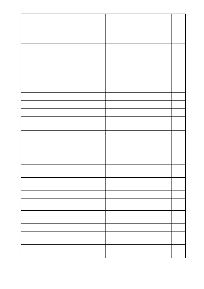
Part
Description
Qty
Part
Description
Qty
101
Screw M6 x 8 x Φ12
x4
123
Spring Φ1.5 x Φ14.5 x 61
x N21
102
Screw M6 x 10 x Φ12
x2
124
Small Chain wheel
103
Magnet Location 45.5 x
130 x 10.5
x1
125
Cover
x2
104
Magnet
x2
126
Cover
x2
105
Screw ST3 x 10 x Φ5.6
x2
127
Trunk Wire 1
x1
106
Adjusting U Plate
x1
128
Bolt M8 x 16 x S6
x4
107
Magnet Fixed Plate
x2
129
Foot Pad Φ38 x 48 x
M8
x1
108
Copper Bush
x6
130
Aluminum Wheel
x1
109
Screw M6 x 20 x Φ10.5
x2
131
Belt Wheel Axle Joint
x1
110
Magnet Fixed Plate
x2
132
Rear Supporting Tube
x1
111
Magnet Φ25 x 10
x1
133
Connecting Rod Joint 2
x1
112
Spring Washer d6
x1
134
Washer d6 x Φ16 x 1.5
x6
113
Bolt M6 x 12 x S10
x1
135
Screw M5 x 7 x Φ10
x2
114
Screw M5 x 10 x Φ10
x1
136
N/A
-
115
Strong Magnet
Connecting Plate
x2
137
Pedal Strap t1.6 x 25 x
850
x2
116
Spring Φ1.2 x Φ13.2 x 62
x N30
x1
138
Screw ST4.2 x 19 x Φ8
x8
117
Idler Wheel Shaft 1
x1
139
Screw M6 x 12 x Φ10.5
x2
118
Spring Φ1.2 x Φ13.2 x 62
x N30
x1
140
Rod Support Plate
x1
119
Bolt M8 x 12 x Φ10 x 5 x
S12
x1 A Spanner S13-14-15
x1
120
Washer d12 x Φ17 x 0.5
x1 B Allen Wrench S6
x1
121
Idler Wheel Φ39 x Φ34 x
24
x1 C Allen Wrench S5
x1
122
Wave Washer d12 x
Φ15.5 x 0.3
x1 D Spanner S17-19
x1
Page 9
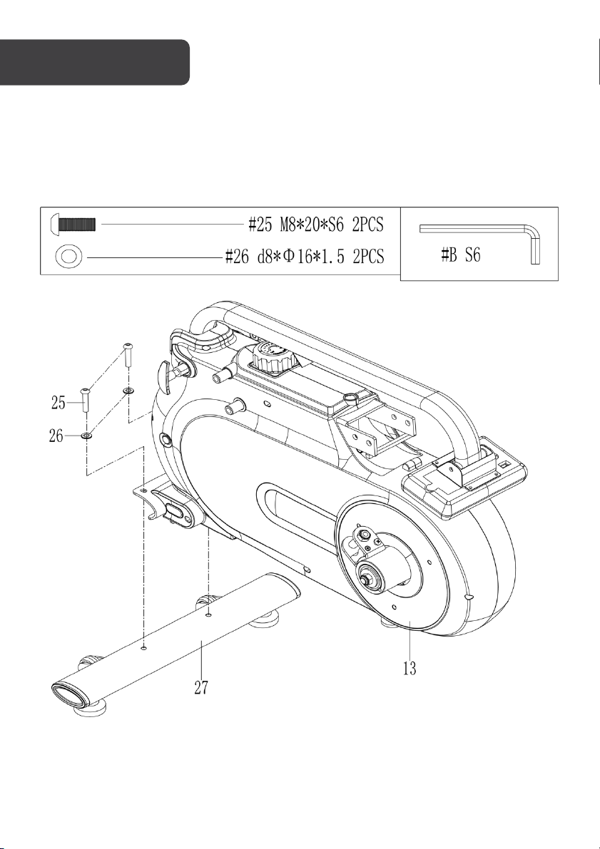
Step 1:
Attach Front Stabiliser (27) to Main Frame (13) with x2 Bolts (25) and x2 Washers (26).
Tighten and secure with the Allen Wrench (B).
Page 10
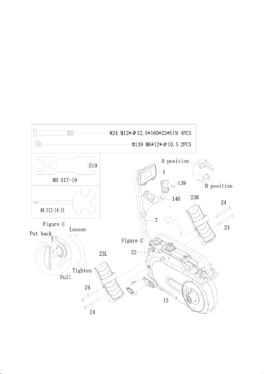
Step 2:
Loosen T Knob (22) as shown in Figure C and pull outward. Next, rotate Computer Joint
Tu b e (7) to the desired position and screw T Knob (22) into the hole. Finally, adjust Computer
(1) up and down to the proper angle.
Insert x2 Bolts (24) into the bottom hole at position B of Main Frame (13). Tighten with
Spanner (D).
Insert x2 Bolts (24) through the Pedals (
Frame (13). Tighten with Spanner (D).
NOTE: The Pedals (
Remove x2 Screws (
Attach Rod Support Plate (
removed. Tighten and secure with Spanner (A).
23L/R
) should rest on the bottom Bolts (24) at position B.
139
) from Computer Joint Tube (7) with Spanner (A).
140
) to Computer Joint Tube (7) with x2 Screws (
23L/R
) into the upper hole at position A of Main
139
) that were
Page 11
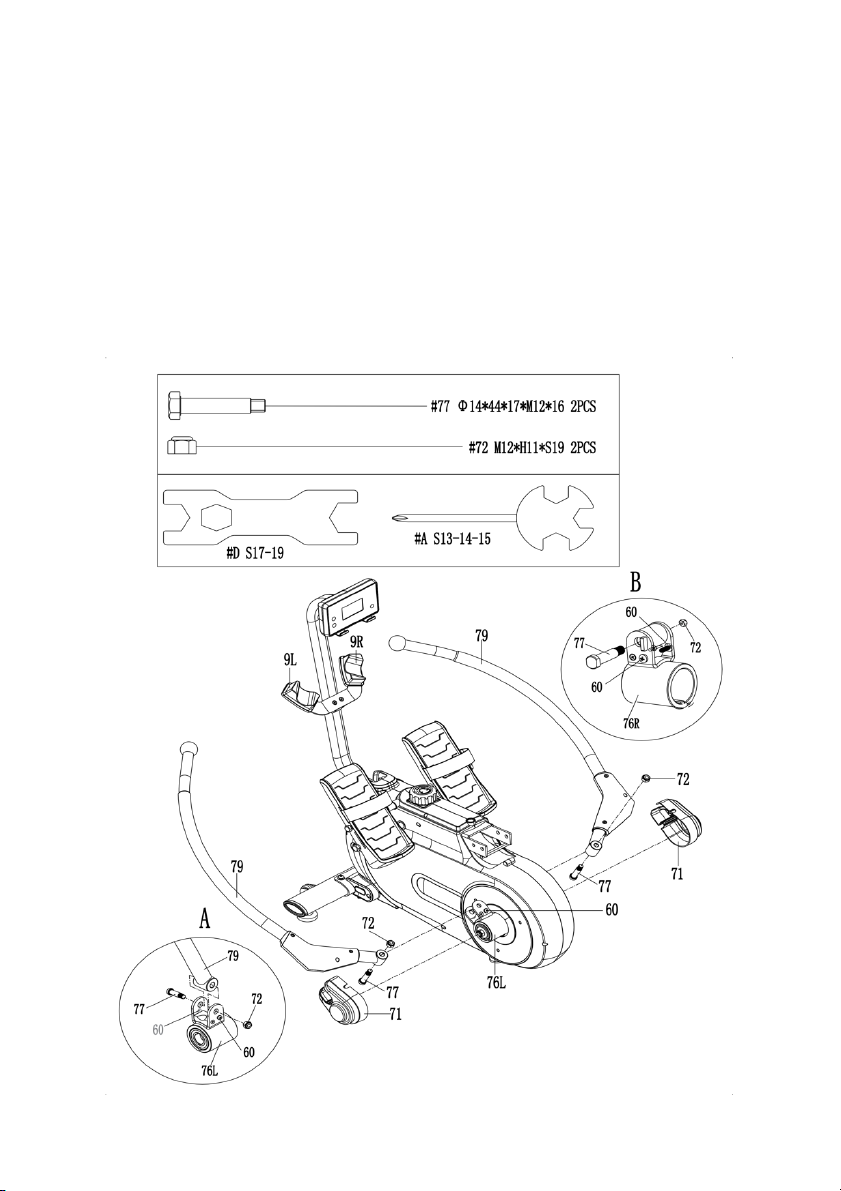
Step 3:
Loosen x4 Screws (60) from Left & Right Shaft Sleeve Combinations (
76L/R
) with Spanner
(A).
Remove x2 Bolts (77) and 2 Nuts (72) from Left & Right Shaft Sleeve Combinations (
76L/R
with Spanner (D).
Put Rowing Rods (79) into Left & Right Shaft Sleeve Combinations (
76L & 76R
) with x2 Bolts
(77) and x2 Nuts (72) that were removed. Tighten and secure with Spanner (D).
Note: Please check if Rowing Rod (79) rotates smoothly. If not, Bolt (77) and Nut (72) are
locked too tight. Adjust Nut (72) with Spanner (D) to make the rotation smooth.
Put Rowing Rods (79) on Left & Right Rowing Rod Pads (
Left & Right Shaft Sleeve Combinations (
76L & 76R
9L & 9R
). Put x2 Covers (71) into
) with x4 Screws (60) that were loosened.
Tighten and secure with Spanner (A).
)
Page 12
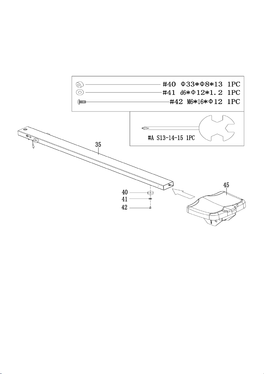
Step 4:
Insert Seat (45) to Sliding Rail (35).
Attach Limited Pad (40) to Sliding Rail (35) with Screw (42) and Washer (41). Tighten and
secure with the Spanner (A).
Page 13
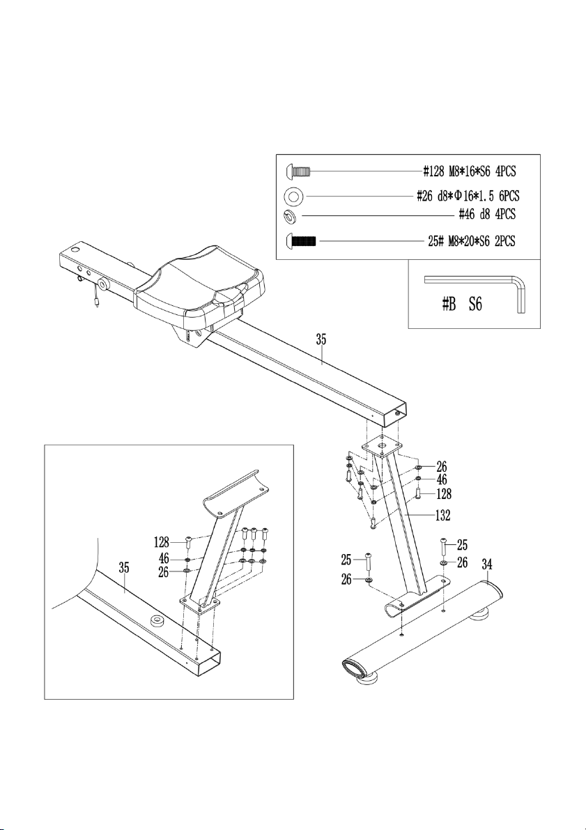
Step 5:
Attach Rear Supporting Tube (
132
) to Sliding Rail (35) with x4 Bolts (
128
(46) and x4 Washers (26). Tighten and secure with the Allen Wrench (B).
Attach Rear Stabiliser (34) to Rear Supporting Tube (
132
) with x2 Bolts (25) and x2 Washers
(26). Tighten and secure with the Allen Wrench (B).
), x4 Spring Washers
Page 14
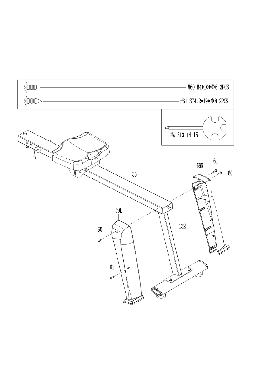
Step 6:
Attach Left & Right Covers (
59L & 59R
then lock Left & Right Covers (
Spanner (A).
Attach Left & Right Covers (
59L & 59R
secure with Spanner (A).
59L & 59R
) to Sliding Rail (35) and Rear Supporting Tube (
) to Sliding Rail (35) with x2 Screws (60). Tighten and
) with x2 Screws (61). Tighten and secure with the
132
),
Page 15
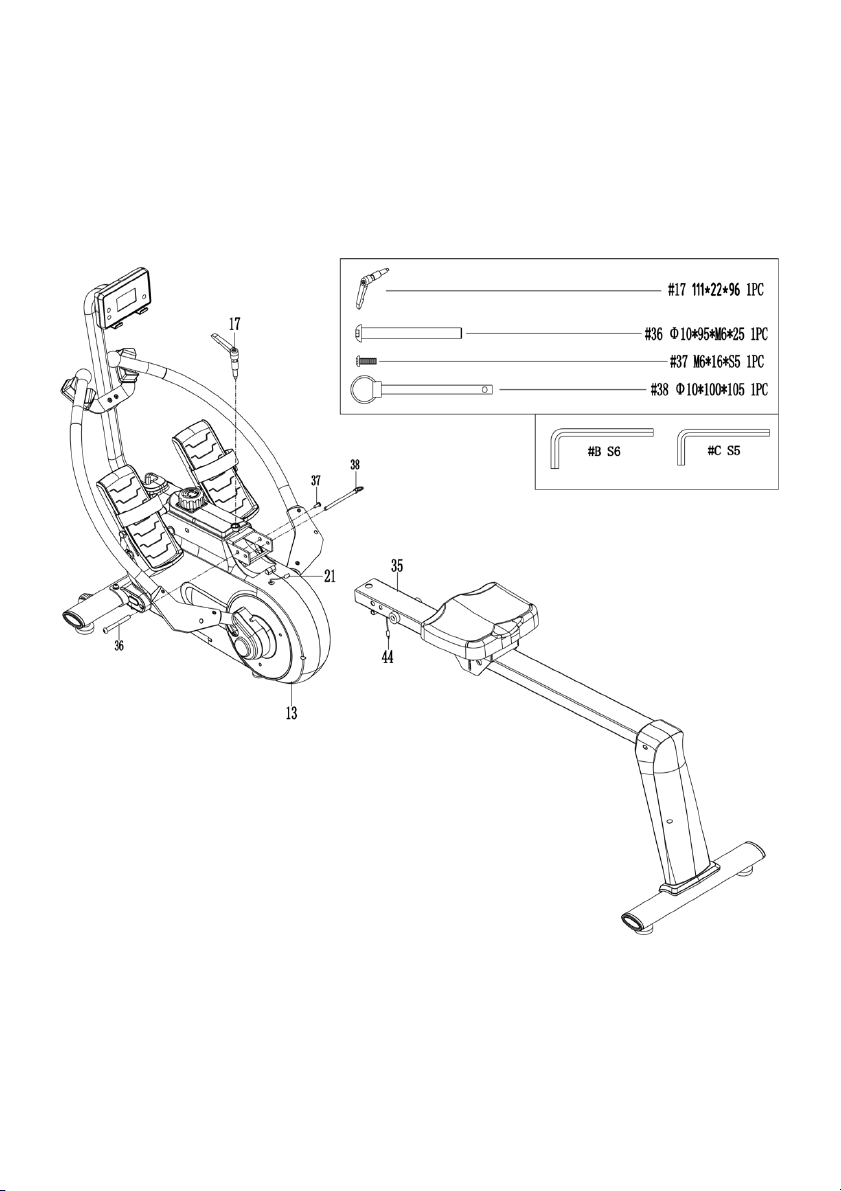
Step 7:
Attach Sliding Rail (35) to Main Frame (13) using Bolt (36) and Screw (37). Tighten and
secure with Allen Wrench (B) and Allen Wrench (C). Then insert Pull Pin (38).
Next, attach the top of Sliding Rail (35) to Main Frame (13) using L Knob (17).
Connect the link wire of Inductor (44) with Trunk Wire 2 (21).
Page 16
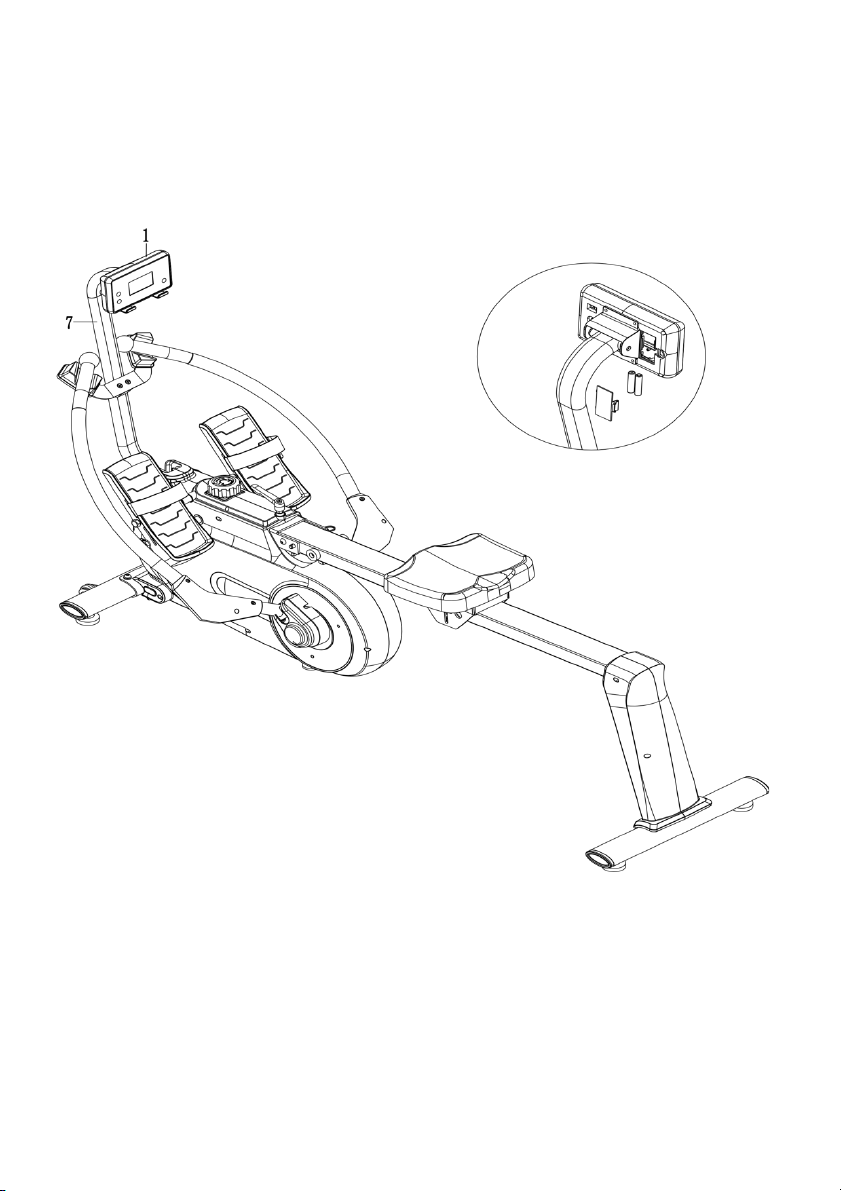
Step 8:
Open the battery cover on the back of Computer (1), then put x2 “AAA” batteries into the
battery case. Make sure the (-) end of the battery goes to the spring end in the battery
compartment, then put the battery cover back.
Page 17
Loosen
Figure A
Pull
Push
Figure B
Pull
Tighten
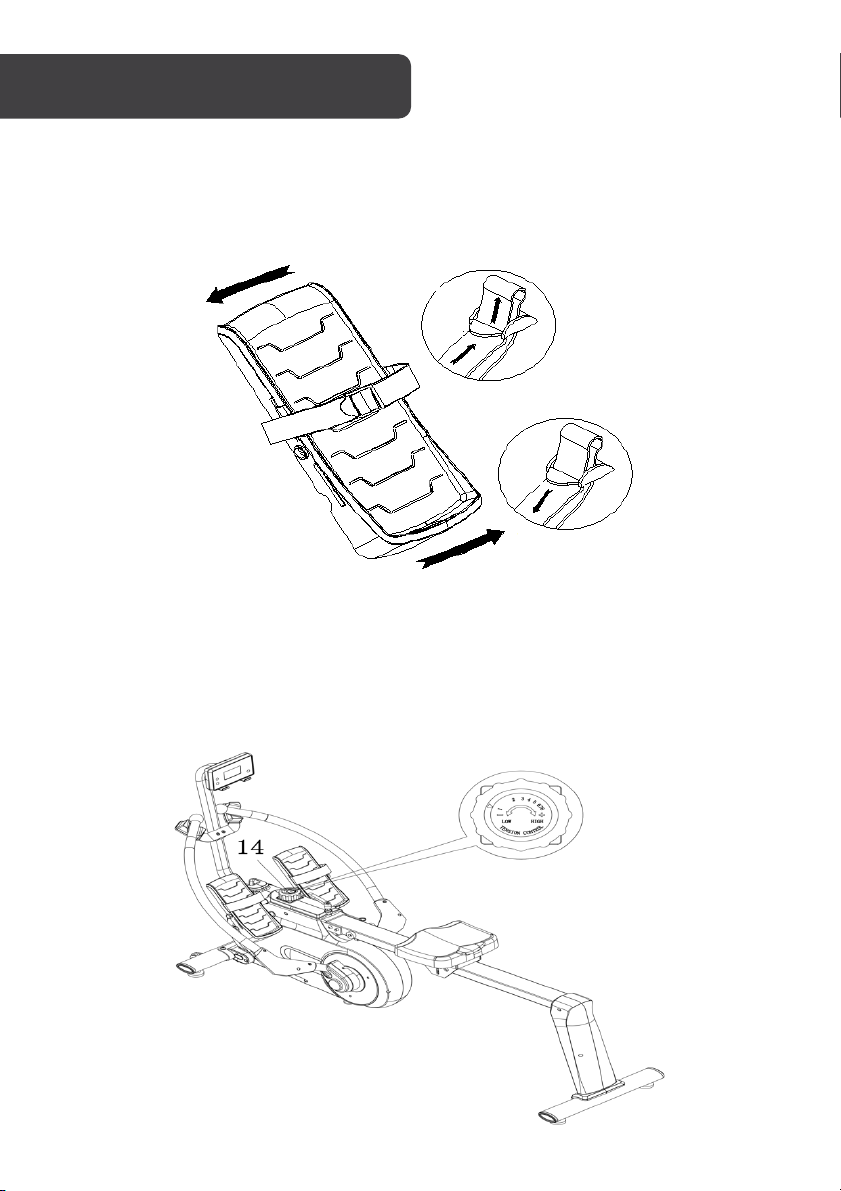
Pedal Strap Adjustment
The Pedal Strap (
137
) is adjustable and can be adjusted to fit the user’s foot size. Directions
on how to loosen and tighten the straps are shown in Figures A and B.
Adjusting the Resistance
Rotate the Tension Knob (14) clockwise to increase the level of resistance. Rotate the Tension
Knob (14) counter-clockwise to decrease the level of resistance.
Te n s i o n l e v e l s a r e s e t a t L e v e l 1 b e i n g t h e l o w e s t a n d L e v e l 8 b e i n g t h e h i g h e s t .
Page 18
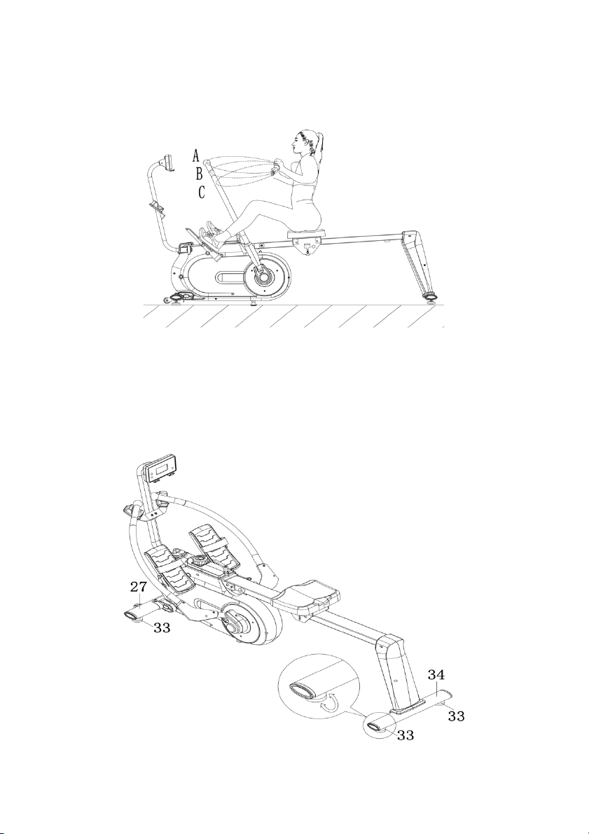
Adjusting the Resistance of the Rowing Rod
The resistance is different at positions A, B, C, etc. The closer you are to positions A, the
lighter the resistance.
Adjusting the Balance
In order to achieve a smooth and comfortable ride, you must ensure that the stability of the
rower is secured. If you notice that the rower is unbalanced during use, you should adjust the
Foo t Pa ds (33) located beneath the Front & Rear Stabilisers (
27 & 34
). To do so, simply
rotate the Foot Pads (33) until the rower becomes level with the floor surface.
Page 19

Key Fu nc tio n:
MODE: Press this button to change the display or to choose a program.
SET: In the setting mode, press this button to increase the setting value for TIME, COUNT
and CAL.
Reset:
1. In setting mode, press this button to reset the value for TIME, COUNT and CAL.
2. In monitor mode, hold this button for 3 seconds to reset all values to zero.
Fun ct ion
• SCAN: Press MODE until “SCAN” appears, the computer will rotate through all the
four functions: Time, Count, Cal, Total Count. Each display will be held for 6
seconds.
• COUNT (CNT): Displays an instant count with a range from 0 ~ 9999 COUNT. The
count value can be set in advance, when it approaches the preset count, the
computer will beep for 10 seconds.
• TIME: Counts the total time from exercise start to the end with a range from 0:00 ~
99:59 minutes. Exercise time can be set in advance, when it approaches the preset
time, the computer will beep for 10 seconds. The maximum preset time is 99
minutes.
• CALORIES (CAL): Counts the total calories burned from exercise start to the end
with a range from 0.0 ~ 9999 calories. The calorie value can be set in advance,
when it approaches the preset calorie, the computer will beep for 10 seconds.
• TOTAL COUNT (TOTAL): Displays the total count from the first use. The range is
from 0 ~ 9999 COUNT.
• AUTO ON/OFF & AUTO START/STOP: When there is no signal of exercise or
operation for 4 minutes, the power will turn off automatically. Once motion begins,
the computer will turn on automatically.
Operation:
• SET: Press MODE to choose the display window that needs to be pre-set. Press
SET to increase the value to reach your desired time, calorie or count. Hold SET to
increase the value. Press RESET to reset values.
• BATTERY: When the display screen light begins to fade, remove the batteries and
replace with x2 “AAA” batteries.
Page 20
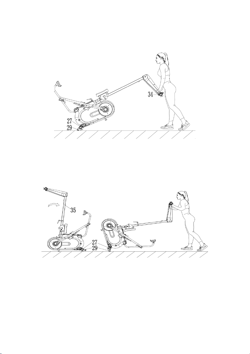
Moving the Rower
To m o v e t h e r o w e r , l i f t u p R e a r S t a b i l i s e r (34) until the Transportation Wheels (29) on Front
Stabiliser (27) touch the ground. Once the Transportation Wheels (29) are on the ground, you
can transport the rower to the desired location with ease.
Moving the Rower After Folding
Press the Sliding Rail (35) down until Transportation Wheels (29) on Front Stabiliser (27)
touch the ground. Once the Transportation Wheels (29) are on the ground, you can
transport the rower to the desired location with ease.
Page 21
Fol di ng the Rower
Loosen
Tighten
Figure A
Figure B
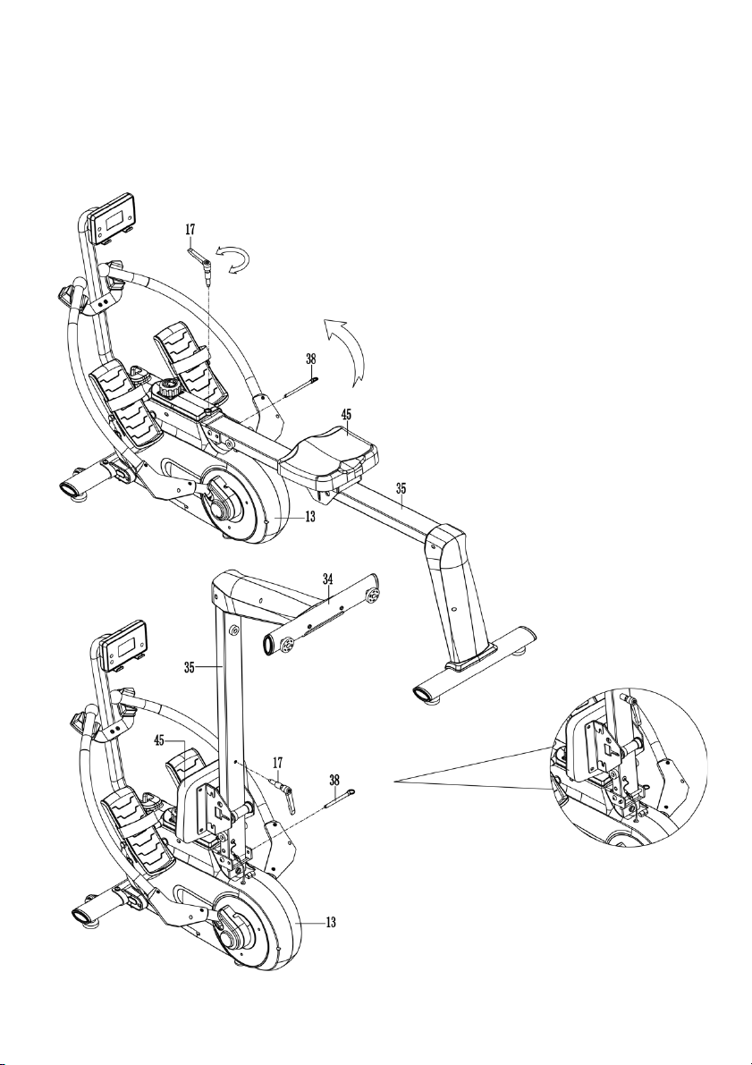
When not in use, the rower can be folded to save space. Disassemble L Knob (17) and pull
out Pull Pin (38) from Main Frame (13). Lift the Sliding Rail (35) up 90 degrees. Shown in
Figure A.
Re-insert Pull Pin (38) into the hole on Main Frame (13), then tighten L Knob (17) to Sliding Rail
(35) (Figure B).
Page 22
Battery Replacement
Battery
Battery Cover
1
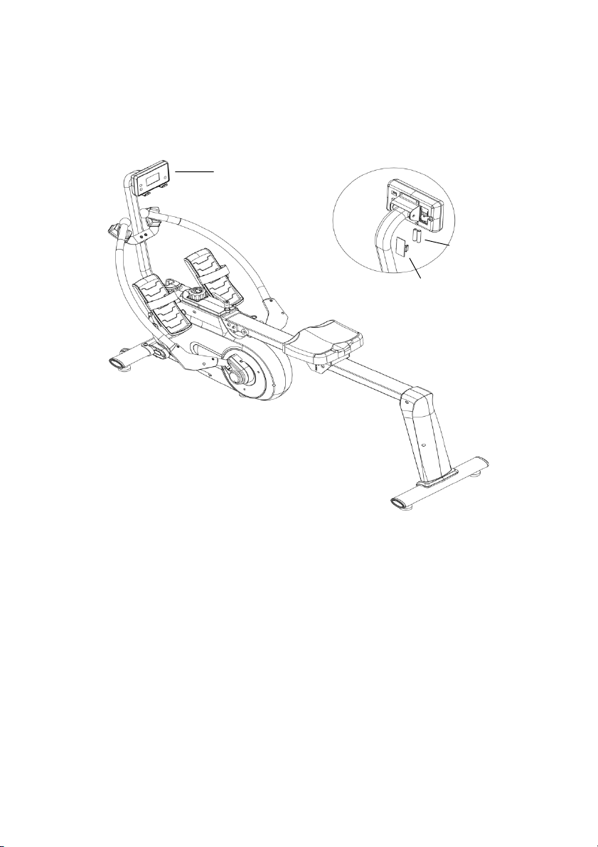
To r e p l a c e t h e b a t t e r i e s , o p e n t h e b a t t e r y c o v e r o n t h e b a c k o f t h e C o m p u t e r (1). Remove the
batteries and replace with new “AAA” batteries. Make sure the (-) end of the battery goes to
the spring end in the battery compartment. Put the cover back.
When changing batteries, always replace both with new batteries. Do not mix old and new
batteries.
Page 23
Page 24

Need more information?
We hope that this user guide has given you
the assistance needed for a simple set-up.
For th e mo st up -to-date guide for your product,
as well as any additional assistance you may require,
head online to help.kogan.com
 Loading...