

Page 1
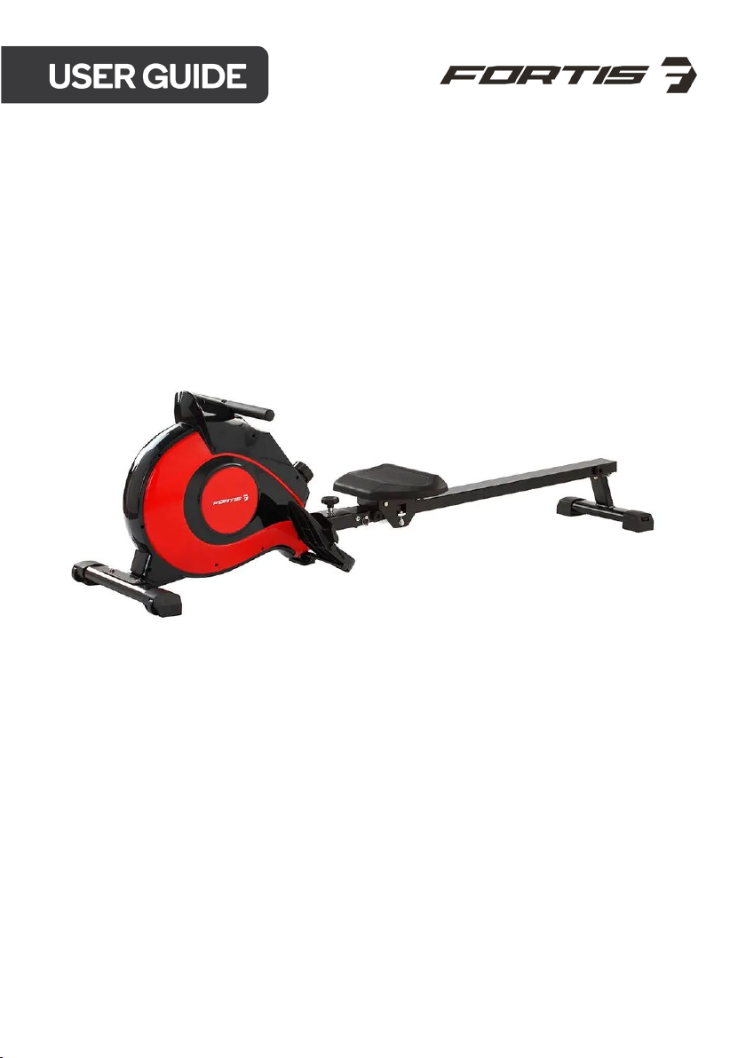
MAGNETIC FLYWHEEL
ROWING MACHINE
(FSFWRWGMC1A)
Page 2

Safety & Warnings 3
Overview 5
Assembly 10
Adjustments 15
Function 19
Notes 22
2
Page 3

SAFETY & WARNINGS
• Read all instructions before using the equipment and retain for reference.
• Before starting any exercise programme, consult your physician to determine if you
have any medical or physical conditions that could put your health and safety at risk or
prevent you from using the equipment properly. Your physician’s advice is essential if
you are taking any medication that may affect your heart rate, blood pressure or
cholesterol level.
• Follow your body’s signals. Incorrect or excessive exercise can damage your health.
Stop exercising and consult your physician before continuing with your exercise
program if you experience any of the following symptoms: pain, tightness in your chest,
irregular heartbeat, shortness of breath, light headedness, dizziness or feelings of
nausea.
• Keep away from children and pets. This appliance is not intended for use by persons
(including children) with reduced physical, sensory or mental capabilities or lack of
experience and knowledge, unless they have been given supervision or instruction
concerning use of the appliance by a person responsible for their safety.
• Use on a solid, flat level surface with a protective cover for your floor or carpet. Leave at
least 70cm clearance around the equipment.
• Ensure that all nuts and bolts are securely tightened before using the equipment.
Examine regularly for damage and/or wear and tear.
• It is recommended that you lubricate all moving parts on a monthly basis.
• Wear suitable clothing while using the equipment. Avoid wearing loose clothing that
may become entangled in the equipment.
• Do not place fingers or objects into the moving parts of the equipment.
• Observe the maximum weight capacity (120kg, subject to change).
• This equipment is not suitable for therapeutic use.
• Move with caution when lifting and moving the equipment. Always use proper lifting
technique and seek assistance if necessary.
• This product is intended for use in cool, dry conditions. Avoid storage in extreme cold,
hot or damp areas as this may lead to corrosion and other related problems.
• Always use the equipment as indicated. If you find any defective components while
assembling or checking the equipment or if you hear any unusual noises coming from
the equipment during exercise, stop using the equipment immediately and contact
help.kogan.com for support.
3
Page 4
Transportation
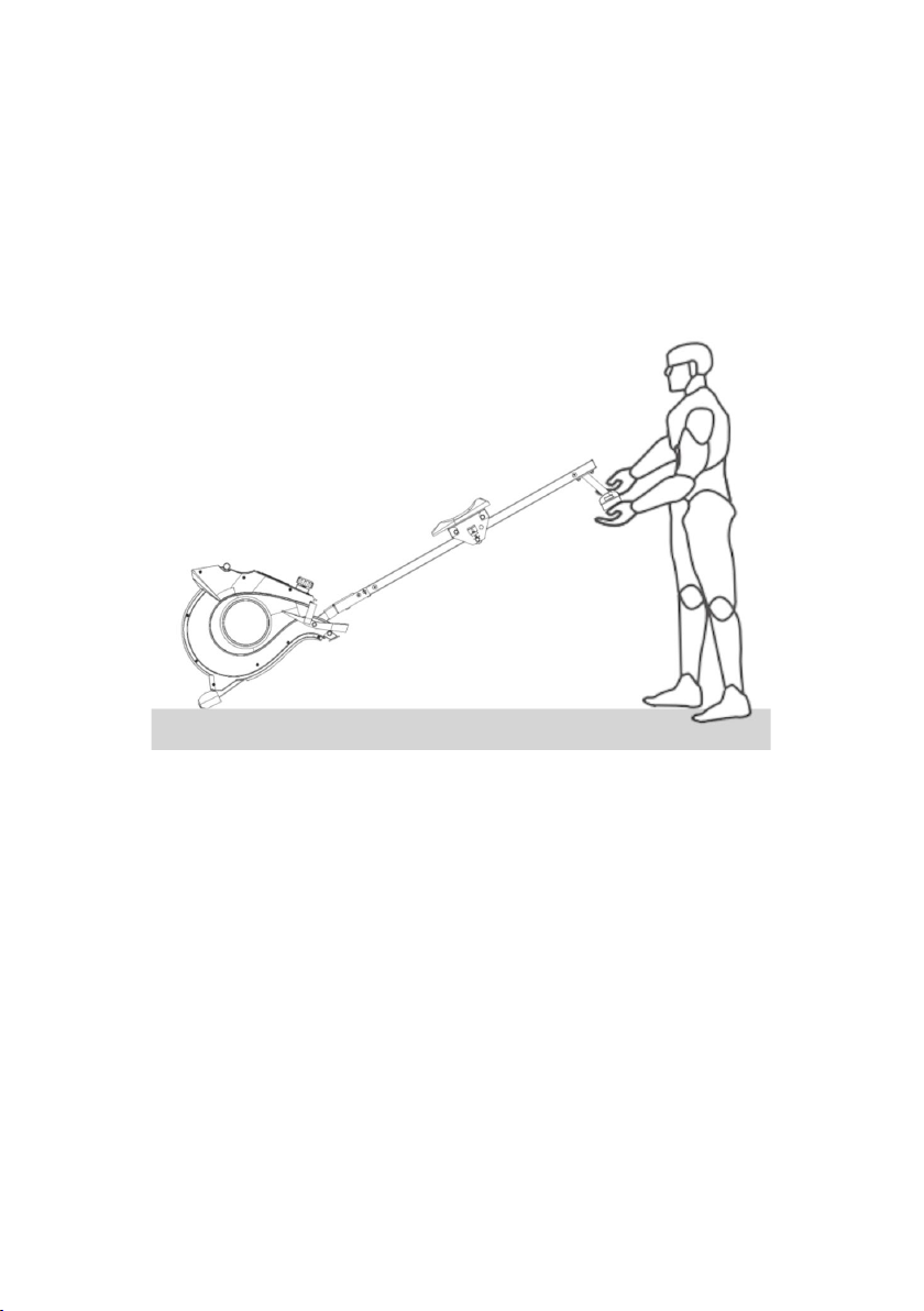
To move the rowing machine, lift the rear stabiliser until the transportation wheels on the
front stabiliser touch the ground. With the wheels on the ground, you can transport the
rowing machine to the desired location with ease.
4
Page 5
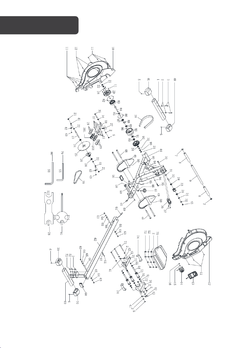
OVERVIEW
5
Page 6
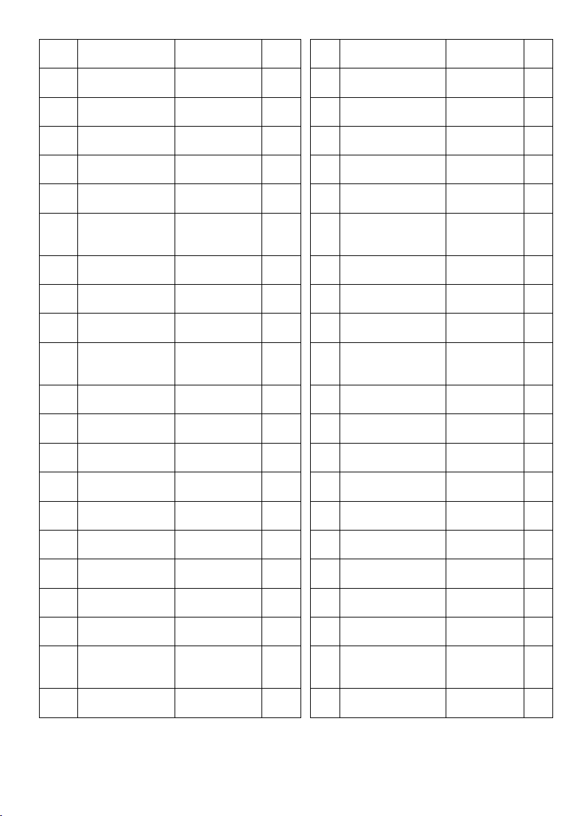
No. Description Spec.
Qty
No. Description Spec. Qty
1 Front stabilizer 1
2 Washer d8*Φ16*1.5 16 50 Pedal strap 2
3 Screw M8*55*20*S6 2 51 Magnet Φ15*7 1
4 End cap 2
5 Nut M8*H7.5*S6 3
6 Screw ST4.2*25*Φ10.5 4
7 Handlebar 1
8 Foam grip Φ23*3*180 2 56 Rubber pad M8*H5.5*S14 1
9 End cap Φ25*16 2
10 Left chain cover 1
11 Screw ST4.2*19*Φ8 11
12 Screw ST4.2*19*Φ8 6
13 Computer 1 61 Sensor wire 1
49 Pedal L/R 2
52 Spring washer S8 8
53 Wheel Φ40*92 3
Casing pipe for idler
54
55 Bearing 608Z 6
57 Right chain cover 1
58 Bolt
59 Screw M6*16*S5 1
60 Pull pin Φ8*100*105 1
wheel
Φ14*8*78 3
Φ10*95*M6*2
5
1
14 Tension control 1
15 Washer D5 1
16 Screw M5 1 64 Washer S6*Φ12*1 4
17 Screw ST3*10*Φ5.6 10
18 Magnetic plate 1 66 Limit axle Φ12*80*M6 2
19 Magnet 39*24.5*10 6
20
Magnet location
L/R
21 Nut M10*1*H8*S15 4
grid
112.4*60.6*10.2 2
62 Sliding rail 1
63 Screw M6*16*Φ12 4
65 Limit mat Φ33*Φ8*13 4
67 Grommet Φ12*11*Φ3 1
68 End cap J80*40*18 1
69 Rear support 1
6
Page 7
No. Description Spec.
Qty
No. Description Spec. Qty
22 Nut M10*1*H5*S18 3
23 Axle
24 Bearing 6000-ZZ 4
25 Aluminium wheel t4.0*Φ200*Φ30 1
26 Shaft sleeve Φ33*45 1 74 U shape baffle 2
27 Spring
28 Washer d10*Φ20*1.5 1
29 Cover Φ118.5*11.8 1 77 Spacer d8*Φ15*4 6
30 Bolt M6*55*15*S10 1
31 Circlip for shaft d10 3
32 Axle Φ10*40*Φ6.1 1 80 Allen wrench S6 1
33 Pulley Φ45*35 1 81 Spanner S13-15-15 1
Φ12*132*M10*1.
0*24
Φ1.5*Φ15*54*N
9
70 End cap 2
1
71 Saddle DDPU986 1
72 Screw M8*20*S6 8
73 Bolt
Left seat supporting
1
75
76
78 Spanner S17-19 1
79 Allen wrench S5 1
board
Right seat
supporting board
M8*125*15*S1
4
1
1
3
34 Wave washer d10*Φ13.5*0.3 2
35 Bolt
36 Handlebar seat 1
37 Screw M5*10*Φ10 2 85 Wave washer d10*Φ15.5*0.3 1
38 Mesh belt t1.3*18*2140 1
39 Belt 1 87 Bearing 6300-2RS 1
40 Bolt M6*55*S10 1
Φ10*72*M8*12.5
*S17
82 PC Sheet Φ111*Φ16*0.5 1
1
83 Spiral spring t0.5*22*5080 1
84 Axle
86 PC Sheet
88 Circlip for Hole d35 1
Φ10*130*M10*
Φ89.5*Φ16*0.
1.0
5
7
1
1
Page 8
No. Description Spec. Qty No. Description Spec. Qty
41 Adjusting screw M6 *40*Φ10*2.5 4 89 Bearing 16003-2RS 2
42 Adjusting U seat 32*10*1.5 4
43 Nut M6*H6*S10 7
44 Main frame 1 92 Belt pulley 1
45 Trunk wire 1 1
46 Washer d12*Φ24*2 1
47 Knob M12 1 95 Bolt M6*45*S10 1
48 Bolt
M12*Φ12.5*160*
23*S19
90 Braid wheel Φ112*67.5 1
91 Bearing Φ35*d17*16 1
93 Nut M10*1*H3*S14 1
94 Nut M6*H5*S10 2
4
96 Axle Φ5*43 1
8
Page 9
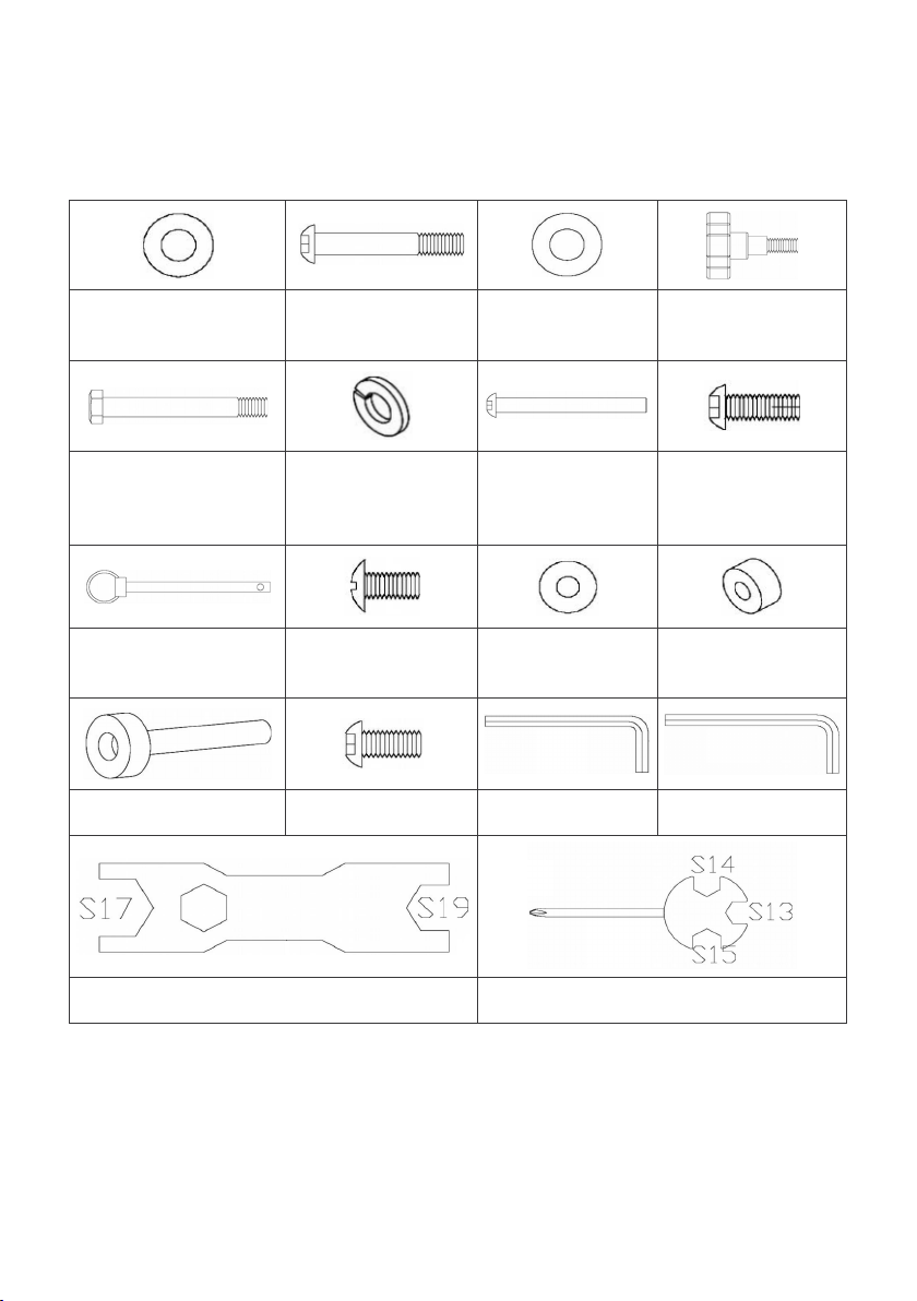
Included Hardware
#2 d8*Φ16*1.5 (x6)
#48
M12*Φ12.5*160*S19
(x4)
#60 Φ8*100*105 (x1) #63 M6*16*Φ12 (x1) #64 d6*Φ12*1 (x1)
#66 Φ12*80*M6 (x1) #72 M8*20*S6 (x4) #79 S5 #80 S6
#3 M8*55*20*S6
(x2)
#52 d8 (x4)
#46 d12*Φ24*2
(x1)
#58
Φ10*95*M6*25
(x1)
#47 M12 (x1)
#59 M6*16*S5 (x1)
#65 Φ33*Φ8*13
(x1)
#78 #81
9
Page 10
ASSEMBLY
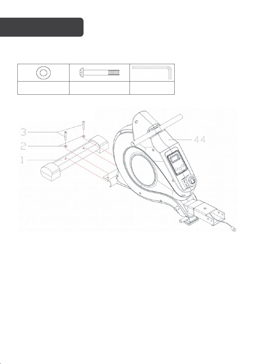
Step 1:
#2 d8*Φ16*1.5 (x2) #3 M8*55*20*S6 (x2) #80 S6
Attach the Front Stabilizer (No. 1) to the Main Frame (No. 44) using 2x Screws (No. 3) and 2x
Washers (No. 2). Tighten and secure with Allen Wrench (No. 80).
10
Page 11
Step 2:
Note:
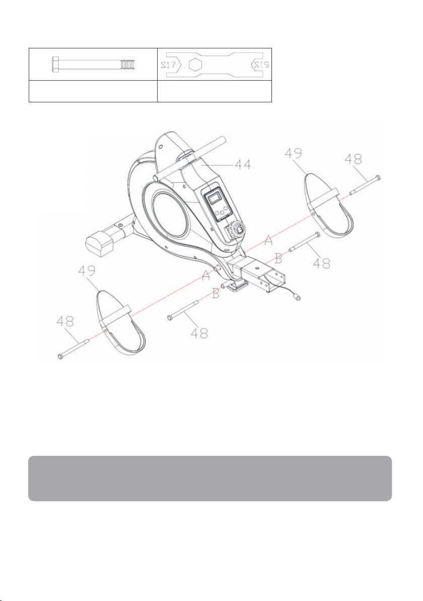
#48 M12*Φ12.5*160*S19 (x4) #78
Fix the 2 Bolts (No. 48) into the bottom hole in position B of Main Frame (No. 44) with
Spanner (No. 78).
Attach the 2 Bolts (No. 48) into the upper hole in position A of the Main Frame (No. 44)
through the Pedals (No. 49) and tighten with Spanner (No. 78).
The Pedals (No.49) should rest on the Bolts (No.48) that are in position B.
11
Page 12
Step 3:
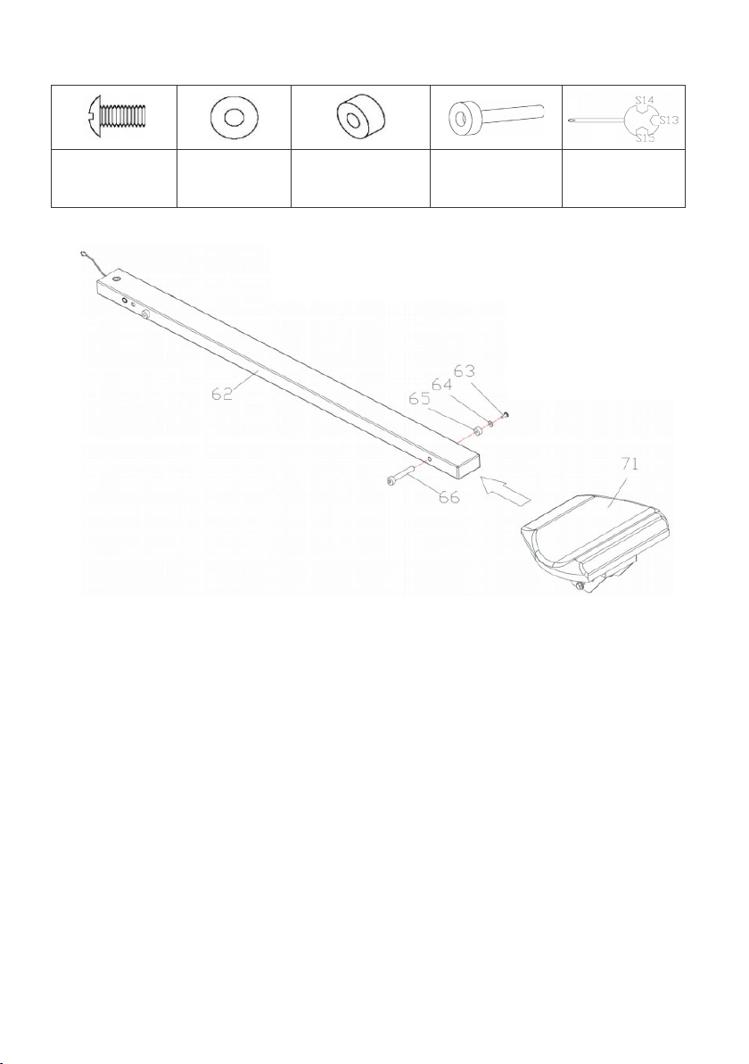
#63 M6*16*Φ12
(x1)
Insert the Saddle (No. 71) into the Sliding Rail (No. 62).
Insert the Limit Axle (No. 66) into the hole on the back of the Sliding Rail (No. 62). Attach
the Limit Mat (No. 65) onto the Limit Axle (No. 66) using 1x Screw (No. 63) and 1x Washer
(No. 64) then tighten with Spanner (No. 81).
#64 d6*Φ12*1
(x1)
#65 Φ33*Φ8*13
(x1)
#66 Φ12*80*M6
(x1)
#81
12
Page 13
Step 4:
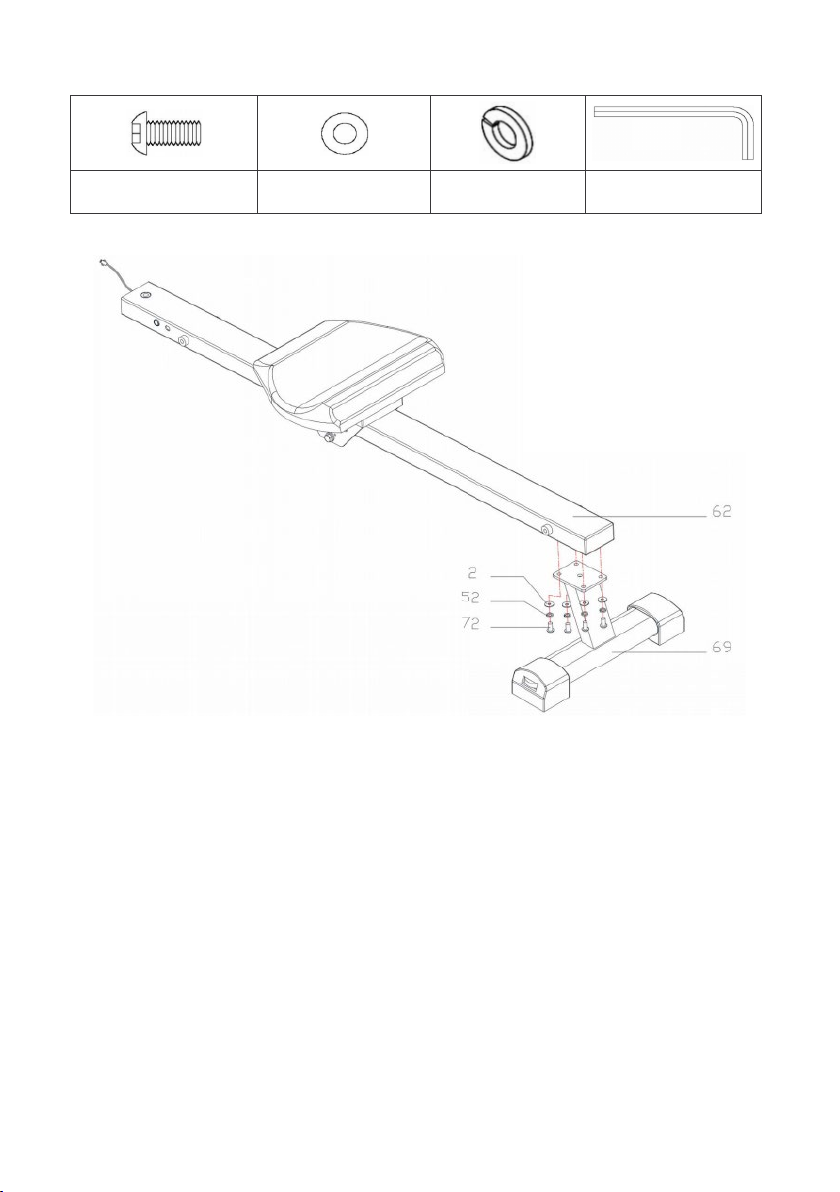
#72 M8*20*S6 (x4) #2 d8*Φ16*1.5 (x4) #52 d8 (x4) #80 S6
Attach the Sliding Rail (No. 62) onto the Rear Support (No. 69) using 4x Screws (No. 72), 4x
Spring Washers (No. 52) and 4x Washers (No. 2). Tighten and secure with Allen Wrench
(No. 80).
13
Page 14
Step 5:
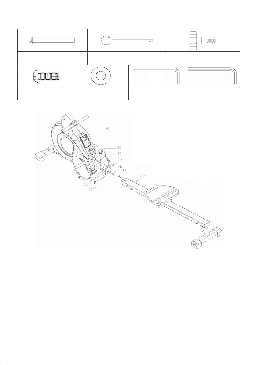
#58 Φ10*95*M6*25 (x1) #60 Φ8*100*105 (x1) #47 M12 (x1)
#59 M6*16*S5 (x1) #46 d12*Φ24*2 (x1) #79 S5 #80 S6
Connect Trunk Wire 1 (No. 45) to the Sensor Wire (No. 61).
Attach the Sliding Rail (No. 62) to the Main Frame (No. 44) using 1x Bolt (No. 58) and 1x
Screw (No. 59).
Tighten and secure with Allen Wrench (No. 79) and Allen Wrench (No. 80).
Next, attach the top of the Sliding Rail (No. 62) to the Main Frame (No. 44) using 1x Knob
(No. 47) and 1x Washer (No. 46), then insert the Pull Pin (No. 60).
Assembly is now complete.
14
Page 15
ADJUSTMENTS
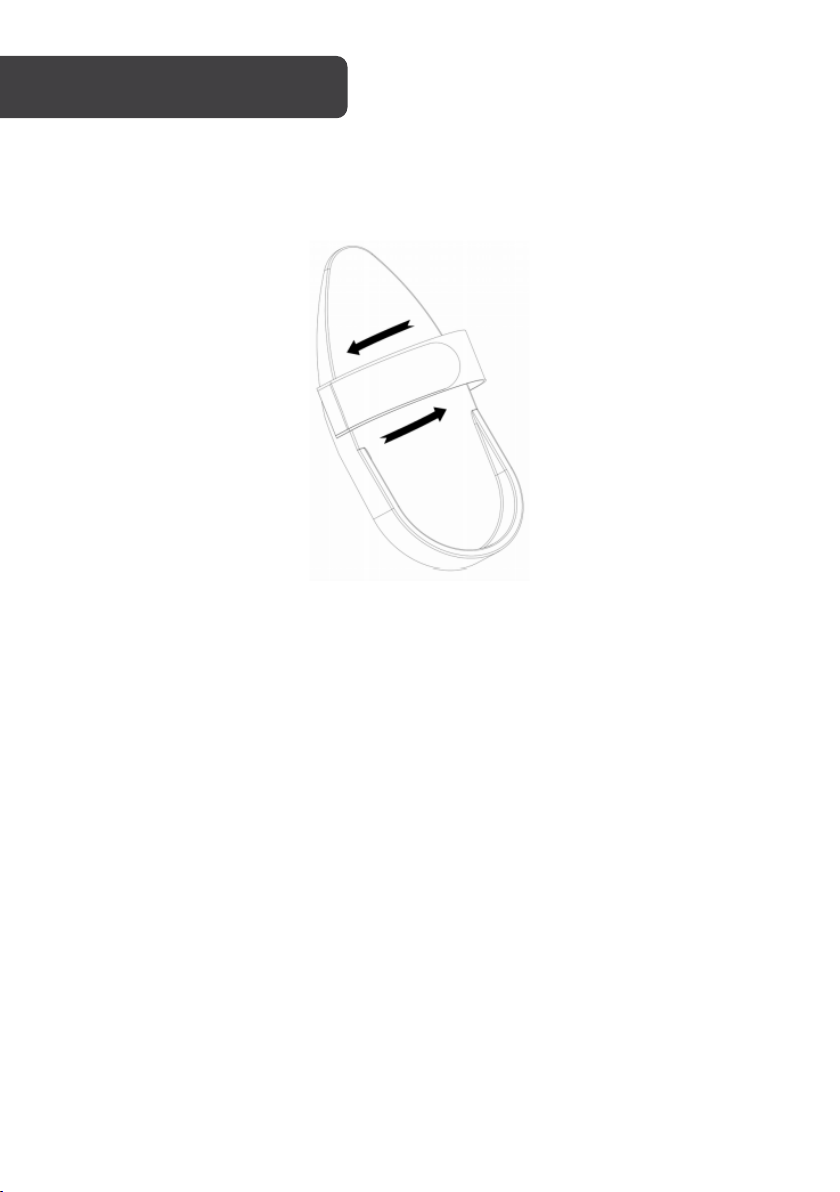
Pedal Adjustment
The pedal strap is adjustable and can be personalised to fit the user’s foot size.
To adjust the pedal strap, remove the Velcro end of the strap from the mesh side by pulling
it upward then to the left.
Once removed, you may increase the opening of the pedal strap by pulling the mesh end
up and to the right.
To tighten, pull the Velcro end of the pedal strap upward then to the right and down to
secure it to the mesh side of the strap.
15
Page 16
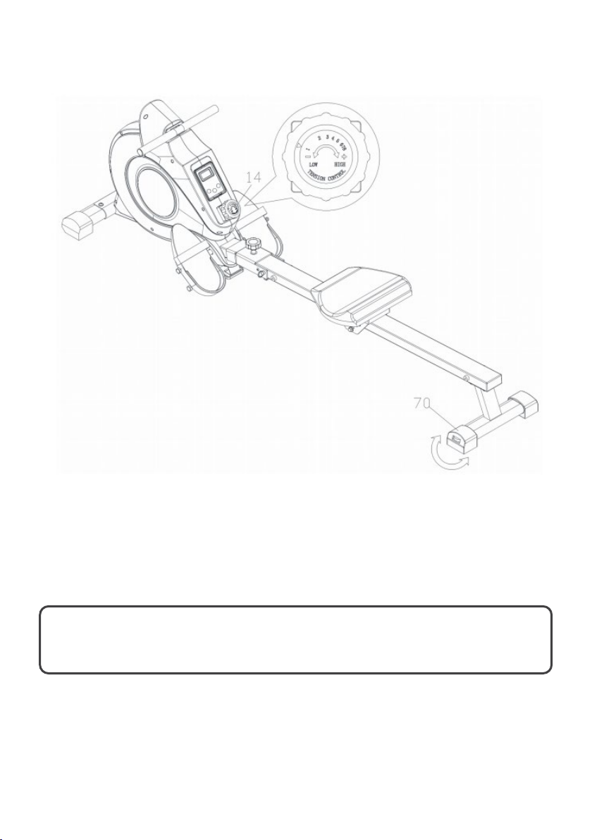
Balance & Resistance
Balance: Adjust the End Caps (No. 70) on the rear stabiliser of the machine if the machine
is unbalanced during use.
Resistance: Rotate the Tension Control Knob (No. 14) clockwise to increase resistance level
from 1 (lowest) to highest (8). Rotate counter-clockwise to decrease resistance.
CAUTION: Moving parts, such as the seat, can cause injury. Keep
hands clear of the sliding rail during use.
16
Page 17
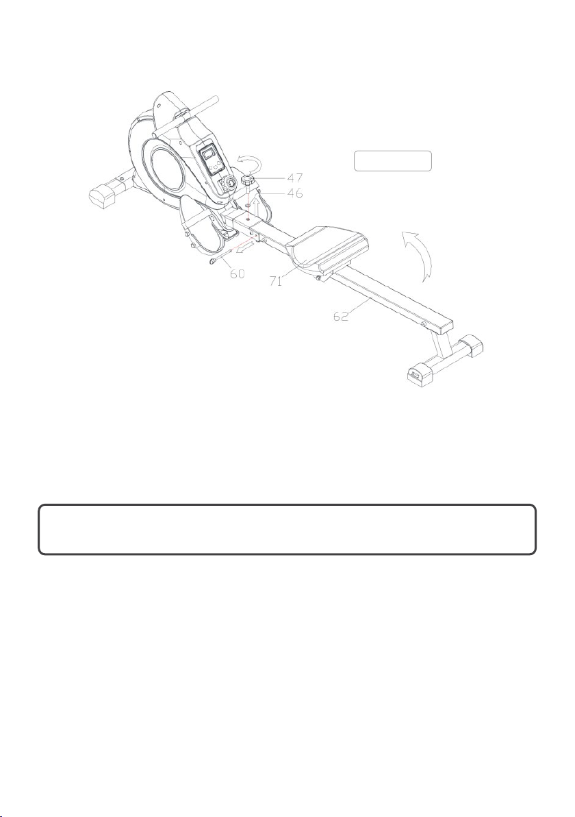
Folding the Machine
Figure 1
When not in use, you can save space by folding the Sliding Rail (No. 62).
Disassemble Knob (No. 47) and Washer (No. 46) and pull out the Pull Pin (No. 60). Fold the
sliding rail to vertical angle (as per Figure 1).
CAUTION: The saddle will glide down when folding the sliding rail.
Reinsert Pull Pin (No. 60) into the hole on the main frame, then tighten Knob (No. 47) and
Washer (No. 46) to Sliding Rail (No. 62) (as per Figure 2).
17
Page 18
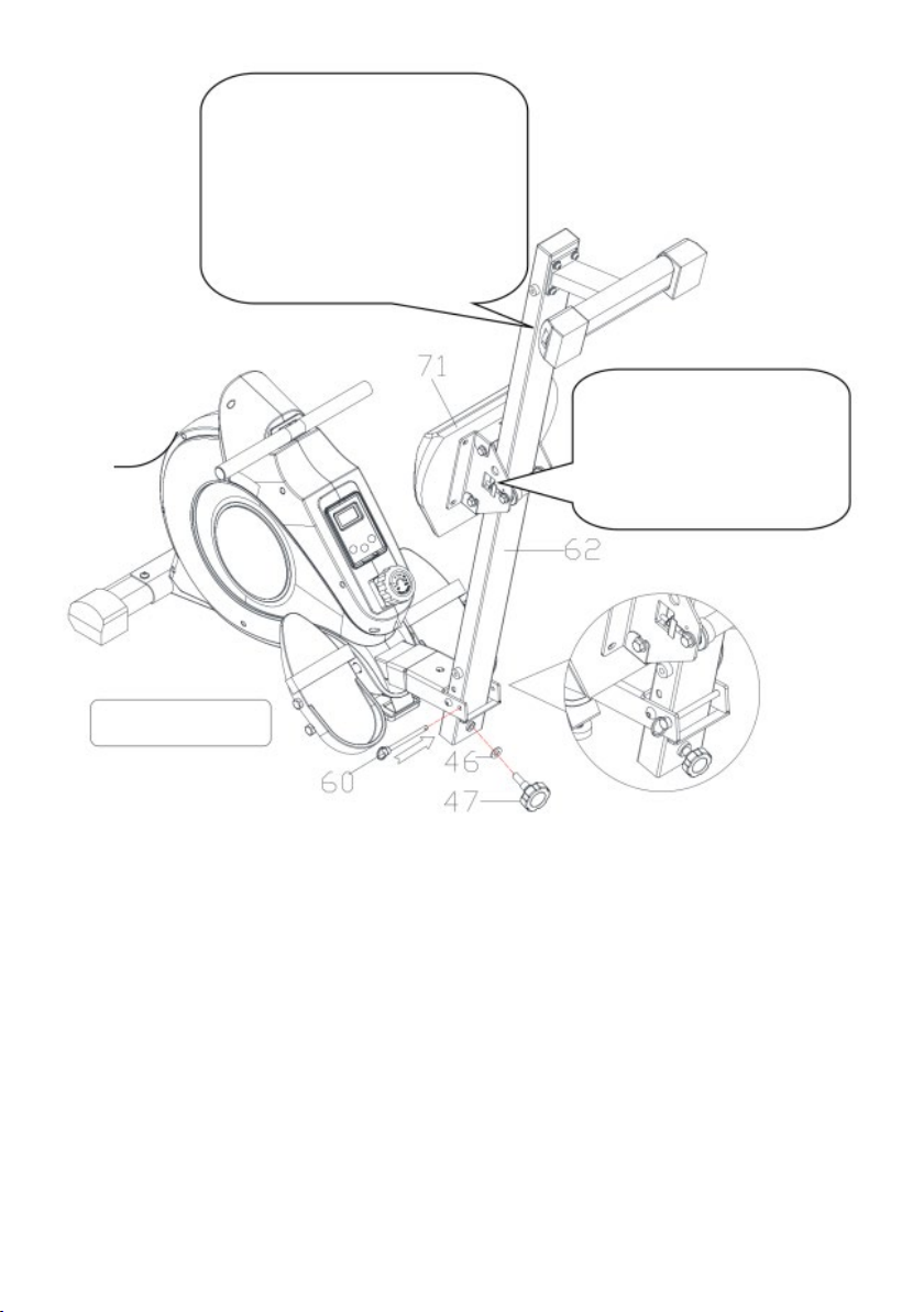
Figure 2
CAUTION: Take care when
vertically folding the Sliding
Rail (No. 62) as your head
may touch the Rear
Support (No. 69).
CAUTION: The saddle
will glide down when
folding the sliding rail!
18
Page 19
Note:
FUNCTION
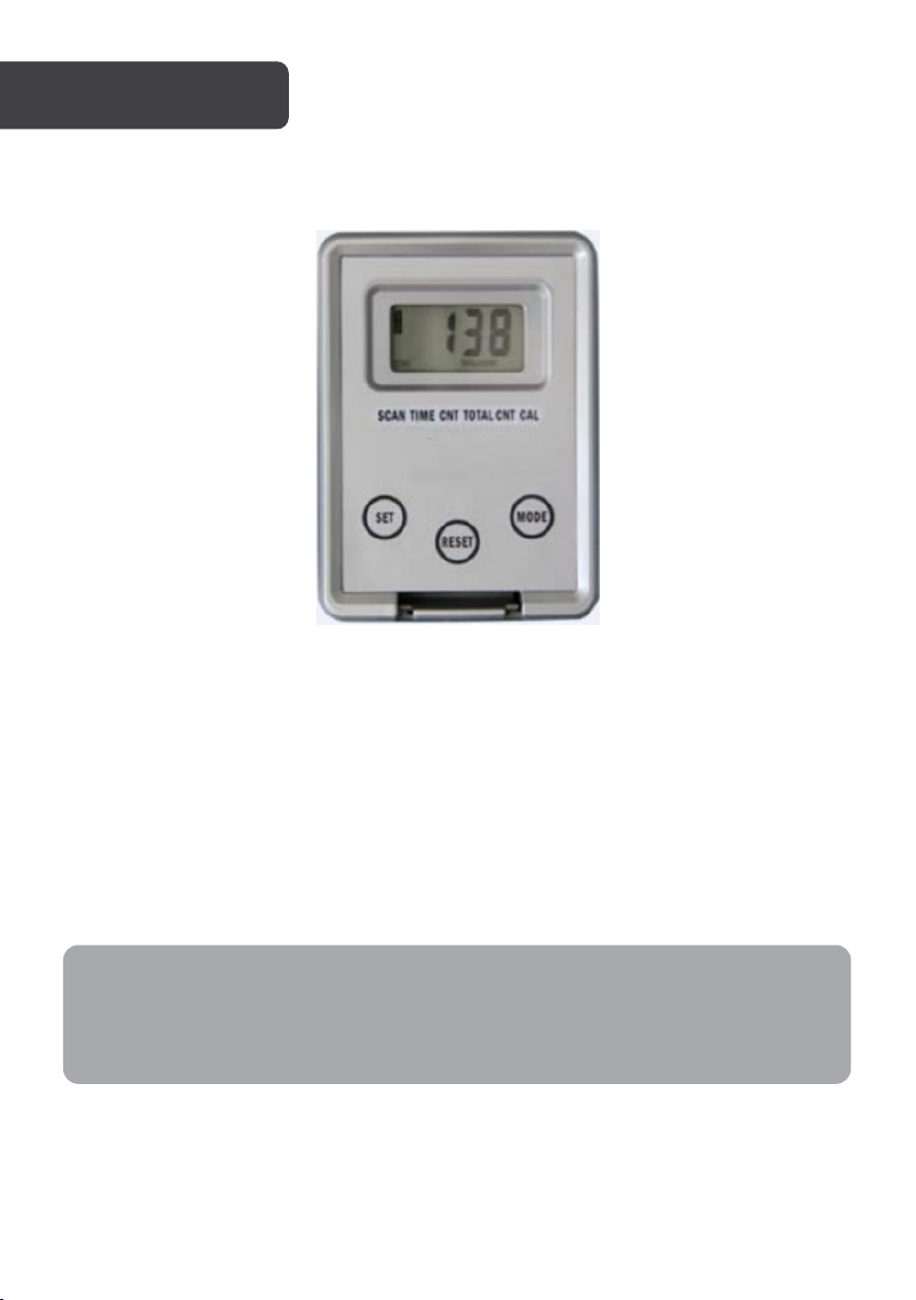
Press MODE to select desired function.
Functions
Battery If the monitor is not displaying properly, replace the battery (2x AAA)
This machine has an auto-shutoff feature. After 4 minutes without a signal, the
monitor will switch off. It will turn back on when an exercise is begun or a key is
pressed.
• Scan
• Time (00:00 - 99:59) Keep track of workout time
• Count (0 - 9999) Keep track of steps taken
• Calories (0 - 999.9 KCAL) Keep track of calories burned
• Total Count (0 - 9999 times/min) Total step count
(Replacements not supplied).
19
Page 20
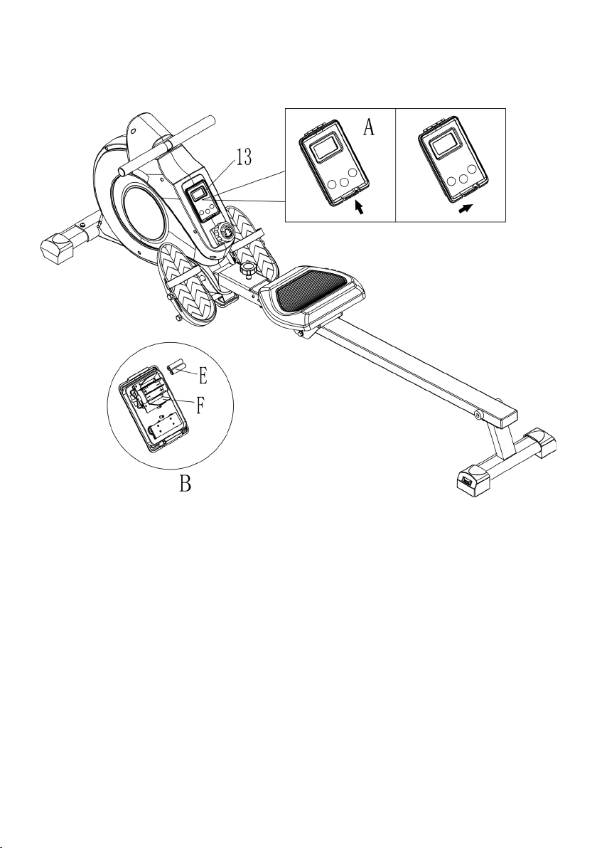
Replacing the computer batterries:
A: Remove the computer
Push the computer (13) buckle forward, and then lift the computer buckle up to remove it.
B: Remove the battery
Open the clasp (F), and then remove the old batteries (E).
20
Page 21
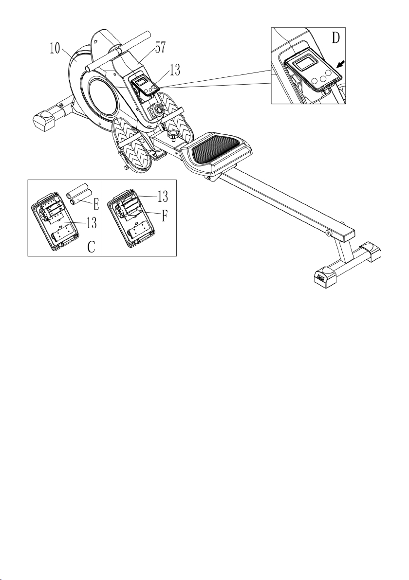
C: Install new batteries
Insert the replacement batteries (E) (x2 AAA batteries), ensuring the polarity markings (+/-)
of the batteries match on the battery compartment, then fasten the clasp (F).
D: Refit the computer
Clip the computer (No. 13) to the left and right chain covers (No. 10/57), and then push the
computer (No. 13) down to clamp it on the left and right chain covers.
21
Page 22
22
Page 23
23
Page 24

Need more information?
We hope that this user guide has given you
the assistance needed for a simple set-up.
For the most up-to-date guide for your product,
as well as any additional assistance you may require,
head online to help.kogan.com
24
 Loading...